

Page 1
STEP 1
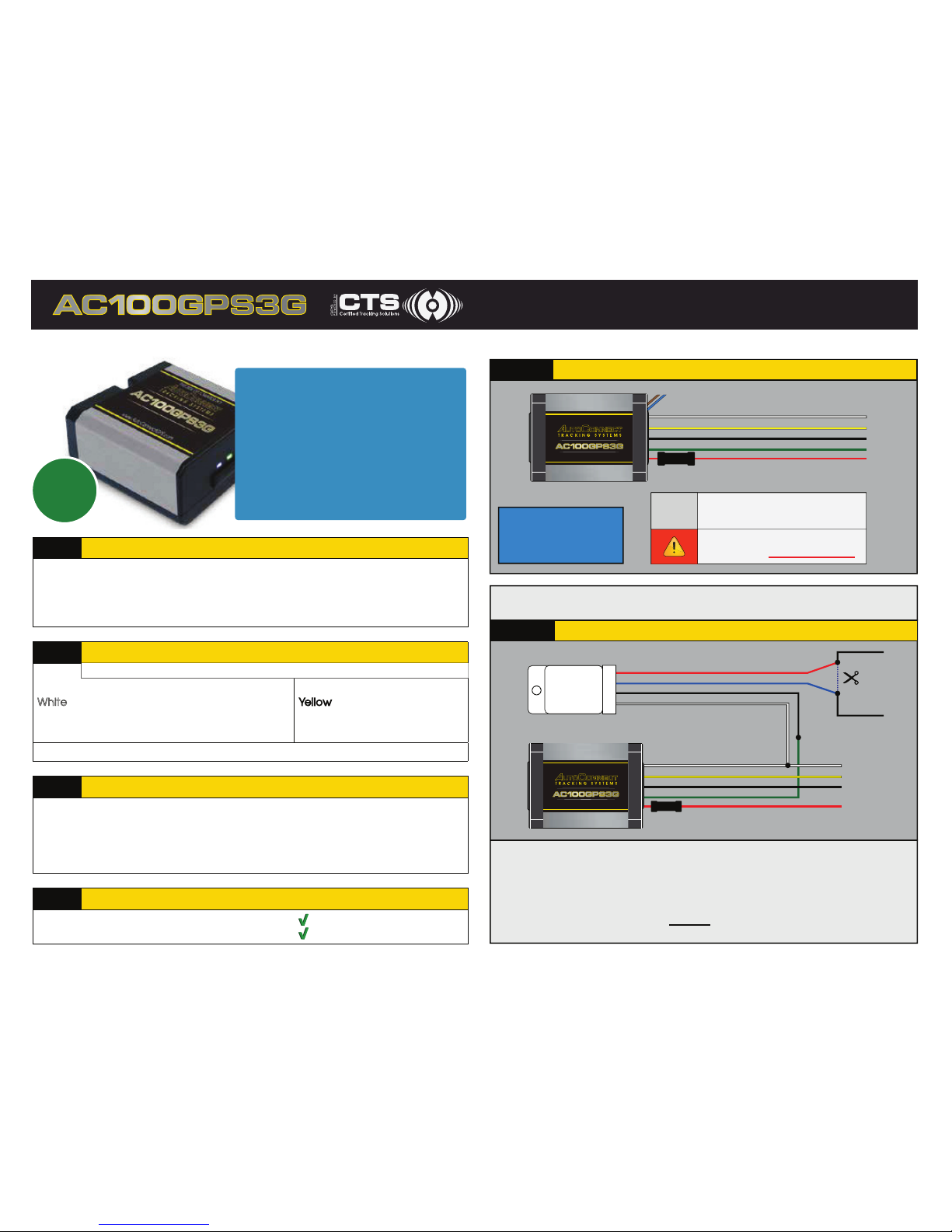
Determine Installation Type and Options
Depending upon the requirements, the AC100GPS3G module can be installed
in two ways.
Type1 – AC100GPS3G GPS Tracking ONLY!
Type2 – AC100GPS3G GPS Tracking with starter kill and/or input
STEP 2
Complete the wire connections according to the selected installation type
Red: 12 Volts (+) Constant
White
: Ignition (+) (MUST be a true ignition source)
Black: Ground
Green: Starter Disable Output (-)
Yellow: Input 1(-) Optional
GROUND MUST BE CONNECTED DIRECTLY TO CHASSIS WITH PAINT REMOVED
STEP 3
Position the AC100GPS3G Module in an Optimal Location
Failure to adhere to these suggestions will result in a weak cellular and/or GPS signal and will
affect the performance of the device.
• Secure in upper portion of dash in a hidden location with correct side pointing
skyward (label will indicate proper orientation). Example: Above instrument cluster.
• Do not cover with metal or position near any source of interference (Vehicle Radio, BCM).
Keep a safe distance of at least 24”.
STEP 4
Confirm LED Status
enilnO / detcennoC gnihsalF :eulB
Green: 1 Flash / Second Valid GPS
Please see the install diagrams for detailed instructions and wiring.
CALL
NO
W
CERTIFIED
TRACKING
SOLUTIONS
1
Type 2 AC100GPS3G with Starter Kill and/or input (optional)
Green - Starter Disable Out (-)
Yellow: Input 1 (-) OPTIONAL
RELAY
Vehicle Start
Interupt Wire*
CUT
Red
White
87A
30
85
86
White - Key Ignition Source (+)
Red (12V+) - Constant
Fuse
Black - GND
Black
Blue
Type 1 AC100GPS3G only
1. Connect Red wire to Constant +12V and fuse.
2. Connect Black wire to Ground.
3. Connect White wire to True Ignition (+).
ATTENTION:
Connecting the device to
24V or 12V to the
Brown or Blue wire WILL VOID THE WARRANTY!
Green - Starter Disable Out (-)
Yellow: Input 1 (-) OPTIONAL
White - Key Ignition Source (+)
Brown/Blue - DATA ONLY
Red (12V+) - Constant
Fuse
Black - GND
1-2- 3!
Numerous installation options exist to interrupt a vehicle’s start sequence.
Please see one possible option below.
Vehicle Start Interrupt Wire
This is a wire that when cut the vehicle is not able to be started by a key.
Due to data bus systems on newer vehicles this wire may not be at the
ignition switch. When cutting a wire be sure to test that the vehicle cannot be
started by key and when reconnected the vehicle starts without fault codes
being displayed by the vehicle. DO NOT CUT THE WIRE THAT WILL SHUT
DOWN THE VEHICLE WHEN RUNNING BY THE KEY.
*
For Live Tech Support:
Call Certified Tracking Solutions at
1.780.391.3800
Toll-Free 1.855.287.4477
8AM - 5PM Monday to Friday MST
12V
ONLY!
QUICK INSTALL GUIDE
REV010517
AutoConnectGPS.com
THIS SIDE UP TOWARDS SKY
AutoConnectGPS.com
THIS SIDE UP TOWARDS SKY
For live Tech Support:
Toll Free 1.855.287.4477
Call Certified Tracking Solutions
8AM to 5PM
1.780.391.3800
Monday to Friday MST
Page 2
Once logged into the AutoConnect dashboard, click on the “Activate Starter
.eriw neerg eht morf tuptuo dnuorg gnihctal a etareneg lliw sihT .dnammoc ”lliK
Please see the Starter Kill wiring diagram for recommended wiring. If successful
you will not be able to start the vehicle. Click on the “Deactivate Starter Kill” to
allow the vehicle to start again.
IMPORTANT: If starter kill is activated while vehicle is running, vehicle
should NOT shut off.
Ensure the vehicle is no longer running.
Once logged into the AutoConnect dashboard, click on the device serial # on
the left side of the screen. The asset info box will open on the bottom left corner
of the screen. Verify that the status of the ignition says “off”.
2 | Test Starter Kill Output (if applicable)
3 | Verify ignition status
STEP 5
Testing
It is HIGHLY recommended that you follow one of the test procedures below to
ensure proper functionality.
Test Procedures
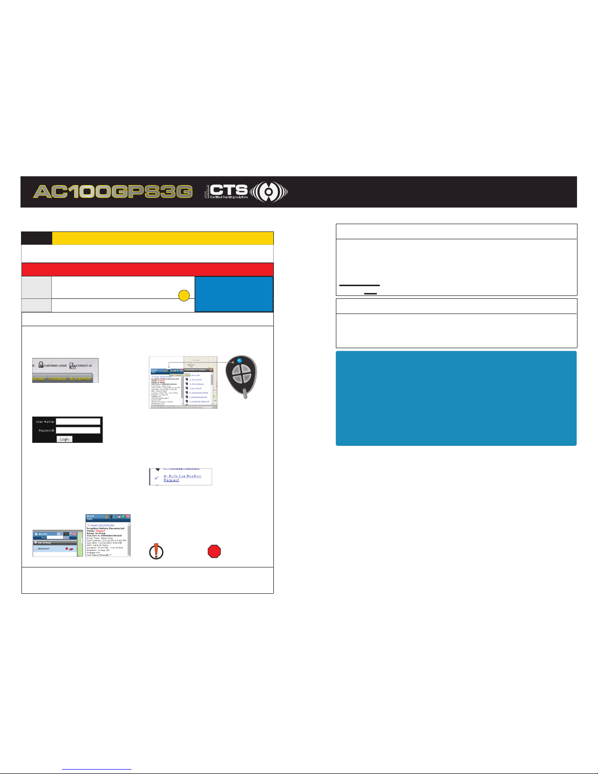
a) Go to
www.AutoconnectGPS.com
and click on “Customer Login”
d) Click on device serial #
on the left side of the screen.
The asset info box will open
on the bottom left corner of
the screen.
The successful completion of this
section will enable you to see the
b) Enter the User Name and
password for your account
c) Click “Login”.
e) Click on the “Asset Commands &
Controls” icon located at the top of
the Asset Info box
f ) Click on command labeled
“A – Bulls Eye Position Request”.
A successful completion of this
command will result in a checkmark
being displayed and the current
time will update in the “Last Comms”
section of the asset info box.
g) The vehicle icon on the map
should now have a red “dot” below
it. If it has an exclamation mark
(“!”), it means that the device has
“invalid” GPS. In this case you will
need to move the vehicle outside
and issue the Bulls Eye request again.
Invalid GPS Valid GPS
If you are still unable to see an updated location you can force a GPS
position through by disconnecting the modem from the power harness for 3
minutes and then reconnecting again.
or
For Live Tech Support:
Call Certified Tracking Solutions at
1.780.391.3800
Toll-Free 1.855.287.4477
8AM - 5PM Monday to Friday MST
1 | Confirm Vehicle Connectivity and GPS Location
Call CTS
to Test
Self Test
a) Have the ESN# ready and call CTS to test the
ignition, GPS and star ter kill (if applicable)
b) Login to view and test the device
QUICK INSTALL GUIDE
For live Tech Support:
Toll Free 1.855.287.4477
Call Certified Tracking Solutions at 1.780.391.3800
8AM to 5PM Monday to Friday MST
current location of the device on
the website.
REV010517
 Loading...