

Page 1

AutoCAD 2013
AutoLISP Developer's Guide
January 2012
Page 2

©
2012 Autodesk, Inc. All Rights Reserved. Except as otherwise permitted by Autodesk, Inc., this publication, or parts thereof, may not
be reproduced in any form, by any method, for any purpose.
Certain materials included in this publication are reprinted with the permission of the copyright holder.
Trademarks
The following are registered trademarks or trademarks of Autodesk, Inc., and/or its subsidiaries and/or affiliates in the USA and other countries:
123D, 3ds Max, Algor, Alias, Alias (swirl design/logo), AliasStudio, ATC, AUGI, AutoCAD, AutoCAD Learning Assistance, AutoCAD LT, AutoCAD
Simulator, AutoCAD SQL Extension, AutoCAD SQL Interface, Autodesk, Autodesk Homestyler, Autodesk Intent, Autodesk Inventor, Autodesk
MapGuide, Autodesk Streamline, AutoLISP, AutoSketch, AutoSnap, AutoTrack, Backburner, Backdraft, Beast, Beast (design/logo) Built with
ObjectARX (design/logo), Burn, Buzzsaw, CAiCE, CFdesign, Civil 3D, Cleaner, Cleaner Central, ClearScale, Colour Warper, Combustion,
Communication Specification, Constructware, Content Explorer, Creative Bridge, Dancing Baby (image), DesignCenter, Design Doctor, Designer's
Toolkit, DesignKids, DesignProf, DesignServer, DesignStudio, Design Web Format, Discreet, DWF, DWG, DWG (design/logo), DWG Extreme,
DWG TrueConvert, DWG TrueView, DWFX, DXF, Ecotect, Evolver, Exposure, Extending the Design Team, Face Robot, FBX, Fempro, Fire, Flame,
Flare, Flint, FMDesktop, Freewheel, GDX Driver, Green Building Studio, Heads-up Design, Heidi, Homestyler, HumanIK, IDEA Server, i-drop,
Illuminate Labs AB (design/logo), ImageModeler, iMOUT, Incinerator, Inferno, Instructables, Instructables (stylized robot design/logo),Inventor,
Inventor LT, Kynapse, Kynogon, LandXplorer, LiquidLight, LiquidLight (design/logo), Lustre, MatchMover, Maya, Mechanical Desktop, Moldflow,
Moldflow Plastics Advisers, Moldflow Plastics Insight, Moldflow Plastics Xpert, Moondust, MotionBuilder, Movimento, MPA, MPA (design/logo),
MPI, MPI (design/logo), MPX, MPX (design/logo), Mudbox, Multi-Master Editing, Navisworks, ObjectARX, ObjectDBX, Opticore, Pipeplus, Pixlr,
Pixlr-o-matic, PolarSnap, PortfolioWall, Powered with Autodesk Technology, Productstream, ProMaterials, RasterDWG, RealDWG, Real-time
Roto, Recognize, Render Queue, Retimer, Reveal, Revit, RiverCAD, Robot, Scaleform, Scaleform GFx, Showcase, Show Me, ShowMotion,
SketchBook, Smoke, Softimage, Softimage|XSI (design/logo), Sparks, SteeringWheels, Stitcher, Stone, StormNET, Tinkerbox, ToolClip, Topobase,
Toxik, TrustedDWG, U-Vis, ViewCube, Visual, Visual LISP, Voice Reality, Volo, Vtour, WaterNetworks, Wire, Wiretap, WiretapCentral, XSI.
All other brand names, product names or trademarks belong to their respective holders.
Disclaimer
THIS PUBLICATION AND THE INFORMATION CONTAINED HEREIN IS MADE AVAILABLE BY AUTODESK, INC. "AS IS." AUTODESK, INC. DISCLAIMS
ALL WARRANTIES, EITHER EXPRESS OR IMPLIED, INCLUDING BUT NOT LIMITED TO ANY IMPLIED WARRANTIES OF MERCHANTABILITY OR
FITNESS FOR A PARTICULAR PURPOSE REGARDING THESE MATERIALS.
Page 3

Contents
Chapter 1 Introduction . . . . . . . . . . . . . . . . . . . . . . . . . . . . 1
Introduction . . . . . . . . . . . . . . . . . . . . . . . . . . . . . . . . 1
AutoLISP . . . . . . . . . . . . . . . . . . . . . . . . . . . . . . . 1
About Related AutoLISP Documents . . . . . . . . . . . . . . . . . 2
Chapter 2 Using the AutoLISP Language . . . . . . . . . . . . . . . . . . . 3
AutoLISP Basics . . . . . . . . . . . . . . . . . . . . . . . . . . . . . . . 3
AutoLISP Expressions . . . . . . . . . . . . . . . . . . . . . . . . . 3
AutoLISP Function Syntax . . . . . . . . . . . . . . . . . . . 5
AutoLISP Data Types . . . . . . . . . . . . . . . . . . . . . . . . . 6
Integers . . . . . . . . . . . . . . . . . . . . . . . . . . . . . 6
Reals . . . . . . . . . . . . . . . . . . . . . . . . . . . . . . 7
Strings . . . . . . . . . . . . . . . . . . . . . . . . . . . . . 8
Lists . . . . . . . . . . . . . . . . . . . . . . . . . . . . . . . 8
Selection Sets . . . . . . . . . . . . . . . . . . . . . . . . . . 8
Entity Names . . . . . . . . . . . . . . . . . . . . . . . . . . 8
File Descriptors . . . . . . . . . . . . . . . . . . . . . . . . . 9
Symbols and Variables . . . . . . . . . . . . . . . . . . . . 10
AutoLISP Program Files . . . . . . . . . . . . . . . . . . . . . . . 11
Formatting AutoLISP Code . . . . . . . . . . . . . . . . . . 11
Comments in AutoLISP Program Files . . . . . . . . . . . . 11
AutoLISP Variables . . . . . . . . . . . . . . . . . . . . . . . . . 12
Displaying the Value of a Variable . . . . . . . . . . . . . . 13
iii
Page 4

Nil Variables . . . . . . . . . . . . . . . . . . . . . . . . . . 13
Predefined Variables . . . . . . . . . . . . . . . . . . . . . . 13
Number Handling . . . . . . . . . . . . . . . . . . . . . . . . . . 14
String Handling . . . . . . . . . . . . . . . . . . . . . . . . . . . 14
Basic Output Functions . . . . . . . . . . . . . . . . . . . . . . . 16
Displaying Messages . . . . . . . . . . . . . . . . . . . . . 17
Control Characters in Strings . . . . . . . . . . . . . . . . . 18
Wild-Card Matching . . . . . . . . . . . . . . . . . . . . . 20
Equality and Conditional . . . . . . . . . . . . . . . . . . . . . . 21
List Handling . . . . . . . . . . . . . . . . . . . . . . . . . . . . 21
Point Lists . . . . . . . . . . . . . . . . . . . . . . . . . . . 23
Dotted Pairs . . . . . . . . . . . . . . . . . . . . . . . . . . 26
Symbol and Function Handling . . . . . . . . . . . . . . . . . . 28
Using defun to Define a Function . . . . . . . . . . . . . . 28
C:XXX Functions . . . . . . . . . . . . . . . . . . . . . . . 30
Local Variables in Functions . . . . . . . . . . . . . . . . . 34
Functions with Arguments . . . . . . . . . . . . . . . . . . 36
Error Handling in AutoLISP . . . . . . . . . . . . . . . . . . . . . 38
Using the *error* Function . . . . . . . . . . . . . . . . . . 39
Catching Errors and Continuing Program Execution . . . . 41
Using AutoLISP to Communicate with AutoCAD . . . . . . . . . . . . 42
Accessing Commands and Services . . . . . . . . . . . . . . . . . 42
Command Submission . . . . . . . . . . . . . . . . . . . . 43
System and Environment Variables . . . . . . . . . . . . . . 47
Configuration Control . . . . . . . . . . . . . . . . . . . . 47
Display Control . . . . . . . . . . . . . . . . . . . . . . . . . . . 47
Control of Graphics and Text Windows . . . . . . . . . . . 48
Control of Low-Level Graphics . . . . . . . . . . . . . . . . 48
Getting User Input . . . . . . . . . . . . . . . . . . . . . . . . . 49
The getxxx Functions . . . . . . . . . . . . . . . . . . . . . 49
Control of User-Input Function Conditions . . . . . . . . . 52
Geometric Utilities . . . . . . . . . . . . . . . . . . . . . . . . . 55
Object Snap . . . . . . . . . . . . . . . . . . . . . . . . . . 56
Text Extents . . . . . . . . . . . . . . . . . . . . . . . . . . 56
Conversions . . . . . . . . . . . . . . . . . . . . . . . . . . . . . 61
String Conversions . . . . . . . . . . . . . . . . . . . . . . 61
Angular Conversion . . . . . . . . . . . . . . . . . . . . . . 64
ASCII Code Conversion . . . . . . . . . . . . . . . . . . . . 65
Unit Conversion . . . . . . . . . . . . . . . . . . . . . . . 67
Coordinate System Transformations . . . . . . . . . . . . . 70
File Handling . . . . . . . . . . . . . . . . . . . . . . . . . . . . 72
File Search . . . . . . . . . . . . . . . . . . . . . . . . . . . 73
Device Access and Control . . . . . . . . . . . . . . . . . . . . . 74
Accessing User Input . . . . . . . . . . . . . . . . . . . . . 74
Using AutoLISP to Manipulate AutoCAD Objects . . . . . . . . . . . . 74
Selection Set Handling . . . . . . . . . . . . . . . . . . . . . . . 75
iv | Contents
Page 5

Selection Set Filter Lists . . . . . . . . . . . . . . . . . . . . 77
Passing Selection Sets between AutoLISP and ObjectARX
Applications . . . . . . . . . . . . . . . . . . . . . . . . . 85
Object Handling . . . . . . . . . . . . . . . . . . . . . . . . . . . 86
Entity Name Functions . . . . . . . . . . . . . . . . . . . . 86
Entity Data Functions . . . . . . . . . . . . . . . . . . . . . 92
Entity Data Functions and the Graphics Screen . . . . . . . 102
Old-Style Polylines and Lightweight Polylines . . . . . . . 103
Non-Graphic Object Handling . . . . . . . . . . . . . . . 104
Extended Data - xdata . . . . . . . . . . . . . . . . . . . . . . . 106
Organization of Extended Data . . . . . . . . . . . . . . . 107
Registration of an Application . . . . . . . . . . . . . . . . 109
Retrieval of Extended Data . . . . . . . . . . . . . . . . . 110
Attachment of Extended Data to an Entity . . . . . . . . . 111
Management of Extended Data Memory Use . . . . . . . . 112
Handles in Extended Data . . . . . . . . . . . . . . . . . . 112
Xrecord Objects . . . . . . . . . . . . . . . . . . . . . . . . . . 113
Symbol Table and Dictionary Access . . . . . . . . . . . . . . . 114
Symbol Tables . . . . . . . . . . . . . . . . . . . . . . . . 114
Dictionary Entries . . . . . . . . . . . . . . . . . . . . . . 116
Chapter 3 Appendixes . . . . . . . . . . . . . . . . . . . . . . . . . . . . 119
AutoLISP Function Synopsis . . . . . . . . . . . . . . . . . . . . . . . 119
Category Summary . . . . . . . . . . . . . . . . . . . . . . . . . 119
Basic Functions . . . . . . . . . . . . . . . . . . . . . . . . . . . 121
Application-Handling Functions . . . . . . . . . . . . . . 121
Arithmetic Functions . . . . . . . . . . . . . . . . . . . . 122
Equality and Conditional Functions . . . . . . . . . . . . 125
Error-Handling Functions . . . . . . . . . . . . . . . . . . 126
Function-Handling Functions . . . . . . . . . . . . . . . . 127
List Manipulation Functions . . . . . . . . . . . . . . . . 128
String-Handling Functions . . . . . . . . . . . . . . . . . 131
Symbol-Handling Functions . . . . . . . . . . . . . . . . . 133
Utility Functions . . . . . . . . . . . . . . . . . . . . . . . . . . 134
Conversion Functions . . . . . . . . . . . . . . . . . . . . 134
Device Access Functions . . . . . . . . . . . . . . . . . . . 135
Display Control Functions . . . . . . . . . . . . . . . . . . 136
File-Handling Functions . . . . . . . . . . . . . . . . . . . 137
Geometric Functions . . . . . . . . . . . . . . . . . . . . 139
Query and Command Functions . . . . . . . . . . . . . . 139
User Input Functions . . . . . . . . . . . . . . . . . . . . 141
Selection Set, Object, and Symbol Table Functions . . . . . . . . 142
Extended Data-Handling Functions . . . . . . . . . . . . . 143
Object-Handling Functions . . . . . . . . . . . . . . . . . 143
Selection Set Manipulation Functions . . . . . . . . . . . . 145
Symbol Table and Dictionary-Handling Functions . . . . . 146
Contents | v
Page 6

Memory Management Functions . . . . . . . . . . . . . . . . . 147
VLX Namespace Functions . . . . . . . . . . . . . . . . . . . . 147
Namespace Communication Functions . . . . . . . . . . . . . . 148
Property List (Plist) Functions . . . . . . . . . . . . . . . . . . . 149
AutoLISP Error Codes . . . . . . . . . . . . . . . . . . . . . . . . . . 149
Error Codes . . . . . . . . . . . . . . . . . . . . . . . . . . . . . 149
Index . . . . . . . . . . . . . . . . . . . . . . . . . . . . . . . 157
vi | Contents
Page 7

Introduction
Introduction
For years, AutoLISP® has set the standard for customizing AutoCAD® on
Windows®. AutoCAD also supports AutoLISP, but does not support many of
the Visual LISP functions or the Microsoft ActiveX® Automation interface.
AutoCAD does not have an integrated development environment like AutoCAD
on Windows does, so the creation and editing of LSP files must be done with
text editor such as TextEdit.
AutoLISP
AutoLISP is a programming language designed for extending and customizing
the functionality of AutoCAD. It is based on the LISP programming language,
whose origins date back to the late 1950s. LISP was originally designed for use
in Artificial Intelligence (AI) applications, and is still the basis for many AI
applications.
1
AutoLISP was introduced as an application programming interface (API) in
AutoCAD Release 2.1, in the mid-1980s. LISP was chosen as the initial AutoCAD
API because it was uniquely suited for the unstructured design process of
AutoCAD projects, which involved repeatedly trying different solutions to design
problems.
Developing AutoLISP programs for AutoCAD is done by writing code in a text
editor, then loading the code into AutoCAD and running it. Debugging your
program is handled by adding statements to print the contents of variables at
strategic points in your program. You must figure out where in your program
to do this, and what variables you need to look at. If you discover you do not
have enough information to determine the error, you must go back and change
1
Page 8

the code by adding more debugging points. And finally, when you get the
program to work correctly, you need to either comment out or remove the
debugging code you added.
About Related AutoLISP Documents
In addition to the AutoLISP Reference, several other AutoCAD publications may
be required by users building applications with AutoLISP:
■ AutoCADCustomization Guide contains basic information on creating
customized AutoCAD applications. For example, it includes information
on creating customized user interface elements, linetypes, and hatch
patterns. The Customization Guide is available through the AutoCAD and
Help menu on the Mac OS menu bar.
■ The DXF Reference describes drawing interchange format (DXF
DXF group codes that identify attributes of AutoCAD objects.
The DXF Reference is not included when you install AutoCAD. To obtain
the manual, download the DXF Reference from www.autodesk.com.
■ The ObjectARX Reference contains information on using ObjectARX
develop customized AutoCAD applications. AutoCAD reactor functionality
is implemented through ObjectARX. If you develop AutoLISP applications
that implement reactor functions, you may want to refer to this manual.
The ObjectARX Reference is not included when you install AutoCAD. To
obtain the manual, download the ObjectARX SDK (Software Development
Kit) from www.autodesk.com.
TM
) and the
®
to
2 | Chapter 1 Introduction
Page 9

Using the AutoLISP Language
AutoLISP Basics
You can use number, string, and list-handling functions to customize AutoCAD.
This chapter introduces the basic concepts of the AutoLISP® programming
language. It describes the core components and data types used in AutoLISP,
and presents examples of simple number-, string-, output-, and list-handling
functions.
AutoLISP code does not need to be compiled, so you can enter the code at a
Command line and immediately see the results.
2
AutoLISP Expressions
An AutoLISP program consists of a series of expressions. AutoLISP expressions
have the following form:
(function
arguments
)
Each expression begins with an open (left) parenthesis and consists of a function
name and optional arguments to that function. Each argument can also be an
expression. The expression ends with a right parenthesis. Every expression
returns a value that can be used by a surrounding expression. The value of the
last interpreted expression is returned to the calling expression.
For example, the following code example involves three functions:
3
Page 10

(fun1 (fun2
arguments)(fun3
arguments)
)
If you enter this code at the AutoCAD Command prompt, the AutoCAD
AutoLISP interpreter processes the code. The first function, fun1, has two
arguments, and the other functions, fun2 and fun3, each have one argument.
The functions fun2 and fun3 are surrounded by function fun1, so their return
values are passed to fun1 as arguments. Function fun1 evaluates the two
arguments and returns the value to the window from which you entered the
code.
The following example shows the use of the * (multiplication) function, which
accepts one or more numbers as arguments:
(* 2 27)
54
Because this code example has no surrounding expression, AutoLISP returns
the result to the window from which you entered the code.
Expressions nested within other expressions return their result to the
surrounding expression. The following example uses the result from the +
(addition) function as one of the arguments for the * (multiplication) function.
(* 2 (+ 5 10))
30
If you enter the incorrect number of close (right) parentheses, AutoLISP displays
the following prompt:
(_>
The number of open parentheses in this prompt indicates how many levels
of open parentheses remain unclosed. If this prompt appears, you must enter
the required number of close parentheses for the expression to be evaluated.
(* 2 (+ 5 10
((_>
) )
30
4 | Chapter 2 Using the AutoLISP Language
Page 11

A common mistake is to omit the closing quotation mark (") in a text string,
in which case the close parentheses are interpreted as part of the string and
have no effect in resolving the open parentheses. To correct this condition,
press Shift+Esc to cancel the function, then re-enter it correctly.
AutoLISP Function Syntax
In this guide, the following conventions describe the syntax for AutoLISP
functions:
In this example, the foo function has one required argument, string, and one
optional argument, number. Additional number arguments can be provided.
Frequently, the name of the argument indicates the expected data type. The
examples in the following table show both valid and invalid calls to the foo
function.
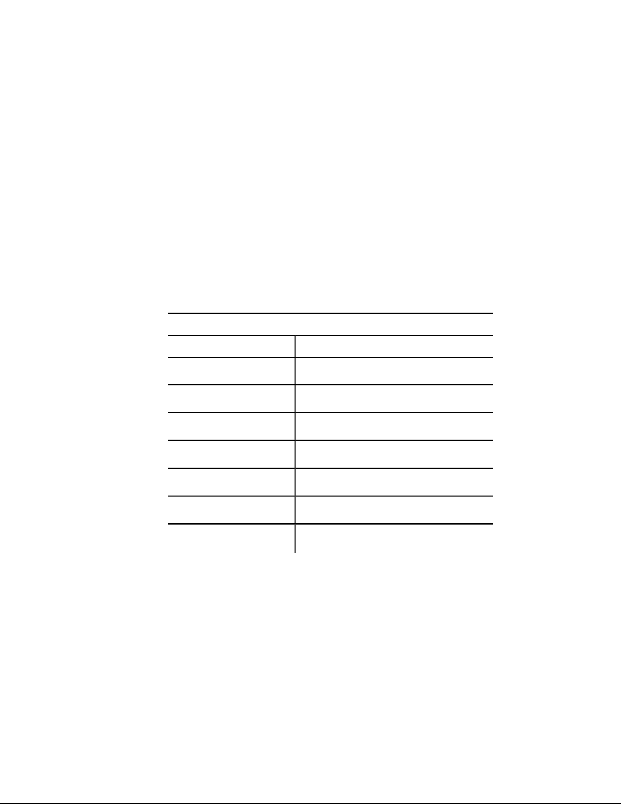
Valid and invalid function call examples
Invalid callsValid calls
(foo 44 13)(foo "catch")
(foo "fi" "foe" 44 13)(foo "catch" 22)
(foo)(foo "catch" 22 31)
AutoLISP Basics | 5
Page 12

AutoLISP Data Types
AutoLISP expressions are processed according to the order and data type of
the code within the parentheses. Before you can fully utilize AutoLISP, you
must understand the differences among the data types and how to use them.
Integers
Integers are whole numbers that do not contain a decimal point. AutoLISP
integers are 32-bit signed numbers with values ranging from +2,147,483,647
to -2,147,483,648. (Note, however, that the getint function only accepts 16-bit
numbers ranging from +32767 to -32678.) When you explicitly use an integer
in an AutoLISP expression, that value is known as a constant. Numbers such
as 2, -56, and 1,200,196 are valid AutoLISP integers.
If you enter a number that is greater than the maximum integer allowed
(resulting in integer overflow), AutoLISP converts the integer to a real number.
However, if you perform an arithmetic operation on two valid integers, and
the result is greater than the maximum allowable integer, the resulting number
will be invalid. The following examples illustrate how AutoLISP handles integer
overflow.
The largest positive integer value retains its specified value:
2147483647
2147483647
If you enter an integer that is greater than the largest allowable value, AutoLISP
returns the value as a real:
2147483648
2.14748e+009
An arithmetic operation involving two valid integers, but resulting in integer
overflow, produces an invalid result:
(+ 2147483646 3)
-2147483647
6 | Chapter 2 Using the AutoLISP Language
Page 13

In this example the result is clearly invalid, as the addition of two positive
numbers results in a negative number. But note how the following operation
produces a valid result:
(+ 2147483648 2)
2.14748e+009
In this instance, AutoLISP converts 2147483648 to a valid real before adding
2 to the number. The result is a valid real.
The largest negative integer value retains its specified value:
-2147483647
-2147483647
If you enter a negative integer larger than the greatest allowable negative
value, AutoLISP returns the value as a real:
-2147483648
-2.14748e+009
The following operation concludes successfully, because AutoLISP first converts
the overflow negative integer to a valid real:
(- -2147483648 1)
-2.14748e+009
Reals
A real is a number containing a decimal point. Numbers between -1 and 1
must contain a leading zero. Real numbers are stored in double-precision
floating-point format, providing at least 14 significant digits of precision.
Reals can be expressed in scientific notation, which has an optional e or E
followed by the exponent of the number (for example, 0.0000041 is the same
as 4.1e-6). Numbers such as 3.1, 0.23, -56.123, and 21,000,000.0 are valid
AutoLISP reals.
AutoLISP Basics | 7
Page 14

Strings
A string is a group of characters surrounded by quotation marks. Within quoted
strings the backslash (\) character allows control characters (or escape codes)
to be included. When you explicitly use a quoted string in an AutoLISP
expression, that value is known as a literal string or a string constant.
Examples of valid strings are “string 1” and “\nEnter first point:”.
Lists
An AutoLISP list is a group of related values separated by spaces and enclosed
in parentheses. Lists provide an efficient method of storing numerous related
values. AutoCAD expresses 3D points as a list of three real numbers.
Examples of lists are (1.0 1.0 0.0), (“this” “that” “the other”), and (1 “ONE”).
Selection Sets
Selection sets are groups of one or more objects (entities). You can interactively
add objects to, or remove objects from, selection sets with AutoLISP routines.
The following example uses the ssget function to return a selection set
containing all the objects in a drawing.
(ssget "X")
<Selection set: 1>
Entity Names
An entity name is a numeric label assigned to objects in a drawing. It is actually
a pointer into a file maintained by AutoCAD, and can be used to find the
object's database record and its vectors (if they are displayed). This label can
be referenced by AutoLISP functions to allow selection of objects for processing
in various ways. Internally, AutoCAD refers to objects as entities.
The following example uses the entlast function to get the name of the last
object entered into the drawing.
8 | Chapter 2 Using the AutoLISP Language
Page 15

(entlast)
<Entity name: 27f0540>
Entity names assigned to objects in a drawing are only in effect during the
current editing session. The next time you open the drawing, AutoCAD assigns
new entity names to the objects. You can use an object's handle to refer to it
from one editing session to another; see Entity Handles and Their Uses (page
87) for information on using handles.
File Descriptors
A file descriptor is a pointer to a file opened by the AutoLISP open function.
The open function returns this pointer as an alphanumeric label. You supply
the file descriptor as an argument to other AutoLISP functions that read or
write to the file.
The following example opens the myinfo.dat file for reading. The open function
returns the file descriptor:
(setq file1 (open "/myinfo.dat" "r") )
#<file "/myinfo.dat">
In this example, the file descriptor is stored in the file1variable.
Files remain open until you explicitly close them in your AutoLISP program.
The close function closes a file. The following code closes the file whose file
descriptor is stored in the file1 variable:
(close file1)
nil
AutoLISP Basics | 9
Page 16

Symbols and Variables
AutoLISP uses symbols to refer to data. Symbol names are not case sensitive
and may consist of any sequence of alphanumeric and notation characters,
except the following:
Characters restricted from symbol names
(
)
.
'
"
;
(Open Parenthesis)
(Close Parenthesis)
(Period)
(Apostrophe)
(Quote Symbol)
(Semicolon)
A symbol name cannot consist only of numeric characters.
Technically, AutoLISP applications consist of either symbols or constant values,
such as strings, reals, and integers. For the sake of clarity, this guide uses the
term symbol to refer to a symbol name that stores static data, such as built-in
and user-defined functions. The term variable is used to refer to a symbol name
that stores program data. The following example uses the setq function to
assign the string value "this is a string" to the str1 variable:
(setq str1 "this is a string")
"this is a string"
Help yourself and others who need to read your code. Choose meaningful
names for your program symbols and variables.
10 | Chapter 2 Using the AutoLISP Language
Page 17

AutoLISP Program Files
Although you can enter AutoLISP code at the AutoCAD Command prompt,
testing and debugging a series of instructions are considerably easier when
you save AutoLISP code in a file rather than re-entering it each time you make
a refinement. AutoLISP source code is usually stored in ASCII text files with
an .lsp extension. However, you can load AutoLISP code from any ASCII text
file.
Formatting AutoLISP Code
The extensive use of parentheses in AutoLISP code can make it difficult to
read. The traditional technique for combatting this confusion is indentation.
The more deeply nested a line of code is, the farther to the right you position
the line.
Spaces in AutoLISP Code
In AutoLISP, multiple spaces between variable names, constants, and function
names are equivalent to a single space. The end of a line is also treated as a
single space.
The following two expressions produce the same result:
(setq test1 123 test2 456)
(setq
test1 123
test2 456
)
Comments in AutoLISP Program Files
It is good practice to include comments in AutoLISP program files. Comments
are useful to both the programmer and future users who may need to revise
a program to suit their needs. Use comments to do the following:
■ Give a title, authorship, and creation date
■ Provide instructions on using a routine
■ Make explanatory notes throughout the body of a routine
AutoLISP Basics | 11
Page 18

■ Make notes to yourself during debugging
Comments begin with one or more semicolons (;) and continue through the
end of the line.
; This entire line is a comment
(setq area (* pi r r)) ; Compute area of circle
Any text within ;| ... |; is ignored. Therefore, comments can be included
within a line of code or extend for multiple lines. This type of comment is
known as an in-line comment.
(setq tmode ;|some note here|; (getvar "tilemode"))
The following example shows a comment that continues for multiple lines:
(setvar "orthomode" 1) ;|comment starts here
and continues to this line,
but ends way down here|; (princ "\nORTHOMODE set On.")
It is recommended that you use comments liberally when writing AutoLISP
programs.
AutoLISP Variables
An AutoLISP variable assumes the data type of the value assigned to it. Until
they are assigned new values, variables retain their original values. You use
the AutoLISP setq function to assign values to variables.
(setq
variable_name1 value1 [variable_name2 value2 ...]
)
The setq function assigns the specified value to the variable name given. It
returns the value as its function result.
(setq val 3 abc 3.875)
3.875
(setq layr "EXTERIOR-WALLS")
"EXTERIOR-WALLS"
12 | Chapter 2 Using the AutoLISP Language
Page 19

Displaying the Value of a Variable
To display the value of a variable from the AutoCAD Command prompt, you
must precede the variable name with an exclamation point (!). For example:
!abc
3.875
Nil Variables
An AutoLISP variable that has not been assigned a value is said to be nil. This
is different from blank, which is considered a character string, and different
from 0, which is a number. So, in addition to checking a variable for its current
value, you can test to determine if the variable has been assigned a value.
Each variable consumes a small amount of memory, so it is good programming
practice to reuse variable names or set variables to nil when their values are
no longer needed. Setting a variable to nil releases the memory used to store
that variable's value. If you no longer need the val variable, you can release
its value from memory with the following expression:
(setq val nil)
nil
Another efficient programming practice is to use local variables whenever
possible. See Local Variables in Functions (page 34) on this topic.
Predefined Variables
The following predefined variables are commonly used in AutoLISP
applications:
PAUSE Defined as a string consisting of a double backslash (\\) character. This
variable is used with the command function to pause for user input.
PI Defined as the constant p (pi). It evaluates to approximately 3.14159.
T Defined as the constant T. This is used as a non-nil value.
AutoLISP Basics | 13
Page 20

NOTE You can change the value of these variables with the setq function. However,
other applications might rely on their values being consistent; therefore, it is
recommended that you do not modify these variables.
Number Handling
AutoLISP provides functions for working with integers and real numbers. In
addition to performing complex mathematical computations in applications,
you can use the number-handling functions to help you in your daily use of
AutoCAD. If you are drawing a steel connection detail that uses a 2.5" bolt
that is 0.5" in diameter, how many threads are there if the bolt has 13 threads
per inch?
(* 2.5 13)
32.5
The arithmetic functions that have a number argument (as opposed to num or
angle, for example) return different values if you provide integers or reals as
arguments. If all arguments are integers, the value returned is an integer.
However, if one or all the arguments are reals, the value returned is a real. To
ensure your application passes real values, be certain at least one argument is
a real.
(/ 12 5)
2
(/ 12.0 5)
2.4
A complete list of number-handling functions is in AutoLISP Function Synopsis,
(page 119) under the heading Arithmetic Functions. (page 122) These functions
are described in the AutoLISP Reference.
String Handling
AutoLISP provides functions for working with string values. For example, the
strcase function returns the conversion of all alphabetic characters in a string
to uppercase or lowercase. It accepts two arguments: a string and an optional
14 | Chapter 2 Using the AutoLISP Language
Page 21

argument that specifies the case in which the characters are returned. If the
optional second argument is omitted, it evaluates to nil and strcase returns
the characters converted to uppercase.
(strcase "This is a TEST.")
"THIS IS A TEST."
If you provide a second argument of T, the characters are returned as lowercase.
AutoLISP provides the predefined variable T to use in similar situations where
a non-nil value is used as a type of true/false toggle.
(strcase "This is a TEST." T)
"this is a test."
The strcat function combines multiple strings into a single string value. This
is useful for placing a variable string within a constant string. The following
code sets a variable to a string value and then uses strcat to insert that string
into the middle of another string.
(setq str "BIG") (setq bigstr (strcat "This is a " str " test."))
"This is a BIG test."
If the variable bigstr is set to the preceding string value, you can use the
strlen function to find out the number of characters (including spaces) in that
string.
(strlen bigstr)
19
The substr function returns a substring of a string. It has two required
arguments and one optional argument. The first required argument is the
string. The second argument is a positive integer that specifies the first
character of the string you want to include in the substring. If the third
argument is provided, it specifies the number of characters to include in the
substring. If the third argument is not provided, substr returns all characters
including and following the specified start character.
As an example, you can use the substr function to strip off the three-letter
extension from a file name (note that you can actually use the vl-filename-base
function to do this). First, set a variable to a file name.
AutoLISP Basics | 15
Page 22

(setq filnam "bigfile.txt")
"bigfile.txt"
You need to get a string that contains all characters except the last four (the
period and the three-letter extension). Use strlen to get the length of the string
and subtract 4 from that value. Then use substr to specify the first character
of the substring and its length.
(setq newlen (- (strlen filnam) 4))
7
(substr filnam 1 newlen)
"bigfile"
If your application has no need for the value of newlen, you can combine
these two lines of code into one.
(substr filnam 1 (- (strlen filnam) 4))
"bigfile"
Additional string-handling functions are listed in AutoLISP Function Synopsis,
(page 119) under the heading String-Handling Functions. (page 131) These
functions are described in the AutoLISP Reference.
AutoLISP also provides a number of functions that convert string values into
numeric values and numeric values into string values. These functions are
discussed in Conversions (page 61).
Basic Output Functions
AutoLISP includes functions for controlling the AutoCAD display, including
both text and graphics windows. The major text display functions are:
■ prin1
■ princ
■ print
■ prompt
16 | Chapter 2 Using the AutoLISP Language
Page 23

These functions are discussed in the following sections. The remaining display
functions are covered in Using AutoLISP to Communicate with AutoCAD
(page 42), beginning with the Display Control (page 47) topic.
Displaying Messages
The princ, prin1, and print functions all display an expression (not necessarily
a string) in the AutoCAD Command window. Optionally, these functions can
send output to a file. The differences are as follows:
■ princ displays strings without the enclosing quotation marks.
■ prin1 displays strings enclosed in quotation marks.
■ print displays strings enclosed in quotation marks but places a blank line
before the expression and a space afterward.
The following examples demonstrate the differences between the four basic
output functions and how they handle the same string of text. See Control
Characters in Strings (page 18) for an explanation of the control characters
used in the example.
(setq str "The \"allowable\" tolerance is \261 \274\"")
(prompt str)
printsThe "allowable" tolerance is 1/4"and returns nil
(princ str)
printsThe "allowable" tolerance is 1/4"and returns "The
\"allowable\" tolerance is 1/4\""
(prin1 str)
prints"The \"allowable\" tolerance is 1/4""and returns "The
\"allowable\" tolerance is 1/4\""
(print str)
prints<blank line>"The \"allowable\" tolerance is
1/4""<space>and returns "The \"allowable\" tolerance is
1/4\""
Note that the write-char and write-line functions can also display output to
a Command window. Refer to the AutoLISP Reference for information on these
functions.
AutoLISP Basics | 17
Page 24
Exiting Quietly
If you invoke the princ function without passing an expression to it, it displays
nothing and has no value to return. So if you write an AutoLISP expression
that ends with a call to princ without any arguments, the ending nil is
suppressed (because it has nothing to return). This practice is called exiting
quietly.
Control Characters in Strings
Within quoted strings, the backslash (\) character allows control characters
(or escape codes) to be included. The following table shows the currently
recognized control characters:
AutoLISP control characters
DescriptionCode
\ character\\
" character\"
Escape character\e
Newline character\n
Return character\r
Tab character\t
\nnn
The prompt and princ functions expand the control characters in a string
and display the expanded string in the AutoCAD Command window.
If you need to use the backslash character (\) or quotation mark (") within a
quoted string, it must be preceded by the backslash character (\). For example,
if you enter
Character whose octal code is nnn
18 | Chapter 2 Using the AutoLISP Language
Page 25

(princ "The \"filename\" is: /ACAD/TEST.TXT.")
the following text is displayed in the AutoCAD Command window:
The "filename" is: /ACAD/TEST.TXT
You will also see this output in the VLISP Console window, along with the
return value from the princ function (which is your original input, with the
unexpanded control characters).
To force a line break at a specific location in a string, use the newline character
(\n).
(prompt "An example of the \nnewline character. ")
An example of the
newline character.
You can also use the terpri function to cause a line break.
The return character (\r) returns to the beginning of the current line. This is
useful for displaying incremental information (for example, a counter showing
the number of objects processed during a loop).
The Tab character (\t) can be used in strings to indent or to provide alignment
with other tabbed text strings. In this example, note the use of the princ
function to suppress the ending nil.
(prompt "\nName\tOffice\n- - - - -\t- - - - -
(_>
\nSue\t101\nJoe\t102\nSam\t103\n") (princ)
OfficeName
- - - - -- - - - -
101Sue
102Joe
103Sam
AutoLISP Basics | 19
Page 26

Wild-Card Matching
The wcmatch function enables applications to compare a string to a wild-card
pattern. You can use this facility when you build a selection set (in conjunction
with ssget) and when you retrieve extended entity data by application name
(in conjunction with entget).
The wcmatch function compares a single string to a pattern. The function
returns T if the string matches the pattern, and nil if it does not. The wild-card
patterns are similar to the regular expressions used by many system and
application programs. In the pattern, alphabetic characters and numerals are
treated literally; brackets can be used to specify optional characters or a range
of letters or digits; a question mark (?) matches a single character; an asterisk
(*) matches a sequence of characters; and, certain other special characters
have special meanings within the pattern. When you use the * character at
the beginning and end of the search pattern, you can locate the desired portion
anywhere in the string.
In the following examples, a string variable called matchme has been declared
and initialized:
(setq matchme "this is a string - test1 test2 the end")
"this is a string - test1 test2 the end"
The following code checks whether or not matchme begins with the four
characters "this":
(wcmatch matchme "this*")
T
The following code illustrates the use of brackets in the pattern. In this case,
wcmatch returns T if matchme contains "test4", "test5", "test6" (4-6), or
"test9" (note the use of the * character):
(wcmatch matchme "*test[4-69]*")
nil
In this case, wcmatch returns nil because matchme does not contain any of
the strings indicated by the pattern.
However,
20 | Chapter 2 Using the AutoLISP Language
Page 27

(wcmatch matchme "*test[4-61]*")
T
returns true because the string contains "test1".
The pattern string can specify multiple patterns, separated by commas. The
following code returns T if matchme equals "ABC", or if it begins with "XYZ",
or if it ends with "end".
(wcmatch matchme "ABC,XYZ*,*end")
T
Equality and Conditional
AutoLISP includes functions that provide equality verification as well as
conditional branching and looping. The equality and conditional functions
are listed in AutoLISP Function Synopsis, (page 119) under the heading Equality
and Conditional Functions. (page 125) These functions are described in the
AutoLISP Reference.
When writing code that checks string and symbol table names, keep in mind
that AutoLISP automatically converts symbol table names to upper case in
some instances. When testing symbol names for equality, you need to make
the comparison insensitive to the case of the names. Use the strcase function
to convert strings to the same case before testing them for equality.
List Handling
AutoLISP provides functions for working with lists. This section provides
examples of the append, assoc, car, cons, list, nth, and subst functions. A
summary of all list-handling functions is in AutoLISP Function Synopsis, (page
119) under the heading List Manipulation Functions. (page 128) Each
list-handling function is described in the AutoLISP Reference.
Lists provide an efficient and powerful method of storing numerous related
values. After all, LISP is so-named because it is the LISt Processing language.
Once you understand the power of lists, you'll find that you can create more
powerful and flexible applications.
AutoLISP Basics | 21
Page 28

Several AutoLISP functions provide a basis for programming two-dimensional
and three-dimensional graphics applications. These functions return point
values in the form of a list.
The list function provides a simple method of grouping related items. These
items do not need to be of similar data types. The following code groups three
related items as a list:
(setq lst1 (list 1.0 "One" 1))
(1.0 "One" 1)
You can retrieve a specific item from the list in the lst1 variable with the nth
function. This function accepts two arguments. The first argument is an integer
that specifies which item to return. A 0 specifies the first item in a list, 1
specifies the second item, and so on. The second argument is the list itself.
The following code returns the second item in lst1.
(nth 1 lst1)
"One"
The cdr function returns all elements, except the first, from a list. For example:
(cdr lst1)
("One" 1)
The car function provides another way to extract items from a list. For more
examples using car and cdr, and combinations of the two, see Point Lists
(page 23).
Three functions let you modify an existing list. The append function returns
a list with new items added to the end of it, and the cons function returns a
list with new items added to the beginning of the list. The subst function
returns a list with a new item substituted for every occurrence of an old item.
These functions do not modify the original list; they return a modified list.
To modify the original list, you must explicitly replace the old list with the
new list.
The append function takes any number of lists and runs them together as one
list. Therefore, all arguments to this function must be lists. The following code
adds another "One" to the list lst1. Note the use of the quote (or ') function
as an easy way to make the string "One" into a list.
22 | Chapter 2 Using the AutoLISP Language
Page 29

(setq lst2 (append lst1 '("One")))
(1.0 "One" 1 "One")
The cons function combines a single element with a list. You can add another
string "One" to the beginning of this new list, lst2, with the cons function.
(setq lst3 (cons "One" lst2 ))
("One" 1.0 "One" 1 "One")
You can substitute all occurrences of an item in a list with a new item with
the subst function. The following code replaces all strings "One" with the
string "one".
(setq lst4 (subst "one" "One" lst3))
("one" 1.0 "one" 1 "one")
Point Lists
AutoLISP observes the following conventions for handling graphics
coordinates. Points are expressed as lists of two or three numbers surrounded
by parentheses.
2D points Expressed as lists of two real numbers (X and Y, respectively), as
in
(3.4 7.52)
3D points Expressed as lists of three real numbers (X, Y, and Z, respectively),
as in
(3.4 7.52 1.0)
You can use the list function to form point lists, as shown in the following
examples:
(list 3.875 1.23)
(3.875 1.23)
(list 88.0 14.77 3.14)
(88.0 14.77 3.14)
AutoLISP Basics | 23
Page 30

To assign particular coordinates to a point variable, you can use one of the
following expressions:
(setq pt1 (list 3.875 1.23))
(3.875 1.23)
(setq pt2 (list 88.0 14.77 3.14))
(88.0 14.77 3.14)
(setq abc 3.45)
3.45
(setq pt3 (list abc 1.23))
(3.45 1.23)
The latter uses the value of variable abc as the X component of the point.
If all members of a list are constant values, you can use the quote function to
explicitly define the list, rather than the list function. The quote function
returns an expression without evaluation, as follows:
(setq pt1 (quote (4.5 7.5)))
(4.5 7.5)
The single quotation mark (') can be used as shorthand for the quote function.
The following code produces the same result as the preceding code.
(setq pt1 '(4.5 7.5))
(4.5 7.5)
You can refer to X, Y, and Z components of a point individually, using three
additional built-in functions called car, cadr, and caddr. The following
examples show how to extract the X, Y, and Z coordinates from a 3D point
list. The pt variable is set to the point (1.5 3.2 2.0):
(setq pt '(1.5 3.2 2.0))
(1.5 3.2 2.0)
24 | Chapter 2 Using the AutoLISP Language
Page 31
The car function returns the first member of a list. In this example it returns
the X value of point pt to the x_val variable.
(setq x_val (car pt))
1.5
The cadr function returns the second member of a list. In this example it
returns the Y value of the pt point to the y_val variable.
(setq y_val (cadr pt))
3.2
The caddr function returns the third member of a list. In this example it
returns the Z value of point pt to the variable z_val.
(setq z_val (caddr pt))
2.0
You can use the following code to define the lower-left and upper-right (pt1
and pt2) corners of a rectangle, as follows:
(setq pt1 '(1.0 2.0) pt2 ' (3.0 4.0))
(3.0 4.0)
You can use the car and cadr functions to set the pt3 variable to the upper-left
corner of the rectangle, by extracting the X component of pt1 and the Y
component of pt2, as follows:
(setq pt3 (list (car pt1) (cadr pt2)))
(1.0 4.0)
The preceding expression sets pt3 equal to point (1.0,4.0).
AutoLISP supports concatenations of car and cdr up to four levels deep. The
following are valid functions:
cddaarcdaaarcadaarcaaaar
cddadrcdaadrcadadrcaaadr
AutoLISP Basics | 25
Page 32

cddarcdaarcadarcaaar
cdddarcdadarcaddarcaadar
cddddrcdaddrcadddrcaaddr
cdddrcdadrcaddrcaadr
cddrcdarcadrcaar
These concatenations are the equivalent of nested calls to car and cdr. Each
a represents a call to car, and each d represents a call to cdr. For example:
(caar x)
is equivalent to (car (car x))
(cdar x)
is equivalent to (cdr (car x))
(cadar x)
is equivalent to (car (cdr (car x)))
(cadr x)
is equivalent to (car (cdr x))
(cddr x)
is equivalent to (cdr (cdr x))
(caddr x)
is equivalent to (car (cdr (cdr x)))
Dotted Pairs
Another way AutoLISP uses lists to organize data is with a special type of list
called a dotted pair. This list must always contain two members. When
representing a dotted pair, AutoLISP separates the members of the list with a
period (.). Most list-handling functions will not accept a dotted pair as an
argument, so you should be sure you are passing the right kind of list to a
function.
26 | Chapter 2 Using the AutoLISP Language
Page 33

Dotted pairs are an example of an "improper list." An improper list is one in
which the last cdr is not nil. In addition to adding an item to the beginning
of a list, the cons function can create a dotted pair. If the second argument
to the cons function is anything other than another list or nil, it creates a
dotted pair.
(setq sublist (cons 'lyr "WALLS"))
(LYR . "WALLS")
The car, cdr, and assoc functions are useful for handling dotted pairs. The
following code creates an association list, which is a list of lists, and is the
method AutoLISP uses to maintain entity definition data. (Entity definition
data is discussed in Using AutoLISP to Manipulate AutoCAD Objects. (page
74)) The following code creates an association list of dotted pairs:
(setq wallinfo (list sublist(cons 'len 240.0) (cons 'hgt 96.0)))
( (LYR . "WALLS") (LEN . 240.0) (HGT . 96.0) )
The assoc function returns a specified list from within an association list
regardless of the specified list's location within the association list. The assoc
function searches for a specified key element in the lists, as follows:
(assoc 'len wallinfo)
(LEN . 240.0)
(cdr (assoc 'lyr wallinfo))
"WALLS"
(nth 1 wallinfo)
(LEN . 240.0)
(car (nth 1 wallinfo))
LEN
AutoLISP Basics | 27
Page 34

Symbol and Function Handling
AutoLISP provides a number of functions for handling symbols and variables.
The symbol-handling functions are listed in AutoLISP Function Synopsis,
(page 119) under the heading Symbol-Handling Functions (page 133) Each
symbol-handling function is described in the AutoLISP Reference.
AutoLISP provides functions for handling one or more groups of functions.
This section provides examples of the defun function. The remaining
function-handling functions are listed in AutoLISP Function Synopsis, (page
119) under the heading Symbol-Handling Functions (page 133) The functions
are described in the AutoLISP Reference.
Using defun to Define a Function
With AutoLISP, you can define your own functions. Once defined, these
functions can be used at the AutoCAD Command prompt, the Visual LISP
Console prompt, or within other AutoLISP expressions, just as you use the
standard functions. You can also create your own AutoCAD commands,
because commands are just a special type of function.
The defun function combines a group of expressions into a function or
command. This function requires at least three arguments, the first of which
is the name of the function (symbol name) to define. The second argument
is the argument list (a list of arguments and local variables used by the
function). The argument list can be nil or an empty list (). Argument lists
are discussed in greater detail in Functions with Arguments (page 36). If local
variables are provided, they are separated from the arguments by a slash (/).
Local variables are discussed in Local Variables in Functions (page 34).
Following these arguments are the expressions that make up the function;
there must be at least one expression in a function definition.
(defun symbol_name (args / local_variables) expressions)
The following code defines a simple function that accepts no arguments and
displays “bye” in the AutoCAD Command window. Note that the argument
list is defined as an empty list (()):
(defun DONE ( ) (prompt "\nbye! "))
DONE
28 | Chapter 2 Using the AutoLISP Language
Page 35

Now that the DONE function is defined, you can use it as you would any other
function. For example, the following code prints a message, then says “bye”
in the AutoCAD Command window:
(prompt "The value is 127.") (DONE) (princ)
The value is 127 bye!
Note how the previous example invokes the princ function without any
arguments. This suppresses an ending nil and achieves a quiet exit.
Functions that accept no arguments may seem useless. However, you might
use this type of function to query the state of certain system variables or
conditions and to return a value that indicates those values.
AutoCAD can automatically load your functions each time you start a new
AutoCAD session or open a new AutoCAD drawing file.
Any code in an AutoLISP program file that is not part of a defun statement is
executed when that file is loaded. You can use this to set up certain parameters
or to perform any other initialization procedures in addition to displaying
textual information, such as how to invoke the loaded function.
Compatibility of defun with Previous Versions of AutoCAD
The internal implementation of defun changed in AutoCAD 2000. This change
will be transparent to the great majority of AutoLISP users upgrading from
earlier versions of AutoCAD. The change only affects AutoLISP code that
manipulated defun definitions as a list structure, such as by appending one
function to another, as in the following code:
(append s::startup (cdr mystartup))
For situations like this, you can use defun-q to define your functions. An
attempt to use a defun function as a list results in an error. The following
example illustrates the error:
(defun foo (x) 4)
foo
(append foo '(3 4))
AutoLISP Basics | 29
Page 36

; error: Invalid attempt to access a compiled function
definition.
You may want to define it using defun-q: #<SUBR @024bda3c
FOO>
The error message alerts you to the possibility of using defun-q instead of
defun.
The defun-q function is provided strictly for backward compatibility with
previous versions of AutoLISP and should not be used for other purposes. For
more information on using defun-q, and the related defun-q-list-set and
defun-q-list-ref functions, see the AutoLISP Reference.
C:XXX Functions
If an AutoLISP function is defined with a name of the form C:xxx, it can be
issued at the AutoCAD Command prompt in the same manner as a built-in
AutoCAD command. You can use this feature to add new commands to
AutoCAD or to redefine existing commands.
To use functions as AutoCAD commands, be sure they adhere to the following
rules:
■ The function name must use the form C:XXX (upper- or lowercase
characters). The C: portion of the name must always be present; the XXX
portion is a command name of your choice. C:XXX functions can be used
to override built-in AutoCAD commands. (See Redefining AutoCAD
Commands (page 32).)
■ The function must be defined with no arguments. However, local variables
are permitted and it is a good programming practice to use them.
A function defined in this manner can be issued transparently from within
any prompt of any built-in AutoCAD command, provided the function issued
transparently does not call the command function. (This is the AutoLISP
function you use to issue AutoCAD commands; see the entry on command
in the AutoLISP Reference.) When issuing a C:XXX defined command
transparently, you must precede the XXX portion with a single quotation mark
(').
You can issue a built-in command transparently while a C:XXX command is
active by preceding it with a single quotation mark ('), as you would with all
30 | Chapter 2 Using the AutoLISP Language
Page 37

commands that are issued transparently. However, you cannot issue a
C:XXXcommand transparently while a C:XXX command is active.
NOTE When calling a function defined as a command from the code of another
AutoLISP function, you must use the whole name, including the parentheses; for
example, (C:HELLO). You also must use the whole name and the parentheses
when you invoke the function from the VLISP Console prompt.
Adding Commands
Using the C:XXX feature, you can define a command that displays a simple
message.
(defun C:HELLO () (princ "Hello world. \n") (princ))
C:HELLO
HELLO is now defined as a command, in addition to being an AutoLISP function.
This means you can issue the command from the AutoCAD Command prompt.
Command: hello
Hello world.
This new command can be issued transparently because it does not call the
command function itself. At the AutoCAD Command prompt, you could do
the following:
Command: line
From point: 'hello
Hello world.
From point:
If you follow your function definition with a call to the setfunhelp function,
you can associate a Help file and topic with a user-defined command. When
help is requested during execution of the user-defined command, the topic
specified by setfunhelp displays. See the AutoLISP Reference for more
information on using setfunhelp.
You cannot usually use an AutoLISP statement to respond to prompts from
an AutoLISP-implemented command. However, if your AutoLISP routine
makes use of the initget function, you can use arbitrary keyboard input with
certain functions. This allows an AutoLISP-implemented command to accept
an AutoLISP statement as a response. Also, the values returned by a DIESEL
expression can perform some evaluation of the current drawing and return
AutoLISP Basics | 31
Page 38

these values to AutoLISP. See Keyword Options (page 53) for more information
on using initget, and refer to the AutoCADCustomization Guide for information
on the DIESEL string expression language.
Redefining AutoCAD Commands
Using AutoLISP, external commands, and the alias feature, you can define
your own AutoCAD commands. You can use the UNDEFINE command to
redefine a built-in AutoCAD command with a user-defined command of the
same name. To restore the built-in definition of a command, use the REDEFINE
command. The UNDEFINE command is in effect for the current editing session
only.
You can always activate an undefined command by specifying its true name,
which is the command name prefixed by a period. For example, if you undefine
QUIT, you can still access the command by entering .quit at the AutoCAD
Command prompt. This is also the syntax that should be used within the
AutoLISP command function.
Consider the following example. Whenever you use the LINE command, you
want AutoCAD to remind you about using the PLINE command. You can
define the AutoLISP function C:LINE to substitute for the normalLINEcommand
as follows:
(defun C:LINE ( )
(_>
(princ "Shouldn't you be using PLINE?\n")
(_>
(command ".LINE") (princ))
C:LINE
In this example, the function C:LINE is designed to issue its message and then
to execute the normal LINE command (using its true name, .LINE). Before
AutoCAD will use your new definition for the LINE command, you must
undefine the built-in LINE command. Enter the following to undefine the
built-in LINE command:
(command "undefine" "line")
Now, if you enter line at the AutoCAD Command prompt, AutoCAD uses
the C:LINE AutoLISP function:
32 | Chapter 2 Using the AutoLISP Language
Page 39

Command: line
Shouldn't you be using PLINE?
.LINE Specify first point: Specify first point:
The previous code example assumes the CMDECHO system variable is set to
1 (On). If CMDECHO is set to 0 (Off), AutoCAD does not echo prompts during
a command function call. The following code uses the CMDECHO system
variable to prevent the LINE command prompt from repeating:
(defun C:LINE ( / cmdsave )
(_>
(setq cmdsave (getvar "cmdecho"))
(_>
(setvar "cmdecho" 0)
(_>
(princ "Shouldn't you be using PLINE?\n")
(_>
(command ".LINE")
(_>
(setvar "cmdecho" cmdsave)
(_>
(princ))
C:LINE
Now if you enter line at the AutoCAD Command prompt, the following text
is displayed:
Shouldn't you be using PLINE?
Specify first point:
You can use this feature in a drawing management system, for example. You
can redefine the NEW, OPEN, and QUIT commands to write billing information
to a log file before you terminate the editing session.
It is recommended that you protect your menus, scripts, and AutoLISP
programs by using the period-prefixed forms of all commands. This ensures
that your applications use the built-in command definitions rather than a
redefined command.
AutoLISP Basics | 33
Page 40

See the Overview of File Organization topic in the AutoCADCustomization
Guide for a description of the steps AutoCAD takes to evaluate command
names.
Local Variables in Functions
AutoLISP provides a method for defining a list of symbols (variables) that are
available only to your function. These are known as local variables.
Local Variables versus Global Variables
The use of local variables ensures that the variables in your functions are
unaffected by the surrounding application and that your variables do not
remain available after the calling function has completed its task.
Many user-defined functions are used as utility functions within larger
applications. User-defined functions also typically contain a number of
variables whose values and use are specific to that function.
The danger in using global variables, instead of local variables, is you may
inadvertently modify them outside of the function they were declared in and
intended for. This can lead to unpredictable behavior, and it can be very
difficult to identify the source of this type of problem.
Another advantage of using local variables is that AutoCAD can recycle the
memory space used by these variables, whereas global variables keep
accumulating within AutoCAD memory space.
There are some legitimate uses for global variables, but these should be kept
to a minimum. It is also a good practice to indicate that you intend a variable
to be global. A common way of doing this is to add an opening and closing
asterisk to the variable name, for example, *default-layer*.
Example Using Local Variables
The following example shows the use of local variables in a user-defined
function (be certain there is at least one space between the slash and the local
variables).
(defun LOCAL ( / aaa bbb)
(_>
34 | Chapter 2 Using the AutoLISP Language
Page 41

(setq aaa "A" bbb "B")
(_>
(princ (strcat "\naaa has the value " aaa ))
(_>
(princ (strcat "\nbbb has the value " bbb))
(_>
(princ))
LOCAL
Before you test the new function, assign variables aaa and bbb to values other
than those used in the LOCAL function.
(setq aaa 1 bbb 2)
2
You can verify that the variables aaa and bbb are actually set to those values.
aaa
1
bbb
2
Now test the LOCAL function.
(local)
aaa has the value A
bbb has the value B
You will notice the function used the values for aaa and bbb that are local to
the function. You can verify that the current values for aaa and bbb are still
set to their nonlocal values.
aaa
1
AutoLISP Basics | 35
Page 42

bbb
2
In addition to ensuring that variables are local to a particular function, this
technique also ensures the memory used for those variables is available for
other functions.
Functions with Arguments
With AutoLISP, you can define functions that accept arguments. Unlike many
of the standard AutoLISP functions, user-defined functions cannot have
optional arguments. When you call a user-defined function that accepts
arguments, you must provide values for all the arguments.
The symbols to use as arguments are defined in the argument list before the
local variables. Arguments are treated as a special type of local variable;
argument variables are not available outside the function. You cannot define
a function with multiple arguments of the same name.
The following code defines a function that accepts two string arguments,
combines them with another string, and returns the resulting string.
(defun ARGTEST ( arg1 arg2 / ccc )
(_>
(setq ccc "Constant string")
(_>
(strcat ccc ", " arg1 ", " arg2))
ARGTEST
The ARGTEST function returns the desired value because AutoLISP always
returns the results of the last expression it evaluates. The last line in ARGTEST
uses strcat to concatenate the strings, and the resulting value is returned. This
is one example where you should not use the princ function to suppress the
return value from your program.
This type of function can be used a number of times within an application to
combine two variable strings with one constant string in a specific order.
Because it returns a value, you can save the value to a variable for use later in
the application.
36 | Chapter 2 Using the AutoLISP Language
Page 43

(setq newstr (ARGTEST "String 1" "String 2"))
"Constant string, String 1, String 2"
The newstr variable is now set to the value of the three strings combined.
Note that the ccc variable was defined locally within the ARGTEST function.
Once the function runs to completion, AutoLISP recycles the variable,
recapturing the memory allocated to it. To prove this, check from the VLISP
Console window to see if there is still a value assigned to ccc.
ccc
nil
Special Forms
Certain AutoLISP functions are considered special forms because they evaluate
arguments in a different manner than most AutoLISP function calls. A typical
function evaluates all arguments passed to it before acting on those arguments.
Special forms either do not evaluate all their arguments, or only evaluate some
arguments under certain conditions.
The following AutoLISP functions are considered special forms:
■ AND
■ COMMAND
■ COND
■ DEFUN
■ DEFUN-Q
■ FOREACH
■ FUNCTION
■ IF
■ LAMBDA
■ OR
■ PROGN
■ QUOTE
■ REPEAT
AutoLISP Basics | 37
Page 44

■ SETQ
■ TRACE
■ UNTRACE
■ VLAX-FOR
■ WHILE
You can read about each of these functions in the AutoLISP Reference.
Error Handling in AutoLISP
The AutoLISP language provides several functions for error handling. You can
use these functions to do the following:
■ Provide information to users when an error occurs during the execution
of a program.
■ Restore the AutoCAD environment to a known state.
■ Intercept errors and continue program execution.
The complete list of error-handling functions is in AutoLISP Function Synopsis,
(page 119) under the heading Error-Handling Functions. (page 126) Each
error-handling function is described in the AutoLISP Reference.
If your program contains more than one error in the same expression, you
cannot depend on the order in which AutoLISP detects the errors. For example,
the inters function requires several arguments, each of which must be either
a 2D or 3D point list. A call to inters like the following:
(inters 'a)
is an error on two counts: too few arguments and invalid argument type. You
will receive either of the following error messages:
; *** ERROR: too few arguments
; *** ERROR: bad argument type: 2D/3D point
Your program should be designed to handle either error.
Note also that in AutoCAD, AutoLISP evaluates all arguments before checking
the argument types. In previous releases of AutoCAD, AutoLISP evaluated and
checked the type of each argument sequentially. To see the difference, look
at the following code examples:
38 | Chapter 2 Using the AutoLISP Language
Page 45

(defun foo ()
(print "Evaluating foo")
'(1 2))
(defun bar ()
(print "Evaluating bar")
'b)
(defun baz ()
(print "Evaluating baz")
'c)
Observe how an expression using the inters function is evaluated in AutoCAD:
Command: (inters (foo) (bar) (baz))
"Evaluating foo"
"Evaluating bar"
"Evaluating baz"
; *** ERROR: too few arguments
Each argument was evaluated successfully before AutoLISP passed the results
to inters and discovered that too few arguments were specified.
In AutoCAD R14 or earlier, the same expression evaluated as follows:
Command: (inters (foo) (bar) (baz))
"Evaluating foo"
"Evaluating bar" error: bad argument type
AutoLISP evaluated (foo), then passed the result to inters. Since the result was
a valid 2D point list, AutoLISP proceeds to evaluate (bar), where it determines
that the evaluated result is a string, an invalid argument type for inters.
Using the *error* Function
Proper use of the *error* function can ensure that AutoCAD returns to a
particular state after an error occurs. Through this user-definable function you
can assess the error condition and return an appropriate message to the user.
If AutoCAD encounters an error during evaluation, it prints a message in the
following form:
Error: text
In this message, text describes the error. However, if the *error* function is
defined (that is, if it is not nil), AutoLISP executes *error* instead of printing
the message. The *error* function receives text as its single argument.
AutoLISP Basics | 39
Page 46

If *error* is not defined or is nil, AutoLISP evaluation stops and displays a
traceback of the calling function and its callers. It is beneficial to leave this
error handler in effect while you debug your program.
A code for the last error is saved in the AutoCAD system variable ERRNO,
where you can retrieve it by using the getvar function. See Error Handling in
AutoLISP (page 38) for a list of error codes and their meaning.
Before defining your own *error* function, save the current contents of *error*
so that the previous error handler can be restored upon exit. When an error
condition exists, AutoCAD calls the currently defined *error* function and
passes it one argument, which is a text string describing the nature of the
error. Your *error* function should be designed to exit quietly after an ESC
(cancel) or an exit function call. The standard way to accomplish this is to
include the following statements in your error-handling routine.
(if
(or
(= msg "Function cancelled")
(= msg "quit / exit abort")
)
(princ)
(princ (strcat "\nError: " msg))
)
This code examines the error message passed to it and ensures that the user
is informed of the nature of the error. If the user cancels the routine while it
is running, nothing is returned from this code. Likewise, if an error condition
is programmed into your code and the exit function is called, nothing is
returned. It is presumed you have already explained the nature of the error
by using print statements. Remember to include a terminating call to princ
if you don't want a return value printed at the end of an error routine.
The main caveat about error-handling routines is they are normal AutoLISP
functions that can be canceled by the user. Keep them as short and as fast as
possible. This will increase the likelihood that an entire routine will execute
if called.
You can also warn the user about error conditions by displaying an alert box,
which is a small dialog box containing a message supplied by your program.
To display an alert box, call the alert function.
The following call to alert displays an alert box:
(alert "File not found")
40 | Chapter 2 Using the AutoLISP Language
Page 47

Catching Errors and Continuing Program Execution
Your program can intercept and attempt to process errors instead of allowing
control to pass to *error*. The vl-catch-all-apply function is designed to invoke
any function, return a value from the function, and trap any error that may
occur. The function requires two arguments: a symbol identifying a function
or lambda expression, and a list of arguments to be passed to the called
function. The following example uses vl-catch-all-apply to divide two numbers:
(setq catchit (vl-catch-all-apply '/ '(50 5)))
10
The result from this example is the same as if you had used apply to perform
the division.
The value of vl-catch-all-apply is in catching errors and allowing your program
to continue execution.
To catch errors with vl-catch-all-apply
1 The following code defines a function named catch-me-if-you-can.
(defun catch-me-if-you-can (dividend divisor / errobj)
(setq errobj (vl-catch-all-apply '/ (list dividend
divisor)))
(if (vl-catch-all-error-p errobj)
(progn
(print (strcat "An error occurred: "
(vl-catch-all-error-message
errobj)
)
)
(prompt "Do you want to continue? (Y/N) -> ")
(setq ans (getstring))
(if (equal (strcase ans) "Y")
(print "Okay, I'll keep going")
)
)
(print errobj)
)
(princ)
)
AutoLISP Basics | 41
Page 48

This function accepts two number arguments and uses vl-catch-all-apply
to divide the first number by the second number. The vl-catch-all-error-p
function determines whether the return value from vl-catch-all-apply
is an error object. If the return value is an error object,
catch-me-if-you-can invokes vl-catch-all-error-message to obtain the
message from the error object.
2 Load the function.
3 Invoke the function with the following command:
(catch-me-if-you-can 50 2)
The function should return 25.
4 Intentionally cause an error condition by invoking the function with
the following command:
(catch-me-if-you-can 50 0)
The function should issue the following prompt:
"An error occurred: divide by zero" Do you want to
continue? (Y/N) ->
If you enter y, catch-me-if-you-can indicates that it will continue
processing.
Try modifying this example by changing vl-catch-all-apply to apply.
Load and run the example with a divide by zero again. When apply
results in an error, execution immediately halts and *error* is called,
resulting in an error message.
Using AutoLISP to Communicate with AutoCAD
AutoLISP® provides various functions for examining the contents of the
currently loaded drawing. This chapter introduces these functions and describes
how to use them in conjunction with other functions.
Accessing Commands and Services
The query and command functions described in this section provide direct
access to AutoCAD® commands and drawing services. Their behavior depends
on the current state of the AutoCAD system and environment variables, and
42 | Chapter 2 Using the AutoLISP Language
Page 49

on the drawing that is currently loaded. See ##xref here - Query and Command
Functions (app A Utility functions) in AutoLISP Function Synopsis, (page 119)
for a complete list of query and command functions.
Command Submission
The command function sends an AutoCAD command directly to the AutoCAD
Command prompt. The command function has a variable-length argument
list. These arguments must correspond to the types and values expected by
that command's prompt sequence; these may be strings, real values, integers,
points, entity names, or selection set names. Data such as angles, distances,
and points can be passed either as strings or as the values themselves (as integer
or real values, or as point lists). An empty string ("") is equivalent to pressing
the Spacebar or Enter on the keyboard.
There are some restrictions on the commands that you can use with the
command function. See the AutoLISP Reference definition of this function for
information on these restrictions.
The following code fragment shows representative calls to command.
(command "circle" "0,0" "3,3")
(command "thickness" 1)
(setq p1 '(1.0 1.0 3.0))
(setq rad 4.5)
(command "circle" p1 rad)
If AutoCAD is at the Command prompt when these functions are called,
AutoCAD performs the following actions:
1 The first call to command passes points to the CIRCLE command as
strings (draws a circle centered at 0.0,0.0 and passes through 3.0,3.0).
2 The second call passes an integer to the THICKNESS system variable
(changes the current thickness to 1.0).
3 The last call uses a 3D point and a real (floating-point) value, both of
which are stored as variables and passed by reference to the CIRCLE
command. This draws an extruded circle centered at (1.0,1.0,3.0) with
a radius of 4.5.
Using AutoLISP to Communicate with AutoCAD | 43
Page 50

Foreign Language Support
If you develop AutoLISP programs that can be used with a foreign language
version of AutoCAD, the standard AutoCAD commands and keywords are
automatically translated if you precede each command or keyword with an
underscore (_).
(command "_line" pt1 pt2 pt3 "_c")
If you are using the dot prefix (to avoid using redefined commands), you can
place the dot and underscore in either order. Both "._line" and "_.line" are
valid.
Pausing for User Input
If an AutoCAD command is in progress and the predefined symbol PAUSE is
encountered as an argument to command, the command is suspended to
allow direct user input (usually point selection or dragging). This is similar to
the backslash pause mechanism provided for menus.
The PAUSE symbol is defined as a string consisting of a single backslash. When
you use a backslash (\) in a string, you must precede it by another backslash
(\\).
Menu input is not suspended by an AutoLISP pause. If a menu item is active
when the command function pauses for input, that input request can be
satisfied by the menu. If you want the menu item to be suspended as well,
you must provide a backslash in the menu item. When valid input is found,
both the command function and the menu item resume.
NOTE You can use a backslash instead of the PAUSE symbol. However, it is
recommended that you always use the PAUSE symbol rather than an explicit
backslash. Also, if the command function is invoked from a menu item, the
backslash suspends the reading of the menu item, which results in partial evaluation
of the AutoLISP expression.
If you issue a transparent command while a command function is suspended,
the command function remains suspended. Therefore, users can 'ZOOM and
'PAN while at a command pause. The pause remains in effect until AutoCAD
gets valid input, and no transparent command is in progress. For example,
the following code begins the CIRCLE command, sets the center point at (5,5),
and then pauses to let the user drag the circle's radius. When the user specifies
44 | Chapter 2 Using the AutoLISP Language
Page 51

the desired point (or types in the desired radius), the function resumes, drawing
a line from (5,5) to (7,5), as follows:
(command "circle" "5,5" pause "line" "5,5" "7,5" "")
If PAUSE is encountered when a command is expecting input of a text string
or an attribute value, AutoCAD pauses for input only if the TEXTEVAL system
variable is nonzero. Otherwise, AutoCAD does not pause for user input but
uses the value of the PAUSE symbol (a single backslash) text.
When the command function pauses for user input, the function is considered
active, so the user cannot enter another AutoLISP expression to be evaluated.
The following is an example of using the PAUSE symbol (the layer NEW_LAY
and the block MY_BLOCK must exist in the drawing prior to testing this code):
(setq blk "MY_BLOCK")
(setq old_lay (getvar "clayer"))
(command "layer" "set" "NEW_LAY" "")
(command "insert" blk pause "" "" pause)
(command "layer" "set" old_lay "")
The preceding code fragment sets the current layer to NEW_LAY, pauses for
user selection of an insertion point for the block MY_BLOCK (which is inserted
with X and Y scale factors of 1), and pauses again for user selection of a rotation
angle. The current layer is then reset to the original layer.
If the command function specifies a PAUSE to the SELECT command and a
PICKFIRST set is active, the SELECT command obtains the PICKFIRST set
without pausing for the user.
WARNING The Radius and Diameter subcommands of the Dim prompt issue
additional prompts in some situations. This can cause a failure of AutoLISP programs
written prior to Release 11 that use these commands.
Passing Pick Points to AutoCAD Commands
Some AutoCAD commands (such as TRIM, EXTEND, and FILLET) require the
user to specify a pick point as well as the object itself. To pass such pairs of
object and point data by means of the command function without the use of
a PAUSE, you must first store them as variables. Points can be passed as strings
within the command function or can be defined outside the function and
passed as variables, as shown in the following example. This code fragment
Using AutoLISP to Communicate with AutoCAD | 45
Page 52

shows one method of passing an entity name and a pick point to the command
function.
(command "circle" "5,5" "2")
Draws circle
(command "line" "3,5" "7,5" "")
Draws line
(setq el (entlast))
Gets last entity name
(setq pt '(5 7))
Sets point pt
(command "trim" el "" pt "")
Performs trim
If AutoCAD is at the Command prompt when these functions are called,
AutoCAD performs the following actions:
1 Draws a circle centered at (5,5) with a radius of 2.
2 Draws a line from (3,5) to (7,5).
3 Creates a variable el that is the name of the last object added to the
database. (See Using AutoLISP to Manipulate AutoCAD Objects (page
74) for more discussion of objects and object-handling functions.)
4 Creates a pt variable that is a point on the circle. (This point selects the
portion of the circle to be trimmed.)
5 Performs the TRIM command by selecting the el object and by selecting
the point specified by pt.
Undoing Commands Issued with the command Function
An UNDO group is explicitly created around each command used with the
command function. If a user enters U (or UNDO) after running an AutoLISP
routine, only the last command will be undone. Additional entries of UNDO
will step backward through the commands used in that routine. If you want
a group of commands to be considered a group (or the entire routine), use the
UNDO Begin and UNDO End options.
46 | Chapter 2 Using the AutoLISP Language
Page 53

System and Environment Variables
With the getvar and setvar functions, AutoLISP applications can inspect and
change the value of AutoCAD system variables. These functions use a string
to specify the variable name. The setvar function specifies a value of the type
that the system variable expects. AutoCAD system variables come in various
types: integers, real values, strings, 2D points, and 3D points. Values supplied
as arguments to setvar must be of the expected type. If an invalid type is
supplied, an AutoLISP error is generated.
The following code fragment ensures that subsequent FILLET commands use
a radius of at least 1:
(if (< (getvar "filletrad") 1)
(setvar "filletrad" 1)
)
See the Command Reference for a list of AutoCAD system variables and their
descriptions.
An additional function, getenv, provides AutoLISP routines with access to the
currently defined operating system environment variables.
Configuration Control
AutoCAD uses the acadxx.cfg file to store configuration information (the xx
in the file name refers to the AutoCAD release number). The AppData section
of this file is provided for users and developers to store configuration
information pertaining to their applications. The getcfg and setcfg functions
allow AutoLISP applications to inspect and change the value of parameters in
the AppData section.
Display Control
AutoLISP includes functions for controlling the AutoCAD display in both text
and graphics windows. Some functions prompt for, or depend on, input from
the AutoCAD user.
The prompt, princ, prin1, and print functions are the primary text output
functions. These functions were described in the AutoLISP Basics (page 3)
chapter, under the heading, Basic Output Functions. (page 16)
Using AutoLISP to Communicate with AutoCAD | 47
Page 54

See Display Control Functions (page 136) in AutoLISP Function Synopsis, (page
119) for a complete list of display control functions.
Control of Graphics and Text Windows
You can control the display of the Command Window from an AutoLISP
application. A call to textscr or textpage expands the Command Window.
The redraw function is similar to the AutoCAD REDRAW command but
provides more control over what is displayed. It not only redraws the entire
graphics area but can also specify a single object to be redrawn or undrawn
(that is, blanked out). If the object is a complex object such as an old-style
polyline or a block, redraw can draw (or undraw) either the entire object or
its header. The redraw function can also highlight and unhighlight specified
objects.
.
Control of Low-Level Graphics
AutoLISP provides functions that control the low-level graphics and allow
direct access to the AutoCAD graphics screen and input devices.
The grtext function displays text directly in the status or menu areas, with
or without highlighting. The grdraw function draws a vector in the current
viewport with control over color and highlighting. The grvecs function draws
multiple vectors.
NOTE Because these functions depend on code in AutoCAD, their operation can
be expected to change from release to release. There is no guarantee that
applications calling these functions will be upward compatible. Also, they depend
on current hardware configurations. In particular, applications that call grtext are
not likely to work the same on all configurations unless the developer is very careful
to use them as described (see the Customization Guide) and to avoid
hardware-specific features. Finally, because they are low-level functions, they do
almost no error reporting and can alter the graphics screen display unexpectedly
(see the following example for a way to fix this).
The following sequence restores the default graphics window display caused
by incorrect calls to grtext, grdraw, or grvecs:
48 | Chapter 2 Using the AutoLISP Language
Page 55

(grtext)
Restores standard text
(redraw)
Getting User Input
Several functions enable an AutoLISP application to prompt the user for input
of data. See User Input Functions (page 141) in AutoLISP Function Synopsis,
(page 119) for a complete list of user input functions.
The getxxx Functions
Each user-input getxxx function pauses for data entry of the indicated type
and returns the value entered. The application specifies an optional prompt
to display before the function pauses. The following table lists the getxxx
functions and the type of user input requested.
Allowable input to the getxxx user-input functions
Type of user inputFunction name
getint
getreal
getstring
getpoint
getcorner
getdist
An integer value on the command line
A real or integer value on the command line
A string on the command line
A point value on the command line or selected from the screen
A point value (the opposite corner of a box) on the command line or
selected from the screen
A real or integer value (of distance) on the command line or determined by selecting points on the screen
Using AutoLISP to Communicate with AutoCAD | 49
Page 56

Allowable input to the getxxx user-input functions
Type of user inputFunction name
getangle
getorient
getkword
An angle value (in the current angle format) on the command line or
based on selected points on the screen
An angle value (in the current angle format) on the command line or
based on selected points on the screen
A predefined keyword or its abbreviation on the command line
NOTE Although the getvar, getcfg, and getenv functions begin with the letters
g, e, and t, they are not user-input functions. They are discussed in Accessing
Commands and Services (page 42).
The functions getint, getreal, and getstring pause for user input on the
AutoCAD command line. They return a value only of the same type as that
requested.
The getpoint, getcorner, and getdist functions pause for user input on the
command line or from points selected on the graphics screen. The getpoint
and getcorner functions return 3D point values, and getdist returns a real
value.
Both getangle and getorient pause for input of an angle value on the
command line or as defined by points selected on the graphics screen. For the
getorient function, the 0 angle is always to the right: “East” or “3 o'clock.”
For getangle, the 0 angle is the value of ANGBASE, which can be set to any
angle. Both getangle and getorient return an angle value (a real) in radians
measured counterclockwise from a base (0 angle), for getangle equal to
ANGBASE, and for getorient to the right.
For example, ANGBASE is set to 90 degrees (north), and ANGDIR is set to 1
(clockwise direction for increasing angles). The following table shows what
50 | Chapter 2 Using the AutoLISP Language
Page 57

getangle and getorient return (in radians) for representative input values (in
degrees).
Possible return values from getangle and getorient
(degrees)
getorientgetangleInput
1.57080.00
3.141591.5708-90
4.712393.14159180
0.04.7123990
The getangle function honors the settings of ANGDIR and ANGBASE when
accepting input. You can use getangle to obtain a rotation amount for a block
insertion, because input of 0 degrees always returns 0 radians. The getorient
function honors only ANGDIR. You use getorient to obtain angles such as
the baseline angle for a text object. For example, given the preceding settings
of ANGBASE and ANGDIR, for a line of text created at an angle of 0, getorient
returns an angle value of 90.
The user-input functions take advantage of the error-checking capability of
AutoCAD. Trivial errors are trapped by AutoCAD and are not returned by the
user-input function. A prior call to initget provides additional filtering
capabilities, lessening the need for error-checking.
Using AutoLISP to Communicate with AutoCAD | 51
Page 58

The getkword function pauses for the input of a keyword or its abbreviation.
Keywords must be defined with the initget function before the call to
getkword. All user-input functions (except getstring) can accept keyword
values in addition to the values they normally return, provided that initget
has been called to define the keywords.
All user-input functions allow for an optional prompt argument. It is
recommended you use this argument rather than a prior call to the prompt
or princ functions. If a prompt argument is supplied with the call to the
user-input function, that prompt is reissued in the case of invalid user input.
If no prompt argument is supplied and the user enters incorrect information,
the following message appears at the AutoCAD prompt line:
Try again:
This can be confusing, because the original prompt may have scrolled out of
the Command prompt area.
The AutoCAD user cannot typically respond to a user-input function by
entering an AutoLISP expression. If your AutoLISP routine makes use of the
initget function, arbitrary keyboard input is permitted to certain functions
that can allow an AutoLISP statement as response to a command implemented
in AutoLISP. This is discussed in Arbitrary Keyboard Input (page 54).
Control of User-Input Function Conditions
The initget function provides a level of control over the next user-input
function call. The initget function establishes various options for use by the
next entsel, nentsel, nentselp, or getxxx function (except getstring, getvar,
and getenv). This function accepts two arguments, bits and string, both of
which are optional. The bits argument specifies one or more control bits that
enable or disable certain input values to the next user-input function call. The
string argument can specify keywords that the next user-input function call
will recognize.
The control bits and keywords established by initget apply only to the next
user-input function call. They are discarded after that call. The application
doesn't have to call initget a second time to clear special conditions.
52 | Chapter 2 Using the AutoLISP Language
Page 59

Input Options for User-Input Functions
The value of the bits argument restricts the types of user input to the next
user-input function call. This reduces error-checking. These are some of the
available bit values: 1 disallows null input, 2 disallows input of 0 (zero), and
4 disallows negative input. If these values are used with a following call to the
getint function, the user is forced to enter an integer value greater than 0.
To set more than one condition at a time, add the values together (in any
combination) to create a bits value between 0 and 255. If bits is not included
or is set to 0, none of the control conditions applies to the next user-input
function call. (For a complete listing of initget bit settings, see initget in the
AutoLISP Reference.)
(initget (+ 1 2 4))
(getint "\nHow old are you? ")
This sequence requests the user's age. AutoCAD displays an error message and
repeats the prompt if the user attempts to enter a negative or zero value, or if
the user only presses Enter, or enters a string (the getint function rejects
attempts to enter a value that is not an integer).
Keyword Options
The optional string argument specifies a list of keywords recognized by the
next user-input function call.
The initget function allows keyword abbreviations to be recognized in addition
to the full keywords. The user-input function returns a predefined keyword
if the input from the user matches the spelling of a keyword (not case
sensitive), or if the user enters the abbreviation of a keyword. There are two
methods for abbreviating keywords; both are discussed in the initget topic in
the AutoLISP Reference.
The following user-defined function shows a call to getreal, preceded by a
call to initget, that specifies two keywords. The application checks for these
keywords and sets the input value accordingly.
(defun C:GETNUM (/ num)
(initget 1 "Pi Two-pi")
(setq num (getreal "Pi/Two-pi/<number>: "))
(cond
((eq num "Pi") pi)
Using AutoLISP to Communicate with AutoCAD | 53
Page 60

((eq num "Two-pi") (* 2.0 pi))
(T num)
)
)
This initget call inhibits null input (bits = 1) and establishes a list of two
keywords, "Pi" and "Two-pi". The getreal function is then used to obtain a
real number, issuing the following prompt:
Pi/Two-pi/<number>:
The result is placed in local symbol num. If the user enters a number, that
number is returned by C:GETNUM. However, if the user enters the keyword
Pi (or simply P), getreal returns the keyword Pi. The cond function detects
this and returns the value of p in this case. The Two-pi keyword is handled
similarly.
NOTE You can also use initget to enable entsel, nentsel, and nentselp to accept
keyword input. For more information on these functions, see Object Handling
(page 86) and the entsel, nentsel and nentselp function definitions in the
AutoLISP Reference.
Arbitrary Keyboard Input
The initget function also allows arbitrary keyboard input to most getxxx
functions. This input is passed back to the application as a string. An
application using this facility can be written to permit the user to call an
AutoLISP function at a getxxx function prompt.
These functions show a method for allowing AutoLISP response to a getxxx
function call:
(defun C:ARBENTRY ( / pt1)
(initget 128) ; Sets arbitrary entry
bit
(setq pt1 (getpoint "\nPoint: ")) ; Gets value from user.
(if (= 'STR (type pt1)) ; If it's a string,
convert it
(setq pt1 (eval (read pt1))) ; to a symbol, try
evaluating
otherwise,
54 | Chapter 2 Using the AutoLISP Language
; it as a function;
Page 61

pt1 ; just return the value.
)
)
(defun REF ( )
(setvar "LASTPOINT" (getpoint "\nReference point: "))
(getpoint "\nNext point: " (getvar "LASTPOINT"))
)
If both the C:ARBENTRY and REF functions are loaded into the drawing, the
following command sequence is acceptable.
Command: arbentry
Point: (ref)
Reference point: Select a point
Next point: @1,1,0
Input Validation
You should protect your code from unintentional user errors. The AutoLISP
user input getxxx functions do much of this for you. However, it's dangerous
to forget to check for adherence to other program requirements that the getxxx
functions do not check for. If you neglect to check input validity, the program's
integrity can be seriously affected.
Geometric Utilities
A group of functions allows applications to obtain pure geometric information
and geometric data from the drawing. See Geometric Functions (page 139) in
AutoLISP Function Synopsis, (page 119) for a complete list of geometric utility
functions.
The angle function finds the angle in radians between a line and the X axis
(of the current UCS), distance finds the distance between two points, and
polar finds a point by means of polar coordinates (relative to an initial point).
The inters function finds the intersection of two lines. The osnap and textbox
functions are described separately.
The following code fragment shows calls to the geometric utility functions:
Using AutoLISP to Communicate with AutoCAD | 55
Page 62

(setq pt1 '(3.0 6.0 0.0))
(setq pt2 '(5.0 2.0 0.0))
(setq base '(1.0 7.0 0.0))
(setq rads (angle pt1 pt2)) ; Angle in XY plane of
current UCS
; (value is returned in
radians)
(setq len (distance pt1 pt2)) ; Distance in 3D space
(setq endpt (polar base rads len))
The call to polar sets endpt to a point that is the same distance from (1,7) as
pt1 is from pt2, and at the same angle from the X axis as the angle between
pt1 and pt2.
Object Snap
The osnap function can find a point by using one of the AutoCAD Object
Snap modes. The Snap modes are specified in a string argument.
The following call to osnap looks for the midpoint of an object near pt1:
(setq pt2 (osnap pt1 "midp"))
The following call looks for the midpoint, the endpoint, or the center of an
object nearest pt1:
(setq pt2 (osnap pt1 "midp,endp,center"))
In both examples, pt2 is set to the snap point if one is found that fulfills the
osnap requirements. If more than one snap point fulfills the requirements,
the point is selected based on the setting of the SORTENTS system variable.
Otherwise, pt2 is set to nil.
NOTE The APERTURE system variable determines the allowable proximity of a
selected point to an object when you use Object Snap.
Text Extents
The textbox function returns the diagonal coordinates of a box that encloses
a text object. It takes an entity definition list of the type returned by entget
(an association list of group codes and values) as its single argument. This list
56 | Chapter 2 Using the AutoLISP Language
Page 63

can contain a complete association list description of the text object or just a
list describing the text string.
The points returned by textbox describe the bounding box (an imaginary box
that encloses the text object) of the text object, as if its insertion point were
located at (0,0,0) and its rotation angle were 0. The first list returned is the
point (0.0 0.0 0.0), unless the text object is oblique or vertical or it contains
letters with descenders (such as g and p). The value of the first point list
specifies the offset distance from the text insertion point to the lower-left
corner of the smallest rectangle enclosing the text. The second point list
specifies the upper-right corner of that box. The returned point lists always
describe the bottom-left and upper-right corners of this bounding box,
regardless of the orientation of the text being measured.
The following example shows the minimum allowable entity definition list
that textbox accepts. Because no additional information is provided, textbox
uses the current defaults for text style and height.
Command: (textbox '((1 . "Hello world")) )
((0.0 0.0 0.0) (2.80952 1.0 0.0))
The actual values returned by textbox will vary depending on the current text
style.
The following example demonstrates one method of providing the textbox
function with an entity definition list.
Command: dtext
Justify/Style/<Start point>: 1,1
Height <1.0000>: Enter
Rotation angle <0>: Enter
Text: test
Text: Enter
Command: (setq e (entget (entlast)))
((-1 . <Entity name: 1ba3568>) (0 . "TEXT") (330 . <Entity
name: 1ba34f8>) (5 .
"2D") (100 . "AcDbEntity") (67 . 0) (410 . "Model") (8 . "0")
(100 .
"AcDbText") (10 1.0 1.0 0.0) (40 . 1.0) (1 . "test") (50 .
0.0) (41 . 1.0) (51
. 0.0) (7 . "Standard") (71 . 0) (72 . 0) (11 0.0 0.0 0.0)
(210 0.0 0.0 1.0)
(100 . "AcDbText") (73 . 0))
Command: (textbox e)
((0.0 0.0 0.0) (0.8 0.2 0.0))
Using AutoLISP to Communicate with AutoCAD | 57
Page 64

The following figure shows the results of applying textbox to a text object
with a height of 1.0. The figure also shows the baseline and insertion point
of the text.
If the text is vertical or rotated, pt1 is still the bottom-left corner and pt2 is
the upper-right corner; the bottom-left point may have negative offsets if
necessary.
The following figure shows the point values (pt1 and pt2) that textbox returns
for samples of vertical and aligned text. In both samples, the height of the
letters is 1.0. (For the aligned text, the height is adjusted to fit the alignment
points.)
When using vertical text styles, the points are still returned in left-to-right,
bottom-to-top order as they are for horizontal styles, so that the first point
list will contain negative offsets from the text insertion point.
58 | Chapter 2 Using the AutoLISP Language
Page 65

Regardless of the text orientation or style, the points returned by textbox are
such that the text insertion point (group code 10) directly translates to the
origin point of the object coordinate system (OCS) for the associated text
object. This point can be referenced when translating the coordinates returned
from textbox into points that define the actual extent of the text. The two
sample routines that follow use textbox to place a box around selected text
regardless of its orientation.
The first routine uses the textbox function to draw a box around a selected
text object:
(defun C:TBOX ( / textent tb ll ur ul lr)
(setq textent (car (entsel "\nSelect text: ")))
(command "ucs" "Object" textent)
(setq tb (textbox (list (cons -1 textent)))
ll (car tb)
ur (cadr tb)
ul (list (car ll) (cadr ur))
lr (list (car ur) (cadr ll))
)
(command "pline" ll lr ur ul "Close")
(command "ucs" "p")
(princ)
)
The second routine, which follows, accomplishes the same task as the first
routine by performing the geometric calculations with the sin and cos AutoLISP
Using AutoLISP to Communicate with AutoCAD | 59
Page 66

functions. The result is correct only if the current UCS is parallel to the plane
of the text object.
(defun C:TBOX2 ( / textent ang sinrot cosrot
t1 t2 p0 p1 p2 p3 p4)
(setq textent (entget (car (entsel "\nSelect text: "))))
(setq p0 (cdr (assoc 10 textent))
ang (cdr (assoc 50 textent))
sinrot (sin ang)
cosrot (cos ang)
t1 (car (textbox textent))
t2 (cadr (textbox textent))
p1 (list
(+ (car p0)
(- (* (car t1) cosrot)(* (cadr t1) sinrot))
)
(+ (cadr p0)
(+ (* (car t1) sinrot)(* (cadr t1) cosrot))
)
)
p2 (list
(+ (car p0)
(- (* (car t2) cosrot)(* (cadr t1) sinrot))
)
(+ (cadr p0)
(+ (* (car t2) sinrot)(* (cadr t1) cosrot))
)
)
p3 (list
(+ (car p0)
(- (* (car t2) cosrot)(* (cadr t2) sinrot))
)
(+ (cadr p0)
(+ (* (car t2) sinrot)(* (cadr t2) cosrot))
)
)
p4 (list
(+ (car p0)
(- (* (car t1) cosrot)(* (cadr t2) sinrot))
)
(+ (cadr p0)
(+ (* (car t1) sinrot)(* (cadr t2) cosrot))
)
60 | Chapter 2 Using the AutoLISP Language
Page 67

)
)
(command "pline" p1 p2 p3 p4 "c")
(princ)
)
Conversions
The functions described in this section are utilities for converting data types
and units. See in AutoLISP Function Synopsis, (page 119) for a complete list of
conversion functions.
String Conversions
The functions rtos (real to string) and angtos (angle to string) convert numeric
values used in AutoCAD to string values that can be used in output or as
textual data. The rtos function converts a real value, and angtos converts an
angle. The format of the result string is controlled by the value of AutoCAD
system variables: the units and precision are specified by LUNITS and LUPREC
for real (linear) values and by AUNITS and AUPREC for angular values. For
both functions, the dimensioning variable DIMZIN controls how leading and
trailing zeros are written to the result string.
The following code fragments show calls to rtos and the values returned
(assuming the DIMZIN system variable equals 0). Precision (the third argument
to rtos) is set to 4 places in the first call and 2 places in the others.
(setq x 17.5)
(setq str "\nValue formatted as ")
(setq fmtval (rtos x 1 4)) ; Mode 1 = scientific
(princ (strcat str fmtval)) ;
displays
Value formatted as 1.7500E+01
(setq fmtval (rtos x 2 2)) ; Mode 2 = decimal
(princ (strcat str fmtval)) ;
displays
Value formatted as 17.50
Using AutoLISP to Communicate with AutoCAD | 61
Page 68

(setq fmtval (rtos x 3 2)) ; Mode 3 = engineering
(princ (strcat str fmtval)) ;
displays
Value formatted as 1'-5.50"
(setq fmtval (rtos x 4 2)) ; Mode 4 = architectural
(princ (strcat str fmtval)) ;
displays
Value formatted as 1'-5 1/2"
(setq fmtval (rtos x 5 2)) ; Mode 5 = fractional
(princ (strcat str fmtval)) ;
displays
Value formatted as 17 1/2
When the UNITMODE system variable is set to 1, specifying that units are
displayed as entered, the string returned by rtos differs for engineering (mode
equals 3), architectural (mode equals 4), and fractional (mode equals 5) units.
For example, the first two lines of the preceding sample output would be the
same, but the last three lines would appear as follows:
Value formatted as 1'5.50"
Value formatted as 1'5-1/2"
Value formatted as 17-1/2''
Because the angtos function takes the ANGBASE system variable into account,
the following code always returns "0":
(angtos (getvar "angbase"))
There is no AutoLISP function that returns a string version (in the current
mode/precision) of either the amount of rotation of ANGBASE from true zero
(East) or an arbitrary angle in radians.
To find the amount of rotation of ANGBASE from AutoCAD zero (East) or the
size of an arbitrary angle, you can do one of the following:
■ Add the desired angle to the current ANGBASE, and then check to see if
the absolute value of the result is greater than 2pi; (2 * pi). If so, subtract
2pi;; if the result is negative, add 2pi;, then use the angtos function on
the result.
■ Store the value of ANGBASE in a temporary variable, set ANGBASE to 0,
evaluate the angtos function, then set ANGBASE to its original value.
62 | Chapter 2 Using the AutoLISP Language
Page 69

Subtracting the result of (atof (angtos 0)) from 360 degrees (2pi; radians or
400 grads) also yields the rotation of ANGBASE from 0.
The distof (distance to floating point) function is the complement of rtos.
Therefore, the following calls, which use the strings generated in the previous
examples, all return the same value: 17.5. (Note the use of the backslash (\)
with modes 3 and 4.)
(distof "1.7500E+01" 1) ; Mode 1 = scientific
(distof "17.50" 2) ; Mode 2 = decimal
(distof "1'-5.50\"" 3) ; Mode 3 = engineering
(distof "1'-5 1/2\"" 4) ; Mode 4 = architectural
(distof "17 1/2" 5) ; Mode 5 = fractional
The following code fragments show similar calls to angtos and the values
returned (still assuming that DIMZIN equals 0). Precision (the third argument
to angtos) is set to 0 places in the first call, 4 places in the next three calls,
and 2 places in the last.
(setq ang 3.14159 str2 "\nAngle formatted as ")
(setq fmtval (angtos ang 0 0)) ; Mode 0 = degrees
(princ (strcat str2 fmtval)) ;
displays
Angle formatted as 180
(setq fmtval (angtos ang 1 4)) ; Mode 1 = deg/min/sec
(princ (strcat str2 fmtval)) ;
displays
Angle formatted as 180d0'0"
(setq fmtval (angtos ang 2 4)) ; Mode 2 = grads
(princ (strcat str2 fmtval)) ;
displays
Angle formatted as 200.0000g
(setq fmtval (angtos ang 3 4)) ; Mode 3 = radians
(princ (strcat str2 fmtval)) ;
displays
Angle formatted as 3.1416r
(setq fmtval (angtos ang 4 2)) ; Mode 4 = surveyor's
Using AutoLISP to Communicate with AutoCAD | 63
Page 70

(princ (strcat str2 fmtval)) ;
displays
Angle formatted as W
The UNITMODE system variable also affects strings returned by angtos when
it returns a string in surveyor's units (mode equals 4). If UNITMODE equals 0, the
string returned can include spaces (for example, "N 45d E"); if UNITMODE equals
1, the string contains no spaces (for example, "N45dE").
The angtof function complements angtos, so all of the following calls return
the same value: 3.14159.
(angtof "180" 0) ; Mode 0 = degrees
(angtof "180d0'0\"" 1) ; Mode 1 = deg/min/sec
(angtof "200.0000g" 2) ; Mode 2 = grads
(angtof "3.14159r" 3) ; Mode 3 = radians
(angtof "W" 4) ; Mode 4 = surveyor's
When you have a string specifying a distance in feet and inches, or an angle
in degrees, minutes, and seconds, you must precede the quotation mark with
a backslash (\") so it doesn't look like the end of the string. The preceding
examples of angtof and distof demonstrate this action.
Angular Conversion
If your application needs to convert angular values from radians to degrees,
you can use the angtos function, which returns a string, and then convert
that string into a floating point value with atof.
(setq pt1 '(1 1) pt2 '(1 2))
(setq rad (angle pt1 pt2))
(setq deg (atof (angtos rad 0 2)))
returns
90.0
However, a more efficient method might be to include a Radian->Degrees
function in your application. The following code shows this:
; Convert value in radians to degrees
(defun Radian->Degrees (nbrOfRadians)
(* 180.0 (/ nbrOfRadians pi))
)
64 | Chapter 2 Using the AutoLISP Language
Page 71

After this function is defined, you can use the Radian->Degrees function
throughout your application, as in
(setq degrees (Radian->Degrees rad))
returns
90.0
You may also need to convert from degrees to radians. The following code
shows this:
; Convert value in degrees to radians
(defun Degrees->Radians (numberOfDegrees)
(* pi (/ numberOfDegrees 180.0))
) ;_ end of defun
ASCII Code Conversion
AutoLISP provides the ascii and chr functions that handle decimal ASCII
codes. The ascii function returns the ASCII decimal value associated with a
string, and chr returns the character associated with an ASCII decimal value.
To see your system's characters with their codes in decimal, octal, and
hexadecimal form, save the following AutoLISP code to a file named ascii.lsp.
Then load the file and enter the new ASCII command at the AutoCAD
Command prompt. This command prints the ASCII codes to the screen and
to a file called ascii.txt. The C:ASCII function makes use of the BASE function.
You may find this conversion utility useful in other applications.
; BASE converts from a decimal integer to a string in
another base.
(defun BASE ( bas int / ret yyy zot )
(defun zot ( i1 i2 / xxx )
(if (> (setq xxx (rem i2 i1)) 9)
(chr (+ 55 xxx))
(itoa xxx)
)
)
(setq ret (zot bas int) yyy (/ int bas))
(while (>= yyy bas)
(setq ret (strcat (zot bas yyy) ret))
(setq yyy (/ yyy bas))
)
(strcat (zot bas yyy) ret)
Using AutoLISP to Communicate with AutoCAD | 65
Page 72

)
(defun C:ASCII ( / chk out ct code dec oct hex )
(initget "Yes")
(setq chk (getkword "\nWriting to ASCII.TXT, continue?
<Y>: "))
(if (or (= chk "Yes")(= chk nil)) (progn
(setq out (open "ascii.txt" "w") chk 1 code 0 ct 0)
(princ "\n \n CHAR DEC OCT HEX \n")
(princ "\n \n CHAR DEC OCT HEX \n" out)
(while chk
(setq dec (strcat " " (itoa code))
oct (base 8 code) hex (base 16 code))
(setq dec (substr dec (- (strlen dec) 2) 3))
(if (< (strlen oct) 3)(setq oct (strcat "0" oct)))
(princ (strcat "\n " (chr code) " " dec " "
oct " " hex ) )
(princ (strcat "\n " (chr code) " " dec " "
oct " " hex ) out)
(cond
((= code 255)(setq chk nil))
((= ct 20)
(setq xxx (getstring
"\n \nPress 'X' to eXit or any key to
continue: "))
(if (= (strcase xxx) "X")
(setq chk nil)
(progn
(setq ct 0)
(princ "\n \n CHAR DEC OCT HEX \n")
)
)
)
)
(setq ct (1+ ct) code (1+ code))
)
(close out)
(setq out nil)
)
)
(princ)
)
66 | Chapter 2 Using the AutoLISP Language
Page 73

Unit Conversion
The acad.unt file defines various conversions between real-world units such
as miles to kilometers, Fahrenheit to Celsius, and so on. The function cvunit
takes a value expressed in one system of units and returns the equivalent value
in another system. The two systems of units are specified by strings containing
expressions of units defined in acad.unt.
The cvunit function does not convert incompatible dimensions. For example,
it does not convert inches into grams.
The first time cvunit converts to or from a unit during a drawing editor session,
it must look up the string that specifies the unit in acad.unt. If your application
has many values to convert from one system of units to another, it is more
efficient to convert the value 1.0 by a single call to cvunit and then use the
returned value as a scale factor in subsequent conversions. This works for all
units defined in acad.unt, except temperature scales, which involve an offset
as well as a scale factor.
Converting from Inches to Meters
If the current drawing units are engineering or architectural (feet and inches),
the following routine converts a user-specified distance of inches into meters:
(defun C:I2M ( / eng_len metric_len eng metric)
(princ "\nConverting inches to meters. ")
(setq eng_len
(getdist "\nEnter a distance in inches: "))
(setq metric_len (cvunit eng_len "inches" "meters"))
(setq eng (rtos eng_len 2 4)
metric (rtos metric_len 2 4))
(princ
(strcat "\n\t" eng " inches = " metric " meters."))
(princ)
)
The Unit Definition File
With the AutoCAD unit definition file acad.unt, you can define factors to
convert data in one set of units to another set of units. The definitions in
Using AutoLISP to Communicate with AutoCAD | 67
Page 74

acad.unt are in ASCII format and are used by the unit-conversion function
cvunit.
You can make new units available by using a text editor to add their definitions
to acad.unt. A definition consists of two lines in the file—the unit name and
the unit definition. The first line must have an asterisk (*) in the first column,
followed by the name of the unit. A unit name can have several abbreviations
or alternate spellings, separated by commas. If a unit name has singular and
plural forms, you can specify these using the following format:
*[ [common] [ ( [singular.] plural) ] ]...
You can specify multiple expressions (singular and plural). They don't have
to be located at the end of the word, and a plural form isn't required. The
following are examples of valid unit name definitions:
*inch(es)
*milleni(um.a)
*f(oot.eet) or (foot.feet)
The line following the *unit name line defines the unit as either fundamental
or derived.
Fundamental Units
A fundamental unit is an expression in constants. If the line following the
*unit name line begins with something other than an equal sign (=), it defines
fundamental units. Fundamental units consist of five integers and two real
numbers in the following form:
c, e, h, k, m, r1, r2
The five integers correspond to the exponents of these five constants:
c Velocity of light in a vacuum
e Electron charge
h Planck's constant
k Boltzman's constant
m Electron rest mass
As a group, these exponents define the dimensionality of the unit: length,
mass, time, volume, and so on.
The first real number (r1) is a multiplier, and the second (r2) is an additive
offset (used only for temperature conversions). The fundamental unit definition
allows for different spellings of the unit (for example, meter and metre); the
68 | Chapter 2 Using the AutoLISP Language
Page 75

case of the unit is ignored. An example of a fundamental unit definition is as
follows:
*meter(s),metre(s),m
-1,0,1,0,-1,4.1214856408e11,0
In this example, the constants that make one meter are as follows:
Derived Units
A derived unit is defined in terms of other units. If the line following the *unit
name line begins with an equal sign (=), it defines derived units. Valid operators
in these definitions are * (multiplication), / (division), + (addition), (subtraction), and ^ (exponentiation). You can specify a predefined unit by
naming it, and you can use abbreviations (if provided). The items in a formula
are multiplied together unless some other arithmetic operator is specified. For
example, the units database defines the dimensionless multiple and
submultiple names, so you can specify a unit such as micro-inches by entering
micro inch. The following are examples of derived unit definitions.
; Units of area
*township(s)
=93239571.456 meter^2
The definition of a township is given as 93,239,571.456 square meters.
; Electromagnetic units
*volt(s),v
=watt/ampere
In this example, a volt is defined as a watt divided by an ampere. In the
acad.unt, both watts and amperes are defined in terms of fundamental units.
User Comments
To include comments, begin the line with a semicolon. The comment
continues to the end of the line.
; This entire line is a comment.
List the acad.unt file itself for more information and examples.
Using AutoLISP to Communicate with AutoCAD | 69
Page 76

Coordinate System Transformations
The trans function translates a point or a displacement from one coordinate
system into another. It takes a point argument, pt, that can be interpreted as
either a 3D point or a 3D displacement vector, distinguished by a displacement
argument called disp. The disp argument must be nonzero if pt is to be treated
as a displacement vector; otherwise, pt is treated as a point. A from argument
specifies the coordinate system in which pt is expressed, and a to argument
specifies the desired coordinate system. The following is the syntax for the
trans function:
(trans pt from to [disp])
The following AutoCAD coordinate systems can be specified by the from and
to arguments:
WCS World coordinate system—the reference coordinate system. All other
coordinate systems are defined relative to the WCS, which never changes.
Values measured relative to the WCS are stable across changes to other
coordinate systems.
UCS User coordinate system—the working coordinate system. The user specifies
a UCS to make drawing tasks easier. All points passed to AutoCAD commands,
including those returned from AutoLISP routines and external functions, are
points in the current UCS (unless the user precedes them with a * at the
Command prompt). If you want your application to send coordinates in the
WCS, OCS, or DCS to AutoCAD commands, you must first convert them to
the UCS by calling the trans function.
OCS Object coordinate system—point values returned by entget are expressed
in this coordinate system, relative to the object itself. These points are usually
converted into the WCS, current UCS, or current DCS, according to the
intended use of the object. Conversely, points must be translated into an OCS
before they are written to the database by means of the entmod or entmake
functions. This is also known as the entity coordinate system.
DCS Display coordinate system—the coordinate system into which objects
are transformed before they are displayed. The origin of the DCS is the point
stored in the AutoCAD system variable TARGET, and its Z axis is the viewing
direction. In other words, a viewport is always a plan view of its DCS. These
coordinates can be used to determine where something will be displayed to
the AutoCAD user.
70 | Chapter 2 Using the AutoLISP Language
Page 77

When the from and to integer codes are 2 and 3, in either order, 2 indicates
the DCS for the current model space viewport and 3 indicates the DCS for
paper space (PSDCS). When the 2 code is used with an integer code other than
3 (or another means of specifying the coordinate system), it is assumed to
indicate the DCS of the current space, whether paper space or model space.
The other argument is also assumed to indicate a coordinate system in the
current space.
PSDCS Paper space DCS—this coordinate system can be transformed only to
or from the DCS of the currently active model space viewport. This is essentially
a 2D transformation, where the X and Y coordinates are always scaled and are
offset if the disp argument is 0. The Z coordinate is scaled but is never
translated. Therefore, it can be used to find the scale factor between the two
coordinate systems. The PSDCS (integer code 2) can be transformed only into
the current model space viewport. If the from argument equals 3, the to
argument must equal 2, and vice versa.
Both the from and to arguments can specify a coordinate system in any of the
following ways:
■ As an integer code that specifies the WCS, current UCS, or current DCS
(of either the current viewport or paper space).
■ As an entity name returned by one of the entity name or selection set
functions described in Using AutoLISP to Manipulate AutoCAD Objects.
(page 74) This specifies the OCS of the named object. For planar objects,
the OCS can differ from the WCS, as described in the AutoCADUser's Guide.
If the OCS does not differ, conversion between OCS and WCS is an identity
operation.
■ As a 3D extrusion vector. Extrusion vectors are always represented in World
coordinates; an extrusion vector of (0,0,1) specifies the WCS itself.
The following table lists the valid integer codes that can be used as the to and
from arguments:
Coordinate system codes
Coordinate systemCode
World (WCS)0
User (current UCS)1
Using AutoLISP to Communicate with AutoCAD | 71
Page 78

Coordinate system codes
Coordinate systemCode
2
The following example translates a point from the WCS into the current UCS.
(setq pt '(1.0 2.0 3.0))
(setq cs_from 0) ; WCS
(setq cs_to 1) ; UCS
(trans pt cs_from cs_to 0) ;
disp = 0 indicates that pt is a point
If the current UCS is rotated 90 degrees counterclockwise around the World
Z axis, the call to trans returns a point (2.0,-1.0,3.0). However, if you swap
the to and from values, the result differs as shown in the following code:
(trans pt cs_to cs_from 0) ;
the result is (-2.0,1.0,3.0)
Display; DCS of current viewport when used with code 0 or 1, DCS
of current model space viewport when used with code 3
Paper space DCS, PSDCS (used only with code 2)3
Point Transformations
If you are doing point transformations with the trans function and you need
to make that part of a program run faster, you can construct your own
transformation matrix on the AutoLISP side by using trans once to transform
each of the basis vectors (0 0 0), (1 0 0), (0 1 0), and (0 0 1). Writing matrix
multiplication functions in AutoLISP can be difficult, so it may not be
worthwhile unless your program is doing a lot of transformations.
File Handling
AutoLISP provides functions for handling files and data I/O. See File-Handling
Functions (page 137) in AutoLISP Function Synopsis, (page 119) for a complete
list of file-handling functions.
72 | Chapter 2 Using the AutoLISP Language
Page 79

File Search
An application can use the findfile function to search for a particular file
name. The application can specify the directory to search, or it can use the
current AutoCAD library path.
In the following code fragment, findfile searches for the requested file name
according to the AutoCAD library path:
(setq refname "refc.dwg")
(setq fil (findfile refname))
(if fil
(setq refname fil)
(princ (strcat "\nCould not find file " refname ". " ))
)
If the call to findfile is successful, the variable refname is set to a fully qualified
path name string, as follows:
"/home/work/ref/refc.dwg"
The getfiled function displays a dialog box containing a list of available files
of a specified extension type in the specified directory. This gives AutoLISP
routines access to the AutoCAD Get File dialog box.
A call to getfiled takes four arguments that determine the appearance and
functionality of the dialog box. The application must specify the following
string values, each of which can be nil: a title, placed at the top of the dialog
box; a default file name, displayed in the edit box at the bottom of the dialog
box; and an extension type, which determines the initial files provided for
selection in the list box. The final argument is an integer value that specifies
how the dialog box interacts with selected files.
This simple routine uses getfiled to let you view your directory structure and
select a file:
(defun C:DDIR ( )
(setq dfil (getfiled "Directory Listing" "" "" 2))
(princ (strcat "\nVariable 'dfil' set to selected file
" dfil ))
(princ)
)
This is a useful utility command. The dfil variable is set to the file you select,
which can then be used by other AutoLISP functions or as a response to a
Using AutoLISP to Communicate with AutoCAD | 73
Page 80

command line prompt for a file name. To use this variable in response to a
command line prompt, enter !dfil.
NOTE You cannot use !dfil in a dialog box. It is valid only at the command line.
For more information, see getfiled in the AutoLISP Reference.
Device Access and Control
AutoLISP provides the grread and tablet functions for accessing data from
the various input devices.
Note that the read-char and read-line file-handling functions can also read
input from the keyboard input buffer. See the AutoLISP Reference for more
information on these functions.
Accessing User Input
The grread function returns raw user input, whether from the keyboard or
from the pointing device (mouse or digitizer). If the call to grread enables
tracking, the function returns a digitized coordinate that can be used for things
such as dragging.
NOTE There is no guarantee that applications calling grread will be upward
compatible. Because it depends on the current hardware configuration, applications
that call grread are not likely to work in the same way on all configurations.
Using AutoLISP to Manipulate AutoCAD Objects
Most AutoLISP® functions that handle selection sets and objects identify a set
or an object by the entity name. For selection sets, which are valid only in
the current session, the volatility of names poses no problem, but it does for
objects because they are saved in the drawing database. An application that
must refer to the same objects in the same drawing (or drawings) at different
times can use the objects' handles.
AutoLISP uses symbol tables to maintain lists of graphic and non-graphic data
related to a drawing, such as the layers, linetypes, and block definitions. Each
symbol table entry has a related entity name and handle and can be
74 | Chapter 2 Using the AutoLISP Language
Page 81

manipulated in a manner similar to the way other AutoCAD® entities are
manipulated.
Selection Set Handling
AutoLISP provides a number of functions for handling selection sets. For a
complete list of selection set functions, see Selection Set Manipulation Func-
tions (page 145) in AutoLISP Function Synopsis, (page 119)
The ssget function provides the most general means of creating a selection
set. It can create a selection set in one of the following ways:
■ Explicitly specifying the objects to select, using the Last, Previous, Window,
Implied, WPolygon, Crossing, CPolygon, or Fence options
■ Specifying a single point
■ Selecting the entire database
■ Prompting the user to select objects
With any option, you can use filtering to specify a list of attributes and
conditions that the selected objects must match.
NOTE Selection set and entity names are volatile. That is, they apply only to the
current drawing session.
The first argument to ssget is a string that describes which selection option
to use. The next two arguments, pt1 and pt2, specify point values for the
relevant options (they should be left out if they don't apply). A point list,
pt-list, must be provided as an argument to the selection methods that allow
selection by polygons (that is, Fence, Crossing Polygon, and Window Polygon).
The last argument, filter-list, is optional. If filter-list is supplied, it specifies the
list of entity field values used in filtering. For example, you can obtain a
selection set that includes all objects of a given type, on a given layer, or of a
given color. Selection filters are described in more detail in Selection Set Filter
Lists (page 77).
See the ssget entry in the AutoLISP Reference for a list of the available selection
methods and the arguments used with each.
Using AutoLISP to Manipulate AutoCAD Objects | 75
Page 82

The following table shows examples of calls to ssget:
SSGET Examples
EffectFunction call
(setq pt1 '(0.0 0.0 0.0)
pt2 '(5.0 5.0 0.0)
pt3 '(4.0 1.0 0.0)
pt4 '(2.0 6.0 0.0))
(setq ss1 (ssget))
(setq ss1 (ssget "P"))
(setq ss1 (ssget "L"))
(setq ss1 (ssget pt2))
(setq ss1 (ssget "W" pt1 pt2))
(setq ss1 (ssget "F"
(list pt2 pt3 pt4)))
Sets pt1, pt2, pt3, and pt4 to point
values
Asks the user for a general object selection and places those items in a selection set
Creates a selection set from the most
recently created selection set
Creates a selection set of the last object
added to the database that is visible
on the screen
Creates a selection set of an object
passing through point (5,5)
Creates a selection set of the objects
inside the window from (0,0) to (5,5)
Creates a selection set of the objects
crossing the fence and defined by the
points (5,5), (4,1), and (2,6)
(setq ss1 (ssget "WP"
(list pt1 pt2 pt3)))
(setq ss1 (ssget "X"))
76 | Chapter 2 Using the AutoLISP Language
Creates a selection set of the objects
inside the polygon defined by the
points (0,0), (5,5), and (4,1)
Creates a selection set of all objects in
the database
Page 83

When an application has finished using a selection set, it is important to
release it from memory. You can do this by setting it to nil:
(setq ss1 nil)
Attempting to manage a large number of selection sets simultaneously is not
recommended. An AutoLISP application cannot have more than 128 selection
sets open at once. (The limit may be lower on your system.) When the limit
is reached, AutoCAD will not create more selection sets. Keep a minimum
number of sets open at a time, and set unneeded selection sets to nil as soon
as possible. If the maximum number of selection sets is reached, you must
call the gc function to free unused memory before another ssget will work.
Selection Set Filter Lists
An entity filter list is an association list that uses DXF group codes in the same
format as a list returned by entget. (See the DXF Reference for a list of group
codes.) The ssget function recognizes all group codes except entity names
(group -1), handles (group 5), and xdata codes (groups greater than 1000). If
an invalid group code is used in a filter-list, it is ignored by ssget. To search for
objects with xdata, use the -3 code as described in Filtering for Extended Data
(page 80).
When a filter-list is provided as the last argument to ssget, the function scans
the selected objects and creates a selection set containing the names of all
main entities matching the specified criteria. For example, you can obtain a
selection set that includes all objects of a given type, on a given layer, or of a
given color.
The filter-list specifies which property (or properties) of the entities are to be
checked and which values constitute a match.
The following examples demonstrate methods of using a filter-list with various
object selection options.
SSGET examples using filter lists
EffectFunction call
(setq ss1 (ssget '((0 . "TEXT")))
)
Prompts for general object selection but
adds only text objects to the selection
set.
Using AutoLISP to Manipulate AutoCAD Objects | 77
Page 84

SSGET examples using filter lists
EffectFunction call
(setq ss1 (ssget "P"
'((0 . "LINE")))
)
(setq ss1 (ssget "W" pt1 pt2
'((8 . "FLOOR9")))
)
(setq ss1 (ssget "X"
'((0 . "CIRCLE")))
)
(ssget "I" '((0 . "LINE")
(62 . 5)))
Creates a selection set containing all line
objects from the last selection set created.
Creates a selection set of all objects inside the window that are also on layer
FLOOR9.
Creates a selection set of all objects in
the database that are Circle objects.
Creates a selection set of all blue Line
objects that are part of the Implied selection set (those objects selected while
PICKFIRST is in effect).
Note that this filter picks up lines that
have been assigned color 5 (blue), but
not blue lines that have had their color
applied by the ByLayer or ByBlock properties.
If both the code and the desired value are known, the list may be quoted as
shown previously. If either is specified by a variable, the list must be
constructed using the list and cons function. For example, the following code
creates a selection set of all objects in the database that are on layer FLOOR3:
(setq lay_name "FLOOR3")
(setq ss1
(ssget "X"
(list (cons 8 lay_name))
)
)
If the filter-list specifies more than one property, an entity is included in the
selection set only if it matches all specified conditions, as in the following
example:
78 | Chapter 2 Using the AutoLISP Language
Page 85

(ssget "X" (list (cons 0 "CIRCLE")(cons 8 lay_name)(cons
62 1)))
This code selects only Circle objects on layer FLOOR3 that are colored red.
This type of test performs a Boolean “AND” operation. Additional tests for
object properties are described in Logical Grouping of Filter Tests (page 82).
The ssget function filters a drawing by scanning the selected entities and
comparing the fields of each main entity against the specified filtering list. If
an entity's properties match all specified fields in the filtering list, it is included
in the returned selection set. Otherwise, the entity is not included in the
selection set. The ssget function returns nil if no entities from those selected
match the specified filtering criteria.
NOTE The meaning of certain group codes can differ from entity to entity, and
not all group codes are present in all entities. If a particular group code is specified
in a filter, entities not containing that group code are excluded from the selection
set that ssget returns.
When ssget filters a drawing, the selection set it retrieves might include entities
from both paper space and model space. However, when the selection set is
passed to an AutoCAD command, only entities from the space that is currently
in effect are used. (The space to which an entity belongs is specified by the
value of its 67 group. Refer to the Customization Guide for further information.)
Wild-Card Patterns in Filter Lists
Symbol names specified in filtering lists can include wild-card patterns. The
wild-card patterns recognized by ssget are the same as those recognized by
the wcmatch function, and are described in Wild-Card Matching (page 20),
and under wcmatch in the AutoLISP Reference.
When filtering for anonymous blocks, you must precede the * character with
a reverse single quotation mark (`), also known as an escape character, because
the * is read by ssget as a wild-card character. For example, you can retrieve
an anonymous block named *U2 with the following:
(ssget "X" '((2 . "`*U2")))
Using AutoLISP to Manipulate AutoCAD Objects | 79
Page 86
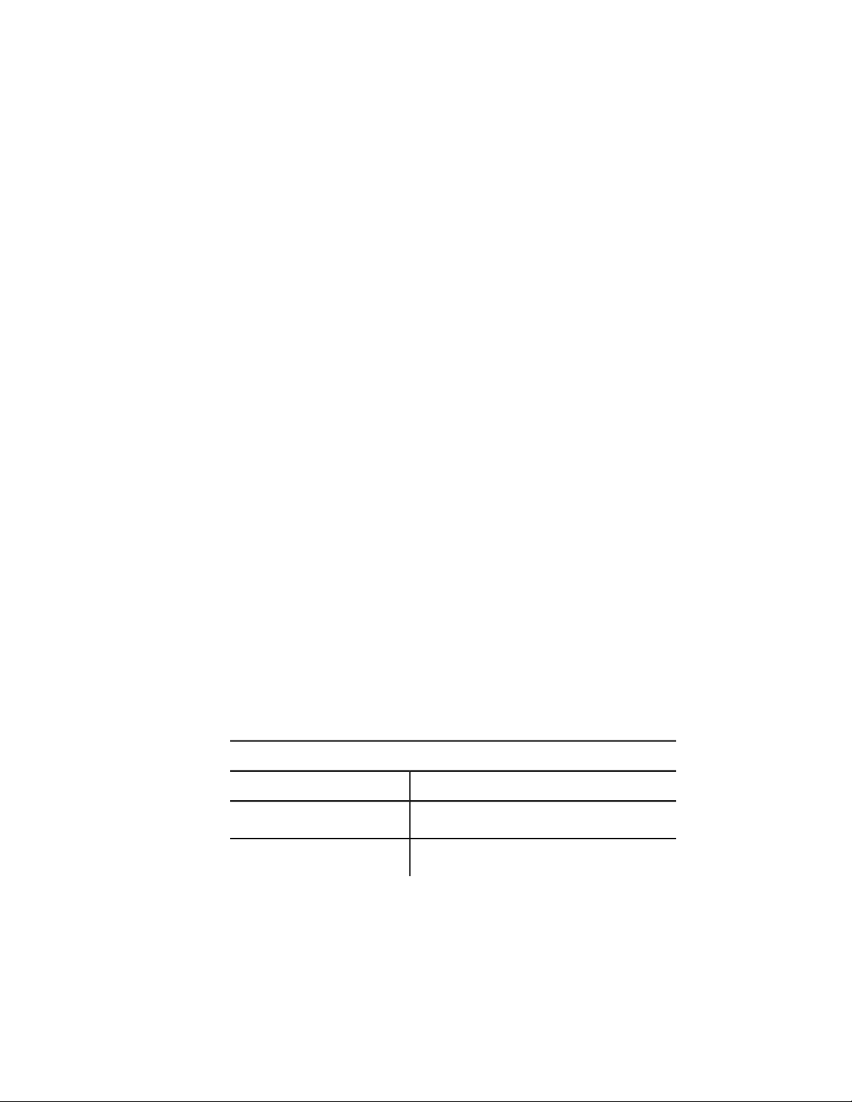
Filtering for Extended Data
Using the ssgetfilter-list, you can select all entities containing extended data
for a particular application. (See Extended Data—xdata (page 106).) To do this,
use the -3 group code, as shown in the following example:
(ssget "X" '((0 . "CIRCLE") (-3 ("APPNAME"))))
This code will select all circles that include extended data for the "APPNAME"
application. If more than one application name is included in the -3 group's
list, an AND operation is implied and the entity must contain extended data
for all of the specified applications. So, the following statement would select
all circles with extended data for both the "APP1" and "APP2" applications:
(ssget "X" '((0 . "CIRCLE") (-3 ("APP1")("APP2"))))
Wild-card matching is permitted, so either of the following statements will
select all circles with extended data for either or both of these applications.
(ssget "X" '((0 . "CIRCLE") (-3 ("APP[12]"))))
(ssget "X" '((0 . "CIRCLE") (-3 ("APP1,APP2"))))
Relational Tests
Unless otherwise specified, an equivalency is implied for each item in the
filter-list. For numeric groups (integers, reals, points, and vectors), you can
specify other relations by including a special -4 group code that specifies a
relational operator. The value of a -4 group is a string indicating the test
operator to be applied to the next group in the filter-list.
The following selects all circles with a radius (group code 40) greater than or
equal to 2.0:
(ssget "X" '((0 . "CIRCLE") (-4 . ">=") (40 . 2.0)))
The possible relational operators are shown in the following table:
Relational operators for selection set filter lists
DescriptionOperator
Anything goes (always true)"*"
Equals"="
80 | Chapter 2 Using the AutoLISP Language
Page 87

Relational operators for selection set filter lists
DescriptionOperator
Not equal to"!="
Not equal to"/="
Not equal to"<>"
Less than"<"
Less than or equal to"<="
Greater than">"
Greater than or equal to">="
Bitwise AND (integer groups only)"&"
Bitwise masked equals (integer groups only)"&="
The use of relational operators depends on the kind of group you are testing:
■ All relational operators except for the bitwise operators ("&" and "&=") are
valid for both real- and integer-valued groups.
■ The bitwise operators "&" and "&=" are valid only for integer-valued groups.
The bitwise AND, "&", is true if ((integer_group & filter) /= 0)—that is, if any
of the bits set in the mask are also set in the integer group. The bitwise
masked equals, "&=", is true if ((integer_group & filter) = filter)—that is, if all
bits set in the mask are also set in the integer_group (other bits might be set
in the integer_group but are not checked).
■ For point groups, the X, Y, and Z tests can be combined into a single string,
with each operator separated by commas (for example, ">,>,*"). If an
operator is omitted from the string (for example, "=,<>" leaves out the Z
test), then the “anything goes” operator, "*", is assumed.
■ Direction vectors (group type 210) can be compared only with the operators
"*", "=", and "!=" (or one of the equivalent “not equal” strings).
Using AutoLISP to Manipulate AutoCAD Objects | 81
Page 88
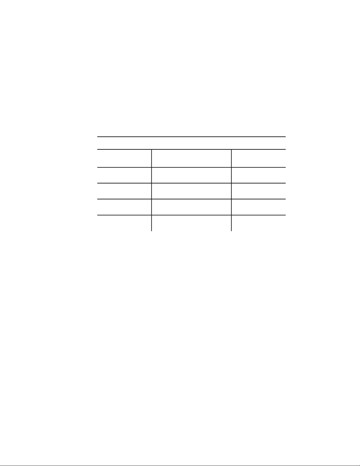
■ You cannot use the relational operators with string groups; use wild-card
tests instead.
Logical Grouping of Filter Tests
You can also test groups by creating nested Boolean expressions that use the
logical grouping operators shown in the following table:
Grouping operators for selection set filter lists
operator
EnclosesStarting
The grouping operators are specified by -4 groups, like the relational operators.
They are paired and must be balanced correctly in the filter list or the ssget
call will fail. An example of grouping operators in a filter list follows:
(ssget "X"
'(
(-4 . "<OR")
(-4 . "<AND")
(0 . "CIRCLE")
(40 . 1.0)
(-4 . "AND>")
(-4 . "<AND")
(0 . "LINE")
(8 . "ABC")
(-4 . "AND>")
(-4 . "OR>")
)
)
Ending
operator
"AND>"One or more operands"<AND"
"OR>"One or more operands"<OR"
"XOR>"Two operands"<XOR"
"NOT>"One operand"<NOT"
82 | Chapter 2 Using the AutoLISP Language
Page 89

This code selects all circles with a radius of 1.0 plus all lines on layer "ABC".
The grouping operators are not case-sensitive; for example, you can specify
"and>", "<or", instead of "AND>", "<OR".
Grouping operators are not allowed within the -3 group. Multiple application
names specified in a -3 group use an implied AND operator. If you want to
test for extended data using other grouping operators, specify separate -3
groups and group them as desired. To select all circles having extended data
for either application "APP1" or "APP2" but not both, enter the following:
(ssget "X"
'((0 . "CIRCLE")
(-4 . "<XOR")
(-3 ("APP1"))
(-3 ("APP2"))
(-4 . "XOR>")
)
)
You can simplify the coding of frequently used grouping operators by setting
them equal to a symbol. The previous example could be rewritten as follows
(notice that in this example you must explicitly quote each list):
(setq <xor '(-4 . "<XOR")
xor> '(-4 . "XOR>") )
(ssget "X"
(list
'(0 . "CIRCLE")
<xor
'(-3 ("APP1"))
'(-3 ("APP2"))
xor>
)
)
As you can see, this method may not be sensible for short pieces of code but
can be beneficial in larger applications.
Selection Set Manipulation
Once a selection set has been created, you can add entities to it or remove
entities from it with the functions ssadd and ssdel. You can use the ssadd
function to create a new selection set, as shown in the following example.
The following code fragment creates a selection set that includes the first and
Using AutoLISP to Manipulate AutoCAD Objects | 83
Page 90

last entities in the current drawing (entnext and entlast are described later
in this chapter).
(setq fname (entnext)) ; Gets first entity in
the
; drawing.
(setq lname (entlast)) ; Gets last entity in the
; drawing.
(if (not fname)
(princ "\nNo entities in drawing. ")
(progn
(setq ourset (ssadd fname)) ; Creates a selection set
of the
; first entity.
(ssadd lname ourset) ; Adds the last entity to
the
; selection set.
)
)
The example runs correctly even if only one entity is in the database (in which
case both entnext and entlast set their arguments to the same entity name).
If ssadd is passed the name of an entity already in the selection set, it ignores
the request and does not report an error. The following function removes the
first entity from the selection set created in the previous example:
(ssdel fname ourset)
If there is more than one entity in the drawing (that is, if fname and lname are
not equal), then the selection set ourset contains only lname, the last entity
in the drawing.
The function sslength returns the number of entities in a selection set, and
ssmemb tests whether a particular entity is a member of a selection set. Finally,
the function ssname returns the name of a particular entity in a selection set,
using an index to the set (entities in a selection set are numbered from 0).
The following code shows calls to ssname:
(setq sset (ssget)) ; Prompts the user to create
a
(setq ent1 (ssname sset 0)) ; Gets the name of the first
84 | Chapter 2 Using the AutoLISP Language
; selection set.
; entity in sset.
Page 91

(setq ent4 (ssname sset 3)) ; Gets the name of the fourth
; entity in sset.
(if (not ent4)
(princ "\nNeed to select at least four entities. ")
)
(setq ilast (sslength sset)) ; Finds index of the last
entity
; in sset.
; Gets the name of the
; last entity in sset.
(setq lastent (ssname sset (1- ilast)))
Regardless of how entities are added to a selection set, the set never contains
duplicate entities. If the same entity is added more than once, the later
additions are ignored. Therefore, sslength accurately returns the number of
distinct entities in the specified selection set.
Passing Selection Sets between AutoLISP and ObjectARX Applications
When passing selection sets between AutoLISP and ObjectARX applications,
the following should be observed:
If a selection set is created in AutoLISP and stored in an AutoLISP variable,
then overwritten by a value returned from an ObjectARX application, the
original selection set is eligible for garbage collection (it is freed at the next
automatic or explicit garbage collection).
This is true even if the value returned from the ObjectARX application was
the original selection set. In the following example, if the adsfunc ObjectARX
function returns the same selection set it was fed as an argument, then this
selection set will be eligible for garbage collection even though it is still
assigned to the same variable.
(setq var1 (ssget))
(setq var1 (adsfunc var1))
If you want the original selection set to be protected from garbage collection,
then you must not assign the return value of the ObjectARX application to
the AutoLISP variable that already references the selection set. Changing the
previous example prevents the selection set referenced by var1 from being
eligible for garbage collection.
Using AutoLISP to Manipulate AutoCAD Objects | 85
Page 92

(setq var1 (ssget))
(setq var2 (adsfunc var1))
Object Handling
AutoLISP provides functions for handling objects. The object-handling
functions are organized into two categories: functions that retrieve the entity
name of a particular object, and functions that retrieve or modify entity data.
See Object-Handling Functions (page 143) in AutoLISP Function Synopsis, (page
119) for a complete list of the object-handling functions.
Entity Name Functions
To operate on an object, an AutoLISP application must obtain its entity name
for use in subsequent calls to the entity data or selection set functions. Two
functions described in this section, entsel and nentsel, return not only the
entity's name but additional information for the application's use.
Both functions require the AutoCAD user to select an object interactively by
picking a point on the graphics screen. All the other entity name functions
can retrieve an entity even if it is not visible on the screen or if it is on a frozen
layer. The entsel function prompts the user to select an object by picking a
point on the graphics screen, and entsel returns both the entity name and
the value of the point selected. Some entity operations require knowledge of
the point by which the object was selected. Examples from the set of existing
AutoCAD commands include: BREAK, TRIM, and EXTEND. The nentsel
function is described in detail in Entity Context and Coordinate Transform
Data (page 88). These functions accept keywords if they are preceded by a call
to initget.
The entnext function retrieves entity names sequentially. If entnext is called
with no arguments, it returns the name of the first entity in the drawing
database. If its argument is the name of an entity in the current drawing,
entnext returns the name of the succeeding entity.
The following code fragment illustrates how ssadd can be used in conjunction
with entnext to create selection sets and add members to an existing set.
(setq e1 (entnext))
(if (not e1) ; Sets e1 to name of first
entity.
86 | Chapter 2 Using the AutoLISP Language
Page 93

(princ "\nNo entities in drawing. ")
(progn
(setq ss (ssadd)) ; Sets ss to a null selection
set.
(ssadd e1 ss) ; Returns selection set ss
with
; e1 added.
(setq e2 (entnext e1)) ; Gets entity following e1.
(ssadd e2 ss) ; Adds e2 to selection set
ss.
)
)
The entlast function retrieves the name of the last entity in the database. The
last entity is the most recently created main entity, so entlast can be called
to obtain the name of an entity that has just been created with a call to
command.
You can set the entity name returned by entnext to the same variable name
passed to this function. This “walks” a single entity name variable through
the database, as shown in the following example:
(setq one_ent (entnext)) ; Gets name of first
entity.
(while one_ent
.
. ; Processes new entity.
.
(setq one_ent (entnext one_ent))
) ; Value of one_ent is
now nil.
Entity Handles and Their Uses
The handent function retrieves the name of an entity with a specific handle.
As with entity names, handles are unique within a drawing. However, an
entity's handle is constant throughout its life. AutoLISP applications that
manipulate a specific database can use handent to obtain the current name
of an entity they must use. You can use the LIST command to get the handle
of a selected object.
Using AutoLISP to Manipulate AutoCAD Objects | 87
Page 94

The following code fragment uses handent to obtain and display an entity
name.
(if (not (setq e1 (handent "5a2")))
(princ "\nNo entity with that handle exists. ")
(princ e1)
)
In one particular editing session, this code fragment might display the
following:
<Entity name: 60004722>
In another editing session with the same drawing, the fragment might display
an entirely different number. But in both cases the code would be accessing
the same entity.
The handent function has an additional use. Entities can be deleted from the
database with entdel (see Entity Context and Coordinate Transform Data
(page 88)). The entities are not purged until the current drawing ends. This
means that handent can recover the names of deleted entities, which can
then be restored to the drawing by a second call to entdel.
NOTE Handles are provided for block definitions, including subentities.
Entities in drawings that are cross-referenced by way of XREF Attach are not
actually part of the current drawing; their handles are unchanged but cannot
be accessed by handent. However, when drawings are combined by means of
INSERT, INSERT *, XREF Bind (XBIND), or partial DXFIN, the handles of
entities in the incoming drawing are lost, and incoming entities are assigned
new handle values to ensure each handle in the current drawing remains
unique.
Entity Context and Coordinate Transform Data
The nentsel and nentselp functions are similar to entsel, except they return
two additional values to handle entities nested within block references.
Another difference between these functions is that when the user responds
to a nentsel call by selecting a complex entity or a complex entity is selected
by nentselp, these functions return the entity name of the selected subentity
and not the complex entity's header, as entsel does.
88 | Chapter 2 Using the AutoLISP Language
Page 95

For example, when the user selects a 3D polyline, nentsel returns a vertex
subentity instead of the polyline header. To retrieve the polyline header, the
application must use entnext to step forward to the seqend subentity, and
then obtain the name of the header from the seqend subentity's -2 group. The
same applies when the user selects attributes in a nested block reference.
Selecting an attribute within a block reference returns the name of the attribute
and the pick point. When the selected object is a component of a block
reference other than an attribute, nentsel returns a list containing the following
elements:
■ The selected entity's name.
■ A list containing the coordinates of the point used to pick the object.
■ The Model to World Transformation Matrix. This is a list consisting of
four sublists, each of which contains a set of coordinates. This matrix can
be used to transform the entity definition data points from an internal
coordinate system called the model coordinate system (MCS), to the World
Coordinate System (WCS). The insertion point of the block that contains
the selected entity defines the origin of the MCS. The orientation of the
UCS when the block is created determines the direction of the MCS axes.
■ A list containing the entity name of the block that contains the selected
object. If the selected object is in a nested block (a block within a block),
the list also contains the entity names of all blocks in which the selected
object is nested, starting with the innermost block and continuing outward
until the name of the block that was inserted in the drawing is reported.
The list returned from selecting a block with nentsel is summarized as follows:
(<Entity Name: ename1> ; Name of entity.
(Px Py Pz) ; Pick point.
( (X0 Y0 Z0) ; Model to World Transformation
Matrix.
(X1 Y1 Z1)
(X2 Y2 Z2)
(X3 Y3 Z3)
)
(<Entity name: ename2> ; Name of most deeply nested
block
. ; containing selected object.
.
.
<Entity name: enamen>) ; Name of outermost block
) ; containing selected object.
Using AutoLISP to Manipulate AutoCAD Objects | 89
Page 96

In the following example, create a block to use with the nentsel function.
Command: line
Specify first point: 1,1
Specify next point or [Undo]: 3,1
Specify next point or [Undo]: 3,3
Specify next point or [Close/Undo]: 1,3
Specify next point or [Close/Undo]: c
Command: -block
Enter block name or [?]: square
Specify insertion base point: 2,2
Select objects: Select the four lines you just drew
Select objects: Enter
Then, insert the block in a UCS rotated 45 degrees about the Z axis:
Command: ucs
Current ucs name: *WORLD*
Enter
option[New/Move/orthoGraphic/Prev/Restore/Save/Del/Apply/?/World]
<World>: z
Specify rotation angle about Z axis <0>: 45
Command: -insert
Enter block name or [?]: square
Specify insertion point or
[Scale/X/Y/Z/Rotate/PScale/PX/PY/PZ/PRotate]:7,0
Enter X scale factor, specify opposite corner, or [Corner/XYZ]
<1>: Enter
Enter Y scale factor <use X scale factor>: Enter
Specify rotation angle <0>: Enter
Use nentsel to select the lower-left side of the square.
(setq ndata (nentsel))
This code sets ndata equal to a list similar to the following:
(<Entity Name: 400000a0> ; Entity name.
(6.46616 -1.0606 0.0) ; Pick point.
((0.707107 0.707107 0.0) ; Model to World
(-0.707107 0.707107 0.0) ; Transformation Matrix.
(0.0 -0.0 1.0)
(4.94975 4.94975 0.0)
)
(<Entity name:6000001c>) ; Name of block containing
90 | Chapter 2 Using the AutoLISP Language
Page 97

; selected object.
)
Once you obtain the entity name and the Model to World Transformation
Matrix, you can transform the entity definition data points from the MCS to
the WCS. Use entget and assoc on the entity name to obtain the definition
points expressed in MCS coordinates. The Model to World Transformation
Matrix returned by nentsel is a 4×3 matrix—passed as an array of four
points—that uses the convention that a point is a row rather than a column.
The transformation is described by the following matrix multiplication:
So the equations for deriving the new coordinates are as follows:
The Mij, where 0 le; i, j le; 2, are the Model to World Transformation Matrix
coordinates; X, Y, Z is the entity definition data point expressed in MCS
coordinates, and X', Y', Z' is the resulting entity definition data point expressed
in WCS coordinates.
To transform a vector rather than a point, do not add the translation vector
(M30 M31 M32 from the fourth column of the transformation matrix).
NOTE This is the only AutoLISP function that uses a matrix of this type. The
nentselp function is preferred to nentsel because it returns a matrix similar to
those used by other AutoLISP and ObjectARX functions .
Using the entity name previously obtained with nentsel, the following example
illustrates how to obtain the MCS start point of a line (group code 10)
contained in a block definition:
Command: (setq edata (assoc 10 (entget (car ndata))))
Using AutoLISP to Manipulate AutoCAD Objects | 91
Page 98

(10 -1.0 1.0 0.0)
The following statement stores the Model to World Transformation Matrix
sublist in the symbolmatrix.
Command: (setq matrix (caddr ndata))
((0.707107 0.707107 0.0) ; X transformation
(-0.707107 0.707107 0.0) ; Y transformation
(0.0 -0.0 1.0) ; Z transformation
(4.94975 4.94975 0.0) ; Displacement from WCS origin
)
The following command applies the transformation formula forX ' to change
the X coordinate of the start point of the line from an MCS coordinate to a
WCS coordinate:
(setq answer
(+ ; add:
(* (car (nth 0 matrix))(cadr edata)) ; M00 * X
(* (car (nth 1 matrix))(caddr edata)) ; M10 * Y
(* (car (nth 2 matrix))(cadddr edata)) ; M20 * Z
(car (nth 3 matrix)) ; M30
)
)
This statement returns 3.53553, the WCSX coordinate of the start point of
the selected line.
Entity Access Functions
The entity access functions are relatively slow. It is best to get the contents of
a particular entity (or symbol table entry) once and keep that information
stored in memory, rather than repeatedly ask AutoCAD for the same data. Be
sure the data remains valid. If the user has an opportunity to alter the entity
or symbol table entry, you should reissue the entity access function to ensure
the validity of the data.
Entity Data Functions
The functions described in this section operate on entity data and can be used
to modify the current drawing database.
92 | Chapter 2 Using the AutoLISP Language
Page 99

Deleting an Entity
The entdel function deletes a specified entity. The entity is not purged from
the database until the end of the current drawing session, so if the application
calls entdel a second time during that session and specifies the same entity,
the entity is undeleted.
Attributes and old-style polyline vertices cannot be deleted independently of
their parent entities. The entdel function operates only on main entities. If
you need to delete an attribute or vertex, you can use command to invoke
the AutoCAD ATTEDIT or PEDIT commands.
Obtaining Entity Information
The entget function returns the definition data of a specified entity. The data
is returned as a list. Each item in the list is specified by a DXF group code. The
first item in the list contains the entity's current name.
In this example, the following (default) conditions apply to the current
drawing:
■ Layer is 0
■ Linetype is CONTINUOUS
■ Elevation is 0
The user has drawn a line with the following sequence of commands:
Command: line
From point: 1,2
To point: 6,6
To point: Enter
An AutoLISP application can retrieve and print the definition data for the line
by using the following AutoLISP function:
(defun C:PRINTDXF ( )
(setq ent (entlast)) ; Set ent to last entity.
(setq entl (entget ent)) ; Set entl to association list
of
; last entity.
(setq ct 0) ; Set ct (a counter) to 0.
(textpage) ; Switch to the text screen.
(princ "\nentget of last entity:")
Using AutoLISP to Manipulate AutoCAD Objects | 93
Page 100

(repeat (length entl) ; Repeat for number of members
in list:
(print (nth ct entl)) ; Print a newline, then each
list
; member.
(setq ct (1+ ct)) ; Increments the counter by one.
)
(princ) ; Exit quietly.
)
This would print the following:
entget of last entity:
(-1 . <Entity name: 1bbd1c8>)
(0 . "LINE")
(330 . <Entity name: 1bbd0c8>)
(5 . "69")
(100 . "AcDbEntity")
(67 . 0)
(410 . "Model")
(8 . "0")
(100 . "AcDbLine")
(10 1.0 2.0 0.0)
(11 6.0 6.0 0.0)
(210 0.0 0.0 1.0)
The -1 item at the start of the list contains the name of the entity. The entmod
function, which is described in this section, uses the name to identify the
entity to be modified. The individual dotted pairs that represent the values
can be extracted by using assoc with the cdr function.
Sublists for points are not represented as dotted pairs like the rest of the values
returned. The convention is that the cdr of the sublist is the group's value.
Because a point is a list of two or three reals, the entire group is a three- (or
four-) element list. The cdr of the group is the list representing the point, so
the convention that cdr always returns the value is preserved.
The codes for the components of the entity are those used by DXF. As with
DXF, the entity header items (color, linetype, thickness, the attributes-follow
flag, and the entity handle) are returned only if they have values other than
the default. Unlike DXF, optional entity definition fields are returned whether
or not they equal their defaults and whether or not associated X, Y, and Z
coordinates are returned as a single point variable, rather than as separate X
(10), Y (20), and Z (30) groups.
94 | Chapter 2 Using the AutoLISP Language
 Loading...