

Page 1

AutoCAD 2011 for Mac
User's Guide
September 2010
Page 2

©
2010 Autodesk, Inc. All Rights Reserved. Except as otherwise permitted by Autodesk, Inc., this publication, or parts thereof, may not be
reproduced in any form, by any method, for any purpose.
Certain materials included in this publication are reprinted with the permission of the copyright holder.
Trademarks
The following are registered trademarks or trademarks of Autodesk, Inc., and/or its subsidiaries and/or affiliates in the USA and other countries:
3DEC (design/logo), 3December, 3December.com, 3ds Max, Algor, Alias, Alias (swirl design/logo), AliasStudio, Alias|Wavefront (design/logo),
ATC, AUGI, AutoCAD, AutoCAD Learning Assistance, AutoCAD LT, AutoCAD Simulator, AutoCAD SQL Extension, AutoCAD SQL Interface,
Autodesk, Autodesk Envision, Autodesk Intent, Autodesk Inventor, Autodesk Map, Autodesk MapGuide, Autodesk Streamline, AutoLISP, AutoSnap,
AutoSketch, AutoTrack, Backburner, Backdraft, Built with ObjectARX (logo), Burn, Buzzsaw, CAiCE, Civil 3D, Cleaner, Cleaner Central, ClearScale,
Colour Warper, Combustion, Communication Specification, Constructware, Content Explorer, Dancing Baby (image), DesignCenter, Design
Doctor, Designer's Toolkit, DesignKids, DesignProf, DesignServer, DesignStudio, Design Web Format, Discreet, DWF, DWG, DWG (logo), DWG
Extreme, DWG TrueConvert, DWG TrueView, DXF, Ecotect, Exposure, Extending the Design Team, Face Robot, FBX, Fempro, Fire, Flame, Flare,
Flint, FMDesktop, Freewheel, GDX Driver, Green Building Studio, Heads-up Design, Heidi, HumanIK, IDEA Server, i-drop, ImageModeler, iMOUT,
Incinerator, Inferno, Inventor, Inventor LT, Kaydara, Kaydara (design/logo), Kynapse, Kynogon, LandXplorer, Lustre, MatchMover, Maya,
Mechanical Desktop, Moldflow, Moonbox, MotionBuilder, Movimento, MPA, MPA (design/logo), Moldflow Plastics Advisers, MPI, Moldflow
Plastics Insight, MPX, MPX (design/logo), Moldflow Plastics Xpert, Mudbox, Multi-Master Editing, Navisworks, ObjectARX, ObjectDBX, Open
Reality, Opticore, Opticore Opus, Pipeplus, PolarSnap, PortfolioWall, Powered with Autodesk Technology, Productstream, ProjectPoint, ProMaterials,
RasterDWG, RealDWG, Real-time Roto, Recognize, Render Queue, Retimer,Reveal, Revit, Showcase, ShowMotion, SketchBook, Smoke, Softimage,
Softimage|XSI (design/logo), Sparks, SteeringWheels, Stitcher, Stone, StudioTools, ToolClip, Topobase, Toxik, TrustedDWG, ViewCube, Visual,
Visual LISP, Volo, Vtour, Wire, Wiretap, WiretapCentral, XSI, and XSI (design/logo).
All other brand names, product names or trademarks belong to their respective holders.
Disclaimer
THIS PUBLICATION AND THE INFORMATION CONTAINED HEREIN IS MADE AVAILABLE BY AUTODESK, INC. "AS IS." AUTODESK, INC. DISCLAIMS
ALL WARRANTIES, EITHER EXPRESS OR IMPLIED, INCLUDING BUT NOT LIMITED TO ANY IMPLIED WARRANTIES OF MERCHANTABILITY OR
FITNESS FOR A PARTICULAR PURPOSE REGARDING THESE MATERIALS.
Published by:
Autodesk, Inc.
111 McInnis Parkway
San Rafael, CA 94903, USA
Page 3

Contents
Get Information . . . . . . . . . . . . . . . . . . . . . . . 1
Chapter 1 Find the Information You Need . . . . . . . . . . . . . . . . . . 3
Access and Search the Product Help . . . . . . . . . . . . . . . . . . . . 3
Learn the Product . . . . . . . . . . . . . . . . . . . . . . . . . . . . . . 4
View the Product Readme . . . . . . . . . . . . . . . . . . . . . . . . . 5
Join the Customer Involvement Program . . . . . . . . . . . . . . . . . 6
Chapter 2 Get Information from Drawings . . . . . . . . . . . . . . . . . . 7
Obtain General Drawing Information . . . . . . . . . . . . . . . . . . . 7
The User Interface . . . . . . . . . . . . . . . . . . . . . . 9
Chapter 3 Start a Command . . . . . . . . . . . . . . . . . . . . . . . . . 11
Parts of the User Interface . . . . . . . . . . . . . . . . . . . . . . . . . 11
The Menu Bar . . . . . . . . . . . . . . . . . . . . . . . . . . . . . . . 12
The Tool Sets Palette . . . . . . . . . . . . . . . . . . . . . . . . . . . . 13
The Command Line . . . . . . . . . . . . . . . . . . . . . . . . . . . . 15
Overview of Using the Command Line . . . . . . . . . . . . . . . 15
Enter Commands on the Command Line . . . . . . . . . . . . . 17
Enter System Variables on the Command Line . . . . . . . . . . . 18
iii
Page 4

Switch Between Dialog Boxes and the Command Line . . . . . . 20
View and Edit Within the Command History . . . . . . . . . . . 21
Work with Shortcut Menus . . . . . . . . . . . . . . . . . . . . . . . . 22
Chapter 4 Control the Drawing Area Interface . . . . . . . . . . . . . . . 25
Interface Themes and Background Color . . . . . . . . . . . . . . . . . 25
Cursors in the Drawing Area . . . . . . . . . . . . . . . . . . . . . . . 26
Selection Style . . . . . . . . . . . . . . . . . . . . . . . . . . . . . . . 27
The UCS Icon . . . . . . . . . . . . . . . . . . . . . . . . . . . . . . . 28
Viewport Label Menus . . . . . . . . . . . . . . . . . . . . . . . . . . 29
The ViewCube Tool . . . . . . . . . . . . . . . . . . . . . . . . . . . . 30
The Coordinates Display . . . . . . . . . . . . . . . . . . . . . . . . . 31
Model Space and Layouts . . . . . . . . . . . . . . . . . . . . . . . . . 32
Chapter 5 Control Status, Layers, Properties, and Content . . . . . . . . . 35
The Status Bar . . . . . . . . . . . . . . . . . . . . . . . . . . . . . . . 35
The Layers Palette . . . . . . . . . . . . . . . . . . . . . . . . . . . . . 36
The Properties Inspector . . . . . . . . . . . . . . . . . . . . . . . . . 38
The Content Palette . . . . . . . . . . . . . . . . . . . . . . . . . . . . 40
Chapter 6 Customize the Drawing Environment . . . . . . . . . . . . . . 43
Set Interface Options . . . . . . . . . . . . . . . . . . . . . . . . . . . 43
Set Up the Drawing Area . . . . . . . . . . . . . . . . . . . . . . 43
Specify the Behavior of Palettes . . . . . . . . . . . . . . . . . . . 48
Customize Startup . . . . . . . . . . . . . . . . . . . . . . . . . . . . . 49
Start and Save Drawings . . . . . . . . . . . . . . . . . . 51
Chapter 7 Start a Drawing . . . . . . . . . . . . . . . . . . . . . . . . . . 53
Overview of Starting a New Drawing . . . . . . . . . . . . . . . . . . . 53
Specify Units and Unit Formats . . . . . . . . . . . . . . . . . . . . . . 54
Determine the Units of Measurement . . . . . . . . . . . . . . . 54
Set the Unit Format Conventions . . . . . . . . . . . . . . . . . . 56
Use a Drawing Template File . . . . . . . . . . . . . . . . . . . . . . . 58
Add Identifying Information to Drawings . . . . . . . . . . . . . . . . 59
Chapter 8 Open or Save a Drawing . . . . . . . . . . . . . . . . . . . . . 61
Open a Drawing . . . . . . . . . . . . . . . . . . . . . . . . . . . . . . 61
Work with Multiple Open Drawings . . . . . . . . . . . . . . . . . . . 64
Preview Open Drawings and Layouts . . . . . . . . . . . . . . . . 64
Switch Between Open Drawings . . . . . . . . . . . . . . . . . . 65
Switch Between Layouts in the Current Drawing . . . . . . . . . 66
iv | Contents
Page 5

Transfer Information between Open Drawings . . . . . . . . . . . 67
Save a Drawing . . . . . . . . . . . . . . . . . . . . . . . . . . . . . . 67
Find a Drawing File . . . . . . . . . . . . . . . . . . . . . . . . . . . . 72
Specify Search Paths and File Locations . . . . . . . . . . . . . . . . . . 73
Chapter 9 Repair, Restore, or Recover Drawing Files . . . . . . . . . . . . 75
Repair a Damaged Drawing File . . . . . . . . . . . . . . . . . . . . . . 75
Create and Restore Backup Files . . . . . . . . . . . . . . . . . . . . . . 77
Control the Drawing Views . . . . . . . . . . . . . . . . . 79
Chapter 10 Change Views . . . . . . . . . . . . . . . . . . . . . . . . . . . 81
Pan or Zoom a View . . . . . . . . . . . . . . . . . . . . . . . . . . . . 81
Save and Restore Views . . . . . . . . . . . . . . . . . . . . . . . . . . 84
Control the 3D Projection Style . . . . . . . . . . . . . . . . . . . . . . 85
Overview of Parallel and Perspective Views . . . . . . . . . . . . . 85
Define a Perspective Projection (DVIEW) . . . . . . . . . . . . . . 87
Define a Parallel Projection . . . . . . . . . . . . . . . . . . . . . 88
Choose Preset 3D Views . . . . . . . . . . . . . . . . . . . . . . . 89
Define a 3D View with Coordinate Values or Angles . . . . . . . . 90
Change to a View of the XY Plane . . . . . . . . . . . . . . . . . 91
Shade a Model and Use Edge Effects . . . . . . . . . . . . . . . . . . . 92
Use a Visual Style to Display Your Model . . . . . . . . . . . . . . 92
Customize a Visual Style . . . . . . . . . . . . . . . . . . . . . . 95
Control Performance . . . . . . . . . . . . . . . . . . . . . . . . 105
Chapter 11 Use Viewing Tools . . . . . . . . . . . . . . . . . . . . . . . . 107
Specify 3D Views . . . . . . . . . . . . . . . . . . . . . . . . . . . . . 107
Overview of 3D Views . . . . . . . . . . . . . . . . . . . . . . . 107
Use 3D Navigation Tools . . . . . . . . . . . . . . . . . . . . . . 108
Create a 3D Dynamic View (DVIEW) . . . . . . . . . . . . . . . 110
Use ViewCube . . . . . . . . . . . . . . . . . . . . . . . . . . . . . . 111
Overview of ViewCube . . . . . . . . . . . . . . . . . . . . . . . 111
ViewCube Menu . . . . . . . . . . . . . . . . . . . . . . . . . . 113
Reorient the View of a Model with ViewCube . . . . . . . . . . 115
Change the UCS with ViewCube . . . . . . . . . . . . . . . . . 119
Chapter 12 Display Multiple Views in Model Space . . . . . . . . . . . . . 121
Set Model Space Viewports . . . . . . . . . . . . . . . . . . . . . . . 121
Select and Use the Current Viewport . . . . . . . . . . . . . . . . . . 124
Save and Restore Model Layout Viewport Arrangements . . . . . . . . 125
Contents | v
Page 6

Organize Drawings and Layouts . . . . . . . . . . . . . 127
Chapter 13 Create Single-View Drawings (Model Space) . . . . . . . . . . 129
Quick Start for Model Space Drafting . . . . . . . . . . . . . . . . . . 129
Draw, Scale, and Annotate in Model Space . . . . . . . . . . . . . . . 131
Chapter 14 Create Multiple-View Drawing Layouts (Paper Space) . . . . . 137
Quick Start for Layouts . . . . . . . . . . . . . . . . . . . . . . . . . . 137
Understand the Layout Process . . . . . . . . . . . . . . . . . . . . . 139
Work with Model Space and Paper Space . . . . . . . . . . . . . . . . 141
Work on the Model Layout . . . . . . . . . . . . . . . . . . . . 141
Work on a Named Layout . . . . . . . . . . . . . . . . . . . . . 142
Access Model Space from a Layout Viewport . . . . . . . . . . . 144
Create and Modify Layout Viewports . . . . . . . . . . . . . . . . . . 145
Control Views in Layout Viewports . . . . . . . . . . . . . . . . . . . 147
Scale Views in Layout Viewports . . . . . . . . . . . . . . . . . 147
Control Visibility in Layout Viewports . . . . . . . . . . . . . . 149
Scale Linetypes in Layout Viewports . . . . . . . . . . . . . . . 153
Align Views in Layout Viewports . . . . . . . . . . . . . . . . . 154
Rotate Views in Layout Viewports . . . . . . . . . . . . . . . . . 155
Reuse Layouts and Layout Settings . . . . . . . . . . . . . . . . . . . 157
Create and Modify Objects . . . . . . . . . . . . . . . . 159
Chapter 15 Control the Properties of Objects . . . . . . . . . . . . . . . . 161
Work with Object Properties . . . . . . . . . . . . . . . . . . . . . . . 161
Overview of Object Properties . . . . . . . . . . . . . . . . . . . 161
Display and Change the Properties of Objects . . . . . . . . . . 163
Copy Properties Between Objects . . . . . . . . . . . . . . . . . 164
Work with Layers . . . . . . . . . . . . . . . . . . . . . . . . . . . . 165
Overview of Layers . . . . . . . . . . . . . . . . . . . . . . . . . 165
Use Layers to Manage Complexity . . . . . . . . . . . . . . . . 167
Create and Name Layers . . . . . . . . . . . . . . . . . . . . . . 169
Change Layer Settings and Layer Properties . . . . . . . . . . . . 171
Override Layer Properties in Viewports . . . . . . . . . . . . . . 173
Work with Colors . . . . . . . . . . . . . . . . . . . . . . . . . . . . 176
Set the Current Color . . . . . . . . . . . . . . . . . . . . . . . 176
Change the Color of an Object . . . . . . . . . . . . . . . . . . 177
Use Color Books . . . . . . . . . . . . . . . . . . . . . . . . . . 179
Work with Linetypes . . . . . . . . . . . . . . . . . . . . . . . . . . . 180
Overview of Linetypes . . . . . . . . . . . . . . . . . . . . . . . 180
Load Linetypes . . . . . . . . . . . . . . . . . . . . . . . . . . . 181
Set the Current Linetype . . . . . . . . . . . . . . . . . . . . . . 182
vi | Contents
Page 7

Change the Linetype of an Object . . . . . . . . . . . . . . . . . 183
Control Linetype Scale . . . . . . . . . . . . . . . . . . . . . . . 184
Display Linetypes on Short Segments and Polylines . . . . . . . 185
Control Lineweights . . . . . . . . . . . . . . . . . . . . . . . . . . . 186
Overview of Lineweights . . . . . . . . . . . . . . . . . . . . . 186
Display Lineweights . . . . . . . . . . . . . . . . . . . . . . . . 188
Set the Current Lineweight . . . . . . . . . . . . . . . . . . . . 189
Change the Lineweight of an Object . . . . . . . . . . . . . . . 191
Control the Display Properties of Certain Objects . . . . . . . . . . . 192
Control the Display of Polylines, Hatches, Gradient Fills,
Lineweights, and Text . . . . . . . . . . . . . . . . . . . . . . 192
Control the Transparency of Objects . . . . . . . . . . . . . . . 194
Control How Overlapping Objects Are Displayed . . . . . . . . . 196
Control the Display of Objects . . . . . . . . . . . . . . . . . . 197
Chapter 16 Use Precision Tools . . . . . . . . . . . . . . . . . . . . . . . . 199
Use Coordinates and Coordinate Systems (UCS) . . . . . . . . . . . . 199
Overview of Coordinate Entry . . . . . . . . . . . . . . . . . . . 199
Enter 2D Coordinates . . . . . . . . . . . . . . . . . . . . . . . 200
Enter 3D Coordinates . . . . . . . . . . . . . . . . . . . . . . . 205
Understand the User Coordinate System (UCS) . . . . . . . . . . 210
Specify Workplanes in 3D (UCS) . . . . . . . . . . . . . . . . . 214
Assign User Coordinate System Orientations to Viewports . . . . 219
Control the Display of the User Coordinate System Icon . . . . . 221
Use Dynamic Input . . . . . . . . . . . . . . . . . . . . . . . . . . . 223
Snap to Locations on Objects (Object Snaps) . . . . . . . . . . . . . . 226
Use Object Snaps . . . . . . . . . . . . . . . . . . . . . . . . . . 226
The Object Snap Menu . . . . . . . . . . . . . . . . . . . . . . 229
Set Visual Aids for Object Snaps (AutoSnap) . . . . . . . . . . . 229
Override Object Snap Settings . . . . . . . . . . . . . . . . . . . 230
Restrict Cursor Movement . . . . . . . . . . . . . . . . . . . . . . . . 232
Adjust Grid and Grid Snap . . . . . . . . . . . . . . . . . . . . . 232
Use Orthogonal Locking (Ortho Mode) . . . . . . . . . . . . . . 237
Use Polar Tracking and PolarSnap . . . . . . . . . . . . . . . . . 238
Lock an Angle for One Point (Angle) . . . . . . . . . . . . . . . 241
Combine or Offset Points and Coordinates . . . . . . . . . . . . . . . 241
Combine Coordinate Values (Coordinate Filters) . . . . . . . . . 241
Track to Points on Objects (Object Snap Tracking) . . . . . . . . 244
Track to Offset Point Locations (Tracking) . . . . . . . . . . . . 246
Specify Distances . . . . . . . . . . . . . . . . . . . . . . . . . . . . . 247
Enter Direct Distances . . . . . . . . . . . . . . . . . . . . . . . 247
Offset from Temporary Reference Points . . . . . . . . . . . . . 248
Specify Intervals on Objects . . . . . . . . . . . . . . . . . . . . 248
Extract Geometric Information from Objects . . . . . . . . . . . . . . 252
Obtain Distances, Angles, and Point Locations . . . . . . . . . . 252
Obtain Area and Mass Properties Information . . . . . . . . . . 253
Contents | vii
Page 8

Use a Calculator . . . . . . . . . . . . . . . . . . . . . . . . . . . . . 257
Use the Command Prompt Calculator . . . . . . . . . . . . . . 257
Chapter 17 Draw Geometric Objects . . . . . . . . . . . . . . . . . . . . . 261
Draw Linear Objects . . . . . . . . . . . . . . . . . . . . . . . . . . . 261
Draw Lines . . . . . . . . . . . . . . . . . . . . . . . . . . . . . 261
Draw Polylines . . . . . . . . . . . . . . . . . . . . . . . . . . . 262
Draw Rectangles and Polygons . . . . . . . . . . . . . . . . . . 265
Draw Multiline Objects . . . . . . . . . . . . . . . . . . . . . . 267
Draw Freehand Sketches . . . . . . . . . . . . . . . . . . . . . . 269
Draw Curved Objects . . . . . . . . . . . . . . . . . . . . . . . . . . 270
Draw Arcs . . . . . . . . . . . . . . . . . . . . . . . . . . . . . 270
Draw Circles . . . . . . . . . . . . . . . . . . . . . . . . . . . . 274
Draw Polyline Arcs . . . . . . . . . . . . . . . . . . . . . . . . . 275
Draw Donuts . . . . . . . . . . . . . . . . . . . . . . . . . . . . 279
Draw Ellipses . . . . . . . . . . . . . . . . . . . . . . . . . . . . 280
Draw Splines . . . . . . . . . . . . . . . . . . . . . . . . . . . . 281
Draw Helixes . . . . . . . . . . . . . . . . . . . . . . . . . . . . 285
Draw Construction and Reference Geometry . . . . . . . . . . . . . . 286
Draw Reference Points . . . . . . . . . . . . . . . . . . . . . . . 286
Draw Construction Lines (and Rays) . . . . . . . . . . . . . . . 287
Create and Combine Areas (Regions) . . . . . . . . . . . . . . . . . . 289
Create Revision Clouds . . . . . . . . . . . . . . . . . . . . . . . . . 291
Chapter 18 Change Existing Objects . . . . . . . . . . . . . . . . . . . . 293
Select Objects . . . . . . . . . . . . . . . . . . . . . . . . . . . . . . . 293
Select Objects Individually . . . . . . . . . . . . . . . . . . . . . 293
Select Multiple Objects . . . . . . . . . . . . . . . . . . . . . . 295
Prevent Objects from Being Selected . . . . . . . . . . . . . . . 298
Select Objects by Properties . . . . . . . . . . . . . . . . . . . . 299
Customize Object Selection . . . . . . . . . . . . . . . . . . . . 300
Group Objects . . . . . . . . . . . . . . . . . . . . . . . . . . . 304
Correct Mistakes . . . . . . . . . . . . . . . . . . . . . . . . . . . . . 307
Erase Objects . . . . . . . . . . . . . . . . . . . . . . . . . . . . . . . 309
Cut, Copy, and Paste with the Clipboard . . . . . . . . . . . . . . . . 310
Modify Objects . . . . . . . . . . . . . . . . . . . . . . . . . . . . . . 311
Choose a Method to Modify Objects . . . . . . . . . . . . . . . 311
Edit Objects with Grips . . . . . . . . . . . . . . . . . . . . . . 313
Move or Rotate Objects . . . . . . . . . . . . . . . . . . . . . . 321
Copy, Offset, or Mirror Objects . . . . . . . . . . . . . . . . . . 325
Change the Size and Shape of Objects . . . . . . . . . . . . . . 337
Fillet, Chamfer, Break, or Join Objects . . . . . . . . . . . . . . . 344
Modify Complex Objects . . . . . . . . . . . . . . . . . . . . . . . . 353
Disassociate Compound Objects (Explode) . . . . . . . . . . . . 353
Modify Polylines . . . . . . . . . . . . . . . . . . . . . . . . . . 355
viii | Contents
Page 9

Modify Splines . . . . . . . . . . . . . . . . . . . . . . . . . . . 359
Modify Helixes . . . . . . . . . . . . . . . . . . . . . . . . . . . 363
Modify Multilines . . . . . . . . . . . . . . . . . . . . . . . . . 364
Chapter 19 Add Constraints to Geometry . . . . . . . . . . . . . . . . . . 367
Overview of Constraints . . . . . . . . . . . . . . . . . . . . . . . . . 367
Constrain Objects Geometrically . . . . . . . . . . . . . . . . . . . . 371
Overview of Geometric Constraints . . . . . . . . . . . . . . . . 371
Apply or Remove Geometric Constraints . . . . . . . . . . . . . 373
Display and Verify Geometric Constraints . . . . . . . . . . . . 379
Modify Objects with Geometric Constraints Applied . . . . . . . 381
Infer Geometric Constraints . . . . . . . . . . . . . . . . . . . . 384
Constrain Distances and Angles between Objects . . . . . . . . . . . . 386
Overview of Dimensional Constraints . . . . . . . . . . . . . . 386
Apply Dimensional Constraints . . . . . . . . . . . . . . . . . . 389
Control the Display of Dimensional Constraints . . . . . . . . . 394
Modify Objects with Dimensional Constraints Applied . . . . . 395
Constrain a Design with Formulas and Equations . . . . . . . . . . . 398
Overview of Formulas and Equations . . . . . . . . . . . . . . . 398
Control Geometry with Parameters . . . . . . . . . . . . . . . . 399
Define and Reference Blocks . . . . . . . . . . . . . . . 403
Chapter 20 Work with Blocks . . . . . . . . . . . . . . . . . . . . . . . . . 405
Overview of Blocks . . . . . . . . . . . . . . . . . . . . . . . . . . . . 405
Insert Blocks . . . . . . . . . . . . . . . . . . . . . . . . . . . . . . . 407
Work with Dynamic Blocks in Drawings . . . . . . . . . . . . . . . . 409
Overview of Dynamic Blocks . . . . . . . . . . . . . . . . . . . 409
Remove Block Definitions . . . . . . . . . . . . . . . . . . . . . . . . 411
Chapter 21 Create and Modify Blocks . . . . . . . . . . . . . . . . . . . . 413
Define Blocks . . . . . . . . . . . . . . . . . . . . . . . . . . . . . . . 413
Create Blocks Within a Drawing . . . . . . . . . . . . . . . . . . 413
Create Drawing Files for Use as Blocks . . . . . . . . . . . . . . 414
Control the Color and Linetype Properties in Blocks . . . . . . . 416
Nest Blocks . . . . . . . . . . . . . . . . . . . . . . . . . . . . . 418
Create Block Libraries . . . . . . . . . . . . . . . . . . . . . . . 419
Attach Data to Blocks (Block Attributes) . . . . . . . . . . . . . . . . . 420
Overview of Block Attributes . . . . . . . . . . . . . . . . . . . 420
Define Block Attributes . . . . . . . . . . . . . . . . . . . . . . 423
Extract Data from Block Attributes . . . . . . . . . . . . . . . . 425
Extract Block Attribute Data (Advanced) . . . . . . . . . . . . . 426
Modify Blocks . . . . . . . . . . . . . . . . . . . . . . . . . . . . . . 431
Contents | ix
Page 10

Modify a Block Definition . . . . . . . . . . . . . . . . . . . . . 431
Modify the Data in Block Attributes . . . . . . . . . . . . . . . . 433
Modify a Block Attribute Definition . . . . . . . . . . . . . . . . 434
Disassemble a Block Reference (Explode) . . . . . . . . . . . . . 437
Work with 3D Models . . . . . . . . . . . . . . . . . . . 439
Chapter 22 Create 3D Models . . . . . . . . . . . . . . . . . . . . . . . . 441
Overview of 3D Modeling . . . . . . . . . . . . . . . . . . . . . . . . 441
Create Solids and Surfaces from Lines and Curves . . . . . . . . . . . 446
Overview of Creating Solids and Surfaces . . . . . . . . . . . . . 446
Create a Solid or Surface by Extruding . . . . . . . . . . . . . . 450
Create a Solid or Surface by Sweeping . . . . . . . . . . . . . . . 453
Create a Solid or Surface by Lofting . . . . . . . . . . . . . . . . 456
Create a Solid or Surface by Revolving . . . . . . . . . . . . . . 459
Create Solids . . . . . . . . . . . . . . . . . . . . . . . . . . . . . . . 461
Overview of Creating 3D Solids . . . . . . . . . . . . . . . . . . 461
Create 3D Solid Primitives . . . . . . . . . . . . . . . . . . . . . 465
Create a Polysolid . . . . . . . . . . . . . . . . . . . . . . . . . 475
Create 3D Solids from Objects . . . . . . . . . . . . . . . . . . . 477
Combine or Slice 3D Objects . . . . . . . . . . . . . . . . . . . 481
Check 3D Models for Interferences . . . . . . . . . . . . . . . . 484
Create Surfaces . . . . . . . . . . . . . . . . . . . . . . . . . . . . . . 485
Overview of Creating Surfaces . . . . . . . . . . . . . . . . . . . 486
Create Procedural Surfaces . . . . . . . . . . . . . . . . . . . . . 491
Create NURBS Surfaces . . . . . . . . . . . . . . . . . . . . . . . 501
Create Associative Surfaces . . . . . . . . . . . . . . . . . . . . 505
Create Meshes . . . . . . . . . . . . . . . . . . . . . . . . . . . . . . 511
Overview of Creating Meshes . . . . . . . . . . . . . . . . . . . 511
Create 3D Mesh Primitives . . . . . . . . . . . . . . . . . . . . 515
Construct Meshes from Other Objects . . . . . . . . . . . . . . 528
Create Meshes by Conversion . . . . . . . . . . . . . . . . . . . 534
Create Custom Mesh (Legacy) . . . . . . . . . . . . . . . . . . . 537
Create Wireframe Models . . . . . . . . . . . . . . . . . . . . . . . . 542
Add 3D Thickness to Objects . . . . . . . . . . . . . . . . . . . . . . 544
Chapter 23 Modify 3D Models . . . . . . . . . . . . . . . . . . . . . . . . 547
Overview of Modifying 3D Objects . . . . . . . . . . . . . . . . . . . 547
Use Gizmos to Modify Objects . . . . . . . . . . . . . . . . . . . . . . 549
Overview of Using Gizmos . . . . . . . . . . . . . . . . . . . . 549
Use the Gizmos . . . . . . . . . . . . . . . . . . . . . . . . . . 551
Move 3D Objects . . . . . . . . . . . . . . . . . . . . . . . . . . 554
Rotate 3D Objects . . . . . . . . . . . . . . . . . . . . . . . . . 556
Scale 3D Objects . . . . . . . . . . . . . . . . . . . . . . . . . . 558
x | Contents
Page 11

Use Grips to Modify Solids and Surfaces . . . . . . . . . . . . . . . . 561
Use 3D Subobject Grips . . . . . . . . . . . . . . . . . . . . . . 561
Cycle Through and Filter Subobjects . . . . . . . . . . . . . . . 564
Use Grips to Edit 3D Solids and Surfaces . . . . . . . . . . . . . 567
Modify 3D Subobjects . . . . . . . . . . . . . . . . . . . . . . . . . . 570
Move, Rotate, and Scale 3D Subobjects . . . . . . . . . . . . . . 570
Modify Faces on 3D Objects . . . . . . . . . . . . . . . . . . . . 573
Modify Edges on 3D Objects . . . . . . . . . . . . . . . . . . . . 575
Modify Vertices on 3D Objects . . . . . . . . . . . . . . . . . . 579
Work with Complex 3D Solids and Surfaces . . . . . . . . . . . . . . 581
Display Original Forms of Composite Solids . . . . . . . . . . . 582
Modify Composite Solids and Surfaces . . . . . . . . . . . . . . 583
Shell and Remove Redundancies in 3D Objects . . . . . . . . . . 585
Press or Pull Bounded Areas . . . . . . . . . . . . . . . . . . . . 587
Add Edges and Faces to Solids . . . . . . . . . . . . . . . . . . . 588
Modify Properties of 3D Solid, Surface, and Mesh . . . . . . . . . . . 590
Modify Surfaces . . . . . . . . . . . . . . . . . . . . . . . . . . . . . 594
Overview of Modifying Surfaces . . . . . . . . . . . . . . . . . . 594
Trim and Untrim Surfaces . . . . . . . . . . . . . . . . . . . . . 596
Extend a Surface . . . . . . . . . . . . . . . . . . . . . . . . . . 598
Fillet a Surface . . . . . . . . . . . . . . . . . . . . . . . . . . . 599
Edit NURBS Surfaces . . . . . . . . . . . . . . . . . . . . . . . . 600
Analyze Surfaces . . . . . . . . . . . . . . . . . . . . . . . . . . 602
Modify Mesh Objects . . . . . . . . . . . . . . . . . . . . . . . . . . 610
Overview of Modifying Meshes . . . . . . . . . . . . . . . . . . 610
Change Mesh Smoothness Levels . . . . . . . . . . . . . . . . . 615
Refine Mesh Objects or Subobjects . . . . . . . . . . . . . . . . 619
Add Creases to Mesh . . . . . . . . . . . . . . . . . . . . . . . . 621
Modify Mesh Faces . . . . . . . . . . . . . . . . . . . . . . . . . 622
Create and Close Mesh Gaps . . . . . . . . . . . . . . . . . . . 626
Tips for Working with Mesh . . . . . . . . . . . . . . . . . . . . 627
Chapter 24 Create Sections and 2D Drawings from 3D Models . . . . . . . 635
Work with Sections . . . . . . . . . . . . . . . . . . . . . . . . . . . 635
Overview of Section Objects . . . . . . . . . . . . . . . . . . . . 635
Create Section Objects . . . . . . . . . . . . . . . . . . . . . . . 637
Modify a Section View . . . . . . . . . . . . . . . . . . . . . . . 640
Save and Publish Section Objects . . . . . . . . . . . . . . . . . 647
Create a Flattened View . . . . . . . . . . . . . . . . . . . . . . . . . 650
Annotate Drawings . . . . . . . . . . . . . . . . . . . . 653
Chapter 25 Work with Annotations . . . . . . . . . . . . . . . . . . . . . 655
Overview of Annotations . . . . . . . . . . . . . . . . . . . . . . . . 655
Contents | xi
Page 12

Scale Annotations . . . . . . . . . . . . . . . . . . . . . . . . . . . . 656
Overview of Scaling Annotations . . . . . . . . . . . . . . . . . 657
Set Annotation Scale . . . . . . . . . . . . . . . . . . . . . . . . 658
Create Annotative Objects . . . . . . . . . . . . . . . . . . . . . 660
Display Annotative Objects . . . . . . . . . . . . . . . . . . . . 670
Add and Modify Scale Representations . . . . . . . . . . . . . . 671
Set Orientation for Annotations . . . . . . . . . . . . . . . . . . . . . 673
Chapter 26 Hatches, Fills, and Wipeouts . . . . . . . . . . . . . . . . . . . 675
Overview of Hatch Patterns and Fills . . . . . . . . . . . . . . . . . . 675
Specify Hatch and Fill Areas . . . . . . . . . . . . . . . . . . . . . . . 680
Control the Appearance of Hatches . . . . . . . . . . . . . . . . . . . 684
Choose a Hatch Pattern or Fill . . . . . . . . . . . . . . . . . . . 685
Control the Hatch Origin Point . . . . . . . . . . . . . . . . . . 689
Control the Scale of Hatch Patterns . . . . . . . . . . . . . . . . 691
Set Property Overrides for Hatches and Fills . . . . . . . . . . . 692
Control the Display of Hatch Boundaries . . . . . . . . . . . . . 694
Control the Draw Order of Hatches and Fills . . . . . . . . . . . 696
Modify Hatches and Fills . . . . . . . . . . . . . . . . . . . . . . . . . 697
Modify Hatch Properties . . . . . . . . . . . . . . . . . . . . . . 697
Modify Hatch Alignment, Scale, and Rotation . . . . . . . . . . 698
Reshape a Hatch or Fill . . . . . . . . . . . . . . . . . . . . . . 699
Re-create the Boundary of a Hatch or Fill . . . . . . . . . . . . . 701
Create a Blank Area to Cover Objects . . . . . . . . . . . . . . . . . . 702
Chapter 27 Notes and Labels . . . . . . . . . . . . . . . . . . . . . . . . . 705
Overview of Notes and Labels . . . . . . . . . . . . . . . . . . . . . . 705
Create Text . . . . . . . . . . . . . . . . . . . . . . . . . . . . . . . . 706
Overview of Creating Text . . . . . . . . . . . . . . . . . . . . . 706
Create Single-Line Text . . . . . . . . . . . . . . . . . . . . . . 708
Create Multiline Text . . . . . . . . . . . . . . . . . . . . . . . 711
Create and Edit Columns in Multiline Text . . . . . . . . . . . . 722
Import Text from External Files . . . . . . . . . . . . . . . . . . 723
Create Leaders . . . . . . . . . . . . . . . . . . . . . . . . . . . . . . 723
Overview of Leader Objects . . . . . . . . . . . . . . . . . . . . 724
Create and Modify Leaders . . . . . . . . . . . . . . . . . . . . 725
Work with Leader Styles . . . . . . . . . . . . . . . . . . . . . . 728
Add Content to a Leader . . . . . . . . . . . . . . . . . . . . . . 729
Use Fields in Text . . . . . . . . . . . . . . . . . . . . . . . . . . . . . 732
Insert Fields . . . . . . . . . . . . . . . . . . . . . . . . . . . . 733
Update Fields . . . . . . . . . . . . . . . . . . . . . . . . . . . . 735
Use Hyperlinks in Fields . . . . . . . . . . . . . . . . . . . . . . 736
Work with Text Styles . . . . . . . . . . . . . . . . . . . . . . . . . . 738
Overview of Text Styles . . . . . . . . . . . . . . . . . . . . . . 738
Assign Text Fonts . . . . . . . . . . . . . . . . . . . . . . . . . 740
xii | Contents
Page 13

Set Text Height . . . . . . . . . . . . . . . . . . . . . . . . . . . 746
Set Text Obliquing Angle . . . . . . . . . . . . . . . . . . . . . 747
Set Horizontal or Vertical Text Orientation . . . . . . . . . . . . 748
Change Text . . . . . . . . . . . . . . . . . . . . . . . . . . . . . . . 749
Overview of Changing Text . . . . . . . . . . . . . . . . . . . . 749
Change Single-Line Text . . . . . . . . . . . . . . . . . . . . . . 750
Change Multiline Text . . . . . . . . . . . . . . . . . . . . . . . 751
Find and Replace Text . . . . . . . . . . . . . . . . . . . . . . . 753
Check Spelling . . . . . . . . . . . . . . . . . . . . . . . . . . . . . . 754
Chapter 28 Tables . . . . . . . . . . . . . . . . . . . . . . . . . . . . . . . 757
Create and Modify Tables . . . . . . . . . . . . . . . . . . . . . . . . 757
Work with Table Styles . . . . . . . . . . . . . . . . . . . . . . . . . . 760
Add Text and Blocks to Tables . . . . . . . . . . . . . . . . . . . . . . 762
Use Formulas in Table Cells . . . . . . . . . . . . . . . . . . . . . . . 764
Chapter 29 Dimensions and Tolerances . . . . . . . . . . . . . . . . . . . 767
Understand Basic Concepts of Dimensioning . . . . . . . . . . . . . . 767
Overview of Dimensioning . . . . . . . . . . . . . . . . . . . . 767
Parts of a Dimension . . . . . . . . . . . . . . . . . . . . . . . . 769
Associative Dimensions . . . . . . . . . . . . . . . . . . . . . . 771
Use Dimension Styles . . . . . . . . . . . . . . . . . . . . . . . . . . 773
Overview of Dimension Styles . . . . . . . . . . . . . . . . . . . 773
Compare Dimension Styles and Variables . . . . . . . . . . . . . 774
Control Dimension Geometry . . . . . . . . . . . . . . . . . . . 775
Control Dimension Text . . . . . . . . . . . . . . . . . . . . . . 783
Control Dimension Values . . . . . . . . . . . . . . . . . . . . . 792
Set the Scale for Dimensions . . . . . . . . . . . . . . . . . . . . . . . 801
Create Dimensions . . . . . . . . . . . . . . . . . . . . . . . . . . . . 803
Create Linear Dimensions . . . . . . . . . . . . . . . . . . . . . 803
Create Radial Dimensions . . . . . . . . . . . . . . . . . . . . . 809
Create Angular Dimensions . . . . . . . . . . . . . . . . . . . . 814
Create Ordinate Dimensions . . . . . . . . . . . . . . . . . . . 816
Create Arc Length Dimensions . . . . . . . . . . . . . . . . . . 818
Modify Existing Dimensions . . . . . . . . . . . . . . . . . . . . . . . 819
Modify A Dimension . . . . . . . . . . . . . . . . . . . . . . . . 819
Apply a New Dimension Style to Existing Dimensions . . . . . . 827
Override a Dimension Style . . . . . . . . . . . . . . . . . . . . 828
Modify Dimension Text . . . . . . . . . . . . . . . . . . . . . . 830
Modify Dimension Geometry . . . . . . . . . . . . . . . . . . . 832
Change Dimension Associativity . . . . . . . . . . . . . . . . . 835
Add Geometric Tolerances . . . . . . . . . . . . . . . . . . . . . . . . 837
Overview of Geometric Tolerances . . . . . . . . . . . . . . . . 837
Material Conditions . . . . . . . . . . . . . . . . . . . . . . . . 839
Datum Reference Frames . . . . . . . . . . . . . . . . . . . . . 840
Contents | xiii
Page 14

Projected Tolerance Zones . . . . . . . . . . . . . . . . . . . . . 840
Composite Tolerances . . . . . . . . . . . . . . . . . . . . . . . 841
Plot and Publish Drawings . . . . . . . . . . . . . . . . 843
Chapter 30 Specify Settings for Plotting . . . . . . . . . . . . . . . . . . . 845
Save Plot Settings as Named Page Setups . . . . . . . . . . . . . . . . 845
Reuse Named Page Setups . . . . . . . . . . . . . . . . . . . . . . . . 846
Specify Page Setup Settings . . . . . . . . . . . . . . . . . . . . . . . 848
Select a Printer or Plotter for a Layout . . . . . . . . . . . . . . . 848
Select a Paper Size for a Layout . . . . . . . . . . . . . . . . . . 848
Determine the Drawing Orientation of a Layout . . . . . . . . . 849
Set the Plot Area of a Layout . . . . . . . . . . . . . . . . . . . . 850
Adjust the Plot Offset of a Layout . . . . . . . . . . . . . . . . . 851
Set the Plot Scale for a Layout . . . . . . . . . . . . . . . . . . . 852
Set the Lineweight Scale for a Layout . . . . . . . . . . . . . . . 853
Select a Plot Style Table for a Layout . . . . . . . . . . . . . . . 853
Set Shaded Viewport and Plot Options for a Layout . . . . . . . 854
Chapter 31 Print or Plot Drawings . . . . . . . . . . . . . . . . . . . . . . 857
Overview of Plotting . . . . . . . . . . . . . . . . . . . . . . . . . . . 857
Use a Page Setup to Specify Plot Settings . . . . . . . . . . . . . . . . 860
Select a Printer or Plotter . . . . . . . . . . . . . . . . . . . . . . . . 860
Specify the Area to Plot . . . . . . . . . . . . . . . . . . . . . . . . . 861
Set Paper Size . . . . . . . . . . . . . . . . . . . . . . . . . . . . . . . 862
Position the Drawing on the Paper . . . . . . . . . . . . . . . . . . . 863
Specify the Printable Area . . . . . . . . . . . . . . . . . . . . . 863
Set the Position of the Plot . . . . . . . . . . . . . . . . . . . . 864
Set Drawing Orientation . . . . . . . . . . . . . . . . . . . . . 864
Control How Objects Are Plotted . . . . . . . . . . . . . . . . . . . . 865
Set Plot Scale . . . . . . . . . . . . . . . . . . . . . . . . . . . . 865
Set Shaded Viewport Options . . . . . . . . . . . . . . . . . . . 867
Set Options for Plotted Objects . . . . . . . . . . . . . . . . . . 870
Use Plot Styles to Control Plotted Objects . . . . . . . . . . . . 871
Use Color-Dependent Plot Style Tables . . . . . . . . . . . . . . 874
Use Named Plot Style Tables . . . . . . . . . . . . . . . . . . . . 875
Preview a Plot . . . . . . . . . . . . . . . . . . . . . . . . . . . . . . 876
Plot Files to Other Formats . . . . . . . . . . . . . . . . . . . . . . . 877
Plot Adobe PDF Files . . . . . . . . . . . . . . . . . . . . . . . . 877
Share Data Between Files . . . . . . . . . . . . . . . . . 879
Chapter 32 Reference Other Drawing Files . . . . . . . . . . . . . . . . . 881
xiv | Contents
Page 15

Overview of Referenced Drawings (Xrefs) . . . . . . . . . . . . . . . . 881
Attach and Detach Referenced Drawings . . . . . . . . . . . . . . . . 883
Attach Drawing References (Xrefs) . . . . . . . . . . . . . . . . 883
Nest and Overlay Referenced Drawings . . . . . . . . . . . . . . 886
Set Paths to Referenced Drawings . . . . . . . . . . . . . . . . . 888
Detach Referenced Drawings . . . . . . . . . . . . . . . . . . . 889
Update and Archive Referenced Drawings . . . . . . . . . . . . . . . . 890
Update Referenced Drawing Attachments . . . . . . . . . . . . 890
Archive Drawings That Contain Referenced Drawings
(Bind) . . . . . . . . . . . . . . . . . . . . . . . . . . . . . . . 892
Clip External References and Blocks . . . . . . . . . . . . . . . . . . . 894
Edit Referenced Drawings . . . . . . . . . . . . . . . . . . . . . . . . 897
Edit a Referenced Drawing in a Separate Window . . . . . . . . 897
Resolve Referenced Drawing Errors . . . . . . . . . . . . . . . . . . . 898
Resolve Missing External References . . . . . . . . . . . . . . . 898
Resolve Circular External References . . . . . . . . . . . . . . . 899
Resolve Name Conflicts in External References . . . . . . . . . . 900
Track External Reference Operations (Log File) . . . . . . . . . . 901
Increase Performance with Large Referenced Drawings . . . . . . . . . 904
Overview of Demand Loading . . . . . . . . . . . . . . . . . . . 904
Unload Xrefs in Large Drawings . . . . . . . . . . . . . . . . . . 905
Set Paths for Temporary Xref File Copies . . . . . . . . . . . . . 905
Chapter 33 Work with Data in Other Formats . . . . . . . . . . . . . . . . 907
Import Other File Formats . . . . . . . . . . . . . . . . . . . . . . . . 907
Import ACIS SAT Files . . . . . . . . . . . . . . . . . . . . . . . 907
Convert DXF and DXB Files to DWG Format . . . . . . . . . . . 908
Attach Raster Image Files . . . . . . . . . . . . . . . . . . . . . . . . 908
Overview of Raster Images . . . . . . . . . . . . . . . . . . . . . 908
Attach, Scale, and Detach Raster Images . . . . . . . . . . . . . 910
Modify Raster Images and Image Boundaries . . . . . . . . . . . 913
Manage Raster Images . . . . . . . . . . . . . . . . . . . . . . . 917
Tune Raster Image Performance . . . . . . . . . . . . . . . . . . 920
Export Drawings to Other File Formats . . . . . . . . . . . . . . . . . 923
Export PDF Files . . . . . . . . . . . . . . . . . . . . . . . . . . 923
Export DXF Files . . . . . . . . . . . . . . . . . . . . . . . . . . 923
Export Raster Files . . . . . . . . . . . . . . . . . . . . . . . . . 924
Export PostScript Files . . . . . . . . . . . . . . . . . . . . . . . 925
Export ACIS SAT Files . . . . . . . . . . . . . . . . . . . . . . . 926
Export Stereolithography STL Files . . . . . . . . . . . . . . . . 926
Use Drawings from Different Versions and Applications . . . . . . . . 927
Work with Drawings in Earlier Releases . . . . . . . . . . . . . . 928
Save Drawings to Previous Drawing File Formats . . . . . . . . . 931
Work with AutoCAD Drawings in AutoCAD LT . . . . . . . . . . 934
Work with Custom and Proxy Objects . . . . . . . . . . . . . . 937
Contents | xv
Page 16

Collaborate with Others . . . . . . . . . . . . . . . . . 941
Chapter 34 Use the Internet for Collaboration . . . . . . . . . . . . . . . 943
Get Started with Internet Access . . . . . . . . . . . . . . . . . . . . . 943
Work with Drawing Files over the Internet . . . . . . . . . . . . . . . 944
Open and Save Drawing Files from the Internet . . . . . . . . . 944
Share Drawing Files Internationally . . . . . . . . . . . . . . . . 945
Access Buzzsaw for Project Collaboration . . . . . . . . . . . . . 947
Work with Xrefs over the Internet . . . . . . . . . . . . . . . . . 948
Render Drawings . . . . . . . . . . . . . . . . . . . . . 949
Chapter 35 Draw 2D Isometric Views . . . . . . . . . . . . . . . . . . . . 951
Set Isometric Grid and Snap . . . . . . . . . . . . . . . . . . . . . . . 951
Draw Isometric Circles . . . . . . . . . . . . . . . . . . . . . . . . . . 953
Chapter 36 Add Lighting to Your Model . . . . . . . . . . . . . . . . . . . 955
Overview of Lighting . . . . . . . . . . . . . . . . . . . . . . . . . . 955
Standard and Photometric Lighting Workflow . . . . . . . . . . . . . 958
Illuminate a Scene . . . . . . . . . . . . . . . . . . . . . . . . . . . . 960
Guidelines for Lighting . . . . . . . . . . . . . . . . . . . . . . 960
Use Point Lights . . . . . . . . . . . . . . . . . . . . . . . . . . 962
Use Spotlights . . . . . . . . . . . . . . . . . . . . . . . . . . . 965
Use Weblights . . . . . . . . . . . . . . . . . . . . . . . . . . . 967
Use Distant Lights . . . . . . . . . . . . . . . . . . . . . . . . . 976
Assigning a Shape to a Light . . . . . . . . . . . . . . . . . . . . 977
Adjust and Manipulate Lights . . . . . . . . . . . . . . . . . . . . . . 978
Control the Display of Lights . . . . . . . . . . . . . . . . . . . 978
Adjust Light Placement . . . . . . . . . . . . . . . . . . . . . . 979
Control Light Properties . . . . . . . . . . . . . . . . . . . . . . 982
Incorporate Luminaire Objects . . . . . . . . . . . . . . . . . . . . . 987
Chapter 37 Materials and Textures . . . . . . . . . . . . . . . . . . . . . . 989
Overview of Materials . . . . . . . . . . . . . . . . . . . . . . . . . . 989
Browse Material Library . . . . . . . . . . . . . . . . . . . . . . . . . 990
Chapter 38 Render 3D Objects for Realism . . . . . . . . . . . . . . . . . 993
Overview of Rendering . . . . . . . . . . . . . . . . . . . . . . . . . . 993
Prepare a Model for Rendering . . . . . . . . . . . . . . . . . . . . . 994
Understand Face Normals and Hidden Surfaces . . . . . . . . . . 994
Minimize Intersecting and Coplanar Faces . . . . . . . . . . . . 996
xvi | Contents
Page 17

Balance Mesh Density for Smooth Geometry . . . . . . . . . . . 998
Set Up the Renderer . . . . . . . . . . . . . . . . . . . . . . . . . . . 1001
Control the Rendering Environment . . . . . . . . . . . . . . 1001
Basics of Rendering . . . . . . . . . . . . . . . . . . . . . . . . . . . 1002
Render Views . . . . . . . . . . . . . . . . . . . . . . . . . . . 1002
Save and Redisplay Rendered Images . . . . . . . . . . . . . . . . . . 1003
Save a Rendered Image . . . . . . . . . . . . . . . . . . . . . . 1003
Redisplay a Rendered Image . . . . . . . . . . . . . . . . . . . 1004
Use Models with Other Applications . . . . . . . . . . . . . . . 1005
Glossary . . . . . . . . . . . . . . . . . . . . . . . . . . . . . 1007
Index . . . . . . . . . . . . . . . . . . . . . . . . . . . . . . 1035
Contents | xvii
Page 18

xviii
Page 19

Get Information
1
Page 20

2
Page 21

Find the Information You Need
There are various ways to find information about how to use this program, and multiple
resources are available.
This program is a powerful application with tools that help you work with a high level of
efficiency and productivity. You install this software with the Installation wizard that starts
automatically when you insert the product media.
This application is often intuitive, but when you do need to look something up, you can save
time and avoid frustration if you use the Help system to find information. The Help system
is organized in a structured design that makes information easy to locate.
1
Access and Search the Product Help
The Help system in AutoCAD for Mac uses a Web browser and is available online
and offline.
You can access the Help system by doing one of the following:
■ Press Fn-F1 or Cmd-/.
If you press Fn-F1 or Cmd-/ when a command is active, the appropriate help
topic is opened in the Web browser. Otherwise, the landing page of the Help
system is displayed.
■ On the Mac OS menu bar, click Help ➤ AutoCAD for Mac Help.
The landing page of the Help system is displayed.
■ In a dialog box, help the Help or ‘?’ button.
The help topic related to the dialog box is opened in the Web browser.
3
Page 22
Navigate Help
Each page of the help system is divided into four main areas:
■ Header - Contains the navigation links to the Home page along with links
that represent the path to the current topic. Along with navigation links,
the Search text box is also located in the header.
■ Left Side - Along the left side of a page is the table of contents that allow
you to navigate in the current guide. You can also find links sections on
the current page as well as related topics in the documentation set. When
on the Home page, the left side contains a listing of the guides in the
current documentation set.
■ Middle - The middle of the page contains the content for the current topic.
When on the Home page, the middle of the page contains links to the
main topics in the selected guide in the documentation set from the left
side.
■ Right Side - The right side of the page contains links that are related to
the current topic. These links come from Autodesk.com and are available
only when using the online version of the Help system.
Search Help
In the upper-right corner of each page is a Search text box. Enter a text string
to search on, and click the Search button or press Enter to begin the search.
The results of the search are displayed on a new page. The left side of the
results page lists the books that a search result was found in, while the right
side displays the results for the selected book. Click a book from the left side
to see additional serach results, or click a link from the search results to open
the associated topic.
Learn the Product
For the latest information about Autodesk training, visit
http://www.autodesk.com/training or contact your local Autodesk office.
-----Authorized Training Centers
4 | Chapter 1 Find the Information You Need
More than 1,200 ATC sites are available
worldwide to meet your needs for
discipline-specific, locally based training.
Page 23
Autodesk Official Training
Courseware
Autodesk Official Training Courseware (AOTC) is
technical training material developed by
-----
Autodesk. You can purchase AOTC from your
local reseller or distributor, or you can order it
online from the Autodesk Store.
Autodesk e-Learning for Autodesk Subscription
-----e-Learning
customers features interactive lessons organized
into product catalogs.
The Autodesk Developer (ADN) program provides
support for full-time, professional developers who
-----Autodesk Developer Network
want to build software based on Autodesk
products.
Autodesk Consulting provides services that help
set up processes and provide critical training that
-----Consulting
will help increase productivity so you can
capitalize on the power of your products.
View the Product Readme
You can find late-breaking information about this software in the Readme.
It is suggested that you read through the Readme for information about
recommended hardware, updated installation instructions, and known software
problems.
■ View the Readme
Visit the Partner Products & Services page for a
-----Partner Products and Services
list of resources available for your Autodesk
product and your industry.
View the Product Readme | 5
Page 24

Join the Customer Involvement Program
You are invited to help guide the direction of Autodesk design software.
If you participate in the Customer Involvement Program (CIP), specific
information about how you use AutoCAD for Mac is forwarded to Autodesk.
This information includes what features you use the most, problems that you
encounter, and other information helpful to the future direction of the
product.
See the following links for more information.
■ Learn more about the Autodesk Customer Involvement Program:
http://www.autodesk.com/cip
■ Read the Autodesk Privacy Statement: http://www.autodesk.com/cipprivacy
When you join, you will be able to view reports that can help you optimize
your use of AutoCAD for Mac.
To turn the CIP on or off
1 On the menu bar, click Help ➤ Customer Involvement Program.
2 In the Customer Involvement Program dialog box, choose whether you
want to start or stop participating.
3 Click OK.
6 | Chapter 1 Find the Information You Need
Page 25

Get Information from Drawings
You can retrieve general information from a drawing including identifying information and
the number of objects that it contains.
There are types of information stored in a drawing that are not specific to objects within the
drawing, but provide useful information to help you understand the behavior of the drawing,
the settings of system variables, the number of objects, descriptive information, and so on.
2
Obtain General Drawing Information
You can retrieve general information about the drawing file and its settings.
This information includes the following:
■ Custom descriptive information about the drawing (DWGPROPS)
■ General drawing settings (STATUS)
■ Amount of time spent in the drawing (TIME)
This information can help you document a drawing, displays a variety of drawing
settings such as the total number of objects in the drawing, and total amount
of time spent in the drawing file.
See also:
■ Enter System Variables on the Command Line on page 18
■ Add Identifying Information to Drawings on page 59
■ Extract Geometric Information from Objects on page 252
7
Page 26

■ Compare Dimension Styles and Variables on page 774
Quick Reference
Commands
DWGPROPS
Sets and displays the file properties of the current drawing.
SETVAR
Lists or changes the values of system variables.
STATUS
Displays drawing statistics, modes, and extents.
TIME
Displays the date and time statistics of a drawing.
System Variables
CDATE
Stores the current date and time in decimal format.
DATE
Stores the current date and time in Modified Julian Date format.
SAVENAME
Displays the file name and directory path of the most recently saved drawing.
8 | Chapter 2 Get Information from Drawings
Page 27

The User Interface
9
Page 28

10
Page 29
Start a Command
3
Use the menu bar, Tool Sets palette, and Command Line to access many frequently used
commands.
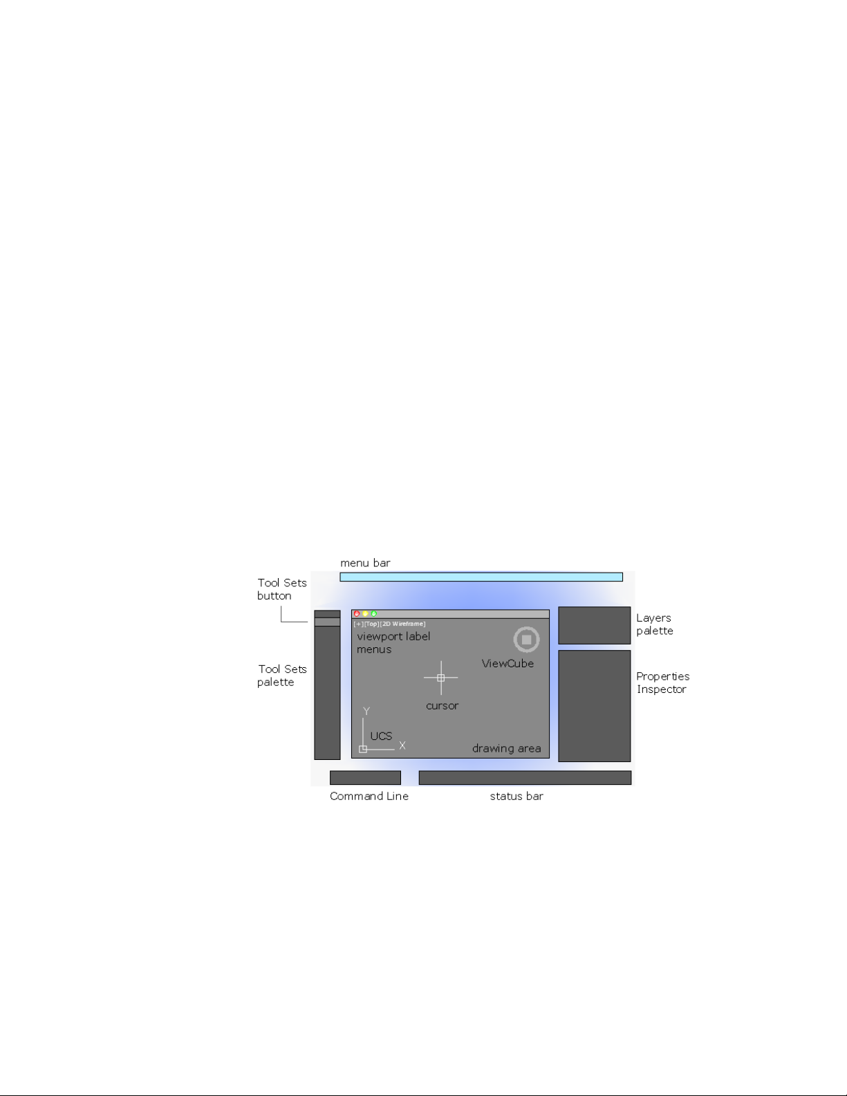
Parts of the User Interface
The default user interface displays palettes and bars around the drawing area.
Also, several controls are displayed within the drawing area.
The Search field displays at the top of the application menu. Search results can
include menu commands, basic tooltips, and command prompt text strings.
You can enter a search term in any language.
■ Cmd-1 turns the Tool Sets palette on and off
■ Cmd-2 turns the Content Libraries palette on and off
11
Page 30

■ Cmd-3 turns the Command Line on and off
■ Cmd-4 turns the Layers palette on and off
■ Cmd-5 turns the Properties Inspector on and off
■ Cmd-6 turns the Status bar on and off
■ Cmd-7 turns the References Manager palette on and off
■ Cmd-8 turns the Materials Browser palette on and off
■ Cmd-9 is not assigned
■ Cmd-0 turns all palettes and bars on and off
You can dock palettes by dragging them to the edge of your screen until a
blue line appears, and then dropping them into place. You can also undock
them by dragging and dropping.
Quick Reference
Commands
CUI
Manages the customized user interface elements in the product.
OPTIONS
Customizes the program settings.
The Menu Bar
The menu bar contains common commands organized into logical categories.
Use the menu bar when learning the product, or browsing for a command.
12 | Chapter 3 Start a Command
Page 31

Many, but not all commands are accessible from the menu bar. Less commonly
used commands can be entered in the Command Line. All available commands
are listed in the Help system under Command Reference.
Quick Reference
Commands
CUI
Manages the customized user interface elements in the product.
The Tool Sets Palette
The Tool Sets palette provides efficient access to AutoCAD commands.
The Search field displays at the top of the application menu. Search results
can include menu commands, basic tooltips, and command prompt text
strings. You can enter a search term in any language.
■ Tool flyouts
■ Tool groups
■ Tool sets
The Tool Sets Palette | 13
Page 32

Tool Flyouts
Some of the tools on the Tool Sets palette have a flyout indicator.
Click and hold the flyout to display several options for that command.
Tool Groups
The tools on the Tool Sets palette are organized into tool groups. Click the
arrow to display the entire tool group, which includes additional commands.
To make the tool group stay visible, click the lock icon at the bottom of the
tool group.
If you right-click the Tool Sets palette, a menu displays that you can use to
turn off any tool groups that you don’t need.
14 | Chapter 3 Start a Command
Page 33

Tool Sets
Click the Tool Sets button to display a list of alternate sets of commands based
on your current tasks. For example, clicking the Annotation tool set replaces
the commands in the Tool Sets palette with commands associated with
dimensioning.
Cmd-1 turns the Tool Sets palette on and off.
TIP Use the CUI editor to customize any tool set, or create your own tool sets.
Quick Reference
Commands
CUI
Manages the customized user interface elements in the product.
The Command Line
The Command Line provides a fast way to enter commands and system
variables directly using the keyboard.
Overview of Using the Command Line
By default, the Command Line is displayed in the lower-left corner of screen.
The Command Line | 15
Page 34

Using the keyboard, you can enter the following in the Command Line:
■ A command or command abbreviation called a command alias
■ The capitalized letters of an option for a command
■ A setting called a system variable that controls how the program operates
by default
Many advanced users prefer this method for speed. Also, the Command Line
displays prompts and error messages.
Cmd-3 turns the Command Line on and off.
Quick Reference
Commands
COMMANDLINE
Displays the Command Line window.
COMMANDLINEHIDE
Hides the Command Line window.
CUI
Manages the customized user interface elements in the product.
16 | Chapter 3 Start a Command
Page 35

Enter Commands on the Command Line
You can enter a command by using the keyboard. Some commands also have
abbreviated names called command aliases.
To enter a command by using the keyboard, type the full command name or
its command alias in the input area of the Command Line, and then press
Enter or Spacebar. The Command Line includes several controls.
For example, instead of entering circle to start the CIRCLE command, you can
enter c. Command aliases are defined in the acad.pgp file. To define your own
command aliases, see Create Command Aliases in the Customization Guide.
To find a command or system variable, type one or more of its beginning
letters in the Command Line and press Tab to cycle through all the possibilities.
Then, press Enter or Spacebar.
NOTE When Dynamic Input is turned on and is set to display dynamic prompts,
you can enter commands and options in tooltips near the cursor. Dynamic Input
can be turned on an off from the status bar.
Specify Command Options
When you enter a command in the Command Line, you see either a set of
options, a dialog box, or a palette. To specify an option displayed in the
Command line, enter the capitalized letters for the option. For example, when
you enter circle, the following prompt is displayed:
Specify center point for circle or [3P/2P/Ttr (tan tan radius)]:
You can specify the center point for the circle either by entering X,Y coordinate
values, or by using the pointing device to click a point in the drawing area.
To choose a different option, enter the letters capitalized in one of the options
in the brackets. You can enter uppercase or lowercase letters. For example, to
choose the three-point option (3P), enter 3p.
Enter Commands on the Command Line | 17
Page 36

Repeat and Cancel Commands
You can repeat the previous command by pressing Enter or Spacebar.
To repeat a recently used command, right-click in the Command Line or click
the drop-down arrow to the left of the command input area. This action
displays a shortcut menu with a list of recently used commands.
You can also repeat a recently used command by cycling through the
commands with Up Arrow and Down Arrow keys, and then pressing Enter.
To cancel any command in progress, press ESC.
See also:
■ Use Dynamic Input on page 223
■ Keyboard Shortcuts
■ Create Command Aliases
Quick Reference
Commands
COMMANDLINE
Displays the Command Line window.
COMMANDLINEHIDE
Hides the Command Line window.
CUI
Manages the customized user interface elements in the product.
Enter System Variables on the Command Line
System variables are settings that control how certain commands work.
Sometimes you use a system variable in order to change a setting. At other
times you use a system variable to display the current status.
With system variables, you can
■ Turn on or turn off features. For example, the GRIDMODE system variable
turns the grid display on and off when you change the value.
18 | Chapter 3 Start a Command
Page 37

■ Control the operation of a command. For example, the HPASSOC syatem
variable controls whether hatch patterns are associative by default.
■ Retrieve stored information about the current drawing and about the
program configuration. For example, CDATE is a read-only system variable
that stores the current date in decimal format. You can display the values
of read-only system variables, but you cannot change them.
Usually system variables are accessible from dialog boxes. You can change
their values either in a dialog box, directly in the Command Line, or
automatically in a script or custom program.
To change the setting of a system variable
1 In the Command Line, enter the system variable name. For example,
enter pickadd to change the style for selecting objects, whether selecting
objects automatically replaces the current selection set, or whether they
are added to the current selection set.
2 If necessary, press Fn+F1 to view the documentation for that system
variable.
3 Enter the setting that you want to use. In the example of PICKADD, enter
0, 1, or 2 to determine how you select multiple objects.
Quick Reference
Commands
COMMANDLINE
Displays the Command Line window.
COMMANDLINEHIDE
Hides the Command Line window.
CUI
Manages the customized user interface elements in the product.
SETVAR
Lists or changes the values of system variables.
Enter System Variables on the Command Line | 19
Page 38

Switch Between Dialog Boxes and the Command Line
You can display prompts on the command line instead of using a dialog box,
or switch back again. This option is useful primarily when using scripts.
Some functions are available both in the Command Line and in a dialog box.
In many cases, you can enter a hyphen before a command to suppress the
dialog box and display prompts in the Command Line instead.
For example, entering layer on the command line displays the Layer Properties
Manager. Entering -layer on the command line displays the equivalent
Command Line options.
Suppressing a dialog box is useful for familiar operation with earlier versions
of the program, and for using script files. There may be slight differences
between the options in the dialog box and those available in the Command
Line.
These system variables also affect the display of dialog boxes:
■ ATTDIA controls whether the INSERT command uses a dialog box for
entering block attribute values.
■ EXPERT controls whether certain warning dialog boxes are displayed.
■ FILEDIA controls the display of dialog boxes used with commands that
read and write files. For example, if FILEDIA is set to 1, SAVEAS displays
the Save Drawing As dialog box. If FILEDIA is set to 0, SAVEAS displays
prompts on the command line. The procedures in this documentation
assume that FILEDIA is set to 1. Even when FILEDIA is set to 0, you can
display a file dialog box by entering a tilde (~) at the first prompt.
FILEDIA and EXPERT are useful when you use scripts to run commands.
Quick Reference
Commands
COMMANDLINE
Displays the Command Line window.
COMMANDLINEHIDE
Hides the Command Line window.
20 | Chapter 3 Start a Command
Page 39

System Variables
ATTDIA
Controls whether the INSERT command uses a dialog box for attribute value
entry.
EXPERT
Controls whether certain prompts are issued.
FILEDIA
Suppresses display of file navigation dialog boxes.
View and Edit Within the Command History
You can copy text from the Command History to repeat commands.
You can expand and collapse the Command History in the Command Line
using the indicated control.
Within the Command History, use the Up Arrow and Down Arrow keys, the
scroll bar, or other scrolling method to locate and then highlight previously
entered commands, system variables, and text.
By default, pressing Cmd-C copies highlighted text to the Clipboard. Pressing
Cmd-V pastes text from the Clipboard to the Command Line.
To copy all the text in the Command History to the Clipboard, right-click and
select Copy History from the shortcut menu, or enter the COPYHIST command.
To save commands automatically to a log file starting with the next command,
enter the LOGFILEON command.
Quick Reference
Commands
COMMANDLINE
Displays the Command Line window.
View and Edit Within the Command History | 21
Page 40

COMMANDLINEHIDE
Hides the Command Line window.
COPYHIST
Hides the Command Line window.
LOGFILEOFF
Closes the command history log file opened by LOGFILEON.
LOGFILEON
Writes the contents of the command history to a file.
System Variables
LOGFILEMODE
Specifies whether the contents of the command history are written to a log
file.
LOGFILENAME
Specifies the path and name of the command history log file for the current
drawing.
LOGFILEPATH
Specifies the path for the command history log files for all drawings in a
session.
Work with Shortcut Menus
Display a shortcut menu for quick access to commands that are relevant to
your current activity.
The Search field displays at the top of the application menu. Search results
can include menu commands, basic tooltips, and command prompt text
strings. You can enter a search term in any language.
■ Display the controls for a user-interface element such as a palette, the
status bar, or the ViewCube
■ Control the command in progress, including command options, object
snaps, and canceling.
■ Display a list of recent input or repeat the last command entered
■ Cut, copy, and paste from the Clipboard
22 | Chapter 3 Start a Command
Page 41

■ Display a dialog box, such as Drafting Settings or Preferences
■ Undo the last command entered
In the Application Preferences dialog box (the OPTIONS command), you can
customize right-click behavior to be time sensitive, so that a quick right-click
acts the same as pressing Enter, and a longer right-click displays a shortcut
menu.
Quick Reference
Commands
CUI
Manages the customized user interface elements in the product.
OPTIONS
Customizes the program settings.
Work with Shortcut Menus | 23
Page 42

24
Page 43

Control the Drawing Area Interface
The drawing area includes several tools and controls for viewing and drawing operations. You
can adjust the display of these interface elements.
4
Interface Themes and Background Color
Many options are provided for customizing the look and feel of the product,
including the color of the icons and the background color of the drawing area.
The default color of the icons and palettes are dark gray. If you prefer, you can
change this theme to a light color.
The default background color of the drawing area is a medium gray, which is
optimum for displaying objects with different colors. Nevertheless, some people
prefer a white or a black background color depending on their tasks and
preferences.
See also:
■ Set Up the Drawing Area on page 43
To change the color of the user interface between dark and light
1 On the menu bar, click AutoCAD, and then Preferences.
2 In the Application Preferences dialog box, left column, click Look & Feel.
3 Under Interface Theme, click in the Themes box, and click either Dark or
Light.
4 Click OK.
25
Page 44

To change the background color of the drawing area in Model space
1 On the menu bar, click AutoCAD, and then Preferences.
2 In the Application Preferences dialog box, left column, click Look & Feel.
3 Under Interface Theme, click in the Model box, and then click a color,
or click Select Color.
The default dark gray background color has an RGB value of 33,40,48.
4 If you clicked Select Color, the Color Palette dialog box is displayed. At
the top of the dialog box, click either Index Color, True Color, or Color
Books, and then make your color selection. Cick OK to exit the Select
Color dialog box.
5 Click OK.
Quick Reference
Commands
OPTIONS
Customizes the program settings.
Cursors in the Drawing Area
In the drawing area, the appearance of the cursor changes depending on what
you are doing.
■ If you are prompted to specify a point location, the cursor appears as
crosshairs
■ If you are prompted to select an object, the cursor changes to a small square
called a pickbox
■ When you are not in a command, the cursor appears as a combination of
the crosshairs and pickbox cursors
■ If you are prompted to enter text, the cursor appears as a vertical bar
In the following illustrations, these cursors are displayed in order.
26 | Chapter 4 Control the Drawing Area Interface
Page 45

You can change the size of the crosshairs and pickbox cursors in the
Application Preferences dialog box by clicking Cursor & Selection (the
OPTIONS command).
Quick Reference
Commands
OPTIONS
Customizes the program settings.
System Variables
CURSORSIZE
Determines the size of the crosshairs as a percentage of the screen size.
PICKBOX
Sets the object selection target height, in pixels.
Selection Style
Selecting objects conforms to a selection style that is common to most Mac
applications.
Use click and drag to specify a rectangular selection area. Drag to the left for
a crossing selection, or drag to the right for a window selection.
Each time you select one or more objects, it automatically clears the previous
selection. To add objects to the previous selection, press SHIFT as you select
them.
You can change the behavior of object selection in the Application Preferences
dialog box by clicking Cursor & Selection (the OPTIONS command).
See also:
■ Select Multiple Objects on page 295
Selection Style | 27
Page 46

Quick Reference
Commands
OPTIONS
Customizes the program settings.
System Variables
PICKADD
Controls whether subsequent selections replace the current selection set or
add to it.
PICKDRAG
Controls the method of drawing a selection window.
The UCS Icon
The drawing area displays an icon representing the XY axis of a rectangular
coordinate system called the User Coordinate System, or UCS.
You can move or rotate the UCS with the UCS command. The UCS is useful
in 2D, and essential in 3D because it controls features that include
■ The angular orientation that defines horizontal and vertical
■ The alignment and angle of the grid, and hatch patterns
■ The origin and orientation for 2D and 3D coordinate entry
■ The orientation of construction places, projection planes, and the Z-axis
direction for many 3D operations
28 | Chapter 4 Control the Drawing Area Interface
Page 47

You can change the appearance of the UCS icon with the UCSICON command,
Properties option. With this command, you can also control whether the UCS
icon is visible.
See also:
■ Understand the User Coordinate System (UCS) on page 210
■ Specify Workplanes in 3D (UCS) on page 214
■ Control the Display of the User Coordinate System Icon on page 221
Quick Reference
Commands
PLAN
Displays an orthographic view of the XY plane of a specified user coordinate
system.
UCS
Manages user coordinate systems.
UCSICON
Controls the visibility and placement of the UCS icon.
Viewport Label Menus
Viewport label menus are located at the top-left corner of each viewport, and
provide a convenient way of changing views and visual styles.
Viewport Label Menus | 29
Page 48

By default, text is displayed that shows the current viewport settings. For
example, the text might be
[+][Top][2D Wireframe]
You can click within each of the three bracketed areas.
■ Click + to display more options
■ Click Top to choose between several standard and custom views
■ Click 2D Wireframe to choose one of several visual styles. Most of the
other visual styles are used for 3D visualization
See also:
■ Save and Restore Views on page 84
■ Use a Visual Style to Display Your Model on page 92
Quick Reference
Commands
VIEW
Saves and restores named model space views, layout views, and preset views.
VSCURRENT
Sets the visual style in the current viewport.
System Variables
VPCONTROL
Controls whether the Viewport label menus are displayed in all viewports.
The ViewCube Tool
The ViewCube tool is a handy tool to control the orientation of 3D views.
This tool is available in most Autodesk products, and provides a common
experience when you switch between products.
30 | Chapter 4 Control the Drawing Area Interface
Page 49

Alternatively, you can use the 3DORBITcommand to drag 3D views, and
right-click for additional 3D viewing options.
See also:
■ Use 3D Navigation Tools on page 108
Quick Reference
Commands
NAVVCUBE
Indicates the current viewing direction. Dragging or clicking the ViewCube
tool rotates the scene.
The Coordinates Display
The coordinates display is located in the lower-right corner of the active
viewport and displays the current location of the crosshair cursor in the
drawing area.
The display of the coordinates in the active viewport can be toggled in the
Units & Guides tab (Application Preferences dialog box).
The Coordinates Display | 31
Page 50

Along with the coordinates displayed in the active viewport, you can also get
the current location of the crosshair cursor in a tooltip near the cursor when
dynamic input is turned on. For more information about dynamic input, see
Use Dynamic Input on page 223.
See also:
■ Use Dynamic Input on page 223
■ Overview of Coordinate Entry on page 199
Quick Reference
Commands
OPTIONS
Customizes the program settings.
System Variables
VPCOORDDISPLAY
Controls whether the current coordinates value of the crosshair cursor are
displayed in the lower-right corner of the active viewport.
Model Space and Layouts
There are two working environments, or spaces, in which you can work, model
space and paper space layouts.
■ Model space is used to create 2D drawings and 3D models
■ Paper space is used create layouts for plotting
While you can plot from model space, layouts are more convenient for scaling
views, changing the location of views, and controlling the area and settings
used in plotting.
To switch between model space and a layout, click the drop-down near the
left side of the status bar.
32 | Chapter 4 Control the Drawing Area Interface
Page 51

See also:
■ Quick Start for Layouts on page 137
Quick Reference
Commands
MSPACE
In a layout, switches from paper space to model space in a layout viewport.
MVIEW
Creates and controls layout viewports.
PSPACE
In a layout, switches from model space in a viewport to paper space.
Model Space and Layouts | 33
Page 52

34
Page 53

Control Status, Layers, Properties, and Content
Use the Status bar, Layers palette, Properties Inspector, and Content palette to change which
drafting aids are enabled, modify the layers in the current drawing, the properties of the
current drawing or selected objects, and insert blocks from custom content libraries.
The Status Bar
The Status bar includes buttons that turn on and off various features.
For example, this is where you can conveniently turn on and off the grid display,
grid snap, object snap, dynamic input, and so on. The status bar also includes
controls to display lineweights and object transparency. Several controls relate
to the annotation scaling feature.
5
35
Page 54

One of the most important controls on the status bar, highlighted in the
illustration, changes the drawing area between model space and paper space
layouts.
Click the disclosure triangle at the far right end of the status bar to display the
second row of controls, which include settings and operations for 3D.
Cmd-6 turns the status bar on and off.
To control the display of buttons on the status bar
1 Right-click any empty area of the status bar.
2 In the status bar menu, click Display, and then any flyout.
3 Click any button name in the flyout to change whether it is displayed or
hidden.
Quick Reference
System Variables
STATUSBAR
The Layers Palette
The Layers palette provides two ways to display and manage layers and layer
properties.
The disclosure triangle in the Layers palette expands and compresses the Layers
palette to display either
■ All layers and layer properties in a matrix of information, or
■ The current layer only
36 | Chapter 5 Control Status, Layers, Properties, and Content
Page 55

Display All Layers and Layer Properties
The layers and layer properties in a drawing can be displayed as a matrix,
similar to a spreadsheet. Each row contains a layer and each column represents
a layer property. You can click the Display Settings button at the bottom of
the Layers palette to control which layer properties are displayed or hidden.
When undocked in this format, the Layers palette can display all layer
information simulatneously at the cost of taking up space on the screen.
Docking the Layers palette reduces the space it takes up, but you might have
to scroll left and right to see all the properties.
Display the Current Layer Only
Under normal working conditions, the compressed format that displays only
the name of the current layer is adequate and recommended.
Review Layer Properties
The Properties Inspector palette can be used to display all the properties of
either the current layer, or a selected layer as a vertical list. To switch from
displaying object properties, click the Layer Properties button at the top of the
Properties Inspector palette.
Cmd-4 turns the Layers palette on and off.
See also:
■ Work with Layers on page 165
The Layers Palette | 37
Page 56

To create a new layer
1 If necessary, click the disclosure triangle to expand the Layers palette.
2 At the bottom-left corner of the palette, click the + button.
3 Enter the name of the new layer in the highlighted text area, and then
press Enter.
To change the current layer
1 On the Layers palette, click the layer drop-down.
2 Click the layer that you want to make the current layer.
There are several alternative methods. In the expanded Layers palette, you
can right-click a layer to display a menu, or you can double-click on the layer
name.
To filter the list of layers
1 If necessary, click the disclosure triangle to expand the Layers palette.
2 Enter one of more characters in the Search area at the bottom of the
palette.
Only the layers with the characters that you entered are displayed in the
Layers palette. Wildcards are not available.
3 It is recommended that you delete the text in the Search area when you
are done.
You can click the magnifying glass icon to display and choose from a list
of previous searches.
Quick Reference
Commands
LAYER
Manages layers and layer properties.
The Properties Inspector
With the Properties Inspector, you can display and change the settings and
properties for objects and for layers.
38 | Chapter 5 Control Status, Layers, Properties, and Content
Page 57

You can perform the following actions:
■ Specify the current default properties assigned to all new objects
■ View and change the properties of one or more selected objects
■ Specify the default properties of the current Layer
The key to controlling the information that appears in the Properties Inspector
is choosing either the Object/Current button, or the Layer Properties button
in the top-left corner of the palette.
For object properties, clicking either the Essentials button or the All button
controls the number of properties displayed.
Object/Current Properties Button
The Properties Inspector with the Object/Current button clicked can complete
one of three actions depending on what is selected.
■ With no objects selected, it displays the default properties to be used for
all new objects. You can change these defaults by clicking a property in
the palette, and specifying a different value.
■ With one object selected, it displays the properties for that object only,
and you can change any of its properties.
■ With more than one object selected, it can either display only the common
properties shared by the objects, or all the properties. Any property that
you change is applied to all the selected objects.
The Properties Inspector | 39
Page 58

Layer Properties Button
The Properties Inspector provides an efficient way of displaying the properties
and settings associated with the current layer, or a layer that you select in the
Layers palette.
Cmd-5 turns the Properties Inspector on and off.
See also:
■ Overview of Object Properties on page 161
Quick Reference
Commands
PROPERTIES
Controls properties of existing objects.
The Content Palette
The Content palette allows you to access and manage content libraries.
From the Content palette you can
■ Create custom content libraries to organize frequently used blocks
■ Add and remove blocks from the Favrorites library or a custom library
■ Insert blocks from the current drawing, Favorites library, or a custom library
Content Libraries
Libraries are used to help organize and access the blocks that you frequently
insert into a drawing. By default, there is no content available in the Content
palette. Custom libraries are created and managed using the Manage Content
Libraries dialog box. You add content to a library by referencing a saved DWG
or DXF file, or the blocks contained in a saved DWG file.
After content has been added to a library, you can
■ Insert a block into a drawing (see -INSERT)
■ Add a block to the Favorites library
■ Remove a block from a library
40 | Chapter 5 Control Status, Layers, Properties, and Content
Page 59

■ Search for a block in a library
WARNING If a drawing being referenced by Favorites or a custom library is moved,
the reference is maintained but the associated block cannot be inserted into a
drawing.
See also:
■ Insert Blocks on page 407
Quick Reference
Commands
CONTENT
Opens the Content palette.
CONTENTCLOSE
Closes the Content palette.
System Variables
CONTENTSTATE
Indicates whether the Content palette is open or closed.
The Content Palette | 41
Page 60

42
Page 61

Customize the Drawing Environment
You can change many window and drawing environment settings in the Application
Preferences dialog box. For example, you can change how often a drawing is automatically
saved to a temporary file, and you can link the program to folders containing files you use
frequently.
6
Set Interface Options
You can adjust the application interface and drawing area to match the way
you work.
Set Up the Drawing Area
You can adjust the color and display schemes used in the application and
drawing windows, and control the behavior of general features such as grip
editing behavior.
Many of the settings are available from shortcut menus and the Application
Preferences dialog box.
Some user interface elements, such as the presence and location of menu items
and palettes, can be specified and saved using the Customize dialog box.
Some settings affect how you work in the drawing area:
■ Color Scheme (Application Preferences dialog box, Look & Feel tab). You
specify a dark or light color theme for the overall user interface. The settings
affect the window frame background, status bar, title bar, and palettes.
43
Page 62

■ Background Colors (Application Preferences dialog box, Look & Feel tab).
You specify the background colors used in the Model and named layouts.
■ UCS Icon and ViewCube (Application Preferences dialog box, Look & Feel
tab). You can specify the display options for the UCS icon and ViewCube
in model space.
■ UCS Icon Style, Size, and Color (UCS Icon dialog box). You can control
the appearance of the UCS icon in model space and paper space.
■ Clean Screen. You can expand the drawing area to display only the menu
bar with the Cean Screen button on the status bar. Press Ctrl-0 to restore
the previous setup.
Tooltips
Several types of tooltips provide pop-up information for interaction with
toolbars, object snaps, and drafting operations.
Tooltips are displayed for tools on the Tool Sets and other palettes in the user
interface. Hover the cursor over the control to display the tooltip.
See also:
■ User Interface Customization in the Customization Guide
Quick Reference
Commands
3DCONFIG (-3DCONFIG)
Sets options that affect 3D display performance.
CLEANSCREENON
Clears the screen of the menu bar and all palettes.
CLEANSCREENOFF
Restores the state of the display before CLEANSCREENON was used.
OPTIONS
Customizes the program settings.
VIEWRES
Sets the resolution for objects in the current viewport.
44 | Chapter 6 Customize the Drawing Environment
Page 63

System Variables
CLEANSCREENSTATE
Indicates whether the clean screen state is on or off.
CURSORSIZE
Determines the size of the crosshairs as a percentage of the screen size.
DRAGMODE
Controls the way dragged objects are displayed.
EXTNAMES
Sets the parameters for named object names (such as linetypes and layers)
stored in definition tables.
GRIPCOLOR
Controls the color of unselected grips.
GRIPHOT
Controls the color of selected grips.
GRIPS
Controls the display of grips on selected objects.
HELPPREFIX
Sets the file path for the Help system.
INSUNITS
Specifies a drawing-units value for automatic scaling of blocks, images, or
xrefs when inserted or attached to a drawing.
INSUNITSDEFSOURCE
Sets source content units value when INSUNITS is set to 0.
INSUNITSDEFTARGET
Sets target drawing units value when INSUNITS is set to 0.
INTELLIGENTUPDATE
Controls the graphics refresh rate.
ISAVEBAK
Improves the speed of incremental saves, especially for large drawings.
Set Up the Drawing Area | 45
Page 64

ISAVEPERCENT
Determines the amount of wasted space tolerated in a drawing file.
LAYOUTREGENCTL
Specifies how the display list is updated in the Model tab and layout tabs.
LOCALE
Displays a code that indicates the current locale.
LOCALROOTPREFIX
Stores the full path to the root folder where local customizable files were
installed.
LOGFILEMODE
Specifies whether the contents of the command history are written to a log
file.
LOGFILENAME
Specifies the path and name of the command history log file for the current
drawing.
LOGFILEPATH
Specifies the path for the command history log files for all drawings in a
session.
OSNAPCOORD
Controls whether coordinates entered on the command line will override
running object snaps.
PAPERUPDATE
Controls the display of a warning dialog box when attempting to print a
layout with a paper size different from the paper size specified by the default
for the plotter configuration file.
PICKADD
Controls whether subsequent selections replace the current selection set or
add to it.
PICKAUTO
Controls automatic windowing at the Select Objects prompt.
46 | Chapter 6 Customize the Drawing Environment
Page 65

PICKBOX
Sets the object selection target height, in pixels.
PICKDRAG
Controls the method of drawing a selection window.
PICKFIRST
Controls whether you select objects before (noun-verb selection) or after you
issue a command.
PICKSTYLE
Controls the use of group selection and associative hatch selection.
PSTYLEPOLICY
Controls the plot style mode, Color-Dependent or Named, that is used when
opening a drawing that was created in a release prior to AutoCAD 2000 or
when creating a new drawing from scratch without using a drawing template.
QTEXTMODE
Controls how text is displayed.
RASTERPREVIEW
Controls whether BMP preview images are saved with the drawing.
SAVEFILE
Stores the current automatic save file name.
SAVEFILEPATH
Specifies the path to the directory for all automatic save files for the current
session.
SAVETIME
Sets the automatic save interval, in minutes.
SPLINESEGS
Sets the number of line segments to be generated for each spline-fit polyline
generated by the Spline option of the PEDIT command.
TDUSRTIMER
Stores the user-elapsed timer.
Set Up the Drawing Area | 47
Page 66

TOOLTIPMERGE
Combines drafting tooltips into a single tooltip.
VISRETAIN
Controls the properties of xref-dependent layers.
XLOADCTL
Turns xref demand-loading on and off, and controls whether it opens the
referenced drawing or a copy.
Specify the Behavior of Palettes
Palettes, such as Tool Set, ststus bar, and Reference Manager can be docked,
displayed as icons, or floated.
Settings for these and other options are often changed on a shortcut menu,
available by right-clicking the title bar of the palette.
■ Resize. Drag an edge of the palette to change its size. If one or more palettes
are docked, dragging one of the palettes adjusts the size of the other docked
palettes.
■ Collapse to Icons. You can collapse the display of all palettes, except
command line and status bar, to a set of icons that are displayed along the
left or right side of the screen. Click an icon to temporarily display the
associated palette. (PALETTEICONON command)
■ Show as Palettes. Expands all palettes that are currently collapsed as icons.
The palettes are returned to their previous size and location.
(PALETTEICONOFF command)
You can hide all the palettes at once with HIDEPALETTES and turn on all
hidden palettes with SHOWPALETTES.
NOTE If a palette has been turned back on manually and moved, it is not affected
by SHOWPALETTES.
The placement of palettes can be changed by dragging them on screen. You
can control the location a palette is docked by dragging it to the edge of the
screen and dropping it when you see a blue bar. You can also drag and drop
palettes on a palette that is already docked.
Use RESETBLOCK to return all palettes to their default placement.
48 | Chapter 6 Customize the Drawing Environment
Page 67

Quick Reference
Commands
HIDEPALETTES
Hides all currently displayed palettes, including the command window.
PALETTEICONON
Collapses all open palettes, except command line and status bar, to a small
bar displayed along the left or right side of the screen.
PALETTEICONOFF
Restores the display of all palettes collapsed by PALETTEICONON.
RESETPALETTES
Resets all palettes to their default placement settings.
SHOWPALETTES
Restores the display of hidden palettes.
System Variables
PALETTEICONSTATE
Indicates whether palettes are in icon state.
SHOWPALETTESTATE
Indicates whether palettes were hidden by the HIDEPALETTES command or
restored by the SHOWPALETTES command.
Customize Startup
Command line switches can be used to control how the program is started
from the Terminal window or a shell script.
You can use command line switches to specify several options when you start
the program. For example, you can run a script or start with a specified drawing
template.
Customize Startup | 49
Page 68

Command line switches are parameters you can use to create custom shell
scripts to start AutoCAD for Mac in a specific. Valid switches are listed in the
following table.
Designates a script to run after you start the
program (b stands for batch process). Scripts
can be used to set up drawing parameters
in a new drawing file. An SCR file type is assumed.
Starts the program without first displaying
the logo screen.
-nologo
Script name-b
No AutoCAD for Mac logo
screen
The syntax for using command line switches is
"pathname/AutoCAD" ["drawingname"] [-switch "name"]
When using a switch option, you must follow the switch with a space and
then the name of a file, path, or view within quotation marks. For example,
the following entry starts the program from a folder named AutoCAD 2011 for
Mac with the drawing template arch1.dwt, restores a named view PLAN1, and
executes a script file startup.scr.
“/Applications/Autodesk/AutoCAD 2011 for
Mac/AutoCAD.app/Contents/MacOS/AutoCAD for Mac” -t “/templates/arch1”
-b “startup”
50 | Chapter 6 Customize the Drawing Environment
Page 69

Start and Save Drawings
51
Page 70

52
Page 71

Start a Drawing
7
All drawings start from either a default drawing template file or a custom drawing template
file that you create. Drawing template files store default settings, styles, and additional data.
Overview of Starting a New Drawing
Before you start to draw, you need to decide what system of drawing units that
you will use in the drawing, and then choose a drawing template file appropriate
for those drawing units.
Choose Drawing Units
A drawing unit can equal one inch, one millimeter, or any other system of
measurement. For more information about drawing units, see Determine the
Units of Measurement on page 54.
Choose a Drawing Template File
When you start a new drawing, AutoCAD for Mac accesses a drawing template
file to determine many default settings such as unit precision, dimension styles,
layer names, a title block, and other settings. Many of the settings are based on
whether the drawing template file is intended for use with a drawing created
in inches, feet, millimeters,centimeters, or other unit of measurement.
Customize a Drawing Template File
By customizing your own drawing template file, you save yourself a lot of work
changing settings, and you also ensure that the settings are standardized.
You can create several drawing template files for different projects, and you can
choose one when you click New.
53
Page 72

Quick Reference
Commands
NEW
Creates a new drawing.
OPTIONS
Customizes the program settings.
SAVEAS
Saves a copy of the current drawing under a new file name.
System Variables
MEASUREMENT
Controls whether the current drawing uses imperial or metric hatch pattern
and linetype files.
Specify Units and Unit Formats
Before you start to draw, you decide on the units of measurement to be used
in the drawing, and set the format, precision, and other conventions to be
used in coordinates and distances.
Determine the Units of Measurement
Before you start to draw, you must decide what one drawing unit represents
based on what you plan to draw. You can convert a drawing between systems
of measurement by scaling it.
Every object you create is measured in drawing units. Before you start to draw,
you must decide what one drawing unit will represent based on what you
plan to draw. Then you create your drawing at actual size with that convention.
For example, the objects in the illustration might represent two buildings that
are each 125 feet long, or a section of a mechanical part that is measured in
millimeters.
54 | Chapter 7 Start a Drawing
Page 73

Convert Drawing Units
If you start a drawing in one system of measurement (imperial or metric) and
then want to switch to the other system, use SCALE to scale the model
geometry by the appropriate conversion factor to obtain correct distances and
dimensions.
For example, to convert a drawing created in inches to centimeters, you scale
the model geometry by a factor of 2.54. To convert from centimeters to inches,
the scale factor is 1/2.54 or about 0.3937.
See also:
■ Set the Scale for Dimensions on page 801
Quick Reference
Commands
UNITS
Controls coordinate and angle display formats and precision.
SCALE
Enlarges or reduces selected objects, keeping the proportions of the object
the same after scaling.
System Variables
LUNITS
Sets linear units.
LUPREC
Sets the display precision for linear units and coordinates.
Determine the Units of Measurement | 55
Page 74

MEASUREINIT
Controls whether a drawing you start from scratch uses imperial or metric
default settings.
MEASUREMENT
Controls whether the current drawing uses imperial or metric hatch pattern
and linetype files.
UNITMODE
Controls the display format for units.
Set the Unit Format Conventions
You can set the format and the number of decimal places to be used when
you enter and display linear and angular units.
Set Linear Units
You can choose from several common conventions to represent the format
and the precision of linear distances and coordinates displayed in the Properties
Inspector palette, dynamic input, the status bar, and other locations.
For example, here are three variations of dynamic input.
Set Angular Units
You can specify that positive values of angles are measured either clockwise
or counterclockwise, and the direction of angle 0 (usually East or North). You
can enter angles using grads, radians, or surveyor's units or using degrees,
minutes, and seconds.
If you use surveyor's angles when specifying polar coordinates, indicate whether
the surveyor's angles are in the north, south, east, or west direction. For
example, to enter the relative coordinates for a property line that is 72 feet,
56 | Chapter 7 Start a Drawing
Page 75

8 inches long with a bearing of 45 degrees north, 20 minutes, 6 seconds east,
enter @72'8"<n45d20'6"e.
Understand Rounding and Precision
When you specify the display precision of units, the values for coordinates
and distances are rounded off. However, the internal precision of coordinates
and distances is always maintained regardless of the display precision.
For example, if you set the display precision of decimal-format units to 1 (or
0.0), the display of coordinates is rounded to one place after the decimal point.
Thus, the coordinates 0.000,1.375 are displayed as 0.0,1.4, but the internal
precision is still maintained.
Quick Reference
Commands
UNITS
Controls coordinate and angle display formats and precision.
System Variables
ANGBASE
Sets the base angle to 0 with respect to the current UCS.
ANGDIR
Sets the direction of positive angles.
AUNITS
Sets units for angles.
AUPREC
Sets the display precision for angular units and coordinates.
LUNITS
Sets linear units.
LUPREC
Sets the display precision for linear units and coordinates.
Set the Unit Format Conventions | 57
Page 76

MEASUREINIT
Controls whether a drawing you start from scratch uses imperial or metric
default settings.
MEASUREMENT
Controls whether the current drawing uses imperial or metric hatch pattern
and linetype files.
UNITMODE
Controls the display format for units.
Use a Drawing Template File
A drawing template file provides consistency in the drawings that you create
by maintaining your standard styles and settings.
Select a Drawing Template File
A set of drawing template files is installed with AutoCAD for Mac. Many of
them are provided either for imperial or for metric units, and some are
optimized for 3D modeling. All drawing template files have a .dwt file
extension.
While these drawing templates provide a quick way to start a new drawing,
it is best to create drawing templates specific to your company and the type
of drawings you create.
Create a Drawing Template File
When you need to create several drawings that use the same conventions and
default settings, you can save time by creating or customizing a drawing
template file instead of specifying the conventions and default settings each
time you start. Conventions and settings commonly stored in template files
include
■ Unit format and precision on page 54
■ Title blocks and borders on page 407
■ Layer names on page 167
■ Snap and Grid spacing on page 232
■ Text styles on page 738
58 | Chapter 7 Start a Drawing
Page 77

■ Dimension styles on page 773
■ Multileader styles on page 728
■ Linetypes on page 180
■ Lineweights on page 186
■ Layouts on page 139
■ Page setups on page 848
By default, drawing template files are stored in the template folder, where they
are easily accessible. You can use the Application Preferences dialog box to
set a default for both the template folder and the drawing template file.
Quick Reference
Commands
NEW
Creates a new drawing.
OPEN
Opens an existing drawing file.
OPTIONS
Customizes the program settings.
SAVEAS
Saves a copy of the current drawing under a new file name.
System Variables
MEASUREMENT
Controls whether the current drawing uses imperial or metric hatch pattern
and linetype files.
Add Identifying Information to Drawings
You can keep track of your drawings more easily if you add keywords or other
information to them.
Add Identifying Information to Drawings | 59
Page 78

Use Finder
Finder can be used to location drawing files. For example, you can search for
all files created on a certain date, or for files you modified yesterday.
Display Properties in Fields
You can assign any of the drawing properties to a field in a text object. For
more information about fields, see Use Fields in Text on page 732.
Quick Reference
System Variables
CDATE
Stores the current date and time in decimal format.
DATE
Stores the current date and time in Modified Julian Date format.
TDCREATE
Stores the local time and date the drawing was created.
TDINDWG
Stores the total editing time, which is the total elapsed time between saves
of the current drawing.
TDUCREATE
Stores the universal time and date that the drawing was created.
TDUPDATE
Stores the local time and date of the last update/save.
TDUUPDATE
Stores the universal time and date of the last update or save.
60 | Chapter 7 Start a Drawing
Page 79

Open or Save a Drawing
8
You can use several methods to find and open drawings, even damaged drawings. You can
save and backup drawings automatically.
Open a Drawing
You open drawings to work on them just as you do with other applications. In
addition, you can choose from several alternative methods.
To open a drawing, you can
■ Use Open on the File menu to display the Select File dialog box. If the
FILEDIA system variable is set to 0, the Command prompt version displays
instead of a file navigation dialog box.
■ Double-click a drawing in Finder to launch AutoCAD for Mac
the drawing. If the program is already running, the drawing opens in the
current session.
®
and open
■ Drag a drawing from Finder onto the AutoCAD for Mac icon in the Dock.
If you drop a drawing anywhere outside the drawing area—for example, the
command line or the blank space next to the toolbars— the drawing is
opened. However, if you drag a single drawing into the drawing area of an
open drawing, the new drawing is not opened but inserted as a block
reference.
Work on Drawings During Loading
You can work on drawings before they are fully open. This is useful when you
work on large drawings and you want to begin working immediately. To take
advantage of this capability, three conditions are required.
■ The drawing must have been saved in paper space.
61
Page 80

■ The INDEXCTL system variable must be set to a non-zero value.
When these conditions are met, you can create or modify visible objects, pan
or zoom, turn off or freeze layers, and any other operation that does not require
displaying objects not visible when the drawing was last saved.
NOTE The Quick View feature will not be fully functional during loading under
these conditions.
Resolve Missing References
As you open a drawing, you are notified (messages and task dialog boxes)
when a reference cannot be located. From the References - Unresolved
Reference Files task dialog box, click Update the Location of the Referenced
Files to open the Reference Manager palette to make changes to missing
external references.
The following table outlines some of the references that might be missing and
describes how to handle them.
DescriptionMissing Reference Types
External references
Shapes
Missing external references are the result of AutoCAD
for Mac not being able to resolve the last known location of an xref, raster image, or underlay. To resolve
a missing external reference, locate the file and update
its location using the Reference Manager palette.
For information about resolving missing referenced
files, see
■ Resolve Missing External References on page 898
■ Attach Raster Image Files on page 908
Missing shape files are often the result of custom
shapes being used in a linetype. Browse to the missing
linetype file, or place the shape file in the folder with
the drawing or one of the support paths defined in
the Options dialog box. For information about custom
shape files in linetypes, see Shapes in Custom Linetypes in the Customization Guide.
62 | Chapter 8 Open or Save a Drawing
Page 81

Work with Large Objects
AutoCAD 2010 supports object size limits greater than those available in
previous releases. With increased object size limits you can create larger and
more complex models. Using increased object size limits can result in
compatibility issues with legacy drawing file formats (AutoCAD 2007 and
earlier).
When working with drawings that you might need to exchange with others
using AutoCAD 2009 and earlier, set the LARGEOBJECTSUPPORT system
variable to 0. Setting LARGEOBJECTSUPPORT to 0 warns you when a drawing
contains large objects that cannot be opened by a release of the program prior
to AutoCAD 2010.
Recover Defective Drawing Files
In some circumstances, it is possible that a drawing file becomes defective.
This can result from hardware problems or transmission errors. If a drawing
file is corrupt, you might be able to recover it. See Repair, Restore, or Recover
Drawing Files on page 75.
Change the Default Drawing Folder
Each time you start AutoCAD for Mac, the Documents folder is the default path
in each standard file selection dialog box.
Alternatively, you can start AutoCAD for Mac in the current folder from the
Terminal window. Set REMEMBERFOLDERS to 0 and then start AutoCAD for
Mac from the current folder.
See also:
■ Open and Save Drawing Files from the Internet on page 944
Quick Reference
CLOSE
Closes the current drawing.
CLOSEALL
Closes all currently open drawings.
OPEN
Opens an existing drawing file.
Open a Drawing | 63
Page 82

OPTIONS
Customizes the program settings.
WHOHAS
Displays ownership information for opened drawing files.
DWGCHECK
Checks drawings for potential problems when opening them.
FILEDIA
Suppresses display of file navigation dialog boxes.
INDEXCTL
Controls whether layer and spatial indexes are created and saved in drawing
files.
LARGEOBJECTSUPPORT
Controls large object size limit support when you open and save drawings.
REMEMBERFOLDERS
Controls the default path displayed in standard file selection dialog boxes.
ROAMABLEROOTPREFIX
Stores the full path to the root folder where roamable customizable files were
installed.
Work with Multiple Open Drawings
You can preview and switch between open drawings and layouts in a drawing
and transfer information between open drawings.
Preview Open Drawings and Layouts
With QuickView, you can easily preview and switch between open drawings
and layouts in an open drawing.
The Show Drawings & Layouts button on the status bar allows you to do the
following:
■ Open drawings. All copen drawings are displayed along the left side of the
QuickView dialog box. Double-click a drawing thumbnail to switch to the
corresponding drawing file, or right-click a drawing thumbnail to display
64 | Chapter 8 Open or Save a Drawing
Page 83

a list of available options. For more information, see Switch Between Open
Drawings on page 65
■ Layouts in an open drawing. Displays the Model layout and named layouts
in the current drawing or the selected drawing when there is more than
one drawing open. Double-click a layout thumbnail to switch to the
corresponding layout and drawing file, or right-click a layout thumbnail
to display a list of available options. For more information, see Switch
Between Layouts in the Current Drawing on page 66
Quick Reference
QUICKVIEW
Displays a list of all open drawings, and the layouts contained in the current
drawing or the selected drawing when more than one drawing is open.
STATUSBAR
Controls the display of the status bar.
Switch Between Open Drawings
Switch between open drawings.
You can use one of the following methods to switch between open drawings:
■ On the menu bar, click the Window menu and choose a drawing from the
bottom of the menu.
■ In the Mac OS Dock, right-click the AutoCAD for Mac icon and choose a
drawing from the top of the menu.
■ In the Mac OS Dock, right side, click the thumbnail that represents the
open drawing.
■ On the status bar, click the Show Drawings & Layouts button. In the
QuickView dialog box, click the drawing thumbnail along the left side.
■ On the status bar, click the Drawings & Layouts pop-up menu and choose
a drawing from the top of the menu.
Switch Between Open Drawings | 65
Page 84

Quick Reference
QUICKVIEW
Displays a list of all open drawings, and the layouts contained in the current
drawing or the selected drawing when more than one drawing is open.
UPDATETHUMBSNOW
Manually updates thumbnail previews for named views, drawings, and
layouts.
UPDATETHUMBNAIL
Controls updating of the thumbnail previews for views and layouts.
Switch Between Layouts in the Current Drawing
Switch between the model space and layouts in the current drawing.
You can use one of the following methods to switch between layouts in the
current drawing:
■ On the status bar, click the Show Drawings & Layouts button. In the
QuickView dialog box, click the layout thumbnail on the right side.
■ On the status bar, click the Drawings & Layouts pop-up menu and choose
a layout from the middle section of the menu.
■ At the Command prompt, enter ctab and press Enter. When prompted for
a new value, enter model or the name of a layout in the drawing and press
Enter.
Quick Reference
LAYOUT
Creates and modifies drawing layouts.
QUICKVIEW
Displays a list of all open drawings, and the layouts contained in the current
drawing or the selected drawing when more than one drawing is open.
66 | Chapter 8 Open or Save a Drawing
Page 85

UPDATETHUMBSNOW
Manually updates thumbnail previews for named views, drawings, and
layouts.
CTAB
Returns the name of the current layout in the drawing.
UPDATETHUMBNAIL
Controls updating of the thumbnail previews for views and layouts.
Transfer Information between Open Drawings
You can easily transfer information between drawings that are open in a single
session.
When you open multiple drawings in a single session, you can
■ Reference other drawings.
■ Copy and paste between drawings.
■ Use object snaps and the Copy with Basepoint (COPYBASE) command to
ensure accurate placement.
Quick Reference
COPYBASE
Copies selected objects to the Clipboard along with a specified base point.
Save a Drawing
You save drawing files for later use just as you do with other applications. You
can also set up automatic saving and backup files and save only selected
objects.
When you work on a drawing, you should save it frequently. Saving protects
you from losing work in the event of a power failure or other unexpected
event. If you want to create a new version of a drawing without affecting the
original drawing, you can save it under another name.
The file extension for drawing files is .dwg, and unless you change the default
file format in which drawings are saved, drawings are saved in the latest
Transfer Information between Open Drawings | 67
Page 86

drawing file format. This format is optimized for file compression and for use
on a network.
The character limit for a DWG file name (including its path) is 256 characters.
NOTE If the FILEDIA system variable is set to 0, the Command prompt version
displays instead of a file navigation dialog box.
Save Part of a Drawing File
If you want to create a new drawing file from part of an existing drawing, you
use the WBLOCK command. With the command, you can select objects or
specify a block definition in your current drawing and save them to a new
drawing file. You can also save a description with the new drawing.
Save to a Different Type of Drawing File
You can save a drawing to an earlier version of the drawing format (DWG) or
drawing interchange format (DXF), or save a drawing as a template file. Choose
the format in the Save Drawing As dialog box.
Save with Visual Fidelity for Annotative Objects
When working with annotative objects, this option allows you to maintain
visual fidelity for these objects when they are viewed in AutoCAD 2007 and
earlier releases. Visual fidelity is controlled by the SAVEFIDELITY system
variable.
If you work primarily in model space, it is recommended that you turn off
visual fidelity (set SAVEFIDELITY to 0). However, if you need to exchange
drawings with other users, and layout fidelity is most important, then visual
fidelity should be turned on (set SAVEFIDELITY to 1).
NOTE The SAVEFIDELITY system variable does not effect saving a drawing to the
AutoCAD 2010 drawing or DXF file formats.
Annotative objects may have multiple scale representation. When visual
fidelity is on, annotative objects are decomposed and scale representations
are saved (in an anonymous block) to separate layers, which are named based
on their original layer and appended with a number. If you explode the block
in AutoCAD 2007 or earlier releases, and then open the drawing in AutoCAD
2008 or later releases, each scale representation becomes a separate annotative
object, each with one annotation scale. It is not recommended that you edit
or create objects on these layers when working with a drawing created in
AutoCAD 2008 and later releases in AutoCAD 2007 and earlier releases.
68 | Chapter 8 Open or Save a Drawing
Page 87

When this option is not selected, a single model space representation is
displayed on the Model layout. More annotation objects may be displayed on
the Model layout depending on the ANNOALLVISIBLE setting. Also, more
objects may be displayed in paper space viewports at different sizes than in
AutoCAD 2008 and later releases.
Reduce the Time Required to Save a Drawing File
You can reduce the time required to save a drawing file if you specify
incremental saves rather than full saves. An incremental save updates only
those portions of the saved drawing file that you changed.
When you use incremental saves, drawing files will contain a percentage of
potentially wasted space. This percentage increases after each incremental
save until it reaches a specified maximum, at which time a full save is
performed instead. You can set the incremental save percentage in the Open
and Save tab of the Options dialog box or by setting the value of the system
variable ISAVEPERCENT. If you set the value of ISAVEPERCENT to 0, all saves
are full saves.
To reduce the size of drawing files, it is recommended that you perform a full
save (with ISAVEPERCENT set to 0) before transmitting or archiving a drawing.
Work Internationally
If you share drawing files with companies in other countries and regions, the
drawing file names might contain characters that are not used in other
languages.
If a drawing file is created in a different language version of the operating
system, the following will occur:
■ If support for the language is installed, the file name characters are visible
in Finder.
■ If support for the language is not installed, the file name characters appear
as a series of boxes in Finder.
In either case, you will be able to open the drawing file beginning with
AutoCAD 2007 because the product is Unicode-compliant.
NOTE If you share drawing files with companies using earlier releases of the
product, you can avoid file name issues for Asian languages and languages that
use accented characters. In those circumstances, do not use high ASCII values, or
values of 80 hexadecimal and above, when creating a file name.
Save a Drawing | 69
Page 88

Maintain Compatibility with Large Object Limits
Drawings saved to a legacy drawing file format (AutoCAD 2007 or earlier) do
not support objects greater than 256MB. With the AutoCAD 2010 drawing
file format, these limitations have been removed allowing you to save objects
that are greater in size.
When saving to a legacy drawing file format (AutoCAD 2007 or earlier), the
drawing cannot contain large objects; there might be compatibility issues with
trying to open the drawing. The LARGEOBJECTSUPPORT system variable
controls the large object size limits used and the warning messages displayed
when a drawing is saved.
The following explains how object size limits for drawings is determined:
■ Drawing files cannot exceed an internal size limit of 4GB. This size is based
on the total size of all objects in a drawing when uncompressed. Since a
drawing file is normally compressed, the final size of a saved drawing file
on disk will vary based on the size and number of objects in a drawing.
■ Each individual object in a drawing cannot exceed an uncompressed size
limit of 256MB. For example, a mesh object, when saved to a file and
compressed, might be 75MB in size while the same object when
uncompressed might be 257MB.
In these situations, the drawing cannot be saved to an AutoCAD 2007 or earlier
file format until the issues are resolved. You can resolve the size limits by
breaking the drawing or objects up into several drawings or objects.
See also:
■ Save Drawings to Previous Drawing File Formats on page 931
■ Work with Drawings in Earlier Releases on page 928
■ Export Drawings to Other File Formats on page 923
■ Create Drawing Files for Use as Blocks on page 414
■ Add Identifying Information to Drawings on page 59
■ Create and Restore Backup Files on page 77
■ Share Drawing Files Internationally on page 945
■ Open and Save Drawing Files from the Internet on page 944
70 | Chapter 8 Open or Save a Drawing
Page 89

Quick Reference
BLOCK
Creates a block definition from selected objects.
OPTIONS
Customizes the program settings.
QSAVE
Saves the current drawing using the specified default file format.
QUIT
Exits the program.
SAVE
Saves the drawing under the current file name or a specified name.
SAVEAS
Saves a copy of the current drawing under a new file name.
WBLOCK
Writes objects or a block to a new drawing file.
DWGCHECK
Checks drawings for potential problems when opening them.
DWGNAME
Stores the name of the current drawing.
DWGPREFIX
Stores the drive and folder prefix for the drawing.
DWGTITLED
Indicates whether the current drawing has been named.
FILEDIA
Suppresses display of file navigation dialog boxes.
ISAVEBAK
Improves the speed of incremental saves, especially for large drawings.
Save a Drawing | 71
Page 90

ISAVEPERCENT
Determines the amount of wasted space tolerated in a drawing file.
LARGEOBJECTSUPPORT
Controls large object size limit support when you open and save drawings.
RASTERPREVIEW
Controls whether BMP preview images are saved with the drawing.
SAVEFIDELITY
Controls whether the drawing is saved with visual fidelity.
SAVEFILE
Stores the current automatic save file name.
SAVEFILEPATH
Specifies the path to the directory for all automatic save files for the current
session.
SAVENAME
Displays the file name and directory path of the most recently saved drawing.
SAVETIME
Sets the automatic save interval, in minutes.
Find a Drawing File
You can search for a drawing using name, location, and date filters.
■ Use Searchlight in Finder to search for drawings using name, location, and
date filters.
■ Use the Select File dialog box for the OPEN command to display drawing
file previews. When the RASTERPREVIEW system variable is on, a raster
preview image is automatically generated and stored with the drawing
when you save it.
See also:
■ Add Identifying Information to Drawings on page 59
72 | Chapter 8 Open or Save a Drawing
Page 91

Quick Reference
OPEN
Opens an existing drawing file.
Specify Search Paths and File Locations
You can set the search path to drawing support files such as text fonts,
drawings, linetypes, and hatch patterns. You also can specify the location of
temporary files, which is important when working in a network environment.
The Application tab (Application Preferences dialog box) is where you set the
search path that is used by the program to find drawing support files such as
text fonts, drawings, linetypes, and hatch patterns. The
MYDOCUMENTSPREFIX system variable stores the location of the Documents
folder for the current user.
The working search path for drawing support files lists paths that are valid
and exist in the current system folder structure (including system network
mapping). Using these options helps improve performance when these files
are loaded.
Using the Application tab (Application Preferences dialog box), you can also
specify the location of temporary files. Temporary files are created on disk,
and then deleted when you exit the program. The temporary folder is set to
the location that the operating system uses. If you plan to run this program
from a write-protected folder (for example, if you work on a network or open
files on a CD), specify a different location for your temporary files.
The temporary folder that you specify must not be write-protected, and the
drive containing the folder should have sufficient disk space for the temporary
files. It is recommended that you manually delete the files from this folder
on a regular basis to ensure sufficient space is provided for temporary files. If
not enough space is available for temporary files, you may experience errors
or instability in the program.
If you want to use a file that contains custom interface elements, specify it in
the Customizations Files item on the Application tab (Application Preferences
dialog box).
Specify Search Paths and File Locations | 73
Page 92

Quick Reference
OPTIONS
Customizes the program settings.
MYDOCUMENTSPREFIX
74 | Chapter 8 Open or Save a Drawing
Page 93

Repair, Restore, or Recover Drawing Files
If a drawing file is damaged or if your program terminates unexpectedly, you can recover
some or all of the data by using commands to find and correct errors, or by reverting to a
backup file.
9
Repair a Damaged Drawing File
If a drawing file is damaged, you can recover some or all of the data by using
commands to find and correct errors.
Repair and Recovery
When an error occurs, diagnostic information is recorded in the acadlt.err file,
which you can use to report a problem.
A drawing file is marked as damaged if corrupted data is detected, or if you
request that the drawing be saved after a program failure. If the damage is minor,
sometimes you can repair the drawing simply by opening it. A recovery
notification is displayed while opening drawing files that are damaged and need
recovery. You can
■ RECOVER. Performs an audit on, and attempts to open, any drawing file.
■ AUDIT. Finds and corrects errors in the current drawing.
■ RECOVERAUTO. Controls the display of recovery notifications before or
after opening a damaged drawing file.
75
Page 94

Example: Auditing Files
Auditing a file generates a description of problems with a drawing file and
recommendations for correcting them. As you start the audit, you specify
whether you want the program to try to fix the problems it encounters. The
report is similar to the following example:
Auditing Header
DXF NAME Current Value Validation Default
PDMODE 990 - 2040
UCSFOLLOW 811 or 0
Error found in auditing header variables
4 Blocks audited
Pass 1 4 objects audited
Pass 2 4 objects audited
Total errors found 2 fixed 2
If you chose not to correct the errors, the last statement changes to
Total errors found 2 fixed 0.
The output from a recovery audit is written to an audit log (ADT) file if the
AUDITCTL system variable is set to 1 (On).
Recovery does not necessarily preserve the high-level consistency of the
drawing file. The program extracts as much material as it can from the damaged
file.
Quick Reference
Commands
AUDIT
Evaluates the integrity of a drawing and corrects some errors.
OPTIONS
Customizes the program settings.
RECOVER
Repairs and then opens a damaged drawing file.
System Variables
AUDITCTL
Controls whether AUDIT creates an audit report (ADT) file.
76 | Chapter 9 Repair, Restore, or Recover Drawing Files
Page 95

RECOVERAUTO
Controls the display of recovery notifications before or after opening a
damaged drawing file.
REPORTERROR
Controls whether an error report can be sent to Autodesk if the program
closes unexpectedly.
Create and Restore Backup Files
Backup files help ensure the safety of your drawing data. If a problem occurs,
you can restore a drawing backup file.
Computer hardware problems, power failures or surges, user mistakes, or
software problems can cause errors in a drawing. By saving your work
frequently, you can ensure a minimum of lost data if your system fails for any
reason. If a problem occurs, you can restore a drawing backup file.
Use Backup Files
In the Application tab (Application Preferences dialog box), you can specify
that backup files are created when you save drawings. If you do, each time
you save a drawing, the previous version of your drawing is saved to a file
with the same name and a .bak file extension. The backup file is located in
the same folder as the drawing file.
You can revert to your backup version by renaming the .bak file in Finder to
a file with a .dwg extension. You may want to copy it to a different folder to
avoid overwriting your original file.
Save Your Drawing Automatically at Specified Intervals
If you turn the automatic save option on, your drawing is saved at specified
time intervals. By default, files saved automatically are temporarily assigned
the name filename_a_b_nnnn.sv$.
■ Filename is the current drawing name.
■ a is the number of open instances of the same drawing file in the same
work session.
■ b is the number of open instances of the same drawing in different work
sessions.
■ nnnn is a random number.
Create and Restore Backup Files | 77
Page 96

These temporary files are automatically deleted when a drawing closes
normally. In the event of a program failure or a power failure, these files are
not deleted.
To recover a previous version of your drawing from the automatically saved
file, rename the file using a .dwg extension in place of the .sv$ extension before
you close the program.
See also:
■ Recover from a System Failure
Quick Reference
Commands
OPTIONS
Customizes the program settings.
System Variables
ISAVEBAK
Improves the speed of incremental saves, especially for large drawings.
78 | Chapter 9 Repair, Restore, or Recover Drawing Files
Page 97

Control the Drawing Views
79
Page 98

80
Page 99

Change Views
10
You can magnify the details in your drawing for a closer view or shift the view to a different
part of the drawing. If you save views by name, you can restore them later.
Pan or Zoom a View
You can pan to reposition the view in the drawing area or zoom to change
magnification.
With the Realtime option of PAN, you pan dynamically by moving your pointing
device. Like panning with a camera, PAN does not change the location or
magnification of objects on your drawing; it changes only the view.
You can change the magnification of a view by zooming in and out, which is
similar to zooming in and out with a camera. ZOOM does not change the
absolute size of objects in the drawing; it changes only the magnification of the
view.
When you work with minute parts in your drawing, you may need to zoom out
frequently to see an overview of your work. Use ZOOM Previous to return quickly
to the prior view.
The options described here are the options most commonly used.
81
Page 100

Zoom to Magnify a Specified Rectangular Area
You can quickly zoom on a rectangular area of your drawing by specifying
two diagonal corners of the area you are interested in.
The lower-left corner of the area you specify becomes the lower-left corner of
the new display. The shape of the zoom area you specify does not correspond
exactly to the new view, which must fit the shape of the viewport.
Zoom in Real Time
With the Realtime option, you zoom dynamically by moving your pointing
device up or down. By right-clicking, you can display a shortcut menu with
additional viewing options.
Zoom to Magnify One or More Objects
ZOOM Objects displays a view with the largest possible magnification that
includes all of the objects you selected.
Zoom to View All Objects in the Drawing
ZOOM Extents displays a view with the largest possible magnification that
includes all of the objects in the drawing. This view includes objects on layers
that are turned off but does not include objects on frozen layers.
ZOOM All displays either the user-defined grid limits or the drawing extents,
whichever view is larger.
82 | Chapter 10 Change Views
 Loading...