


OM-187321
187321C
August
1998
Processes
~
MIG
(GMAW)
Welding
Flux
Cored
(FCAW)
Welding
Arc
Welding
Power
Source
And
Wire
Feeder
~
:.
Auto
Arc
190
.
OWNERS
MANUAL
AUTO
ARCJ
BescriiIlion
For
Technical
Support,
Contact:
Milweld
Inc.,
National
Distributor
P.O.
Box
338,
Hortonville,
WI
54944-0338
Tel
920-779-0924
Fax
920-779-0924

.
I
a

TABLE
OF
CONTENTS
The
following
term
is
used
interchangeably
throughout
this
manual:
MIG=GMAW
OM-187
321-C
SECTION
1
-
SAFETY
PRECAUTIONS
READ
BEFORE
USING
1
1-1.
Symbol
Usage
1
1-2.
Arc
Welding
Hazards
1
1-3.
Additional
Symbols
for
Installation,
Operation,
and
Maintenance
3
1-4.
Principal
Safety
Standards
3
1-5.
EMF
Information
4
SECTION
1
-
CONSIGNES
DE
SECURITE
-
LIRE
AVANT
UTILISATION
5
1-1.
Signification
des
sym
boles
5
1-2.
Dangers
relatifs
au
soudage
a
Iarc
5
1-3.
Dangers
supplØmentaires
en
relation
avec
Iinstallation,
le
fonctionnement
et
Ia
maintenance
7
1-4.
Principales
normes
de
sØcuritØ
8
1-5.
Information
sur
les
champs
ØlectromagnØtiques
8
SECTION
2
-
INSTALLATION
9
2-1.
Specifications
9
2-2.
Volt-Ampere
Curves
9
2-3.
Duty
Cycle
And
Overheating
10
2-4.
Installing
Work
Clamp
10
2-5.
Installing
Gas
Supply
11
2-6.
Installing
Welding
Gun
12
2-7.
Setting
Gun
Polarity
12
2-8.
Installing
Wire
Spool
And
Adjusting
Hub
Tension
13
2-9.
Changing
Input
Voltage
13
2-10.
Electrical
Service
Guide
14
2-11.
Selecting
A
Location
And
Connecting
Input
Power
14
2-12.
Threading
Welding
Wire
15
2-13.
Weld
Parameter
16
2-14.
Aluminum
Weld
Parameter
For
Use
With
Optional
Spoolmate
185
17
SECTION
3
-
OPERATION
18
3-1.
Front
Panel
Controls
18
SECTION
4
-
MAINTENANCE
&
TROUBLESHOOTING
19
4-1.
Routine
Maintenance
19
4-2.
Circuit
Breakers
CB1
And
CB2
19
4-3.
Changing
Drive
Roll,
Inlet
Wire
Guide
19
4-4.
CleaningOrReplacing
Gun
Uner
20
4-5.
Replacing
Gun
Contact
Tip
21
4-6.
Troubleshooting
21
SECTION
5
-
ELECTRICAL
DIAGRAFiit
22
SECTION
6
-
MIG
WELDING
(GMAW)
GUIDELINE&
23
6-1.
Typical
MIG
Process
Connections
23
6-2.
Typical
MIG
Process
Control
Settings
24
6-3.
Holding
And
Positioning
Welding
Gun
25
6-4.
Conditions
That
Affect
Weld Bead
Shape
26
6-5.
Gun
Movement
During
Welding
27
6-6.
Poor
Weld
Bead
Characteristics
27
6-7.
Good
Weld
Bead
Characteristics
27
6-8.
Troubleshooting
-
Excessive
Spatte
28
6-9.
Troubleshooting
-
Porosity
28
6-10.
Troubleshooting
-
Excessive
Penetration
29
6-11.
Troubleshooting
-
Lack
Of
Penetration
29
6-12.
Troubleshooting
-
Incomplete
Fusion
29
6-13.
Troubleshooting
-
Burn-Through
30
6-14.
Troubleshooting
-
Waviness
Of
Bead
30
6-15.
Troubleshooting
-
Distortion
30
6-16.
Common
MIG
Shielding
Gases
31
SECTION
7
-
PARTS
LIST
WARRANTY

S
S

SECTION
1
-
SAFETY
PRECAUTIONS
-
READ
BEFORE
USING
som
_nd_5/97
1-1.
Symbol
Usage
4A
Means
Warning!
Watch
Out!
There
are
possible
hazards
with
this
procedure!
The
possible
hazards
are
shown
in
the
adjoining
symbols.
A
Marks
a
special
safety
message.
~T
Means
Note~
not
safety
related.
1-2.
Arc
Welding
Hazards
A
The
symbols
shown
below
are
used
throughout
this
manual
to
call
attention
to
and
identify
possible
hazards.
When
you
seethe
symbol,
watch
out,
and
followthe
related
instructions
to
avoid
the
hazard.
The
safety
information
given
below
is
only
a
summary
of
the
more
complete
safety
information
found
in
the
Safety
Standards
listed
in
Section
1
-4.
Read
and
follow
all
Safety
Standards.
A
Only
qualified
persons
should
install,
operate,
maintain,
and
repair
this
unit.
A
During
operation,
keep
everybody,
especially
children,
away.
ELECTRIC~
SHOCK
can
kill.
Touching
live
electrical
parts
can
cause
fatal
shocks
or
severe
burns.
The
electrode
and
work
circuit
is
electrically
live
whenever
the
output
is
on.
The
input
power
circuit
and
machine
internal
circuits
are
also
live
when
power
is
on.
In
semiautomatic
or
automatic
wire
welding,
the
wire,
wire
reel,
drive
roll
housing,
and
all
metal
parts
touching
the
welding
wire
are
electrically
live.
Incorrectly
installed
or
improperly
grounded
equipment
isahazard.
Do
not
touch
live
electrical
parts.
Wear
dry,
hole-free
insulating
gloves
and
body
protection.
Insulate
yourself
from
work
and
ground
using
dry
insulating
mats
or
covers
big
enough
to
prevent
any
physical
contact
with
the
work
or
ground.
Do
not
use
AC
output
in
damp
areas,
if
movement
is
confined,
or
if
there
is
a
danger
of
falling.
Use
AC
output
ONLY
if
required
for
the
welding
process.
If
AC
output
is
required,
use
remote
output
control
if
present
on
unit.
Disconnect
input
power
or
stop
engine
before
installing
or
servicing
this
equipment.
Lockout/tagout
input
power
according
to
OSHA
29
CFR
191
0.147
(see
Safety
Standards).
Properly
install
and
ground
this
equipment
according
to
its
Owners
Manual
and
national,
state,
and
local
codes.
Always
verify
the
supply
ground
-
check
and
be
sure
that
input
power
cord
ground
wire
is
properly
connected
to
ground
terminal
in
disconnect
box
or
that
cord
plug
is
connected
to
a
properly
grounded
receptacle
outlet.
When
maldng
input
connections,
attach
proper
grounding
conductor
first-double-check
connections.
Frequently
inspect
input
power
cord
for
damage
or
bare
wiring
-
replace
cord
immediatelyifdamaged
-
bare
wiring
can
kill.
Turn
off
all
equipment
when
not
in
use.
Do
not
use
worn,
damaged,
undersized,
or
poorly
spliced
cables.
Do
not
drape
cables
over
your
body.
This
group
of
symbols
means
Warning!
Watch
Out!
possible
ELECTRIC
SHOCK,
MOVING
PARTS,
and
HOT
PARTS
hazards.
Consult
symbols
and
related
instructions
below
for
necessary
actionstoavoid
the
hazards.
If
earth
grounding
of
the
workpieceisrequired,
ground
it
directly
with
a
separate
cable
-
do
not
use
work
clamp
or
work
cable.
Do
not
touch
electrode
if
you
are
in
contact
with
the
work,
ground,
or
another
electrode
fromadifferent
machine.
Use
only
well-maintained
equipment.
Repair
or
replacedamaged
parts
at
once.
Maintain
unit
according
to
manual.
Wear
a
safety
harness
if
working
above
floor
level.
Keep
all
panels
and
covers
securely
in
place.
Clamp
work
cable
with
good
metal-to-metal
contact
to
workpiece
or
worktable
as
near
the
weld
as
practical.
Insulate
work
clamp
when
not
connected
to
workpiece
to
prevent
contact
with
any
metal
object.
Do
not
connect
more
than
one
electrode
or
work
cable
to
any
single
weld
output
terminal.
SIGNIFICANT
DC
VOLTAGE
exists
after
removal
of
input
power
on
inverters.
Turn
Off
inverter,
disconnect
input
power,
and
discharge
input
capacitors
according
to
instructions
in
Maintenance
Section
before
touching
any
parts.
FUMES
AND
GASES
can
be
hazardus.~
Welding
produces
fumes
and
gases.
Breathing
these
fumes
and
gases
can
be
hazardous
to
your
health.
Keep
your
head
out
of
the
fumes.
Do
not
breathe
the
fumes.
If
inside,
ventilate
the
area
and/or
use
exhaust
at
the
arc
to
remove
welding
fumes
and
gases.
If
ventilation
is
poor,
use
an
approved
air-supplied
respirator.
Read
the
Material
Safety
Data
Sheets
(MSDS5)
and
the
manufacturers
instructions
for
metals,
consumables,
coatings,
cleaners,
and
degreasers.
Work
in
a
confined
space
only
ifitis
well
ventilated,
or
while
wearing
an
air-supplied
respirator.
Always
have
a
trained
watch-
person
nearby.
Welding
fumes
and
gases
can
displace
air
and
lower
the
oxygen
level
causing
injury
or
death.
Be
sure
the
breathing
air
is
safe.
Do
not
weld
in
locations
near
degreasing,
cleaning,
or
spraying
operations.
The
heat
and
rays
of
the
arc
can
react
with
vapors
to
form
highly
toxic
and
irritating
gases.
Do
not
weld
on
coated
metals,
such
as
galvanized,
lead,
or
cadmium
plated
steel,
unless
the
coating
is
removed
from
the
weld
area,
the
area
is
well
ventilated,
and
if
necessary,
while
wearing
an
air-supplied
respirator.
The
coatings
and
any
metals
containing
these
elements
can
give
off
toxic
fumes
if
welded.
OM-187
321
Page
1

ARC
RAYS
can
burn
eyes
and
skin
Arc
rays
from
the
welding
process
produce
intense
visible
and
invisible
(ultraviolet
and
infrared)
rays
that
can
burn
eyes
and
skin.
Sparks
fly
off
from
the
weld.
Wear
awelding
helmet
fitted
with
a
proper
shadeoffilter
to
protect
your
face
and
eyes
when
welding
or
watching
(see
ANSI
Z49.
1
and
Z87.1listed
in
Safety
Standards).
Wear
approved
safety
glasses
with
side
shields
under
your
helmet.
Use
protective
screens
or
barriers
to
protect
others
from
flash
and
glare;
warn
others
not
to
watch
the
arc.
Wear
protective
clothing
made
from
durable,
flame-resistant
material
(leather
and
wool)
and
foot
protection.
WELDING
can
cause
fire
or
explosion.
Welding
on
closed
containers,
such
as
tanks,
drums,
or
pipes,
can
cause
them
to
blow
up.
Sparks
can
fly
off
from
the
welding
arc.
The
flying
sparks,
hot
workpiece,
and
hot
equipment
can
cause
fires
and
burns.
Accidental
contact
of
electrode
to
metal
objects
can
cause
sparks,
explosion,
overheating,
or
fire.
Check
and
be
sure
the
area
is
safe
before
doing
any
welding.
Protect
yourself
and
others
from
flying
sparks
and
hot
metal.
Do
not
weld
where
flying
sparks
can
strike
flammable
material.
Remove
all
flammables
within
35
ft
(10.7
m)
of
the
welding
arc.
If
this
is
not
possible,
tightly
cover
them
with
approved
covers.
Be
alert
that
welding
sparks
and
hot
materials
from
welding
can
easily
go
through
small
cracks
and
openings
to
adjacent
areas.
Watch
for
fire,
and
keep
a
fire
extinguisher
nearby.
Be
aware
that
welding
on
a
ceiling,
floor,
bulkhead,
or
partition
can
cause
fire
on
the
hidden
side.
Do
not
weld
on
closed
containers
such
as
tanks,
drums,
or
pipes,
unless
they
are
properly
prepared
according
to
AWS
F4.1
(see
Safety
Standards).
Connect
work
cabletothe
workasclose
to
the
welding
area
as
practical
to
prevent
welding
current
from
traveling
long,
possibly
unknown
paths
and
causing
electric
shock
and
fire
hazards.
Do
not
use
welder
to
thaw
frozen
pipes.
Remove
stick
electrode
from
holder
or
cut
off
welding
wire
at
contact
tip
when
not
in
use.
Wear
oil-free
protective
garments
such
as
leather
gloves,
heavy
shirt,
cuffless
trousers,
high
shoes,
and
a
cap.
Remove
any
combustibles,
such
as
a
butane
lighter
or
matches,
from
your
person
before
doing
any
welding.
FLYING
METAL
can
Injure
eyes.
Welding,
chipping,
wire
brushing,
and
grinding
cause
sparks
and
flying
metal.Aswelds
cool,
they
can
throw
off
slag.
Wear
approved
safety
glasses
with
side
shields
even
under
your
welding
helmet.
BUILDUP
OF
GAScan
injure
or
kill;
Shut
off
shielding
gas
supply
when
not
in
use.
Always
ventilate
confined
spaces
or
use
approved
air-supplied
respirator.
HOT
PARTS
can
cause
severe
burns.
Do
not
touch
hot
parts
bare
handed.
Allow
cooling
period
before
working
on
gun
or
torch.
MAGNETIC
FIELDS
can
affect
pacemakers.
Pacemaker
wearers
keep
away.
Wearers
should
consult
their
doctor
before
going
near
arc
welding,
gouging,
or
spot
welding
operations.
NOISE
can
damage
hearing.
Noise
from
some
processes
or
equipment
can
damage
hearing.
Wear
approved
ear
protection
if
noise
level
is
high.
CYLINDERS
can
explode
if
damaged.
Shielding
gas
cylinders
contain
gas
under
high
pressure.
If
damaged,
a
cylinder
can
explode.
Since
gas
cylinders
are
normally
part
of
the
welding
process,
be
sure
to
treat
them
carefully.
Protect
compressed
gas
cylinders
from
excessive
heat,
mechanical
shocks,
slag,
open
flames,
sparks,
and
arcs.
Install
cylinders
in
an
upright
position
by
securing
to
a
stationary
support
or
cylinder
rack
to
prevent
falling
or
tipping.
Keep
cylinders
away
from
any
welding
or
other
electrical
circuits.
Never
drape
a
welding
torch
over
a
gas
cylinder.
Never
allow
a
welding
electrode
to
touch
any
cylinder.
Never
weld
on
a
pressurized
cylinder
-
explosion
will
result.
Use
only
correct
shielding
gas
cylinders,
regulators,
hoses,
and
fittings
designed
for
the
specific
application;
maintain
them
and
associated
parts
in
good
condition.
Turn
face
away
from
valve
outlet
when
opening
cylinder
valve.
Keep
protective
cap
in
place
over
valve
except
when
cylinder
is
in
use
or
connected
for
use.
Read
and
follow
instructions
on
compressed
gas
cylinders,
associated
equipment,
and
CGA
publication
P-i
listed
in
Safety
Standards.
.
CI
OM-187
321
Page
2

1-3.
Additional
Symbols
for
Installation,
Operation,
afld
Maintenance
FIRE
OR
EXPLOSION
hazard.
Do
not
install
or
place
unit
on,
over,
or
near
combustible
surfaces.
Do
not
install
unit
near
flammables.
Do
not
overload
building
wiring
-
be
sure
power
supply
system
is
properly
sized,
rated,
and
protected
to
handle
this
unit.
FALLING
UNIT
can
cause
injury.
Use
lifting
eye
to
lift
unit
only,
NOT
running
gear,
gas
cylinders,
or
any
other
accessories.
Useequipmentofadequate
capacityto
lift
and
support
unit.
If
using
lift
forks
to
move
unit,
be
sure
forks
are
long
enough
to
extend
beyond
opposite
side
of
unit.
OVERUSE
can
cause
OVERHEATING
Allow
cooling
period;
follow
rated
duty
cycle.
Reduce
current
or
reduce
duty
cycle
before
starting
to
weld
again.
Do
not
blockorfilter
airflow
to
unit.
STATIC
(ESD)
can
damage
PC
boards.
Put
on
grounded
wrist
strap
BEFORE
handling
boards
or
parts.
Use
proper
static-proof
bags
and
boxes
to
store,
move,
or
ship
PC
boards.
MOVING
PARTS
can
cause
injury.
Keep
away
from
moving
parts.
Keep
away
from
pinch
points
suchasdrive
rolls.
WELDING
WiRE
can
cause
injury.
Do
not
press
gun
trigger
until
instructed
to
do
so.
Do
not
point
gun
toward
any
part
of
the
body,
other
people,
or
any
metal
when
threading
welding
wire.
1-4.
Principal
Safety
Standards
Safety
in
Welding
and
Culling,
ANSI
Standard
Z49.
1,
from
American
Welding
Society,
550
N.W.
LeJeune
Rd,
Miami
FL
33126
Safety
and
Health
Standards,
OSHA
29
CFR
1910,
from
Superinten
dent
of
Documents,
U.S.
Government
Printing
Office,
Washington,
D.C.
20402.
Recommended
Safe
Practices
for
the
Preparation
for
Welding
and
Cutting
of
Containers
That
Have
Held
Hazardous
Substances,
American
Welding
Society
Standard
AWS
F4.1,
from
American
Welding
Society,
550
NW.
LeJeune
Rd,
Miami,
FL
33126
National
Electrical
Code,
NFPA
Standard
70,
from
National
Fire
Protection
Association,
Batterymarch
Park,
Quincy,
MA
02269.
MOVING
PARTS
can
cause
Injury.
Keep
away
from
moving
parts
such
as
fans.
Keep
all
doors,
panels,
covers,
and
guards
closed
and
securely
in
place.
H.F.
RADIATION
can
cause
interference.
High-frequency
(H.F.)
can
interfere
with
radio
navigation,
safety
services,
computers,
and
communications
equipment.
Have
only
qualified
persons
familiar
with
electronic
equipment
perform
this
installation.
The
user
is
responsible
for
having
a
qualified
electrician
promptly
correct
any
interference
problem
resulting
from
the
installation.
If
notifiedbythe
FCC
about
interference,
stop
using
the
equipment
at
once.
Have
the
installation
regularly
checked
and
maintained.
Keep
high-frequency
source
doors
and
panels
tightly
shut,
keep
spark
gaps
at
correct
setting,
and
use
grounding
and
shielding
to
minimize
the
possibility
of
interference.
ARC
WELDING
can
cause
interference.
Electromagnetic
energy
can
interfere
with
sensitive
electronic
equipment
such
as
computers
and
computer-driven
equipment
such
as
robots.
Be
sure
all
equipment
in
the
welding
area
is
electromagnetically
compatible.
To
reduce
possible
interference,
keep
weld
cablesasshort
as
possible,
close
together,
and
down
low,
such
as on
the
floor.
Locate
welding
operation
100
meters
from
any
sensitive
elec
tronic
equipment.
Be
sure
this
welding
machine
is
installed
and
grounded
according
to
this
manual.
If
interference
still
occurs,
the
user
must
take
extra
measures
such
as
moving
the
welding
machine,
using
shielded
cables,
using
line
filters,
or
shielding
the
work
area.
Safe
Handling
of
Compressed
Gases
in
Cylinders,
CGA
Pamphlet
P-i,
from
Compressed
Gas
Association,
1235
Jefferson
Davis
Highway,
Suite
501,
Arlington,
VA
22202.
Code
for
Safety
in
Welding
and
Cutting,
CSA
Standard
Wi
17.2,
from
Canadian
Standards
Association,
Standards
Sales,
178
Rexdale
Boulevard,
Rexdale,
Ontario,
Canada
M9W1R3.
Safe
Practices
For
Occupation
And
Educational
Eye
And
Face
Protection,
ANSI
Standard
Z87.
1,
from
American
National
Standards
Institute,
1430
Broadway,
New
York,
NY
10018.
Culling
And
Welding
Processes,
NFPA
Standard
51
B,
from
National
Fire
Protection
Association,
Batterymarch
Park,
Quincy,
MA
02269.
.
OM-187
321
Page
3

1-5
EMF
Information
Considerations
About
Welding
And The
Effects
Of
Low
Frequency
Electric
And
Magnetic
Fields
Welding
current,
as
it
flows
through
welding
cables,
will
cause
electro
magnetic
fields.
There
has
been
and
still
is
some
concern
about
such
fields.
However,
after
examining
more
than
500
studies
spanning
17
years
of
research,
a
special
blue
ribbon
committee
of
the
National
Research
Council
concluded
that:
The
body
of
evidence,
in
the
committees
judgment,
has
not
demonstrated
that
exposuretopower-
frequency
electric
and
magnetic
fields
isahuman-health
hazard.
However,
studies
are
still
going
forth
and
evidence
continues
to
be
examined.
Until
the
final
conclusions
of
the
research
are
reached,
you
may
wishtominimize
your
exposure
to
electromagnetic
fields
when
weldingorcutting.
To
reduce
magnetic
fieldsinthe
workplace,
use
the
following
procedures:
1.
Keep
cables
close
together
by
twisting
or
taping
them.
2.
Arrange
cables
to
one
side
and
away
from
the
operator.
3.
Do
not
coil
or
drape
cables
around
your
body.
4.
Keep
welding
power
source
and
cables
as
far
away
from
opera
tor
as
practical.
5.
Connect
work
clamp
to
workpiece
as
closetothe
weld
as
possible.
About
Pacemakers:
Pacemaker
wearers
consult
your
doctor
first.
If
cleared
by
your
doctor,
then
following
the
above
procedures
is
recommended.
OM-187
321
Page
4

SECTION
1
-
CONSIGNES
DE
SECURITE
-
LIRE
AVANT
UTILISATION
som
_nd_Fre
4/97
1-1
Signification
des
symboles
a
Signifie
Mise
en
garde!
Soyez
vigilant!
Cette
procedure
prØserite
des
risquesdedanger!
Ceux-ci
sont
identifies
par
des
symboles
adjacents
aux
directives.
A
Identifie
un
message
de
sØcuritØ
particulier.
UT
Signifie
NOTA
nest
pas
relatifIasØcuuitØ.
1-2.
Dangers
relatifs
au
soudage
a
Iarc
A
Les
symboles
presentØs
ci-aprŁs
soft
utilisØs
tout
au
long
du
present
manuel
pour
attirer
votre
attention
et
identifier
les
risques
de
danger.
Lorsque
vous
voyez
un
symbole,
soyez
vigilant
et
suivez
les
directives
mentionnØes
atm
dØviter
tout
danger.
Les
consignes
de
sØcuritØ
prØsentØes
ci-aprŁs
ne
font
que
rØsumer
lintormation
contenue
dana
les
normes
de
sØcuritØ
ØnumØrØes
a
Ia
section
1-5.
Veuillez
lire
et
respecter
toutes
ces
normes
de
sØcuritØ.
4
Linstallation,
Iutilisation,
lentretien
et
les
reparations
ne
doi
vent
Œtre
conflØs
qu
des
personnes
qualitiØes.
A
Au
cours
de
lutilisation,
tenirtoute
personne
lØcartet
plus
par
ticuliŁrement
les
enfants.
UN
CHOC
ELEcTRIQUE
peut
tuer.
Un
simple
contact
avec
des
piŁces
electriques
peut
provoquer
une
electrocution
ou
des
blessures
graves.
LŁlectrode
et
le
circuit
de
soudage
sont
sous
tension
des
que
apparel!
est
sur
ON.Lecircuit
dentrØe
et
es
circuits
internes
de
Iappareil
sont
egalement
sous
tension
acemoment-l.
En
soudage
semi-automatique
ou
automatique,
le
fil,
le
dØvidoir,
le
logement
des
galets
dentrainement
et
es
piŁces
metalliques
en
contact
avec
le
fil
de
soudage
sont
sous
tension.
Des
matØriels
mal
installØs
ou
mal
misaIa
terre
prØseritent
un
danger.
We
jamais
toucher
lea
piŁces
Łlectriques
sous
tension.
Porter
des
gants
et
des
vŒtements
de
protection
secs
ne
comportant
pas
de
trous.
Sisoler
de
Ia
piŁce
et
de
Ia
terre
au
moyen
de
tapis
ou
dautres
moyens
isolants
suffisamment
grands
pour
empŒcher
le
contact
phy
sique
Łventuel
avec
Ia
piŁce
ou
a
terre.
Ne
pas
se
servir
de
source
electrique
courant
electrique
dans
les
zones
humides,
dans
les
endroits
confinesoul
o
on
risque
de
tomber.
Se
servir
dune
source
electrique
courant
electrique
UNIQUEMENT
si
le
procØde
de
soudage
le
demande.
Si
lutilisation
dune
source
electrique
courant
Ølectrique
savØre
nØces
saire,
Se
servir
deIafonction
de
tØlØcommande
si
lappareil
en
eSt
ØquipØ.
Couper
Ialimentation
ou
arrŒterle
moteuravantde
procØderlinstal
lation,
a
Ia
reparation
ou
a
Ientretien
de
lappareil.
DØverrouiller
lalimentation
selon
Ia
norme
OSHA
29
CFR
1910.147
(voir
normes
de
sŁcuritØ).
Installer
et
mettre
ala
terre
correctement
cetappareil
conformØment
a
son
manuel
dutilisation
et
aux
codes
nationaux,
provinciaux
et
municipaux.
Toujours
verifier
Ia
terre
du
cordon
dalimentation
-
Verifieretsassu
rer
que
Ie
fil
de
terre
du
cordon
dalimentation
est
bien
raccordØ
ala
borne
de
terre
du
sectionneur
ou
que
Ia
fiche
du
cordon
est
raccordØe
a
une
prise
correctement
miseaIa
terre.
En
effectuant
les
raccordements
dentrŁe
fixer
dabordleconducteur
de
miseaIa
terre
appropriŁ
et
contre-vŁrifier
es
connexions.
Verifier
frŁquemment
le
cordon
dalimentation
pour
voir
siI
nest
pas
endommagŁ
ou
dØnudØ
-
remplacer
le
cordon
immØdiatement
si!
est
endommagØ
-
un
cable
dŁnudŁ
peut
provoquer
une
electrocution.
Mettre
lappareil
hors
tension
quand
on ne
Iutilise
pas.
Ne
pas
utiliser
des
cables
uses,
endommagØs,
de
grosseur
insuffi
sante
ou
ma!
Øpisses.
Ne
paz
enrouler
Ies
cables
autour
du
corps.
Si
Ia
piŁce
soudØe
dolt
Œtre
mise
laterre,
lefaire
directement
avec
un
cable
distinct
-
ne
pas
utiliser
le
connecteur
de
piŁce
ou
Ie
cable
de
retour.
Ne
pas
toucher
IØlectrode
quand
on
est
en
contact
avec
Ia
piŁce,
Ia
terre
ou
une
electrode
provenant
dune
autre
machine.
Ce
groupe
de
symboles
signifie
Mise
en
garde!
Soyez
vigilant~
II
y
a
des
risquesdedanger
relies
aux
CHOCS
ELECTRIQUES,
aux
PIECES
EN
MOUVEMENTetaux
PIECES
CHAUDES.
Reportez-vous
auxsymboles
etauxdirectivesci-dessous
afin
de
connaltre
es
mesures
a
prendre
pour
Øviter
tout
danger.
Nutiliser
quun
materiel
en
bon
etat.
RØparer
ou
remplacer
sur-le
champ
es
piŁces
endommagŁes.
Entretenir
lappareilconformŁment
a
ce
manuel.
Porterunharnais
de
sØcuritØ
quand
on
travailleenhauteur.
Maintenir
solidement
en
place
tous
lea
panneaux
et
capots.
Fixer
le
cable
de
retour
de
facon
a
obtenirunbon
contact
mŁtal-mŁtal
avec
Ia
piŁce
a
souderou
Ia
table
detravail,
le
plus
prŁs
possible
de
Ia
soudure.
Isoler
Ia
pince
de
masse
quand
pas
misaIa
piŁce
pour
Øviter
le
contact
avec
tout
Objet
metallique.
Iiy
a
DU
COU
RANT
CONTINU
IMPORTANT
dans
les
convertisseurs
aprŁs
Ia
suppression
de
ialimenta
tion
Øiectrique.
ArrŒter
Ies
convertisseurs,
dØbrancher
le
courant
electrique,
et
dŁ
charger
les
condensateurs
dalimentation
selon
les
instructions
indiquŁes
dana
Ia
partie
entretien
avant
de
toucher
les
piŁces.
LES
FIJMEES
ET~
LES
GAZ
peUverit
I
Œtredangereux
Le
soudage
genŁre
des
fumØes
et
des
gaz.
Leur
inhalation
peut
Łtre
dangereux
pour
votre
sante.
Eloigner
votre
tŒte
des
fumØes.
Ne
pas
respirer
les
fumØes.
A
IintŁrieur,
ventiler
Ia
zone
et/ou
utiliser
un
Łchappement
au
ni
veau
de
Iarc
pour
IØvacuation
des
fumŁes
et
des
gaz
de
soudage.
Si
Ia
ventilation
eat
insuffisante,
utiliser
un
respirateur
a
alimenta
tion
dair
homologuŁ.
Ure
lea
specifications
de
sŁcuritØ
des
matØriaux
(MSDS5)
et
les
ins
tructions
du
fabricant
concernant
lea
mØtaux,
lea
consommables,
les
revŒtementa,
lea
nettoyants
et
les
dØgraisseurs.
Travailler
dana
un
espace
fermØ
seulement
sil
est
bien
ventilØ
ou
en
portant
un
respirateur
a
alimentation
dair.
Demander
toujoura
~
un
surveillant
dfiment
formŁ
de
se
tenir
a
proximitØ.
Des
fumŁes
et
des
gaz
de
soudage
peuvent
dØplacer
lairetabaisser
le
niveau
doxygØne
provoquant
des
blessuresoudes
accidents
mortels.
Sassurer
que
Iair
de
respiration
ne
prØsente
aucun
danger.
Ne
paa
souder
dana
des
endroits
situØs
~
proximitØ
dopŁrations
de
dŁgraisaage,
de
nettoyage
ou
de
pulvØrisation.
La
chaleur
et
lea
rayons
de
larc
peuvent
reagir
en
presence
de
vapeura
et
former
des
gaz
hautement
toxiques
et
irritants.
Ne
paz
souder
des
mØtaux
munis
dun
revŒtement,
tels
que
lacier
galvanise,
plaque
en
p10mb
ou
au
cadmiumamoms
que
le
revŒte
ment
nait
ØtŁ
enlevØ
dans
Ia
zone
de
soudure,
que
Iendroit
soit
bien
ventilŁ,
et
Si
nØcessaire,
en
portant
un
respirateur
a
alimenta
tion
dair.
Les
revŒtements
et
tous
Ies
mØtaux
renfermant
ces
ŁlŁ
ments
peuvent
dŁgager
des
fumŁes
toxiques
en
cas
de
soudage.
OM-187
321
Page
5

LES
RAVONS
DE.
LARc
peuvent
pro
voquer
des
brlUres
dans
les.yeux
et
sur
Ia
peau
Le
rayonnement
de
arc
du
procØdØ
de
soudage
gŁnŁre
des
rayons
visibles
et
invisibles
intenses
(ultravioletsetinfrarouges)
susceptibles
de
provoquer
des
brlures
dans
les
yeux
et
sur
Ia
peau.
Des
Øtincelles
soft
projetØes
pendant
le
soudage.
Porter
un
casque
de
soudage
muni
dun
Łcran
de
filtre
appropriØ
pour
protØger
votre
visage
et
vos
yeux
pendant
le
soudage
ou
pour
regar
der
(voir
ANSI
Z49.
1
et
Z87.1
ØnumØrØ
dans
es
normes
de
sØcuritØ).
Porter
des
protections
approuvØs
pour
es
oreillesSile
niveau
sondre
est
trop
OlevØ.
Utiliser
des
Øcrans
ou
des
barriŁres
pour
proteger
des
tiers
de
lØclair
et
de
lØblouissement;
demander
aux
autres
personnes
de
ne
pas
re
garder
arc.
Porter
des
vŁtements
de
protection
constituØ
dans
une
matiŁre
dura
ble,
resistant
au
feu
(cuir
ou
lame)
et
une
protection
des
pieds.
m
~I
LE
SOUDAGE
peut
provoquer
tin
~
~
incendie
ou
une
explosion.
~
Le
souda~e
effectuØ
sur
des
conteneurs
fermØs
tels
que
des
reservoirs,
tamboursoudes
conduites
peut
provoquerleurØclatement.
DesØtincelles
peuventØtre
projetØes
de
larc
de
soudure.
La
projection
dØtincel
les,
des
piŁces
chaudes
et
des
Øquipements
chauds
peut
provoquerdes
incendies
et
des
brlures.
Le
contact
accidentel
de
electrode
avec
des
objets
mØtalliques
peut
provoquer
des
Øtincelles,
une
explosion,
un
surchauffement
ou
un
incendie.
Avant
de
commencer
le
soudage,
verifier
et
sassurer
que
lendroit
ne
prØsente
pas
de
danger.
Se
proteger
et
dautres
personnes
de
a
projection
dØtincelles
et
de
metal
chaud.
Ne
pas
souder
dans
un
endroit
l
o
des
Øtincelles
peuvent
tomber
sur
des
substances
inflammables.
DØplacer
toutes
les
substances
inflammables
a
une
distance
del
0,7
m
de
Iarcde
soudage.
En
cas
dimpossibilitØ
les
recouvrirsoigneuse
ment
avec
des
protections
homologues.
Des
Øtincelles
et
des
matØriaux
chauds
du
soudage
peuvent
facile
ment
passer
dans
dautres
zones
en
traversant
de
petites
fissures
et
des
ouvertures.
SurveillertoutdØclenchementdincendieettenirun
extincteurproxi
mite.
Le
soudage
effectuØ
sur
un
plafond,
plancher,
paroi
ou
separation
peut
dØclencher
un
incendie
de
lautre
ctØ.
Ne
pas
effectuer
le
soudage
sur
des
conteneurs
fermØs
tels
que
des
reservoirs,
tambours,
ou
conduites,
a
moms
quils
naient
ØtØ
prØpa
rØs
correctement
conformØment
a
AWS
F4.l
(voir
les
normes
de
sØcuritØ).
Brancher
le
cable
sur
Ia
piŁce
le
plus
pres
possible
de
Ia
zone
de
sou
dage
pour
Øviter
le
transport
du
courant
sur
une
longue
distance
par
des
chemins
inconnus
Łventuels
en
provoquant
des
risques
dØlec
trocutionetdincendie.
Ne
pas
utiliser
le
poste
de
soudage
pour
dØgeler
des
conduites
ge
lees.
En
casdenon
utilisation,
enlever
Ia
baguette
dØlectrode
du
porte-
electrode
ou
couper
le
fil
a
a
pointe
de
contact.
Porter
des
vŒtements
de
protection
dØpourvus
dhuile
tels
que
des
gants
en
cuir,
une
chemiseenmatØriau
lourd,
des
pantalons
sans
re
vers,
des
chaussures
hautes
et
un
couvre
chef.
Avant
de
souder,
retirer
toute
substance
combustible
de
vos
poches
telles
quun
allumeur
au
butane
ou
des
allumettes.
Le
soudage,
lØcaillement,
le
passage
de
Ia
piŁce
a
Ia
brosse
en
fil
de
fer,
et
le
meulage
generent
desŁtincellesetdesparticules
mØtalliquesvolan
tes.
Pendant
Ia
pØriode
de
refroidissement
des
soudures,
elles
risquent
de
projeter
du
laitier.
Porter
des
lunettes
de
sØcuritØ
avec
Øcrans
latØraux
ou
un
Øcran
facial.
~
LES
ACCUMULATIONS
:.DE
GAZ
IiS~
quent
dØ
provoquØr
des
blessures
u
mŒme
Ia
mort.
.
:
I
(
t
Fermer
Ialimentation
du
gaz
protecteur
en
cas
de
non
utilisation.
Veiller
toujours
a
bien
aØrer
es
espaces
confines
ou
se
servir
dun
respi
rateur
dadduction
dair
homologuØ.
DES
PI¨CES
CHAUDES
peuvent
prQ~
voquer
des
brCslures
graves.
Ne
pas
toucher
des
parties
chaudes
a
mains
nues
PrØvoir
une
pØriode
de
refroidissement
avant
dutiliser
le
pistolet
ou
Ia
torche.
I
I
LES
CHAMPS
MAGNETIQUES
peuvent
affecter
les
stimulateurs
cardiaques.
Porteursdestimulateurcardiaque,
restezdistance.
I
a
Les
porteurs
dun
stimulateur
cardiaque
doivent
dabord
consulter
leur
mØdecin
avant
de
sapprocher
des
operations
de
soudage
a
larc,
de
gougeage
ou
de
soudage
par
points.
LE
BRUIT
peut
affecter
IouIe.
Le
bruit
des
processus
et
des
Øquipements
peut
affecter
louie.
Porter
des
protections
approuves
pour
es
oreilles
si
le
niveau
sondre
est
trop
ØlevØ.
Si
des
BOUTEILLES
sont
endomma
gØes,
elles
pourront
exploser.
Des
bouteilles
de
gaz
protecteur
contiennent
du
gaz
sous
haute
pression.
Si
une
bouteille
est
endomma
_____________
gee,
elle
peut
exploser.
Du
faitque
les
bouteilles
degaz
font
normalement
partie
du
procØdØ
de
soudage,
les
manipuler
avec
precaution.
Proteger
les
bouteilles
de
gaz
comprime
dune
chaleur
excessive,
des
chocs
mecaniques,
du
laitier,
des
flammes
ouvertes,
des
Øtin
cellesetdes
arcs.
Placer
les
bouteilles
debout
en
les
fixant
dans
un
support
station
naireoudans
un
porte-bouteilles
pour
les
empŒcher
de
tomber
ou
de
se
renverser.
Tenir
es
bouteilles
ØloignØes
des
circuits
de
soudage
ou
autres
cir
cuits
Ølectriques.
Ne
jamais
placer
une
torche
de
soudage
sur
une
bouteille
a
gaz.
Une
electrode
de
soudage
ne
doit
jamais
entrer
en
contact
avec
une
bouteille.
Ne
jamais
souder
une
bouteille
pressurisee
-
risque
dexplosion.
Utiliser
seulement
des
bouteilles
de
gaz
protecteur,
regulateurs,
tuyaux
et
raccords
convenables
pour
cette
application
spØcifique;
les
maintenir
ainsi
que
les
ØlØments
associØs
en
bon
Øtat.
Ne
pas
tenir
Ia
tŒte
en
face
deIasortie
en
ouvrant
Ia
soupape
de
Ia
bouteille.
Mamntenir
le
chapeaudeprotection
sur
Ia
soupape,
sauf
en
cas
dutilisationoude
branchement
de
Ia
bouteille.
Lireetsuivre
les
instructions
concernant
les
bouteilles
de
gaz
com
prime,
les
equipements
associØs
et
tes
publications
P-i
CGA
Ønu
mØrØes
dans
les
normes
de
sØcuritØ.
I
I
DES
PARTICULES
VOLANTES
_____
peuventblesserles
yeux.
OM-187
321
Page
6

Ne
pas
placer
lappareil
sur,
au-dessus
ou
a
proximitØ
de
surfaces
infllammables.
Ne
pas
installer
lappareil
a
proximitØ
de
produits
inflammables
Ne
pas
surcharger
linstallation
Ølectrique
-
sassurerque
lalimen
tation
est
correctement
dimensionnØ
et
protØgØ
avant
de
mettre
lappareil
en
service.
LA
CHUTE
DE
LAPPAREIL
peut
blesser.
Utiliser
lanneau
de
levage
uniquement
pour
sou
lever
lappareil,
NON
PAS
les
chariot,
les
bouteil
les
de
gaz
ou
tout
autre
accessoire.
Utiliser
un
engin
dune
capacitØ
appropriØe
pour
soulever
lappareil.
En
utilisant
des
fourches
de
levage
pour
dØplacer
unite,
sassurer
que
les
fourches
sont
suffisamment
longues
pour
dØpasser
du
ctØ
oppose
de
lappareil.
LEMPLOI
EXCESSIFpeut
SURCHAUFFER
LEQUIPEMENt
PrØvoir
une
pØriode
de
refroidissement,
respec
ter
le
cycle
opØratoire
nominal.
RØduire
le
courant
ou
le
cycle
opØratoire
avantde
recommancer
le
soudage.
Ne
pas
obstruer
les
passages
dair
du
poste.
LES
CHARGES
ELECTROSTAnQUES
peuvent
endommager
tes
circuitsim-.
primes.
Etablir
Ia
connexion
avec
Ia
barrette
de
terre
avant
de
manipuler
des
caries
ou
des
pieces.
Utiliser
des
pochettes
et
des
boltes
antistatiques
pour
stocker,
dØplacerouexpØdier
des
caries
de
circuits
imprimes.
DES
ORGANES
I
MOBILES
peuvent.
provoquer
desblessures.
Ne
pas
sapprocher
des
organes
mobiles.
Ne
pas
sapprocher
des
points
de
coincement
tels
que
des
rouleauxdecommande.
LES
FILSDE
SOUDAGEpeuvent
pro
voquer
des
blessures.
Ne
pas
appuyer
sur
Ia
gachette
avant
den
avoir
reu
linstruction.
Ne
pas
diriger
le
pistolet
vers
soi,
dautres
per
sonnes
ou
toute
piece
mØcanique
en
engageant
le
fil
de
soudage.
DES
ORGANES
MOBILES
peuvent
provoquer
des
blessures.:
Resteralecart
des
organes
mobiles
comme
le
ventilateur.
Maintenirfermesetfixementenplaceles
portes,
panneaux,
recouvrements
et
dispositifs
de
protection.
LE
RAYONNEMENT
HAUTE
FRE
QUENCE
(ELF.)
risque
de
prov~quer
des
interferences.
Lerayonnementhautefrequence
peutprovoquer
des
interferences
avec
les
Øquipements
de
ra
dio-navigationetdecommunication,
lesservices
de
sØcuritØ
et
les
ordinateurs.
Demander
seulementades
personnes
qualifiØes
familiarisØes
avec
des
Øquipements
Ølectroniques
de
faire
fonctionner
linstalla
tion.
Lutilisateur
est
tenu
de
faire
corriger
rapidement
par
un
Ølectricien
qualifiØ
les
interferences
resultant
de
linstallation.
SileFCC
signale
des
interferences,
arrØter
immØdiatement
lappa
reil.
Effectuer
rØguliØrement
le
contrle
et
lentretien
de
linstallation.
Maintenir
soigneusement
fermØs
les
portes
et
les
panneaux
des
sources
de
hautefrØquence,
maintenir
les
Øclateurs
Ø
une
distance
correcte
et
utiliser
une
terreetet
un
blindage
pour
rØduire
les
inter
fØrences
Øventuelles.
LE
SOUDAGE
A
LARC
risque
de
provoquer
des
interferences.
LØnergie
ØlectromagnØtique
risque
de
provoquer
des
interferences
pour
lØquipement
Ølectronique
sensible
tel
que
les
ordinateurs
et
lØquipement
commandØ
par
ordinateur
tel
que
les
robots.
Veiller
ace
que
tout
lØquipement
de
Ia
zone
de
soudage
soit
com
patible
ØlectromagnØtiquement.
Pour
rØduire
Ia
possibilitØ
dinterfØrence,
maintenir
les
cables
de
soudage
aussi
courts
que
possible,
les
grouper,
et
les
poser
aussi
bas
que
possible
(ex.
par
terre).
Veillerasouder
a
une
distancede100
metres
de
tout
Øquipement
Ølectronique
sensible.
Veiller
a
ce
que
ce
poste
de
soudage
soit
pose
et
misØIa
terre
conformØment
Ø
ce
mode
demploi.
En
cas
dinterfØrences
aprØs
avoir
pris
les
mesures
prØcØdentes,
il
incombealutilisateur
de
prendre
des
mesures
supplØmentaires
telles
que
le
dØplacement
du
poste,
lutilisation
de
cables
blindØs,
lutilisation
de
filtres
de
ligne
ou
Ia
pose
de
protecteurs
dans
Ia
zone
de
travail.
LES
CHAMPS
MAGNETIQUES
peuveni
affecter
les
stimulateurs
cardiaques.
Porteurs
de
stimulateur
cardiaque,
restez
a
dis
tance.
Les
porteurs
dun
stimulateur
cardiaque
doivent
dabord
consulter
leur
medecin
avant
de
sappro
cher
des
operations
de
soudage
a
larc,
de
gou
geage
ou
de
soudage
par
points.
1
-3.
Dangers
supplØmentaires
en
relation
avec
Iinstallation,
le
fonctionnement
etlamÆintenance
RiØque
b~INCENDIE
OU
DEXPLOSION.
OM-187
321
Page
7

Safetyand
Health
Sandards,
OSHA
29
CFR
1910,
du
Superintendent
of
Documents,
U.S.
Government
Printing
Office,
Washington,
D.C.
20402.
Recommended
Safe
Practice
for
the
Preparation
for
Welding
and
Cut
ting
of
Containers
That
Have
Held
Hazardous
Substances,
norme
AWS
F4.1
,
de
lAmerican
Welding
Society,
550
N.W.
Lejeune
Rd,
Mia
mi
FL
33126
National
Electrical
Code,
NFPA
Standard
70,
deaNational
Fire
Pro
tection
Association,
Batterymarch
Park,
Quincy,
MA
02269.
DonnØes
sur
le
soudage
Ølectrique
et
sur
les
effets,
pour
lorganisme,
des
champs
magnØtiques
basse
frequence
Lextrait
suivant
esttirØ
des
conclusions
gØnØrales
du
document
intitu
lØ
Biological
Effects
of
Power
Frequency
Electric
&
Magnetic
Fields
-
Background
Paper,
OTA-BP-E-53
(Washington
DC:
U.S.
Govern
ment
Printing
Office,
mai
1989),
publiØ
par
le
Office
of
Technology
Assessment
du
CongrŁs
amØricain:
...
il
existe
maintenant
dabon
dantes
donnØes
scientifiques
compilØes
a
a
suite
dexpØriences
sur
Ia
cellule
ou
dØtudes
sur
des
animauxetdes
humains,
qui
montrent
clairement
que
les
champs
ØlectromagnØtiques
basse
frequence
peu
vent
avoir
des
effets
sur
lorganisme
et
mØme
y
produire
des
transformations.
MŒme
sil
sagit
de
travaux
de
trŁs
grande
qualite,
les
rØsultats
sont
complexes.
Cette
dØmarche
scientifique
ne
nous
per-
met
pas
dØtablir
un
tableau
densemble
coherent.
Pire
encore,
elle
ne
nous
permet
pas
de
tirer
des
conclusions
finales
concernant
les
ris
ques
Øventuels,
ni
doffrir
des
conseils
sur
les
mesures
a
prendre
pour
rØduire
sinon
Øliminer
les
risques
Øventuels.
(Traduction
libre)
RØgles
de
sØcuritØ
en
soudage,
coupage
et
procØdØs
connexes,
nor-
me
CSA
Wi
17.2,
de
Association
canadienne
de
normalisation,
vente
de
normes,
178
Rexdale
Boulevard,
Rexdale
(Ontario)
Canada
M9W
1R3.
Safe
Practices
ForOccupafionAnd
Educational
Eye
And
Face
Protec
tion,
norme
ANSI
Z87.1,
de
lAmerican
National
Standards
Institute,
1430
Broadway,
New
York,
NY
10018.
Cutting
and
Welding
Processes,
norme
NFPA
51
B,
deIaNational
Fire
Protection
Association,
Batterymarch
Park,
Quincy,
MA
02269.
Afin
de
rØduire
les
champs
Ølectromagnetiques
dans
lenvironnement
de
travail,
respecter
les
consignes
suivantes
1
Garder
les
cables
ensembles
en
es
torsadant
ou en
les
attachant
avec
du
ruban
adhØsif.
2
Mettre
tous
les
cables
du
ctØ
opposedelopØrateur.
3
Ne
pas
courber
pas
et
ne
pas
entourer
pas
les
cables
autour
de
vous.
4
Garder
le
poste
de
soudage
et
les
cables
le
plus
loin
possible
de
vous.
5
Relier
Ia
pince
de
masse
le
plus
prŁs
possible
de
Ia
zone
de
soudure.
Consignes
relatives
aux
stimulateurs
cardiaques
Les
consignes
mentionnØes
prØcØdemment
font
partie
de
celles
desti
nØes
aux
personnes
ayant
recours
a
un
stimulateur
cardiaque.
Veuillez
consulter
votre
mØdecin
pour
obtenir
plus
de
details.
1-4
Pruncipales
normes
de
securitØ
Safety
in
Welding
and
Cutting,
norme
ANSI
Z49.
1,
de
lAmerican
Wel-
Safe
Handling
of
Compressed
Gases
in
Cylinders,
CGA
Pamphlet
ding
Society,
550
N.W.
Lejeune
Rd,
Miami
FL
33126
P-i,
de
Ia
Compressed
Gas
Association,
1235
Jefferson
Davis
High
way,
Suite
501,
Arlington,
VA
22202.
1-5.
Information
sur
les
champs
ØlectrmagnØtiques
.
OM-187
321
Page
8

2-1.
Specifications
SECTION
2-
INSTALLATION
Amperes
Input
at
Rated
Welding
Output
Amperage
Range
Maximum
Open-circuit
Voltage
DC
Rated
Load
Output,
60
Hz,
Single-Phase
Weight
Overall
Dimensions
200V
230V
KVA
KW
Length:
36
in
(915
mm)
150
A
@
23
Volts
DC,
60%
Duty
Cycle
30
-
185
33
30
(1
.6)*
26
(1
.4)*
6
(0.27)*5(0.1
3)*
165
lb
(75
kg)
Width:
18
in
(457
mm)
Height:
27
in
(686
mm)
Wire
Type
And
Diameter
Calculated
Wire
Speed
Max
Wire
Feed
Speed
Solid
Steel
/
Flux
Cored
Aluminum
Range
At
No
Load
While
Welding
Stainless
Steel
I
.023
-
.035
in
.030
-
.045
in
.030-.035
in
138
-
795
1PM
(3.5
-
20.3
m/min)
650
1PM
(16.5
m/min)
(0.6
-
0.9
mm)
(0.8
-
1.2
mm)
(0.8
-
0.9
mm)
*While
idling
2-2.
Volt-Ampere
Curves
Volt-ampere
curves
show
mini
mum
and
maximum
voltage
and
amperage
output
capabilities
of
unit.
Curves
of
other
settings
fall
between
curves
shown.
100
150
200
LOAD
CURRENT,
AMPS
va~irve1
4/95
-
SB-iSO
824
Cl)
0
>
Ui
0
~
~::i
0
>
c~
<
0
-J
35
30
25
20
15
10
0
50
OM-187
321
Page
9

2-3.
Duty
Cycle
And
Overheating
6
Minutes
Welding
4
Minutes
Resting
.
Route
cable
through
clamp
handle
and
secure
as
shown.
RATED
OUTPUT-,
-___-
-~
-
-
Duty
Cycle
is
percentage
of
10
minutes
that
unit
can
weld
at
rated
load
without
overheating.
~.-
~.
~
~-
200
U)
LU
Ui
0~
____
___
~150
-j
LU
____
____
100
30
%
DUTY
CYCLE
60%
Duty
Cycle
At
150
Amperes
Overheating
~~4O15
Minutes
If
unit
overheats,
thermostat(s)
opens,
output
stops,
and
cooling
fan
runs.
Wait
fifteen
minutes
for
______
unittocool.
Reduce
amperage
or
voltage,
or
duty
cycle
before
welding.
A
Exceeding
duty
cycle
can
______
damage
unit
and
void
warranty.
40
50
80
70
8080100
A
or
V
OR
Reduce
Duty
Cycle
2-4.
Installing
Work
Clamp
1
Work
Cable
2
Boot
Slide
boot
onto
work
cable.
Route
cable
out
front
panel
opening
from
inside.
2
3
Negative
(-)
Output
Terminal
Connect
cable
to
terminal
and
cover
connection
with
boot.
4
Hardware
5
Work
Clamp
Close
door.
Tools
Needed:
~
1/2,3/4in
OM-187321
Page
10

2-5.
Installing
Gas
Supply
Obtain
gas
cylinder
and
chain
to
running
gear,
wall,
or
other
sta
tionary
support
so
cylinder
cannot
fall
and
break
off
valve.
1
Cap
2
Cylinder
Valve
Remove
cap,
stand
to
side
of
valve,
and
open
valve
slightly.
Gas
flow
blows
dust
and
dirt
from
valve.
Close
valve.
3
Cylinder
4
Regulator/Flowmeter
Install
so
faceisvertical.
5
Regulator/Flowmeter
Gas
Hose
Connection
6
Welding
Power
Source
Gas
Hose
Connection
Connect
customer
supplied
gas
hose
between
regulator/flowme
ter
gas
hose
connection,
and
fitting
on
rear
of
welding
power
source.
7
Flow
Adjust
Typical
flow
rate
is
20
cfh
(cubic
feet
per
hour).
Check
wire
man
ufacturers
recommended
flow
rate.
8
CO2
Adapter
(Customer
Supplied)
9
0-Ring
(Customer
Supplied)
Install
adapter
with
0-ring
be
tween
regulator/flowmeter
and
CO2
cylinder.
2
3
4
L
.2
Pet.
ST-148
265-B
/
ST-802
028
3
CO2
Gas
Tools
Needed:
~r
1-1/8,
5/Bin
OM-187321
Page
11

2-6.
Installing
Welding
Gun
2-7.
Setting
Gun
Polarity
______
-
Tools
Needed:
~
3/4,11/l6in
1
Polarity
Changeover
Label
(Located
Near
Drive
Assembly)
Always
read
and
follow
manufac
tures
recommended
polarity.
3
1
Drive
Assembly
2
Gun
Securing
Knob
3
Gun
End
Loosen
securing
knob.
Insert
gun
end
through
opening
until
it
bot
toms
against
drive
assembly.
Tighten
nut.
4
Gun
Trigger
Plug
Insert
plug
into
receptacle,
and
tighten
threaded
collar.
Close
door.
Ref.
ST-801
936
.
Wire
Drive
Assembly
Lead
To
Positive
(+)
Output
Terminal
Work
Clamp
Lead
To
Negative
(-)
Output
Terminal
GUN
POLARITY
CHANGEOVER
CONNECTIONS
Reverse
Lead
Connections
-
For
Electrode
Negative
(DCEN)
For
Flux
Cored
Wires
(FCAW
Process).
Drive
Assembly
Becomes
Negative
s1~.~9.o
OM-187
321
Page
12

2-8.
Installing
Wire
Spool
And
Adjusting
Hub
Tension
2-9.
Changing
Input
Voltage
A
Turn
Off
unit,
and
discon
nect
input
power.
Unit
was
shipped
from
factory
set
for
230
volts.
1
Transformer
Ti
2
RearOfPower
Switch
Si
3
Lead
Marked
230
Volt
And
Fan
Motor
Lead
Disconnect
230
volt
lead
and
fan
motor
lead
from
rear
of
Si.
Leave
fan
motor
lead
connectedto230
volt
lead.
4
Lead
Marked
200
Volt
Remove
cable
tie,
and
slide
short
piece
of
sleeving
off
200
volt
lead,
and
slide
sleeving
over
end
of
230
volt
and
fan
motor
leads.
Fold
sleeving
over
and
secure
in
place.
Connect
200
volt
lead
to
Si
where
230
volt
lead
was
removed.
Reinstall
wrapper.
4
Tools
Needed:
~
318,7/i6in
ST-801
580-A
OM-187321
Page
13

2-10.
Electrical
Service
Guide
.
.
Input
Voltage
200
230
Input
Amperes
At
Rated
Output
30
26
Max
Recommended
Standard
Fuse
Or
Circuit
Breaker
Rating
In
Amperes
45
40
Mm
Input
Conductor
Size
In
AWG/Kcmil
10
10
Max
Recommended
Input
Conductor
Length
In
Feet
(Meters)
97
(29)
128
(39)
Mm
Grounding
Conductor
Size
In
AWG/Kcmil
10
10
Reference:
1996
National
Electrical
Code
(NEC).
S-oog2-J
2-11.
Selecting
A
Location
And
Connecting
Input
Power
OM-187321
Page
14

2-12.
Threading
Welding
Wire
*4
~
-+
~6in~
(150
mm)
Pull
and
hold
wire;
cut
off
end.
Press
gun
trigger
until
wire
comes
out
of
gun.
ON
~
POWER
-e
Qon~
II
I I
II
Feed
wire
to
check
drive
roll
pressure.
Tighten
knob
enough
to
prevent
slipping.
Cut
off
wire.
Close
and
latch
door.
Tools
Needed:
Open
pressure
assembly.
4in~
-~
Push
wire
thru
guides
into
gun;
continue
to
hold
wire.
Close
and
tighten
pressure
assembly,
and
let
go
of
wire.
Turn
On.
Cut
off
wire.
Close
and
latch
door.
Remove
gun
nozzle
and
contact
tip.
-4
Reinstall
contact
tip
and
nozzle.
Ref.
ST-801
938IRef.
ST-149
326-A
OM-187
321
Page
15

2-13.
Weld
Parameter
.
____________
.
*Do
not
change
Voltage
switch
position
while
welding
Wire
Speed
value
in
Table
is
a
starting
value
only,
and
Wire
Speed
control
setting
can
be
fine
tuned
during
welding.
S-181
020-A
Wire
Type,
Shielding
Gas,
And
Flow
Rate
Wire
Diameter
(inch)
Operator
Controls
Material
Thickness
3/8
in
(9.5
mm)
1/4
in
(6.4
mm)
3/16
in
(4.8
mm)
1/8
in
(3.2
mm)
12
ga
14
ga
16
ga
18
ga
20
ga
22
ga
E7OS-6
CO2
20
cfh+
.023
Voltage
Tap
-
-
6
5
4
3
3
2
1
1
--
Wire
Speed
-
-
100
90
70
65
60
40
25
20
-
-
.030
Voltage
Tap
-
-
4
4
3
2
2 2
1
--
--
Wire
Speed
-
-
70
60
50
45 40
30
25
-
-
--
.035
Voltage
Tap
6
4
4
3 3
2 2
1
-
-
-
-
WireSpeed
80
65
40
35 30
25 30
10
-- --
E7OS-6
75%
Argon
25%
CO2
20
cfh+
.023
Voltage
Tap
-
-
3
4
3 3
2
2
1
1
1
Wire
Speed
-
-
80
90
70
60
70 40
45
25
12
.030
Voltage
Tap
6
4 4
3
3
2 2
1
1
-
-
Wire
Speed
90
58
70
55
50
48
45
30
5
-
-
.035
Voltage
Tap
6
4
4
3
3
2 2
1 1
--
Wire
Speed
80
48
60
50
35
27 30
11
3
-
-
E71
T-GS
Flux
Core
.030
Voltage
Tap
5
4 4
3
2
2
1
1
-- --
Wire
Speed
80
65 65
50 30
30
10
5
-
-
-
-
.035
Voltage
Tap
5
4
3
2 2 2
1
1
--
--
Wire
Speed
50
50
40
30
25
20
10
0
-
- --
ER
308
Stainless
Steel
Tn-Mix
20
cfh+
.023
VoltageTap
5
4 4
4
3
3
3
2
2
2
Wire
Speed
95
85 80
60 50
50
50
30
20
20
.030
Voltage
Tap
5
5
4
3
3
2
2
2
1
--
Wire
Speed
70
70
70
50
45
50
45
40
0
-
-
.035
Voltage
Tap
6
5
5
4 3 2
2
2
--
-
-
Wire
Speed
65
40 40
30
30
25
20
10
--
-
-
OM-187
321
Page
16

2-14.
Aluminum
Weld
Parameter
For
Use
With
Optional
Spoolmate
185
Wire
Type,
Shielding
Gas,
And
Flow
Rate
Wire
Diameter
(inch)
Operator
Controls
Material
Thickness
3/8
in
(9.5
mm)
1/4
in
(6.4
mm)
3/16
in
(4.8
m
m)
1/8
in
(3.2
mm)
l4ga
4043
AL
100%
Argon
.030
Voltage
Tap
5
5
4
3
2
Wire
Speed
88
88
73
55
45
.035
Voltage
Tap
6
6
5
4
2
Wire
Speed
95
85
68 59
34
5356
AL
100%
Argon
.030
Voltage
Tap
-
5
4
3
2
Wire
Speed
-
100
90
80
70
.035
Voltage
Tap
6
6
5
4
2
Wire
Speed
100
92
85
70
60
OM-187321
Page
17

SECTION
3-
OPERATION
3-1.
Front
Panel
Controls
Controls
For
Standard
Units
1
Wire
Speed
Control
Use
control
to
select
a
wire
feed
speed.
Scale
around
control
is
not
actual
wire
feed
speed,
but
is
for
reference
only.
2
Voltage
Switch
The
higher
the
selected
number,
the
thicker
the
material
that
can
be
welded
(see
Section
2-13).
Do
not
switch
under
load.
3
Pilot
Light
4
Power
Switch
2
3
4
Ref.
ST-187
317
.
n
WIRE
SPEED
OM-187
321
Page
18

SECTION
4-
MAINTENANCE
&
TROUBLESHOOTING
4-1.
Routine
Maintenance
4-2.
Circuit
Breakers
CB1
And
CB2
4-3.
Changing
Drive
Roll,
Inlet
Wire
Guide
1
Drive
Roll
Choose
correct
drive
roll
for
wire
type,
and
install
as
shown.
2
Inlet
Wire
Guide
Tools
Needed:
Remove
guidebypressing
on
barbed
area,
or
cutting
off
one
end
near
housing
and
pulling
it
out
of
hole.
Push
new
guide
into
hole
from
rear
until
it
snaps
in
place.
Ref.
5T-801
569
OM-187
321
Page
19

4-4.
CleaningOrReplacing
Gun
Liner
To
Reassemble
Gun:
Install
contact
tip.
Insert
new
liner.
Install
collet
onto
liner
and
tighten
into
guntteeder
connector
using
wrench.
Cut
liner
off
near
collet
so
that
liner
end
isasclose
to
drive
rolls
as
pos
sible
without
touching.
Install
nozzle.
Ref.
ST-155
509
~!1
it~jl~
A
Disconnect
gun
first.
Head
Tube
/
3/8
in
S
Remove
nozzle,
contact
tip,
and
liner
collet.
\in
0
Tools
Needed:
_
.
r
3/8in
2
Remove
liner.
1~
~wout
gun
casing.
Gun/Feeder
ector
I
OM-187
321
Page
20

4-5.
Replacing
Gun
Contact
Tip
!1~t~
-~r~
~]
Welding
Trouble
Remedy
No
weld
output;
wire
does
not
feed.
Secure
power
cord
plug
in
receptacle
(see
Section
2-11).
Check
and
replace
power
switch
if
necessary.
Check
circuit
breakers
CB1
and/or
CB2,
and
reset
if
necessary
(see
Section
4-2).
Replace
building
line
fuse
or
reset
circuit
breaker
if
open
(see
Section
2-11).
Secure
gun
plug
in
receptacleorrepair
leads
(see
Section
2-6).
Thermostat
TP1
open
(overheating).
Allowfan
to
run;
the
thermostat
will
close
when
the
unit
has
cooled
(see
Section
2-3).
No
weld
output;
wire
feeds.
Connect
work
clamp
to
get
good
metal
to
metal
contact.
Replace
contact
tip
(see
Section
4-5).
Low
weld
output.
Connect
unit
to
proper
input
voltage
or
check
for
low
line
voltage
(see
Section
2-11).
Low,
high,
or
erratic
wire
speed.
Readjust
front
panel
settings
(see
Section
3-1).
Change
to
correct
size
drive
roll
(see
Section
4-3).
Readjust
drive
roll
pressure
(see
Section
2-12).
Replace
inlet
guide,
contact
tip,
and/or
liner
if
necessary
(see
Sections
2-12,
and
4-4).
Wire
Drive/Gun
Trouble
Remedy
Electrode
wire
feeding
stops
during
welding.
Straighten
gun
cable
and/or
replace
damaged
parts
(see
Section
4-4).
Adjust
drive
roll
pressure
(see
Section
2-12).
Readjust
hub
tension
(see
Section
2-8).
Replace
contact
tip
if
blocked
(see
Section
4-5).
Clean
or
replace
wire
inlet
guide
or
liner
if
dirty
or
plugged
(see
Section
4-4).
Replace
drive
roll
if
worn
or
slipping
(see
Section
4-3).
Secure
gun
pluginreceptacle
or
repair
teads
(see
Section
2-6).
Check
and
clear
any
restrictions
at
drive
assembly
and
liner
(see
Section
4-4).
Have
nearest
Factory
Authorized
Service
Agent
check
drive
motor.
Tools
Needed:
A
Turn
Off
unit.
1
Nozzle
2
Contact
Tip
Cut
off
welding
wire
at
contact
tip.
Remove
nozzle.
Remove
contact
tip
and
install
new
contact
tip.
Reinstall
nozzle.
ST-149
326-B
4-6.
Troubleshooting
OM-187
321
Page
21

SECTION
5-
ELECTRICAL
DIAGRAM
Figure
5-1.
Circuit
Diagram
SB-186
065
.
.
OM-187
321
Page
22

SECTION
6
-
MIG
WELDING
(GMAW)
GUIDELINES
F!!
~
6-1.
Typical
MIG
Process
Connections
Regulator!
Flowmeter
Shielding
Gas
Wire
Feeder!
Power
Source
A
Weld
current
can
damage
electronic
parts
in
vehicles.
Disconnect
both
battery
cables
before
welding
on
a
vehicle.
Place
work
clamp
as
close
to
the
weld
as
possible.
Gun
Workpiece
light
mig
5/967/
ST-801
909
Work
Clamp
OM-187
321
Page
23

6-2.
Typical
MIG
Process
Control
Settings
Material
thickness
determines
parameters.
1/8
or
125
in
4
Amperage
Range
30-90
A
40-
145A
50-
180A
Wire
Size
Recommendation
Wire
Speed
(Approx.)
.023
in
.030
in
.035
in
3.5
in
per
ampere
2
in
per
ampere
1.6
in
per
ampere
3.5
x
125
A
=
437
ipm
2
x
125
A
=
250
ipm
1.6
x
125
A=200
ipm
Convert
Material
Thickness
to
Amperage
(A)
(.001
in
=
1
ampere)
.125
in=125A
Select
Wire
Speed
(Amperage)
125A
based
on
1/8
in
material
thickness
pm
=
inch
per
minute
N
OTE
g~
These
settings
are
guideilnes
only.
Material
and
wire
type,
joint
design,
fitup,
position,
shielding
gas,
etc.
affect
settings.
Test
welds
to
be
sure
they
comply
to
specifications.
.
.
Select
Wire
Size
4
4
Low
voltage:
wire
stubs
into
work
High
voltage:
arc
is
unstable
(spatter)
Set
voltage
midway
between
high/low
voltage.
Select
Voltage
Wire
speed
(amperage)
controls
weld
penetration
(wire
speed
=
burn-off
rate)
Ref.
ST-801
865
OM-187
321
Page
24

6-3.
Holding
And
Positioning
Welding
Gun
5-
4.
2
1
Hold
Gun
and
Control
Gun
Trigger
2
Workpiece
3
Work
Clamp
4
Electrode
Extension
(Stickout)
1/4to1/2
in(6To
13mm)
5
Cradle
Gun
and
Rest
Hand
on
Workpiece
N
OTE
II~~
Welding
wire
is
energized
when
gun
trigger
is
pressed.
Before
lowering
helmet
and
pressing
trigger,
be
sure
wire
is
no
more
than
1/2
in
(13
mm)
past
end
of
nozzle,
and
tip
of
wire
is
positioned
correctly
on
seam.
End
View
Of
Work
Angle
Side
View
Of
Gun
Angle
FILLET
WELDS
s-0421-A
()
S
End
View
Of
Work
Angle
Side
View
Of
Gun
Angle
GROOVE
WELDS
OM-187
321
Page
25
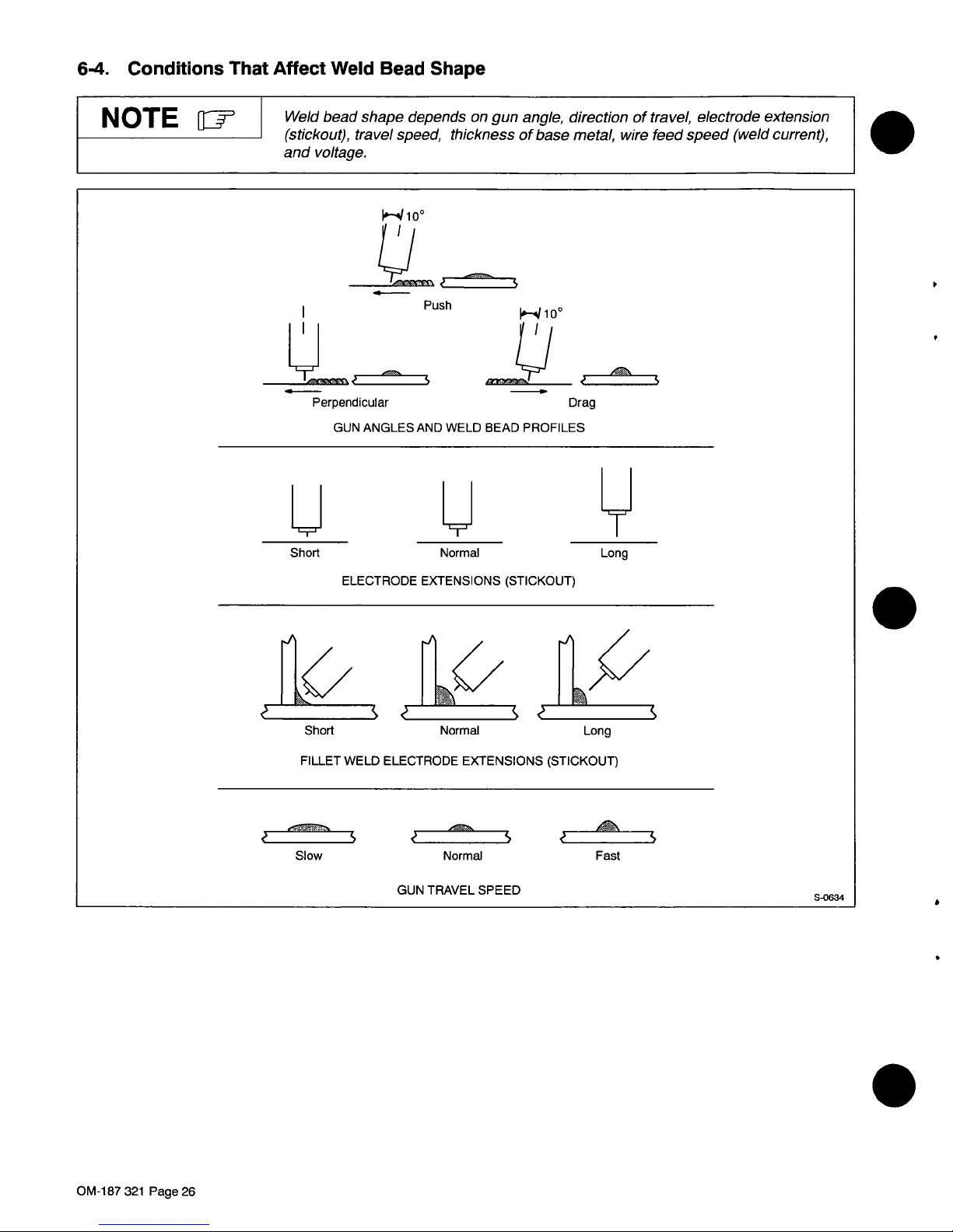
6-4.
Conditions
That
Affect
Weld
Bead
Shape
y
Short
Normal
ELECTRODE
EXTENSIONS
(STICKOUT)
Long
.
N
OTE
~
Weld bead
shape
depends
on
gun
angle,
direction
of
travel,
electrode
extension
(stickout),
travel
speed,
thickness
of
base
metal,
wire
feed
speed
(weld
current),
and
voltage.
Push
I._.~1Oo
Perpendicular
rn~
GUN
ANGLESAND
WELD
BEAD
PROFILES
Drag
Short
Normal
Long
FILLET
WELD
ELECTRODE
EXTENSIONS
(STICKOUT)
Slow
Normal
Fast
GUN
TRAVEL
SPEED
S-0634
OM-187
321
Page
26

6-5.
Gun
Movement
During
Welding
N
OTE
1JIII~
Normally,asingle
stringer
bead
is
satisfactory
for
howevei
for
wide
groove
weld
joints
or
bridging
multiple
stringer
beads
works
better.
most
narrow
groove
weld
joints;
across
gaps,
a
weave
bead
or
1
Stringer
Bead
-
Steady
Movement
Along
Seam
1
2
~
2
Weave
Bead
-
Side
To
Side
Movement
Along
Seam
3
Weave
Patterns
Use
weave
patterns
to
cover
a
wide
area
in
one
pass
of
the
electrode.
S-0054-A
k~4~((((
6-6.
Poor
Weld
Bead
Characteristics
1
1
Large
Spatter
Deposits
2
Rough,
Uneven
Bead
3
Slight
Crater
During
Welding
4
Bad
Overlap
5
Poor
Penetration
S-0053-A
6-7.
Good
Weld
Bead
Characteristics
1
Fine
Spatter
2
Uniform
Bead
.1
3
Moderate
Crater
During
Welding
Weld
a
new
bead
or
layer
for
each
1/Bin
(3.2
mm)
thickness
in
metals
being
welded.
4
No
Overlap
5
Good
Penetration
into
Base
Metal
l~/
5
S-0052-B
4~5
OM-187
321
Page
27

6-8.
Troubleshooting
-
Excessive
Spatter
.
cooltosolid
form
near
weld
bead.
I
.
~
ExcessiveSpatter-scatteringofmoltenmetaJparticlesthat
S-0636
Possible
Causes
Corrective
Actions
Wire
feed
speed
too
high.
Select
lower
wire
feed
speed.
Voltage
too
high.
Select
lower
voltage
range.
Electrode
extension
(stickout)
too
long.
Use
shorter
electrode
extension
(stickout).
Workpiece
dirty.
Remove
all
grease,
oil,
moisture,
rust,
paint,
undercoating,
and
dirt
from
work
surface
before
welding.
Insufficient
shielding
gas
at
welding
arc.
Increase
flow
of
shielding
gas
at
regutator/flowmeter
and/or
prevent
drafts
near
welding
arc.
Dirty
welding
wire.
Use
clean,
dry
welding
wire.
Eliminate
pickup
of
oilorlubricant
on
welding
wire
from
feeder
or
liner.
6-9.
Troubleshooting
-
Porosity
S-0635
Possible
Causes
Corrective
Actions
Insufficient
shielding
gas
at
welding
arc.
Increase
flow
of
shielding
gas
at
regulator/flowmeter
and/or
prevent
drafts
near
welding
arc.
Remove
spatter
from
gun
nozzle.
Check
gas
hoses
for
leaks.
Place
nozzle
1/4to1/2
in
(6-13
mm)
from
workpiece.
Hold
gun
near
beadatend
of
weld
until
molten
metal
solidifies.
Wrong
gas.
Use
welding
grade
shielding
gas;
change
to
different
gas.
Dirty
welding
wire.
Use
clean,
dry
welding
wire.
Eliminate
pick
up
of
oil
or
lubricant
on
welding
wire
from
feeder
or
liner.
Workpiece
dirty.
Remove
all
grease,
oil,
moisture,
rust,
paint,
coatings,
and
dirt
from
work
surface
before
welding.
Use
a
more
highly
deoxidizing
welding
wire
(contact
supplier).
Welding
wire
extends
too
far
out
of
nozzle.
Be
sure
welding
wire
extends
not
more
than
1/2
in
(13
mm)
beyond
nozzle.
Porosity
-
small
cavities
or
holes
resulting
from
gas
pockets
in
weld
metal.
OM-187321
Page28

6-10.
Troubleshooting
-
Excessive
Penetration
I
I
ExcessivePenetration-weldmetalmeltingthroughbasemetal
(
~
)
and
hanging
underneath
weld.
Excessive
Penetration
Good
Penetration
S-0639
Possible
Causes
Corrective
Actions
Excessive
heat
input.
Select
lower
voltage
range
and
reduce
wire
feed
speed.
Increase
travel
speed.
6-11.
Troubleshooting
-
Lack
Of
Penetration
LackOfPenetration
-
shallow
~11~~
fusion
between
weld
metal
and
II
~~1Y
base
metal.
Lack
of
Penetration
Good
Penetration
S-O6~8
Possible
Causes
Corrective
Actions
Improper
joint
preparation.
Material
too
thick.
Joint
preparation
and
design
must
provide
access
to
bottom
of
groove
while
maintaining
proper
welding
wire
extension
and
arc
characteristics.
Improper
weld
technique.
Maintain
normal
gun
angle
of
0to15
degrees
to
achieve
maximum
penetration.
Keep
arc
on
leading
edge
of
weld
puddle.
Be
sure
welding
wire
extends
not
more
than
1/2
in
(13
mm)
beyond
nozzle.
Insufficient
heat
input.
Select
higher
wire
feed
speed
and/or
select
higher
voltage
range.
Reduce
travel
speed.
6-12.
Troubleshooting
-
Incomplete
Fusion
ii
Incomplete
Fusion-failure
of
weld
metal
to
fuse
completely
with
I
base
metal
or
a
preceeding
weld
bead.
L~H
J
S-0637
Possible
Causes
Corrective
Actions
Workpiece
dirty.
Remove
all
grease,
oil,
moisture,
rust,
paint,
undercoating,
and
dirt
from
work
surface
before
welding.
Insufficient
heat
input.
Select
higher
voltage
range
and/or
adjust
wire
feed
speed.
Improper
welding
technique.
Place
stringer
bead
in
proper
location(s)
at
joint
during
welding.
Adjust
work
angle
or
widen
groove
to
access
bottom
during
welding.
Momentarily
hold
arc
on
groove
side
walls
when
using
weaving
technique.
Keep
arc
on
leading
edge
of
weld
puddle.
Use
correct
gun
angle
of
0
to
15
degrees.
OM-187
321
Page
29

6-13.
Troubleshooting
-
Burn-Through
S
S
Burn-Through
-
weld
metal
melting
completely
through
base
metal
resulting
in
holes
where
no
metal
remains.
S-0640
Possible
Causes
Corrective
Actions
Excessive
heat
input.
Select
lower
voltage
range
and
reduce
wire
feed
speed.
Increase
and/or
maintain
steady
travel
speed.
6-14.
Troubleshooting
-
Wa
viness
Of
Bead
Possible
Causes
Corrective
Actions
Welding
wire
extends
too
far
out
of
nozzle.
Be
sure
welding
wire
extends
not
more
than
1/2
in
(13
mm)
beyond
nozzle.
Unsteady
hand.
Support
hand
on
solid
surface
or
use
two
hands.
WavinessOfBead-weld
metal
that
is
not
parallel
and
does
not
cover
joint
formed
by
base
metal.
S-0641
6-15.
Troubleshooting
-
Distortion
Distortion-contractionofweld
metal
during
welding
that
forces
base
metal
to
move.
metal
moves
in
the
direction
of
the
weld
bead.
S-0642
Possible
Causes
Corrective
Actions
Excessive
heat
input.
Use
restraint
(clamp)
to
hold
base
metal
in
position.
Make
tack
welds
along
joint
before
starting
welding
operation.
Select
lower
voltage
range
and/or
reduce
wire
feed
speed.
Increase
travel
speed.
Weld
in
small
segments
and
allow
cooling
between
welds.
OM-187321
Page3O
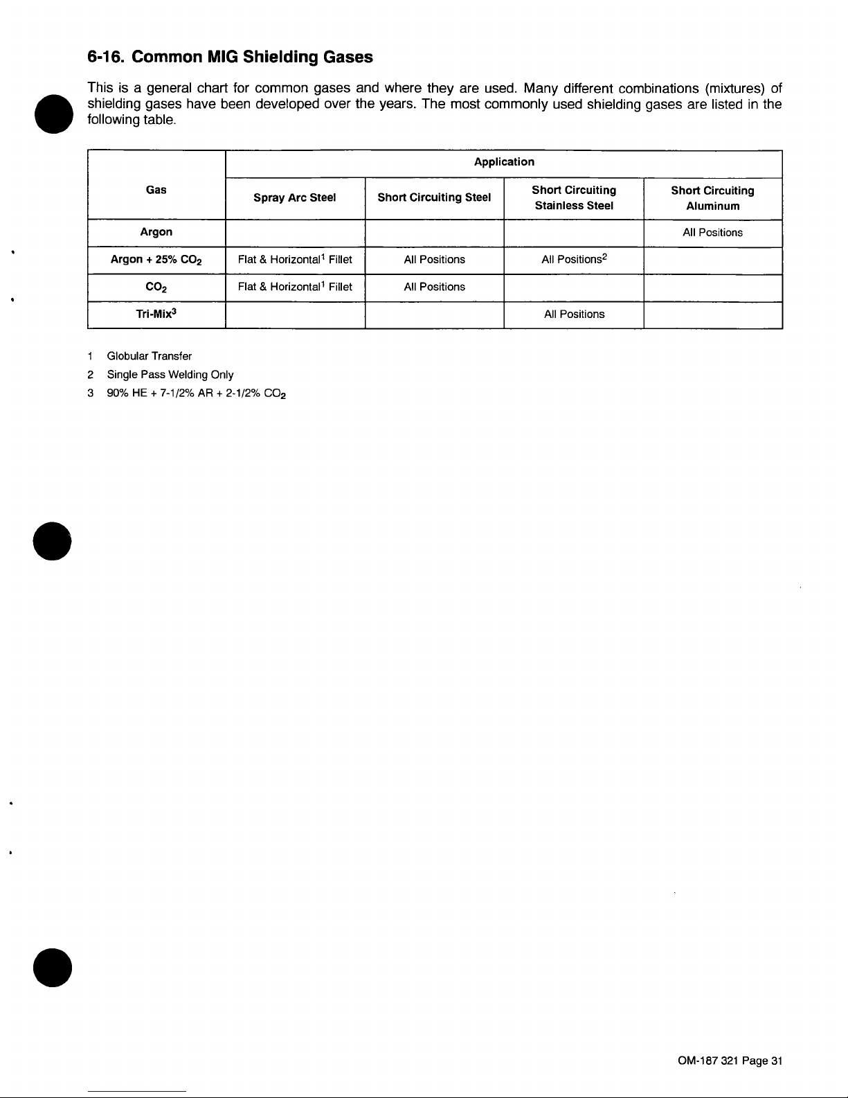
6-16.
Common
MIG
Shielding
Gases
This
is
a
general
chart
for
common
gases
and
where
they
are
used.
Many
different
combinations
(mixtures)
of
shielding
gases
have
been
developed
over
the
years.
The
most
commonly
used
shielding
gases
are
listed
in
the
following
table.
Gas
Application
Spray
Arc
Steel
Short
Circuiting
Steel
Short
Circuiting
Stainless
Steel
Short
Circuiting
Aluminum
Argon
All
Positions
Argon
+
25%
CO2
Flat
&
Horizontal1
Fillet
All
Positions
All
Positions2
CO2
Flat
&
Horizontal
Fillet
All
Positions
Tn-Mix3
All
Positions
1
Globular
Transfer
2
Single
Pass
Welding
Only
3
90%
HE
+
7-1/2%
AR
+
2-1/2%
Co2
OM-187
321
Page
31

SECTION
7-
PARTS
LIST
C
0)
C
.
r~
Figure
7-1.
Main
Assembly
C
ffT
Hardware
is
common
and
not
available
unless
listed.
LU
C
IL
\
~
CO
N
C~
0.1
0).
C~
0)
CO
C~
ST-801
572
OM-187
321
Page
32

Item
Dia.
No.
Mkgs.
Part
No.
S
...~
089899
2
134464
3
+151565
4
Fig7-2
5....
SRi
181012
D1,2...
D3,4...
C1-4...
TP1...
...6
FM....
...8
.9
11
.12
...13....PLG1...
.14...
19...
Z
TP2...
...22
...23
Ti....
...24
...25
S2....
...26....RC2...
...27
Si....
...28
...29
Ri....
...32
F1g7-3
165745
173374
183581
LATCH,
slide
flush
LABEL,
warning
general
precautionary
WRAPPER
CENTER
BAFFLE,
w/components
RECTIFIER
ASSEMBLY,
(consisting
of)
BRACKET
RECTIFIER
DIODE,
rect
15OA300VR
DIODE,
rect
15OA300VS
GROMMET,
SCR
.250
panel
hole
STAND-OFF
CAPACITOR,
cer
disc
.Oiuf
1000VDC
THERMOSTAT,
NCopen2llF
MOTOR,
fan
230V
60/50
Hz
3000RPM
BLADE,
fan
6.000
4wg
30
deg
.175
bore
PANEL,
rear
BEZEL,
front
rear
BRACKET,
bottle
retainer
CHAIN,
weldless
2/0
x
27
NUT,
750-14
knurled
1.68dia
CORD
SET,
250V
6-50P
l2ga
3/c
BUSHING,
strain
relief
VALVE,
24VAC
2
way
BASE
AXLE,
running
gear
WHEEL,
lOin
dia
x
2.25
WASHER,
flat
.812
ID
x
1.469
OD
RING,
rtng
ext
.750
shaft
STABILIZER
THERMOSTAT,
NC
CASTER,
swvl
4.00
in
plastic
TRANSFORMER,
power
main
PANEL,
side
lower
SWITCH,
selector
6
position
RECEPTACLE
W/SOCKETS
SWITCH,
tgl
DPST
40A
600VAC
scr
PANEL,
front
HANDLE,
switch
KNOB,
pointer
POTENTIOMETER
NAMEPLATE,
(order
by
model
and
serial
number)
HANDLE
CLAMP,
work
300A
CABLE,
weld
copper
(orderbyft)
MWG-160
HOUSING
&
PINS
REGULATOR/FLOWMETER,
dual
scale
HOSE,
gas5ft
1
1
2
2
8
2
4
1
1
1
1
2
1
1
1
1
1
1
1
1
2
4
2
1
1
2
1
1
1
1
1
1
1
1
1
111
lOft
1211
+When
ordering
a
component
originally
displaying
a
precautionary
label,
the
label
should
also
be
ordered.
To
maintain
the
factory
original
performance
of
your
equipment,
use
only
Manufacturers
Suggested
Replacement
Parts.
Model
and
serial
number
required
when
ordering
parts
from
your
local
distributor.
OM-187
321
Page
33
Description
Figure
7-1.
Main
Assembly
Quantity
GSi
180
920
037
306
037
305
152
862
026
947
048
420
604
515
123
468
005
656
180
918
190
773
180
923
602
387
605
227
181
072
111
443
125
785
180
916
147
893
186
758
602
250
121
614
180
989
163
266
008
999
180
925
180
924
153
197
048
282
124511
180
917
148
956
097
924
035
897
187
317
147
571
130
750
600
318

gJ~
Hardware
is
common
and
not
available
unless
listed.
221
~21
11
.
2
4
5
6
7
9
Fig.7-4
~12
16
17
18
26
ST-801
631-C
Figure
7-2.
Center
Baffle
w/Components
OM-187
321
Page
34

Item
Dia.
No.
Mkgs.
Part
No.
058427
085
980
605
941
186437
057971
057
745
186435
186436
180915
181
013
178796
180921
180922
158832
083
147
180927
057357
091
685
189486
171
986
134201
183492
180912
097421
097416
072817
Fig7-4..
PLG3....115093..
RC3
...
131059..
Figure
7-2.
Baffle,
Center
w/Components
(Fig
7-1
Item
4)
RING,
retaining
spool
1
NUT,
625-11
.94
hex
1
WASHER,
flat
1
SPRING,
cprsn
.84500
x
.110W
1
WASHER,
fIat
.632
ID
x
1.500
OD
x
.12
1
SPRING,
cprsn
2.430
OD
x
.90
wire
x
2.500
1
HUB,
spool
1
WASHER,
brake
sti
2
BAFFLE,
center
1
CAPACITOR
ASSEMBLY,
(consisting
of)
1
CAPACITOR,
elctlt
20000uf
6
BUSS
BAR,
positive
1
BUSS
BAR,
negative
1
SCREW,
.010-32x.50
hex
hd-slt
S
12
GROMMET,
scr
No.
8/10
panel
hole
8
REEL
SUPPORT
1
BUSHING,
snap-in
nyl
.937
ID
x
1.l25mtg
hole
1
RESISTOR,
WW
fxd
50W
1
CONTACTOR,defprp4oA3P
1
CIRCUIT
CARD
ASSEMBLY,
control
1
STAND-OFF
SUPPORT,
PC
card
4
CIRCUIT
BREAKER,
man
reset
10A250V
1
CIRCUIT
BREAKER,
man
reset
5A
250V
1
TERMINAL,
pwr
output
red
1
TERMINAL,
pwr
output
black
1
RELAY,
end
24VAC
DPDT
20
1
DRIVE
ASSEMBLY,
wire
1
CONNECTOR
&
SOCKETS
1
CONNECTOR&PINS
1
To
maintain
the
factory
original
performance
of
your
equipment,
use
only
Manufacturers
Suggested
Replacement
Parts.
Model
and
serial
number
required
when
ordering
parts
from
your
local
distributor.
Description
Quantity
2
3
4
5
6
7
8
9
10
C6....
11
12
13
14
15
16
R2....
W....
...21....PC1...
...23....CB1...
...24....CB2...
...27....CR1...
OM-1
87
321
Page
35

HANDLE
ASSEMBLY
TUBE,
head
(consisting
of)
....NUT,MlOxl
JACKET,
head
tube
STOP,
nozzle
ADAPTER,
head
tube
nozzle
SPRING,
nozzle
(3
pack)
TIP,
contact
.023
(10
pack)
TIP,
contact
.030
(10
pack)
TIP
contact
.035
(10
pack)
NOZZLE,
slip
type
1/2
orifice
NOZZLE,
slip
type
3/8
orifice
TRIGGER
SWITCH
ASSEMBLY
TERMINAL,
frict
uninsul
fern
22-l8ga
CABLE,
lOft
SLEEVE,
rubber
LINER,
rnonocoil
.023-.035
wire
lOft
(consisting
of)
COLLET,
liner
.035
wire
0-RING,
1/2
IDx.103
CONNECTOR,
gun/feeder
CONNECTOR
&
PINS
CONNECTOR,
circ
clamp
str
rlf
sz
11
Amp
206062-4
II~
Hardware
is
common
and
not
available
unless
listed.
Ref.
ST-lb
832-0
.
Figure
7-3.
Complete
Assembly
(MWG-160
Gun)
OPTIONAL
To
maintain
the
factory
original
performance
of
your
equipment,
use
only
Manufacturers
Suggested
Replacement
Parts.
Model
and
serial
number
required
when
ordering
parts
from
your
local
distributor.
OM-187
321
Page
36
Item
Part
No.
No.
Description
Figure
7-3.
Complete
Assembly
(MWG-160
Gun)
(Fig
7-1
Item
36)
Quantity
.4
.5
.6
.7
11
110793
110795
110780
110779
110781
128878
118
570
112
742
112
750
121
934
112
746
113
017
110794
080565
110792
110797
167440
120715
079 974
110796
079 878
048 834
1
1
1
1
1
1
1
1
1
1
2
1
1
.2
1
14
17
18

Figure
7-4.
Drive
Assembly,
Wire
To
maintain
the
factory
original
performance
of
your
equipment,
use
only
Manufacturers
Suggested
Replacement
Parts.
Model
and
serial
number
required
when
ordering
parts
from
your
local
distributor.
Item
No.
Part
No.
Description
Figure
7-4.
Drive
Assembly,
Wire
(Fig
7-2
Item
29)
Quantity
1
2
180
926
..
180
929
..
MOTOR,
gear
24VDC
HOUSING,
motor
drive
1
1
3
4
5
6
126
838
..
092
237
..
090415..
085
244
.
.
DRIVE
ASSEMBLY,
wire
(consisting
of)
..
KNOB,
adjustment
tension
..
SPRING,cprsn.7200Dx.O72wirexl.250
..
WASHER,
cupped
stl
.328
ID
x
.812
OD
x
.125
lip
1
1
1
1
. .
7
8
9
10
11
.12
085
242
.
.
090416
.
.
124817..
090
443
..
111
622
112
031
.
.
151828..
..
FASTENER,
pinned
..
PIN,
hinge
..
HOUSING,
wire
drive
..
BEARING,
ball
rdl
sgl
row
.315x.866
x
.27
(consisting
of)
SPACER,
bearing
.196
ID
x
.310
OD
x
.500
collar
..
LEVER,
pressure
roll
..
PIN,
cotterhair.054x.750
1
1
1
1
1
1
1
13
14
15
16
.17
124
778
..
174
609
..
090
423
..
058
549
..
010224
..
KNOB,
T
2.000
bar
w/.312-18
st
SCREW,
M6
1.0x20
ROLL,
drive
V
groove
.023-.035
GUIDE,
wire
inlet
1/16
PIN,springCS.187x1.000
1
3
1
1
1
1
2
g~
Hardware
is
common
and
not
available
unless
listed.
16
L
13
15
14
ST-181
053
OM-187
321
Page
37

O
S

This
limited
warranty
supersedes
all
previous
manufacturers
warranties
and
is
exclusive
with
no
other
guarantees
or
warranties
expressed
or
implied.
LIMITED
WARRANTY
-
Subject
to
the
terms
and
conditions
below,
warrants
to
its
original
retail
purchaser
that
new
equipment
sold
after
the
effective
date
otthis
limited
warranty
is
tree
ot
detects
in
material
and
workmanship
at
the
timeitis
shipped
from
factory.
THIS
WARRANTY
IS
EXPRESSLY
IN
LIEU
OF
ALL
OTHER
WARRANTIES,
EXPRESS
OR
IMPLIED,
INCLUDING
THE
WARRANTIES
OF
MERCHANTABILITY
AND
FITNESS.
Within
the
warranty
periods
listed
below,
manufacturer
will
repair
or
replace
any
warranted
parts
or
components
that
fail
due
to
such
defects
in
material
or
workmanship.
Manufacturer
must
be
notified
in
writing
within
thirty
(30)
days
of
such
defect
or
failure,
at
which
time
manufacturer
will
provide
instructions
on
the
warranty
claim
procedures
to
be
followed.
Manufacturer
shall
honor
warranty
claimsonwarranted
equipment
listed
below
in
the
event
of
such
afailure
within
the
warranty
time
periods.
All
warranty
time
periods
start
on
the
date
that
the
equipment
was
deliveredtothe
original
retail
purchaser,
or
one
year
after
the
equipment
is
sent
to
the
distributor.
1.
5
Years
Parts
-
3
Years
Labor
*
Original
main
power
rectifiers
2.
3 Years
Parts
and
Labor
*
Transformer/Rectifier
Power
Sources
*
Plasma
Arc
Cutting
Power
Sources
*
Semi-Automatic
and
Automatic
Wire
Feeders
*
Engine
Driven
Welding
Generators
(NOTE:
Engines
are
warranted
separately
by
the
engine
manufacturer.)
3.
t
YearParts
and
Labor
*
Motor
Driven
Guns
(w/except
ion
of
SpoolmateIB5)
*
Process
Controllers
*
Positioners
and
Controllers
*
Automatic
Motion
Devices
*
Robots
*
Water
Coolant
Systems
*
HF
Units
*
Grids
*
Spot
Welders
*
Load
Banks
*
SDX
Trsnsformers
*
Running
Gear/Trailers
*
Field
Options
(NOTE:
Field
options
are
covered
under
the
limited
warranty
for
the
remaining
warranty
period
of
the
product
they
are
installed
in,
or
foraminimum
of
one
year
whichever
is
greater.)
6
Months
Bafteries
90
Days
Parts
and
Labor
*
MIG
Guns/TIG
Torches
*
Plasma
Culling
Torches
*
Remote
Controls
*
Accessory
Kits
*
Replacement
Parts
*
Spoolmate
t
B5
Limited
Warranty
shall
not
apply
to:
1.
Items
furnished
by
manufacturer,
but
manufactured
by
others,
such
as
engines
or
trade
accessories.
These
items
are
coveredbythe
manufacturers
warranty,
if
any.
2.
Consumable
components;
such
as
contact
tips,
culling
nozzles,
contactora,
relays,
brushes,
slip
rings,
or
parts
that
fail
duetonormal
wear.
3.
Equipment
that
has
been
modified
by
any
party
other
than
manufacturer,
or
equipment
that
has
been
improperly
installed,
improperly
operated
or
misused
based
upon
industry
standards,
or
equipment
which
has
not
had
reasonable
and
necessary
maintenance,
or
equipment
which
has
been
used
for
operation
outside
of
the
specifications
for
fhe
equipment.
MANUFACTURERS
PRODUCTS
ARE
INTENDED
FOR
PURCHASE
AND
USE
BY
COMMERCIAL/INDUSTRIAL
USERS
AND
PERSONS
TRAINED
AND
EXPERIENCED
IN
THE
USE
AND
MAINTENANCE
OF
WELDING
EOUIPMENT.
In
the
event
of
a
warranty
claim
coveredbythis
warranty,
the
exclusive
remedies
shall
be,
at
manufacturers
option:
(t)
repair;
or
(2)
replacement;
or,
where
authorized
in
writing
by
manufacturer
in
appropriate
cases,
(3)
the
reasonable
cost
of
repair
or
replacement
at
an
authorized
service
station;
or
(4)
payment
of
or
credit
for
the
purchase
price
(less
reasonable
depreciation
based
upon
actual
use)
upon
return
of
the
goods
at
customers
risk
and
expense.
manufacturers
optionofrepairorreplacement
will
be
FOB.,
Factory
at
Appleton,
Wisconsin,
or
FOB.
at
an
authorized
service
facility
as
determined
by
manufacturer.
Therefore
no
compensation
or
reimbursement
for
transportation
costs
of
any
kind
willbeallowed.
TO
THE
EXTENT
PERMITTED
BY
LAW,
THE
REMEDIES
PROVIDED
HEREIN
ARE
THE
SOLE
AND
EXCLUSIVE
REMEDIES.
IN
NO
EVENT
SHALL
MANUFACTURER
BE
LIABLE
FOR
DIRECT,
INDIRECT,
SPECIAL,
INCIDENTAL
OR
CONSEOUENTIAL
DAMAGES
(INCLUDING
LOSS OF
PROFIT),
WHETHER
BASED
ON
CONTRACT,
TORT
OR
ANY
OTHER
LEGAL
THEORY
ANY
EXPRESS
WARRANTY
NOT
PROVIDED
HEREIN
AND
ANY
IMPLIED
WARRANTY,
GUARANTY
OR
REPRESENTATION
AS
TO
PERFORMANCE,
AND
ANY
REMEDY
FOR
BREACH
OF
CONTRACT
TORT
OR
ANY
OTHER
LEGAL
THEORY
WHICH,
BUT
FOR
THIS
PROVISION,
MIGHT
ARISE
BY
IMPLICATION,
OPERATION
OF
LAW,
CUSTOM
OF
TRADE
OR
COURSE
OF
DEALING,
INCLUDING
ANY
IMPLIED
WARRANTY
OF
MERCHANTABILITY
OR
FITNESS
FOR
PARTICULAR
PURPOSE,
WITH
RESPECT
TO
ANY
AND
ALL
EOUIPMENT
FURNISHED
BY
MANUFACTURER
IS
EXCLUDED
AND
DISCLAIMED
BY
MANUFACTURER.
Some
states
in
the
U.S.A.
do
notallow
limitationsofhow
long
an
implied
warranty
lasts,
or
the
exclusion
of
incidental,
indirect,
special
or
consequential
damages,
so
the
above
limitation
or
exclusion
may
not
apply
to
you.
This
warranty
provides
specific
legal
rights,
and
other
rights
may
be
available,
but
may
vary
from
state
to
state.
In
Canada,
legislation
in
some
provinces
provides
for
certain
additional
warranties
or
remedies
other
than
as
stated
herein,
andtothe
extent
that
they
may
not
be
waived,
the
limitations
and
exclusions
set
out
above
may
nof
apply.
This
Limited
Warranty
provides
specific
legal
rights,
and
other
rights
may
be
available,
but
may
vary
from
province
to
province.
/
/
A
-
---S
-
-
~
-~
-
p
-
i-;~
Warranty
Elf
ective
January
1,
1008
(Equipment
with
a
serial
number
preface
et
KJ
or
newer)
4-
--
4.
5.
brand_warr
1/98

Owners
Record
Resources
Available
Welding
Supplies
and
Consumables
Options
and
Accessories
Personal
Safety
Equipment
Service
and
Repair
Replacement
Parts
Owners
Manuals
Circuit
Diagrams
Please
complete
and
retaiN
with
your
personal
records.
(
Model
Name
Serial/Style
Number
Purcbase
Dale
(Date
which
equipment
was
delivered
to
original
customer.)
Distributor
Address
City
Stale
Zip
Always
provide
Model
Name
and
Serial/Style
Numher.
Coutact
your
Distributor
for:
CsutacttbeDeliveriggcappjepf,p:
File
a
claim
for
loss
or
damage
during
shipment.
For
assistance
in
filing
or
settling
claims,
contact
your
distributor
and/or
equipment
manufacturers
Transportation
Department.
PRINTED
IN
USA
 Loading...