


Carony Go
Carony Drive
Safety
General
Service and
maintenance
Mechanics
Service manual
(Discontinued)


3
Carony Go/Drive
Safety
General
Service and
maintenance
Mechanics
Electrics
Service manual
1:! Service check-ups
1:2 Instructions for service and
maintenance
1:3 Updates
2:1 Description
2:2 Exploded views and components
2:3 Trouble shooter
2:4 Repair manual
0:! Technical data
3:1 Description / Programming
3:2 Wiring diagrams
3:3 Trouble shooter
3:4 Repair manual

4

5
This chapter covers general safety rules
when servicing the Carony Go/Drive
Safety
!
Use safety glasses, gloves, protective work shoes and other
protective items as required by the work situation.
Batteries contain sulphuric acid which is very corrosive to
the human body and parts of the Carony Go.
Batteries give off Hydrogen gas when charged. This gas is
together with oxygen very explosive.
Begin by disconnect the ground lead when removing a battery. And also connect the ground lead last when fi tting batteries.
Do not connect a discharged battery in series with a
charged one. It can cause the batteries to explode.
Do not wear metal objects like rings and wristwatches. Even
a small voltage can produce high current and can cause
burn injuries.
Always cover the top of the battery with a rag or other nonconducting material when you work close to the batteries.
Batteries always contain substances dangerous to health
and the environment. Discarded batteries must be disposed
of according to local and/or national regulations.

6

7
0:1 Technical data
General
Seat angle 17º
Depth of seat 493 mm
Seat width 408 mm
Height of seat surface in front 510 mm
Backrest inclination -19º till 23º
Backrest height 653 mm
Backrest width 435 mm
Distance of headrest in front of backrest 34 mm
Height of backrest above seat 775 mm
BEV seat specifi cations
Total width, with air tyres 62 cm
Total width, puncture free wheels 60,9 cm
Length 75 cm
Length with anti-tip and foot rests 108 cm
Height without seat 38 cm
Height with seat 115 cm
Total weight 93 kg
Weight of wheel unit with batteries 75 kg
Clearence beneath wheelchair 65 mm
Adjustable seat height 42-55 cm
Dimension front wheels 200x50 mm
Tyre pressure front wheels 2,6 bar
Dimension rear wheels 315x50 mm
Tyre pressure rear wheels 2,8 bar
Range 25 km
Max speed 6,5 km/h
Max reverse speed 3 km/h
Braking distance 0,8 m
Obstacle clearence 6 cm
Turning space180 degrees 150 cm
Hill-climbing ability 6 grader
Max user weight 120 kg
Battery type AGM; 1245
Batteriy max dimension 198x 165x170
Main fuse 50 A
Carony Go/ Drive
Go: Drive:
110-122 cm
33,5 cm
112-126 cm
110 kg
92 kg
65 mm (35 mm)
37-51 cm
Distance from footplate to seat 404-550 mm in 8 steps
Length of footplate 129 mm
Footplate angle variable
Angle of legrest to seat surface 104º
Armrest height 285 mm
Distance to backrest from front edge
of armrest 335 mm
Armrest length 356 mm
Armrest width 57 mm
Armrest angle -38º to 10º
Distance between armrests 438 mm
Carony Go
Carony Drive

8
Carony Go Measurements for TURNOUT applications
INSIDE THE VEHICLE:
Total height with TURNOUT
Measured from vehicle sill + Carony rails and seat:
Carony rails
Turnout + Carony rails + BEV seat
Turnout + Carony rails + Bev-seat
A
B
C
D
E
F
= 950 mm
Measured from where the sill moulding starts to
bend upwards.
= 830 mm
= 630 mm
= 650 mm
Max 375mm (425mm with raising kit)
Measured from ground to vehicle sill.
= 600 mm
0:1 Technical data
840 mm
vehicle sill

9
Carony rails
Turny + Carony rails + Bev-seat
0:1 Technical data
Carony rails
Turny seat raising
spacer 35 mm
B
C
A
A
B
C
D
E
= 1050 mm
This measure depends on the user. A tall person, who is unable to bend the neck, needs
more space. This can, up to a certain point,
be compensated by inclining the backrest a
little bit.
= 1000 mm
Measured by penulating by the approximate
point of Turnys height including the seat.
= 750 mm
Measured by the ultimate out shooting point
of the dashboard.
= 650 mm
Minimum leg space.
Turny 395: max 587 mm
or Turny 300: max 492 mm
E
Carony Go Measurements for TURNY applications

10
0:1 Technical data

11
Service and Maintenance
1:1 Service check-ups
When servicing the Carony Go /Drive, every 6 months
(12 months if rarely used) following chek-ups should be made:
Check:
1. Motor release, see page 12.
2. Rubber housing for lift pillars, see page 12.
3. Control unit arm lock/unlock in the position chosen, see page 12.
4. Front tyres: 2.6 bar, Rear tyres: 2.8 bar
5. Tighten drive motors, see page 12 or method 2:4:1 step 1- 3
Switch the power on and check:
6. Electrical functions
7. Seat adjustment
8. Speed limit when seat raised
9. Battery indicator when charged
10. Reading fault codes
Remove cover and check:
11. Battery contacts, possible oxidation
12. Check battery voltage
13. Check cables and connector.
Every 12 months:
14. Change spring for docking mechanism, see page 13.
15. Adjust release wire for docking mechanism, see page 13.

12
1:2 Instructions for service and maintenance
Tighten drive motors
It is IMPORTANT to tighten all drive motor nuts at every
service situation. If they are not properly tightened the
fastening might be damaged.
See method 2:4:1, pic. 1- 3 for removing the wheel.
Tighten the three nuts on both sides of the wheelchair
as shown in picture.
WARNING!
Do not use too much force! These are aluminium threads and shall not be over tightened.
Rather use some lock fl uid, such as Loctite.
Instructions for the 6 months service
Motor release
If the motor release is not working as it should, see
method 2:4:4 Change of transversal release shaft.
Check if any of the joints or bars are broken.
Control unit arm lock/unlock in the position chosen
If the joystick arm doesent lock in the position chosen, the cause is
most probably a defect gas spring or release lever.
See method 2:4:12 Joystick arm release, change incl. adjustment
and change of gas spring
Rubber housing for seat lift pillars
It is IMPORTANT to check that the rubber housings are not defect.
Defect rubber housings can expose the Ketter-pillars and the seat
height system to water and rust.
See methods 2:4:6, pic. 1- 4, Carony Go
2:4:7, pic. 1- 3, Carony Drive

13
1:2 Instructions for service and maintenance
Change of spring for docking mechanism (Carony Go)
At the 12 month service the spring shall be changed.
Spare part kit: Art. No: 418097 (leaf spring)
See method 2:4:5 Change of docking mechanism (Carony Go)
The wires on both sides shall be adjusted to make the release levers affect the docking mechanism directly.
Adjust release wire for docking mechanism (Carony Go)
Adjust at front.... ...or at the back

14
1:2 Instructions for service and maintenance
Batteries
The Batteries of the wheelchair are of gel type and therefore don’t need any liquid check-up.
Regular charging prolongs the lifetime of the batteries.
When Carony Go is not in use - connect to battery charger!
Charging the batteries
Batteries shall be charged in a ventilated area, using a charger
of type IVO 24/6 IP65.
The charge socket is placed in the front edge of the control box.
Charge socket
!
Cleaning
Cleaning should be done regularly.
Wheels
The wheel pressure needs to be checked regularly. The driving wheels (rear wheels)
shall have a pressure of 2.8 Bar. The front wheels shall have 2.6 Bar.
Low air pressure can cause extra wear and tear to the wheels and drains the battery faster.
Replacing the tube
Place pieces of board under all wheels except the one that shall be amended.
Remove the rear wheel by using a 17 mm wrench.
Remove the front wheel by using a 6 mm hexagon key and a 13 mm wrench.
Let the air out of the tube and remove the tyre from the rim.
Replace the old tube with a new one. Restore and mount the wheel.
Don’t forget to tighten the nut. Infl ate the wheel to specifi ed air pressure.
For upholstery use vacuumcleaner and
upholstery cleaner.
The seat cushion is detachable and can be machine washed in 40 degrees C.
N.B! Do not dry in tumble-drier or drying cupboard!
DO NOT use a high-pressure cleaner and
DO NOT fl ush water on the wheelchair!
This might cause damage to the electricity system etc.
Clean the wheelchair with a moist
towel and a gentle cleaning agent.
Too high air pressure
can cause an explosion!
Tube for rear wheel: Art. No: 418914
Tube for front wheel: Art. No: 420797
Instructions from the user manual

15
Replacing the fuse
The fuse is placed under the plastic cover of the wheel unit.
The cover is Velcro fastened and is easy to pull off.
The main fuse of 50 Ampere is placed on the red cable.
A defective fuse might be caused by a major fault of the electric system.
Replacing the bulbs
Bulbs:
Headlight
Indicators front
Indicators back
Rear light
Socket:
BA 15 s
Ba 15
Ba 15 f
BAY 15 d
Specifi cation:
24V/21W
24V/5W
24V/5W
24V/3W
Replacing headlight bulb:
Remove the lamp body from the control box arm, by unscrewing the two
screws with a size 3 hexagon key.
Unscrew the two screws that fi x the lamp body to its holder.
Unscrew the black socket from the lamp body. Remove the bayonet fastened bulb and replace it with a new.
Remount and tighten all screws.
Replacing bulbs of rear light and rear indicator :
Unscrew and remove the glass from the rear light. Change bulb and
remount the glass.
Replacing bulb of front indicators:
Use a blunt knife or other tool to remove the glass.
Replace the bulb and remount the glass.
1:2 Instructions for service and maintenance
Replacing the batteries
Always replace both batteries at the same time!
Remove the plastic cover, fastened by Velcro. Loosen the wing
nut holding the battery bracket and remove this. Raise the rear
battery upright. Disconnect the cables and remove the battery.
Push the remaining battery as far back as possible, raise it up
and remove it.
When new batteries are connected it is
very important that they are correctly placed.
First connect the minus then the plus poles.
Under the plastic cover of the wheel unit.
battery
battery

16
1:3 Updates
From May 2008 the Control Unit Protection will be updated
From Mrch 2008 there is a new release lever without a lock pin
Control unit protection
A hexagon lock screw is used instead.
Method 2:4:1 step 10: Release the lock screw and lift it up.

17
Mechanics
2:1 Description of mechanical system
Seat lift pillars (Ketter-pillars)
There are two types of pillars:
• Front pillars: Art. No: 417423
• Rear pillars: Art. No: 417424
In case of a defective pillar, replace with a new.
The Carony Go/ Drive is a very compact and low electrical wheel chair.
It has a height adjusting possibility which will provide the driver optimal height for all
opportunities. It is made of steel and powder painted for the rust and impact protection.
The wheels are made of aluminium (drive wheel) and plastic (front wheel), both use
infl atable rubber tyres. See specifi cation for the right pressure.
The height adjustment is mechanically driven by one electrical motor and four Ketterpillars, consisting of an angled gearbox and a screw.
The lift system has a micro switch mounted in one of the Ketter-pillars, this will provide the power module with information about the height, in order to slow down the
wheelchair if the seat is not at its lowest position.
The propulsion system uses two strong 24V electrical motors giving the wheelchair
good performance and good handling. The two motors have both brakes and gear
box included. This is one of the reasons for the compactness, but will still be reliable,
strong and rigid.
Remember when the wheel chair isn’t in use always
put it on charging!
Low and compact
Wheels
Height
adjustment
The motors

18
2:2 Exploded views and components
Carony Go wheel unit
1
15
2
27
14
21
13
3
17
26
25
18
24
11
23
16
5
49
47
22
48
7
4
22
6
28
45
42
46
44
43
31
30
32
39
33
40
12
34
36
20
37
50
38
35
41
19
2:2 Exploded views and components
Component list for Carony Go wheel unit
50 4 Self-cutting screw R6B B6x9.5
49 2 Locking nut M6LM - M5 412215
4
81
814
pma
l ra
eR
2
84
47 1 Bracket rear lamp 001070 418098
46 4 Locking nut M6LM M4 416646
45 4 Screw MC6S M4 x 8 417732
44 2 Direction asher 418185
43 1 Bracket right 418100
42 1 Bracket left 418099
41 2 45 Ah battery 418164
40 2 a-lock Ø6 without cap
073214 h
c
tiwS
1
9
3
38 2 Dummy plug IKPT1713S 418179
37 2 Tapping screw 3.5x13 fzb Berner
87777
418178
36 4 Pop rivet 3,2x6,3 Alu/steel 418182
35 2 Velcro tape rm 418156 2QNN020 ADS Svart
34 2 Velcro tape soft 418155 1QNN020 ADS Svart
33 1 Stop screw SK6SS M4x5 FZB 415597
21081
41
31
1
00
tekcarB4
2
3
31 2 Reex side self-adhering yellow 417868
30 2 Washer BRB 17x30x3 fzb 412959
pot pa
C
1
92
46
7
71475
1100
rae
r
paC
1
8
2
27 2 Column rear 417424
26 4 Plug screw Ø6 L=11,0 417832
25 4 Screw MC6S M4 x 35 417809
24 2 Screw MK6S M6 x 16 414079
23 2 Locking nut M6LM - M6 412305
22 10 Screw MK6S M5 x 10 416744
21 6 Screw MK6S M6 x 12 414079
20 2 Tapping screw 4.2x25 418177 Berner 723851
19 1 Wing nut DIN 315 - M6 417806
18 1 Lifting motor 4028 417427
17 2 Hexagon bar L=369 417426
16 1 Hexagon bar L=434 417425
15 4 Guide bushing 001155 417954
14 1 Power module 417417
13 2 Wheel Ø315 417420
12 1 Motors dynamic 418409 (right) 418410 (left)
11 1 Bracket motor 001074 418011
10 1 Fastening eyes right 001072 418009
9 1 Fastening eyes left 001073 418010
8 1 lock lever battery 418157
7 2 Reex rear round red 418086
6 2 Reex front self-adhering white 417867
3677
1
4 r
ednu
p
a
C
1
5
4 1 Carony Go emblem 418183
3 2 Column front 417423
2 1 Chassis weld assy. 001005 417899
1 4 Rubber bellows 412213
Fig. pcs. Description Art.No:

20
2:2 Exploded views and components
Carony Drive footrest system (DISCONTINUED)
1
2
6
8
22
7
20
4
5
9
3
14
16
15
17
13
16
21
17
18
14
11
12
19
17
15
10

21
2:2 Exploded views and components
Component list for Carony Drive footrest system (DISCONTINUED)
Fig. pcs. Description Art.No:
Konstr Ritad
Kop
va ttasrE
r
ettäsrEalak
S
kdoG
r
tnoK
Artikel nr
Dat
Ritn.nr
Autoadapt AB
jno
JNO
M36
2008-03-31
M36-0034
A
Carony Drive_Right
Carony Drive
Projekt
419195
M36-0001419196Bottom11
411791
Sliderail
22
M36-0017419197Slide_right13
M36-0033419203Upper footrest14
M36-0032419214Footrest1
5
M36-0028419229
Chairplate
1
6
M36 0003419234
Slide rod bracket
17
M36-0021419235
Axel
18
GFM-1214-15419218Glide bushing19
ISO 7380416359Screw M8x40110
ISO 7380
412747
Screw M8x12
411
ISO 7380
411345
Screw M8x16
412
DIN 7991 419239
Screw M6x16
213
DIN 125 - A 6,4412300Washer 6,4x12x1,6814
DIN 125 - A 8,4412332Washer 8,4x16x1,6215
DIN 934 - M6413038Nut M6816
DIN 934 - M8411509Nut M8617
DIN 557 - M8414321Weld Nut
418
SF-DF-3452-Lesjofors
419181
Spring
219
M36-0043419236Sliderod120
ISO 7380 - M6 x 16
410759Screw M6x16
621
419240Starlock222
Anmärkning
Ämne Dim.
BenämningAntalDet-nr.
Exploded view

22
2:2 Exploded views and components
Carony Go foot rest
3
4
2
5
6
7
1
3
4
5
2
6
7
1

23
Ritn.nr
Konstr.
Godk.
Ritad
Kop.
Stand. Skala
Ersätter
Ersatt av
Register nr
Dat.
Kontr.
Autoadapt AB
Ant.
Benämning
Material
Mod-nr Ämne
Dimension
Anm.
Art.Nr.
Det.nr
Exploded view foot rest left
JWA
2005-05-31
000996
A
Carony Go, all
Carony Go
1:2
7 1 Included in fig.6
6 1 Foot / heel support 100630
5 1 Included in fig 2
4 1 Wing screw 412186
3 1 Tube ttings Ackurat 22x19
28-32S
418176
2 1 Footrest left 416562
1 1 Holder foot rest weld assy. 001040 417982
7 1 Included in fig.6
6 1 Foot / heel support 100630
5 1 Included in fig.2
4 1 Wing screw 412186
3 1 Tube ttings Ackurat 22x19
28-32S
418176
2 1 Footrest right 416561
1 1 Holder foot rest weld assy. 001040 417982
2:2 Exploded views and components
Component list for Carony Go footrest left
Component list for Carony Go footrest right
Fig. pcs. Description Art.No:
Fig. pcs. Description Art.No:

24
2:2 Exploded views and components
Carony Go / Drive anti-tip
3
10
7
6
4
11
1
9
5
8
2
12
2
10
6
7
3
4
1
8
9
5
11
12

25
2:2 Exploded views and components
Component list for Carony Go / Drive anti-tip left
Ritn.nr
Konstr.
Godk.
Ritad
Kop.
Stand. Skala
Ersätter
Ersatt av
Register nr
Dat.
Kontr.
Autoadapt AB
Ant.
Benämning
Material
Mod-nr Ämne
Dimension
Anm.
Art.Nr.
Det.nr
Exploded view anti-tip left
JWA
2005-05-30
001000
A
Carony Go, all
Carony Go
1:2
12 2 Screw MK6S M6 x 12 414079
11 1 Spring SF-TF SS1774-04 418180
10 2 Washer 6.4x12x1.6 412300
303414 6O kcol-a29
8 1 Shaft wheel 60 240 414465
103414 8Ø kcol-a27
699714221100 tfahS16
503414 leehW25
599714121100 tlob k
coL14
3 1 Bracket left 001120 417994
2.913 NG046114 eldnaH12
1 1 Anti-tip left weld assy. 001116 417984
12 2 Screw MK6S M6 x 12 414079
11 1 Spring SF-TF-1552-SS1774-04 418180
10 2 Washer 6.4x12x1.6 412300
303414
6Ø kcol-a29
8 1 Shaft wheel 60 240 414465
69
9714221100 tfahS17
103414 8Ø kcol-a26
503414
leehW
2
5
2.913
NG04611
4
el
dn
aH
14
3 1 Locking bolt 001121 417995
2 1 Bracket right 001119 417993
1 1 Anti-tip right weld assy 001115 417983
Component list for Carony Go / Drive anti-tip right
Fig. pcs. Description Art.No:
Fig. pcs. Description Art.No:

26
2:2 Exploded views and components
Carony Go / Drive lever system
1
2
4
9
7
5
6
8
10
11
3

27
2:2 Exploded views and components
Component list for Carony Go / Drive lever system
Fig. pcs. Description Art.No:
838014 pac tuN411
10 2 Shims 12x18x0.5 415716
9 1 Screw MK6S M6 x 12 414079
8 1 Washer 7x35x2 SRKB fzb 417804
7 2 Locing nut M6LM - M12 412984
6 2 Locking nut M6LM - M8 413232
5 2 Screw MC6S M8 x 80 416585
4 2 Front wheel Ø175 412193
3 2 Alu front forks 151mm MBL 418084
2 2 Slide bearing COB010F/FS-1F 2515 418163
1 1 Lever arm weld assy. 001032 417985

28
2:2 Exploded views and components
Carony Go / Drive joystick arm system
A-A ( 1 : 2 )
B ( 0,30 : 1 )
A
A
B
6
11
22
8
12
13
3
23
7
24
20
27
21
2
1
9
10
25
28
31
32
33
34
29
30
18
15
16
14
5
17
4
19
26

29
2:2 Exploded views and components
Component list for Carony Go / Drive joystick arm system
Fig. pcs. Description Art.No:
34 1 Conduit entry Berner 6x9.5x1.6 418172
33 1 Cable chain E04.07.015.0 418134
32 1 Washer 8.4x16x1.6 412332
31 1 Screw MK6S M8 x 12 svartkrom 412348
30 2 Screw MC6S - M5 x 20 412311
29 2 Screw MF6S M5 x 16 410761
28 2 Washer Ø8x14x1 Unlico 418170 Det.nr 1006710000VR
27 1 Draw spring Berner 418171 Art.Nr. 30437.9
26 1 Screw MK6S M5x6 412360
25 1 Screw MF6S M5 x 10 416726
24 1 Slide bearing Ø12 Ulinco 418169 Det.nr. 31-36624
23 1 Slide bearing Ø8 Ulinco 418168 Det.nr. 31-1092270000
22 3 Plug screw Ø5 L=9.6 416007
29971
4130100
t
fahS
1
12
16771482010
0
thgi
r
pa
C
102
19 1 Latch right 001030 417970
18 1 Protection device 001200 417990
17 1 Joystick Shark 417416
16 1 Spacer latch 001273 417991
15 2 Screw MC6S M4 x 10 417731
14 1 Hinged bracket right 417972
13 1 Slide bearing COB010/FS-1 1412 418161
12 1 Slide bearing COB010F/FS-1F1417 418160
103
414
8Ø kco
l
-a
411
10 2 Screw MF6S M5 x 8 410142
98
971
4
01
6
000
t
f
ahS
1
9
889714
90600
0
t
fahS
2
8
869714
717000
thgir raB17
6 1 Protective device weld assy. 001024 417966
5 1 Bracket right weld assy. 001021 417962
4 1 Arm right weld assy. 000589 417964
3 1 Bracket arm right weld assy. 000581 417960
2 1 Gas-Spring Eurimex 418154 10-28-30-173-3000N
1 1 Release-Mechanics 418153 LA-SOHE67-KU
* pos. 6 Protective device weld assy. New from 2008-05: Art. No: XXXXXX
(*)

30
2:2 Exploded views and components
Carony Go / Drive motor release handle left
18
12
11
19
5
14
10
4
13
9
7
6
8
21
22
24
25
23
22
3
26
20
15
16
2
17
1

31
2:2 Exploded views and components
Component list for Carony Go / Drive motor release handle left
Fig. pcs. Description Art.No:
26 1 Screw MC6S M6x25 412904
25 2 Screw MC6S M6 x 10 414971
24 6 Nut M6M M5 413084
23 4 Plug screw 416007
22 2 Locking nut M6LM M6 412305
21 6 locking nut M6LM M5 412215
20 2 Tension pin FRP 3x12 412585
19 1 Screw MC6S M5 x 16 417736
095214 ssoB181
17 2 Retaining ring DIN 6799 - 8 418158
16 2 Slide bearing Iglidur clip-2
MYM-10-10
418142
1418
1
49531
00 kco
l25
1
14 1 Tension pin FRP 3 x 20 412585
13 1 Screw MC6S M6x45 414237
12 1 Release knop 001049 417978
2
59
71
4
8
40100
tekca
rB
11
1
10 1 Adjusting lever left 001047 417976
9 1 Bracket left 001046 417974
8 2 Thread rod M5 L=35 M4171
7 1 Thread rod M5 L=110 M4170
6 6 Toggle joint A8 Kontima M5 418175
5 1 Spring SF TFK 3190 418174
4 1 Washer 6,4x18x2 418173
3 1 Screw MK6S M6x16 410759
2 1 Shaft weld assy. 001354 417998
1 2 Bracket weld ass
y
. 001042 417986

32
2:2 Exploded views and components
Carony Go rails
5
7
4
3
9
10
8
11
12
1
2
6
13
9
11
2
8
10
12
4
1
7
3
6
5
13

33
Component list for Carony Go rail left
Fig. pcs. Description Art.No:
Ritn.nr
Konstr.
Godk.
Ritad
Kop.
Stand. Skala
Ersätter
Ersatt av
Register nr
Dat.
Kontr.
Autoadapt AB
Ant.
Benämning
Material
Mod-nr Ämne
Dimension
Anm.
Art.Nr.
Det.nr
Exploded view slide bar left
JWA
2005-06-01
001003
A
Carony Go, all
Carony Go
0,46:1
13 1 Washer BRB 6,4x12x1,6 FZB 412300
12 1 Plate spring 001261 418097
11 2 Screw MF6S M6x20 417042
10 1 Tension pin FRP 3x12 412585
30
0814760100
tfahS19
359714850100 pac kcoL18
718714960100 eriW17
303414 6Ø kcol-a16
525614 bon
K15
491214701 06
gnisuoH14
3 2 Slide bearing COB010F/FS-1F 0608 418162
2 1 Release handle left weld assy. 001297 418001
1 1 Slide bar left weld assy. 001053 417981
Ant.
Benämning
Material
Mod-nr Ämne
Dimension
Anm.
Art.Nr.
Det.nr
13 1 Washer BRB 6,4x12x1,6 FZB 412300
12 1 Spring plate 001261 418097
11 2 Screw MF6S M6 x 20 417042
10 1 Tension pin FRP 3 x 12 412585
30
081476010
0
tfahS
1
9
35
9714
850100
pac
kcoL
18
303414 6O kcol-a17
49121
4701 0
6 gnisuoH1
6
525614
bonK15
718714 eriW
14
3 2 Slide bearing COB010F/FS-1F 0608 418162
2 1 Slide bar right weld assy 000597 417980
1 1 Release handle right weld assy 001296 418002
Fig. pcs. Description Art.No:
Component list for Carony Go rail right
2:2 Exploded views and components

34
2:2 Exploded views and components
Carony Go / Drive seat and armrests
1
8
7
6
3
5
2
10
9
4

35
Component list for Carony Go / Drive seat and armrests
Fig. pcs. Description Art.No:
2:2 Exploded views and components
Ant.
Benämning
Material
Mod-nr Ämne
Dimension
Anm.
Art.Nr.
Det.nr
10 1 Arm rest left. Inkl. screw and
washer
417847
9 1 Arm rest right. Inkl. screw and
washer
417846
8 2 Washer BRB 6.4x16x1.5 FZB 415511
7 2 Screw MK6S M6 x 12 414079
6 4 Screw MK6S M10 x 50 412226
700814451100 recapS
25
4 2 Bracket weld assy. 001294 418006
500814251100 tekcarB
2
3
40
0814351100
r
eca
pS
22
024001
riahC1
1

36
2:3 Trouble shooter
Trouble shooting on Mechanics
Height adjustment does not function, but the lift motor is running.
Height adjustment is lifting unevenly.
Drive motor is running but the the
wheelchair is not moving.
Wheelchair is making turns to the
left or to the right when joystick is
moved forward or backwards.
Carony Drive footrest is not moving forward when the seat is
lowered.
The seat is unstable and wobbly.
The joystick arn can not be folded
up or down.
The joystick arm is loose.
The brake is not functioning
Carony feels slow and unstable.
Motor can not be released.
Check lift motor or all Ketter-pillars.
Check lift motor or Ketter-pillars
Adjustment or change of linkage
for the motor release.
Check transversal release shaft or
motor/transmission.
Linkage for Carony Drive footrest
system is loose or needs adjusting.
Ketter-pillar bushings are worn out.
Adjust lock lever for the gas spring
or replace it.
Change the arm attachment.
Change brakes or motors
Check tyre pressure
Check release linkage.
SYMPTOM MEASURE METHOD
Lift motor: 2:4:10 or11
Pillars: 2:4: 6 to 9
Lift motor: 2:4:10 or11
Pillars: 2:4: 6 to 9
Motor release: 2:4:4
Transversal release shaft:
2:4:4
or
Motor change 2:4:1 or 2
See Exploded view of Carony
Drive footrest system. Adjust
and tighten the linkage.
Bushing: 2:4:16
Joystick arm release:
2:4:12
Spare part “Arm attachment”:
Right side # 417960
Left side # 417961
Change brake plates:
2:4:3
or Change motors:
2:4:1 or 2
Front wheels: 2.6 bar
Rear wheels: 2.8 bar
Transversal release shaft:
2:4:4

37
2:4 Repair manual
2:4:1 Right side drive motor, replace and service
2:4:2 Left side drive motor, replace and service
2:4:3 Brakes, replace
2:4:4 Transversal release shaft, replace
2:4:5 Docking mechanism Carony Go, replace
2:4:6 Rear Ketter-pillar of Carony Go, replace
2:4:7 Rear Ketter-pillar of Carony Drive, replace
2:4:8 Front Ketter-pillar of Carony Go, replace
2:4:9 Front Ketter-pillar of Carony Drive, replace
2:4:10 Lift motor Carony Go, replace
2:4:11 Lift motor Carony Drive, replace
2:4:12 Joystick arm release, replace
incl. adjustment and change of gas spring
2:4:13 Docking mechanism wire, replace
2:4:14 Anti-tip, replace
2:4:15 Footrest rails for Carony Drive, replace
2:4:16 Ketter-pillar bushings, replace

38
2
2:4 Repair manual
2:4:1 Replace and service the right side drive motor
RIGHT MOTOR
1. Place a distance under the chassis. 2. Set the motor release lever in drive position.
Remove the hub cap.
3. Remove the wheel nut by using a 17 mm
socket wrench.
4. Remove the wheel. Fix the wedge to the motor
axle with a tape.
5. Release the pin lock from the ball joint of the
motor release mechanism.
6. Loosen the ball joint.

39
2:4 Repair manual
2
RIGHT MOTOR
7. Remove the power module according to 3:4:2
Remove the batteries: User manual
8. Unscrew the three screws that fi x the motor by
using a 4 mm hexagon key.
9. Lift out the motor. 10. If the motor needs to be replaced push out
the small pin of the release lever and dismount
the spring and the lever.
11. If the brushes need to be replaced you can keep the release lever mounted.
Unscrew the brushes and replace them with new.

40
2:4 Repair manual
LEFT MOTOR
2
2:4:2 Replace and service left side drive motor
Follow the instruction acording to 2:4:1 Replacing
and servicing the motor on the right side
Fig. 1- 7/8.
Remove the batteries according to the User Manual.
7. Remove the screw that fi xes the motor release
lever and remove the lever.
8. Cut the bundle band holding the cable.
9. Unscrew the three hexagon screws for the
motor

41
2
LEFT MOTOR
2:4 Repair manual
10. Lift out the motor and disconnect the contact for the power module. The motor might be diffi cult
to remove, it has to be lifted as high up as possible to allow the support towards the bottom of the
compartment to run free.
11. If the motor needs to be replaced, pusch out
the small pin for the release lever and dismount
lever and spring from the old motor.
12. If the coal cinders need to be replaced the
lever can remain mounted. Dismount the brushes
from te holders and replace them with new.
13. Remount the motor in reversed order.
NOTE! Run the cable through the slit and do
not forget to fi x it to the bottom with a bundle
band.

42
2:4 Repair manual
BRAKE
2
2:4:3 Replace motor brake plate
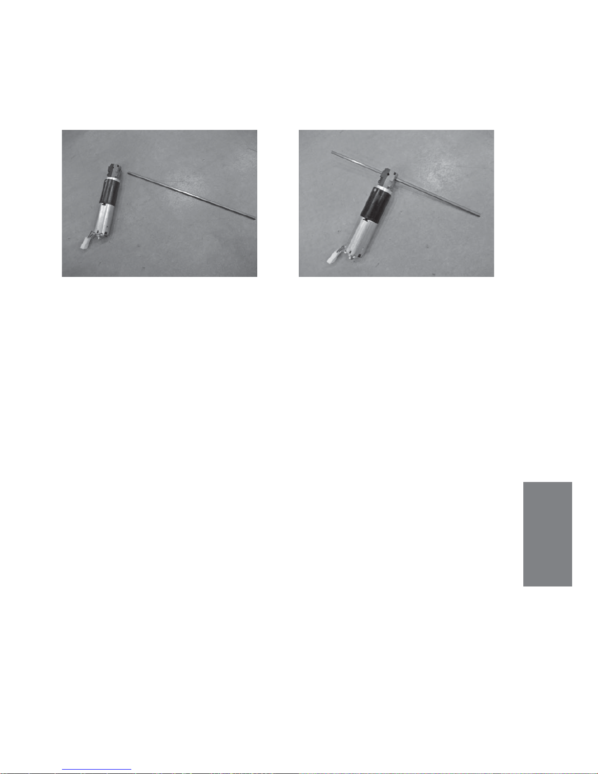
1. Dismount the motor according to instructions
2:4:1 and 2:4:2.
Unscrew the two screws of the motor cover and
remove the cover.
2. Unscrew the hexagon screws holding the
thrust plate. Remove the thrust plate.
Use a solder pen to heat them before trying to
loosen them, it will save the Loctite.
3. Remove the friction lining, clean it (wipe it off)
or replace it with a new if required.
4. Remount the thrust plate. This can only be
mounted in one way.
Mount the motor cover and the motor according
to instructions 2:4:1 and 2:4:2.

43
2
TRANSVERSAL RELEASE SHAFT
2:4 Repair manual
2:4:4 Replace transversal release shaft
1. Dismount the ball joint on both sides. (instruc-
tions 2.4.1 fi g. 5 and 6)
2. Unscrew the two M4 screws that fi x the clip
bearings.
3. Lift out the transversal release shaft. 4. The clip bearings may now ne replaced.
5. Mount the new in reversed order.
Adjust the linkage so that both wheels
are released at the same time.

44
2:4 Repair manual
DOCKING MECHANISM
2
2:4:5 Replace docking mechanism (Carony Go)
1. Remove the seat. Take away the plug from the
wire hole by using a fl at tool.
2. Unhook the wire from the hole.
4. Dismount the plate spring behind the docking
mechanism.
3.
5. Locate the pin that holds the axle for the cup. 6. Knock away the pin by using a 3 mm drift.

45
2
DOCKING MECHANISM
2:4 Repair manual
7. The tension pin.
9. Remount in reversed order and make sure to
use a new pin.
8. Press out the axle for the cup.
The spring shall be changed every 12 months !

46
2:4 Repair manual
REAR KETTER PILLARS CARONY GO
2
2:4:6 Replace REAR Ketter-pillars of Carony Go
3. Place the wheel unit on the side and remove
the bottom cover.
1. Remove the seat and pull away the top cover.
Unscrew the 4 hexagon screws of the Carony
rails.
2. Put the rails aside and loosen the cable chain.
4. Cut away the bundel bands from both of of
the Ketter-pillar rubber housings.
5. Unscrew the two screws holding the Ketter-pillars.
6. Unscrew the two screws of the lift motor attachment.
• Rear pillars: Art. No: 417424

47
2
REAR KETTER PILLARS CARONY GO
2:4 Repair manual
7. Pull the pillars slightly outwards unil the hexa-
gon rod can go free. Cut away the locking clips
from the hexagon rod. Pull away the hexagon
rods, one at a time, to allow removal of the damaged pillar. Replace the damaged pillar with a
new.
8. Make sure to get the upper part of the new
Ketter-pillar facing towards the correct position,
to fi t the Carony rail when remounting.
Do not forget to place an o-ring to lock
the hexagon rod!
9. Be extremely careful to get the same height
of the new Ketter-pillar, - shall not differ more than
1 mm compared to the others.
Uneven pillar heights causes damage.
Make sure to measure from the pipe (not
from the bushing, which might be differently
mounted).

48
2:4 Repair manual
REAR KETTER-PILLAR OF CARONY DRIVE
2
2:4:7 Replace REAR Ketter-pillar of Carony Drive
1. Remove the seat by unscrewing the 4 screws.
Take away the top cover. Unscrew the one screw
holding the joystick arm and put it aside. Loosen
the cable chain.
2. Remove the nut from the balljoint attachment
for the footrest system.
3. Unscrew the entire Carony Drive unit from the
Ketter-pillars (4 screws).
4. Dismount the batteries, according to method
3:4:1. Remove plastic cover by pulling the bottom edge. Disconnect possible rear light cables.
5. Place the Carony on one side and remove the
botton cover.
6. Unscrew the screws holding the DroveLOC
plate.
• Rear pillars: Art. No: 417424

49
2:4 Repair manual
2
7. Unscrew also the two front screws for the
DriveLOC plate.
8. Cut away the bundle band and remove the
rubber housing from the Ketter-pillar that is going
to be changed.
9. Unscrew the two screws of the lift motor at-
tachment.
10. Pull the pillars slightly outwards unil the hexagon rod can go free. Cut away the locking of
the hexagon rod. Pull away the hexagon rods,
one at a time, to allow removal of the damaged
pillar. Replace the damaged pillar with a new.
11. Make sure to get the upper part of the new
Ketter-pillar facing towards the correct position,
to fi t the Carony rail when remounting.
Do not forget to place an o-ring to lock
the hexagon rod!
12. Be extremely careful to get the same height
of the new Ketter-pillar, - shall not differ more than
1 mm compared to the others.
Uneven pillar heights causes damage.
Make sure to measure from the pipe (not from
the bushing, which might be differently mounted).
REAR KETTER PILLAR CARONY DRIVE

50
2:4 Repair manual
FRONT KETTER-PILLAR OF CARONY GO
2
2:4:8 Replace FRONT Ketter-pillar of Carony Go
3. Place the wheel unit on the side and remove
the bottom cover.
1. Remove the seat and pull away the top cover.
Unscrew the 4 hexagon screws of the Carony
rails.
2. Put the rails aside and loosen the cable chain.
5. Unscrew the two screws holding the Ketter-pillars.
10. Pull the pillars slightly outwards unil the hexagon rod can go free. Cut away the locking of
the hexagon rod. Pull away the hexagon rods,
one at a time, to allow removal of the damaged
pillar. Replace the damaged pillar with a new.
4. Cut away bundle band from rubber housing
of the the Ketter-pillar that shall be changed.
• Front pillars: Art. No: 417423
51
2:4 Repair manual
2
FRONT KETTER PILLARS CARONY DRIVE
2:4:9 Change of FRONT Ketter-pillar of Carony Drive
12. Be extremely careful to get the same height
of the new Ketter-pillar, - shall not differ more than
1 mm compared to the others.
Uneven pillar heights causes damage.
Make sure to measure from the pipe (not from
the bushing, which might be differently mounted).
Follow the instructions of method 2:4:7 Change of REAR ketter-pillar of Carony Drive
Use the instructions from 1 - 3
Do NOT remove rear cover or disconnect batteries, pic. 4
Pic. 5: Just remove the plastic cover (NOT the DriveLoc plate)
Proceed from pic. 8 through to pic. 12.
11. Make sure to get the upper part of the new
Ketter-pillar facing towards the correct position,
to fi t the Carony rail when remounting.
Do not forget to place an o-ring to lock
the hexagon rod!
• Front pillars: Art. No: 417423

52
2:4 Repair manual
LIFT MOTOR CARONY GO
2
2:4:10 Replace lift motor on Carony Go
3. Place the wheel unit on the side and remove
the bottom cover.
1. Remove the seat and pull away the top cover.
Unscrew the 4 hexagon screws of the Carony
rails.
2. Put the rails aside and loosen the cable chain.
4. Unscrew the two screws holding the Ketter-pillars.
5. Unscrew the two screws of the lift motor attachment.
6. Pull the pillars slightly outwards unil the
hexagon rod can go free. Cut away the locking
of the hexagon rod. Pull away the hexagon rod,
enough to remove the lift motor.
53
2:4 Repair manual
2
LIFT MOTOR OF CARONY GO
7. Mount the new lift motor.
Do not forget to place an o-ring to lock
the hexagon rod!
2:4:11 Replace lift motor of Carony Drive
Follow the instructions according to 2:4:7 Change of REAR Ketter-pillar of Carony Drive
Use the instructions from 1 - 9
Then follow the instructions from pic. 6 through to 8, according to 2: 4:10 Change of Lift
motor on Carony Go

54
2
2:4 Repair manual
2:4:12 Replace Joystick arm release lever
incl. adjustment and change of gas spring
1. Remove the plastic cover under the joystick
arm, by fi rst unscrewing the Phillips screw and
then the three plastic clips.
2. Disconnect the cable from the joystick.
3. Remove the release head by fi rst removing
the ball of the release lever.
4. Unscrew the locking screw that is placed underneath the joystick. The dismounting will
be easier if you fi rst compress the gas spring 5-10 mm, fold the arm slightly and lock it.
5. Place the arm with the inner side facing up.
To be able to remove the A-lock washer from the pin it is easier if you fi rst use a centre punch
and a hammer. Now you can dismount the gas spring.
JOYSTICK ARM RELEASE LEVER

55
2
JOYSTICK ARM RELEASE LEVER
2:4 Repair manual
6. Remove the counter nut and unscrew the
release head from the gas spring.
Screw the new release head onto the gas spring
until the head of the pin is in contact with the
contact plate. Then screw the gas spring 1 and
3/4 turns further.
Direct the gas spring in line with the release head
and lock it with the counter nut.
Now the gas spring is ready to be remounted.
REMOUNTING:
7. Place the completed gas spring in the right
position and fi x it with a pin.
Place the arm so that the pin holds on to the side
where the A-lock is, then beat in a second pin.
8. Compress the gas spring 5-10 mm. Mount the
arm onto the arm attachment. Fix it with the locking screw.
9. Remount the cover.

56
2
2:4 Repair manual
2:4:13 Replace docking mechanism wire.
1. Use a pair of slim fl at pliers and release the
end of the wire from the lock head.
2. Remove the outer nut of the wire adjustment
from the rail.
3. Remove the outer nut also from the front wire
adjustment.
4. Twist out the z-formed end piece from the arm.
5. Mount a new wire in the reversed order.
Note how the wire runs by the rear pillar.
6. Adjust until there is no play.
DOCKING MECHANISM

57
2
ANTI-TIP
2:4 Repair manual
2:4:14 Anti-tip
1. Knock away the A-lock washer on one side and pull out the pin.
2. Protect the handle with a piece of cloth.
Remove the handle by unscrewing it, using a
pair of universal pliers.
3. Remove the lock head and the spring.
Clean and grease the spring and the lock head.
4. Remount in reversed order.

58
2
2:4 Repair manual
FOOTREST RAILS
2:4:15 Replace footrest rails for Carony Drive
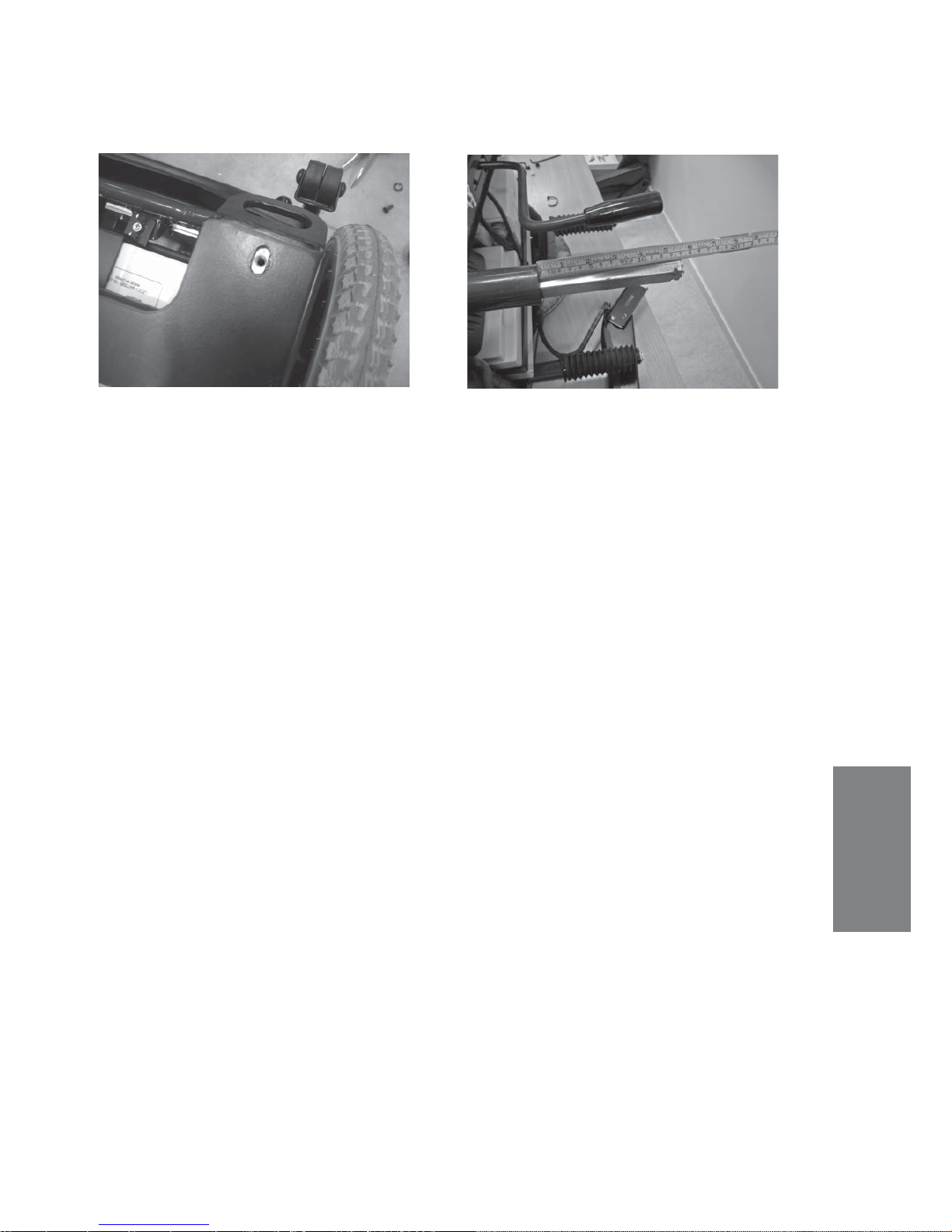
1. Unscrew the 4 screws of seat from underneath. Adjust the height of the unit until the rear
rail screws are reachable.
2. Start by unscrewing the rear screw of the rail
that needs changing.
3.
4. Adjust the height to be able to unscrew also
the front screw.
5. Locate the bolts from underneath and unscrew
them. The bolts have loose welded nuts inside the
rail, so there is no need for a key.
6. Now you can press the rail backwards to
remove it.

59
2
2:4 Repair manual
FOOTREST RAILS
7. This is what has been removed.
8. When remounting, place the weded nuts
inside the rail when the rail is in position.
Screw in reversed order.
Check the function!

60
2
2:4 Repair manual
KETTER PILLAR BUSHINGS
2:4:16 Replace Ketter-pillar bushings
1. Remove the seat:
Carony Go: release the seat and remove it.... ...Carony Drive: unscrew the 4 screws from
underneath and remove the seat.
2. Carony Drive: Remove the fottrest system unit
from the Ketter-pillars by dismounting the link
and unscrewing the 4 srews.
Carony Go: remove the Carony rails.
3. BE CAREFUL with the cable chain from the
joystick arm, it can easily be damaged.
4. Cut away the bundle band that fi xes the rubber housing and remove this.
5. Drill out the pop rivet.

61
2
2:4 Repair manual
KETTER PILLAR BUSHINGS
6. Carefully remove the bushing by using a tool.
7. Tap down the new bushing in level with
the pipe, by using a plastic hammer.
8. Drill a new hole in the bushing and mount a
new pop rivet.

62
2

63
Electrics
3:1 Description and programming
of the electrical system
Control unit Shark dk-remd21 (boost + 2 seats + lights)
1
2
Decrease speed
Speedometer
Hazard lights
Left indicator
Right indicator
Battery gauge
ON/off
1 Seat height adjustement
2 not in use
Headlights/rear lights
Service indicator (fl ash code)
Horn
Increase speed
ON/OFF button When pressed all battery gauge indicators will light briefl y. Holding
it down for four seconds the Carony Go will enter lock mode (to turn the Carony Go
on again press the horn button twice).
DRIVING SPEED. To increase speed press Hare for decrease press Turtle. The speed is
set to 20% intervall but can be changed for more precise speed. Press both hare and
turtle buttons at the same time, than you can adjust the speed in small units by holding
the respectively buttons for 1 s.
BATTERY GAUGE All green LED indicate well charged batterys
Amber and red indicates moderately charged batterys
Red indicates almost empty batteries.
ALWAYS CHARGE THE CARONY GO WHEN YOU ARE NOT USING IT !

64
3:1 Description and programming
Display Description This means... Notes
All LED is off
All LED is on steady
Left RED LED is fl ashing
Right to left “chase”
Left to right “chase”
alterning with steady
display
All LED is fl ashing
2 fl ashing Amber LEDs
Power is off
Power is on
Battery charge is low
SHARK is being brought out
of lock mode
SHARK is in programming,
inhibit and/or charging
mode
SHARK has detected an
Out Of neutral At Power Up
(OONAPU) condition
A comunication fault exists
between the power module
and the remote.
Charge batteries as soon
as possible.
To unlock SHARJK press the
horn button twice within
10 s.
The steady LED indicate
the current state of battery
charge
Release the joystick back to
neutral.
Check the power module
for a fault, the cable for
damage, and that the battery is suffi ciently charged.
SEAT FUNCTION The Carony go uses only seat function number one. Pressing this
button means that you can move the seat up and down. Avoid end positions to prevent overload for the lift motor.
1
2
HEAD LIGHTS (Option) If the Carony Go is equipped with lightnings this is the button
to turn the front and rear lights on. Pressing the button again will turn the lights off.
(Optional) INDICATORS To indicate left or right turns. Pressing the button again will
make it stop. The Carony Go is equipped with a auto cancel for the indicators wich
means that after 10 s the indicators will go off.
(Optional) HAZARD LIGHTS When a malfunction occurs you can press the hazard
wich will turn the both left- and right indicators on.
ATTENDANT CONTROL LED, indicating when the Attendant Remote Control is
switched on. (User mode is off).
SERVICE INDICATOR LIGHT Referring to the Flash Codes. For a list of the Flash Codes
and what faults they indicate, reference
65
3:1 Description and programming
Locking and unlocking the control unit
The lock function of the control unit is disabled (off) as supplied from the factory.
However the programmable feature can be enabled and used to prevent unauthorized people from turning it on.
To lock the control unit
While power is ON, press and hold the power button for
4 seconds.
The display will turn off immediately.
After 4 seconds all LED’s will fl ash briefl y and the horn will
sound a sharp beep.
The power will then turn off.
When the control unit is locked, press the power button to
turn it on.
All LED’s will fl ash briefl y. The Battery Gauge LED*s will
then perform a slow right-to-left chase.
Press the Horn button 2 times before the countdown is
completed (approximately 10 seconds).
The current state-of-charge will then be displayed and the
control unit may be operated normally.
To unlock the control unit

66
3:1 Description and programming
3
3
CHARGING The charge socket is underneath the control unit. The Carony Go
will be charged both if the unit is on or off.
ALWAYS CHARGE THE CARONY GO WHEN NOT USING IT!
Power module DK-PMB-21 (boost + 2 seats + lights)
The power module has a capacity of 60 amp.
For the Carony Go only 35 amps is used to save power.
There is a boost function that gives extra 15 amps for maximum 10 s. when needed.
Electrical specifi cations:
Minimal Nominal Max Units
Carony Go operating voltage 18 24 27 V
Carony Go Current 0 0-35 35 A
Boost Current 0 0-15 15 A
Boost Current time 0 0-10 10 s
Idle Current - 120 - mA
Seat Current 0 6 12 A
Light feeding - 24 - V
Drive motor 0 0-230 230 W
Drive motor cont. current - 8 - A
Drive motor resistance - 250mOhm - Ohm
Short Circuit Current Control* 8 - 15 mA
* Because there is only one main fuse (50 A) the Carony Go is equipped
with a short circuit control system that inhibit current fl ow through circuits if
short circuited.
Charging
• When chargeing, charge will continue also if the control is turned OFF
• Use the Battery Charger indication to show if the battery is fully charged or not,
even if the control panel should indicate otherwise.

67
Communication between power module and control unit
SHARK BUS The power module communicates with the Control Unit through the SHARK BUS. There
are four cables, two primarily and two as back up.
Attendance drive
ATTENDANCE DRIVE (Option) The attendance drive makes it possible for the care giver to operate the Carony Go. You can switch between user mode and attendant mode. The speed potentiometer adjust the overall speed/response of the chair. Adjust it depending on the speed you
want to travel in (depending on the walking speed of the care giver).
3:1 Description and programming

68
3:1 Description and programming
Programming the control system
WARNING:
Performance adjustments should only be made by professionals in the health care fi eld or
by persons fully conversant with the adjustment process and the user’s capabilities.
Incorrect settings, or programming in an unsafe location, could cause injury to the operator
or bystanders or damage to property.
After the wheelchair has been confi gurated, check to make sure it performes to the specifi cations entered in the programming procedure. If the wheelchair does nor perform to
specifi cations, reprogram it.
Ensure that deceleration parameters are always higher than acceleration parameters, to
ensure safe response.
It is the health care professionals responsability to ensure that the user is capable both of
cognitively understanding and physically operating the programmed features.
With inappropriate programming settings, certain features and options may not be accessible or perform as expected.
Introduction
All SHARK systems are fully programmable to provide superb performance for a wide variety of
powerchair confi gurations or users.
All programmed values are stored in the Power Module. In the event the remote is replaced, there
is no need to reprogram SHARK. If the Power Module is replaced, SHARK can simply be reprogrammed with an identical powerchair program.
Parameter names displayed on the hand held programmer may be different to those displayed by
Wizard. Not all parameters are available on all power module variants. Wizard will auto-detect
which parameters are appropriate for your unit based on the power module version and your
Wizard access level.

69
3:1 Description and programming
Drive Programs
Settings Description
Maximum Forward
Speed
Forward Acceleration
Forward Deceleration
Maximum Reverse
Speed
Reverse Acceleration
Reverse Deceleration
Maximum Turn Speed
Turn Acceleration
Turn Deceleration
Tremor Damping
The maximum speed Carony Go/Drive will drive with the joystick full
forward and the speed pot fully clockwise.
Sets how quickly Carony Go/Drive will accelerate when the joystick is
moved forward from neutral.
Sets how quickly Carony Go/Drive will decelerate when joystick is moved
towards neutral from a forward position.
The maximum speed Carony Go/Drive will drive with the joystick full
revere and the speed clock fully clockwise.
Sets how quickly Carony Go/Drive will accelerate when the joystick is
moved to reverse from neutral.
Sets how quickly Carony Go/Drive will decelerate when the joystick is
moved towards neutral from a reversed position.
The maximum speed Carony Go/Drive will turn with the joystick full left or
right and the speed pot fully clockwise.
Sets how quickly Carony Go/Drive will accelerate into a turn when the
joystick is moved to the left or right from neutral.
Sets how quickly Carony Go/Drive will decelerate out of a turn when the
joystick is moved towards neutral from left or right position.
Dampens (softens) the introduction of acceleration / deceleration from /
to a steady speed, allowing for a smoother driving experience.
Particularly useful for reducing drive sensitivity to hand tremors.

70
3:1 Description and programming
Settings Description
Load Compensation
Max Load Compensation
Active Stability Profi le
Traction
This matches SHARK to the motors. it indicates to SHARK the resistance
of the motors so that it can compensate apropriately for adverse driving
conditions, for example when going over curbs and ramps.
SHARK will not control the chair correctly unless this is set correctly.
This sets the maximum load compensation value that can be selected by
the HHP.
The basis of “Chair Tamer”, select one of the eight predefi ned stability
profi les to defi ne the application of “Chair Tamer”.
Defi nes the amount of assistance SHARK provides in controlling the chair
when a Stability Profi le with “Chair tamer” is selected, effectively amplifying the effect of the Stability Profi le.
Set to 0% for no modifi cation of the Stability Profi le, with higher values
providing increasing assistance to keep the chair stable and safe.
When resetting, please refer to the Flow Chart !
Service and Confi guration Warnings
• After the chair has been confi gurated, check to make sure the chair performs to the
specifi cations entered in the programming procedure. If the chair does not perform to
specifi cations, reprogram it. Repeat this procedure until it performs to specifi cations.
• The completed installation must be thoroughly checked, and all programmable options
correctly adjusted, for safe operation prior to use.

71
DX HHP V.1.20
Select language
GB D NL S
Dynamic Shark V2.5c5
System OK
Lang prog diag tech
** Program **
View/edit
No chair tamer
exit next yes
Joystick throw
normal
exit next swap
Sleep timer
5 minute
exit next down up
Veer compensation
0%
exit next left right
Fault log –page 1
”Code in digits presented”
exit next more
Fault log –page 2
”Code in digits presented”
exit next more
If there are more codes it will be
more pages
Usage statistics
Time on: xxx:xx
exit next more
Usage statistics
powered: xxxx
exit next more
Usage statistics
driven: xxxx
exit next more
Here you chose a suitable
language.
Lang. Will sometimes in
other menues change the
written language
** Program **
View/edit
Attendant
exit next yes
Go to page 2 for
programming wheelchair
And page 3 for attendant
programming
This menu depends
on if the attendant
drive is activated.
Attention !
Changing in values will
effect certificates of the
wheelchair
Tech = for technicans
only and a code most
be used to enter.
Page 1
Here you can change to
short or very short throw.
Up and down will change
the time in 1 minute step.
From off to 30 minutes
Left and right will
compensate for abnormal
drift when driving straight
forward. 1 % per step up
to 10% each way
Flowhart of the handheld
programmer, based upon
version 1:3
* Technician *
Calibrate joystick
Exit next yes
* Technician *
Actve program is:
No chair tamer
Exit next swap
3:1 Description and programming
Flow Chart, pic. 1

72
Page 2
Programming the wheelchair from page 1
No chair tamer
Max forward speed
100%
exit next down up
No chair tamer
Forward acceleration
30%
exit next down up
No chair tamer
Forward deceleration
55%
exit next down up
No chair tamer
Max reverse speed
40%
exit next down up
No chair tamer
Reverse acceleration
25%
exit next down up
No chair tamer
Reverse deceleration
45%
exit next down up
No chair tamer
Max turn speed
40%
exit next down up
No chair tamer
Turn acceleration
40%
exit next down up
No chair tamer
Turn deceleration
50%
exit next down up
No chair tamer
Tremor damping
40%
exit next down up
No chair tamer
Traction
0%
exit next down up
No chair tamer
Stability profile
No chair tamer
exit next swap
No chair tamer
Load compensation
100 mOhms
exit next down up
All exit buttons will take you back to Dynamic Shark menu on page 1
Possible value is 0-
100% in 5% step
Possible value is 0-
90% in 5% step
Possible value is 30-
100% in 5% step
Possible value is 0-
100% in 5% step
Possible value is 30-
100% in 5% step
Possible value is 0-
90% in 5% step
Possible value is 0-
90% in 5% step
Possible value is 20-
100% in 5% step
Possible value is 20-
100% in 5% step
Possible value is 10-
100% in 5% step
Possible value is 0-
80% in 5% step
Possible value is
0-200 mOhms
Call support
before swapping
ONLY
TECHNICIANS!
ONLY
TECHNICIANS!
3:1 Description and programming
Flow Chart, pic. 2
73
3:1 Description and programming
Flow Chart, pic. 3
Page 3
Programming the attendant drive from page 1
Attendant
Max forward speed
100%
exit next down up
Attendant
Forward acceleration
40%
exit next down up
Attendant
Forward deceleration
60%
exit next down up
Attendant
Max reverse speed
70%
exit next down up
Attendant
Reverse acceleration
35%
exit next down up
Attendant
Reverse deceleration
70%
exit next down up
Attendant
Max turn speed
50%
exit next down up
Attendant
Turn acceleration
40%
exit next down up
Attendant
Turn deceleration
60%
exit next down up
Attendant
Tremor damping
40%
exit next down up
No chair tamer
Traction
0%
exit next down up
All exit buttons will take you back to Dynamic Shark menu on page 1
Possible value is 0-
100% in 5% step
Possible value is 0-
90% in 5% step
Possible value is 30-
100% in 5% step
Possible value is 0-
100% in 5% step
Possible value is 30-
100% in 5% step
Possible value is 0-
90% in 5% step
Possible value is 0-
90% in 5% step
Possible value is 20-
100% in 5% step
Possible value is 20-
100% in 5% step
Possible value is 10-
100% in 5% step
Possible value is 0-
80% in 5% step

74
To charger
or HHD
or Wizard
J6
J8
J9
J7
VO 1.3
Lift Motor
Headlight
Optional Lights
Tail lights
LR
RR
RF
LF
GN 0.75
BL 1.3
LB 0.75
GN 0.5
Y 0.75
R 0.75
GN 0.5
WT 2.0
R 4.0
SB 4.0
WT 2.0
Brake
LEFT
RIGHT
Brake
WT 2.0
R 6.0
SB 6.0
WT 2.0
R 4.0
SB 4.0
Height
switch
50 A
3:2 Wiring diagram

75
BLBNGNORGRRSBVOWYP
S GB D F E I
blå
brun
grön
orange
grå
röd
svart
violett
vit
gul
rosa
blue
brown
green
orange
grey
red
black
violet
white
yellow
pink
blau
braun
grün
orange
grau
rot
schw.
violet
weiss
gelb
rosa
bleu
brun
vert
orange
gris
rouge
noir
violet
blanc
jaune
rose
azul
marrón
verde
naranja
gris
rojo
negro
violeta
blanco
amarillo
rosa
blu
marrone
verde
arranc.
grigio
rosso
nero
viola
bianco
giallo
rosa

76
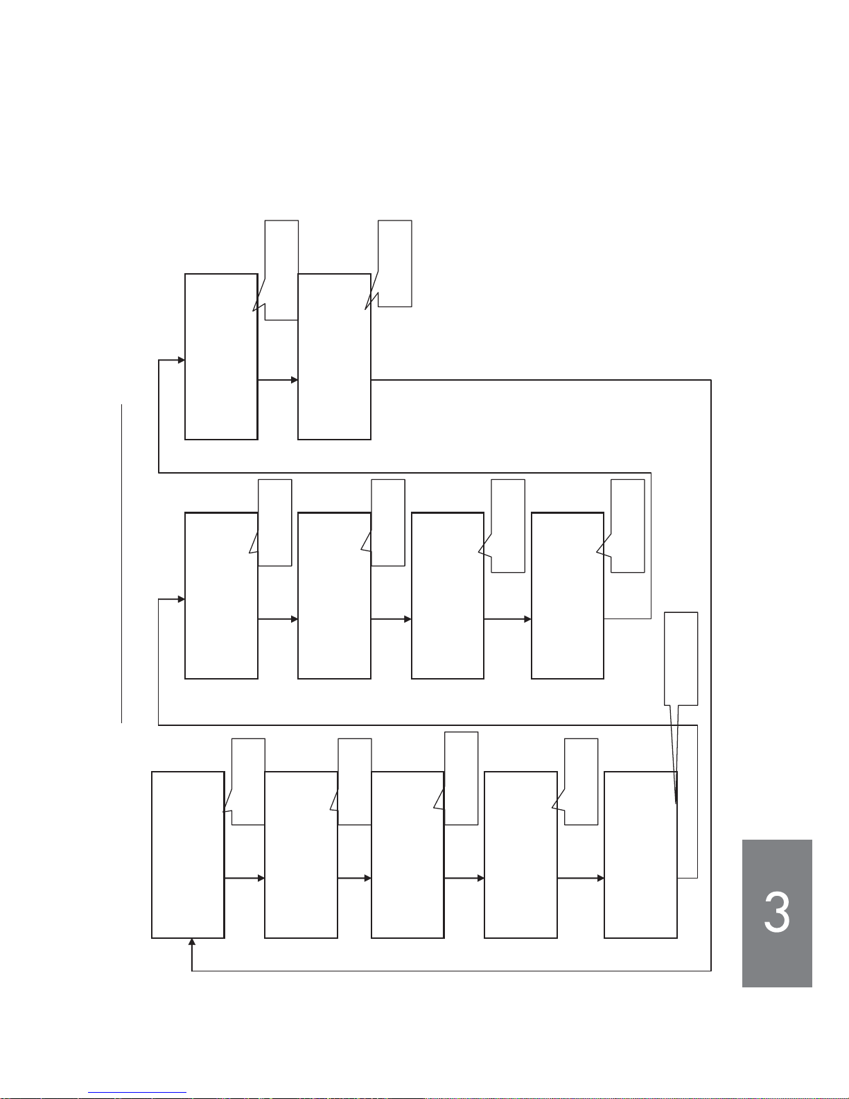
3:3 Trouble shooting
Diagnistics Tools
Hand Held Programmer
Plugging a Hand Held Programmer into the SHARK Remote when an abnormal condition exists
will cause the fault to be displayed. A 4-digit code will be displayed which indicates the condition.
The fi rst two digits provide the fl ach code number. The second two digits provide more specifi c
diagnostics information that is suitable for repair technicians.
In some cases, viewing a history of any abnormal conditions that occurred previously on the
system may be useful in diagnosting the current condition. This can be done by entering the
Fault Log from the Diagnostics menue. Usage statistics are also available from this menue.
DYNAMIC Wizard
Wizard is the preferred diagnostics tool in the workshop environment, providing a full fault history and verbal descriptions of each fl ash code.
If after analyzing the data, the condition can not be diagnosed, it is possible to print or safe a
Status Report for further analysis or distribution to a cervice centre.

77
Electrical system, work instructions
1. Fully charged batteries must be used when testing the electrical system
2. When fi tting batteries check that the polarity is correct.
3. When charging batteries connected in series, make sure that they are of equal capacity
i.e. same Ah and near exactly the same voltage on one decimal (i.e 12.82 V and 12.88V
may fi t together).
Electrical system, description
The Carony Go has a 24 V electrical system with two 12 V batteries connected in series. Voltage feed is supplied via a 50 A slow burn main fuse to the power module.
The power module distribute current and voltage to each of the three motors (drive motors and
lift motor) depending on the drivers demands. The power module also distribute feeding to the
lights and control unit.
Troubleshooting strategies
When a symptom or malfunction is detected the basis for troubleshooting is basic data collection.
• Customer information
• Dealer information
• Specifi cations (use the hand held programmer)
o Serial nr
o Machine hours
o Model year
• Flash codes
Description of malfunction or symptom
• Describe the problem
• When did the problem occur
• What happened just before the problem
Lead and connector checks
In an electrical system there is very important to check lead and connectors. Damaged electrical leads or loose connectors can cause malfunctions. Fuses are also to be checked before
any further troubleshooting.
Important!
• Testing should NOT be conducted by sticking objects through electrical lead insulation.
Use the proper electrical wiring diagram to fi nd suitable test points!
• Look for cable terminal oxidation
• Check for cable terminal damage, correct placement in the insulator.
• Check for good mechanical contact in the sockets.
3:3 Trouble shooting

78
3:3 Trouble shooting
The Carony Go and Drive is equipped with a self diagnose system which can tell the service
technician what kind of problem there is to fi nd. In the control unit there is a wrench which
fl ashes between 1-11 times.
You can use the hand held programmer or Wizard (not supplied to all dealers) or you can just
count the number of fl ashes.
When using the hand held programmer there is a four digit code in the display. The fi rst two
digits provide the fl ash code number. The second pair of nubers provide a sub-code for a more
specifi c fault message.
Flash
Code Fault Type Suggested actions
01 User fault Possible stall timeout or user error.
Release the joystick to normal and try again
02 Battery fault Check batteries and cables. Try changing the batteries
03 Left Motor fault Check the left motor, cables and connections
04 Right Motor fault Check the right motor, cables and connections
05 Left park brake fault Check the left park brake, cables and connections
06 Right park brake fault Check the right park brake, cables and connections
07 SHARK Control Unit fault Internal control unit fault. Replace control unit
08 SHARK Power Module fault Check SHARK connections and wiring. Replace
the power module.
09 SHARK communications fault Check SHARK connections and wiring. Replace the
SHARK Control Unit
10 Unknown fault Check all connections and wiring. Consult a service agent
11 Incompatible control unit Wrong type of Control Unit connected. Ensure the branding
of the Power Module matches that of the control unit.
DIAGNOSTICS
Flash Codes
Flashing wrench

79
3:3 Trouble shooting
DIAGNOSTICS
Code Fault source Sub code Meaning
M1
M2
When a motor fault occurs:
• Swap the motor connections: If the chair has two parking brakes, you can simply swap the motor connec-
tors on the Shark Power Module, if the connectors are not keyed.
If the chair has only one parkbrake, swap the motor connections at the mo-
tor end. This will swap the parkbrake connections too and rusult in a park-
brake fault with only one parkbrake, because it must be connected to M1.
• When after swapping the fault moves from motor 1 to motor 2 or vice versa, the fault is caused by the
motor or by the cables. Only when the fault does not move after swapping, the controller itself can be faulty.
01
02
03
04
User
Battery
Motor 1
Motor 2
00
00
00
01
02
03
04
06
All other
Out Of Neutral At Power Up (OONAPU) :
• Release the joystick to the centre and try again
Motor overload (too steep) :
• The motor is nort strong enough, try another route
Control unit is locked :
• Unlock the control unit
Voltage too high or too low :
• Check the batteries and the cables
• Batteries may be empty, charge the batteries.
• Batteries may be overcharged, if driving downhill slow down
• Batteries may be damaged, replace the batteries
Short circuit :
• Check the motor cables for damage
• Motor brushes may be too stiff, bouncing against the case.
Replace motor brushes or motor
Open circuit :
• Check if the motor cables are loose
• Motor brushes may be worn
Turn wheels to reconnect
or replace motor brushes or motor
Motor terminal connected to battery negative (-) :
• Check if the motor has been connected correctly
• Check the motor cables for damage
Motor terminal connected to battery positive (+) :
• Check if the motor has been connected correctly
• Check the motor cables for damage
Motor voltage not consitent during drive
• Possible motor short circuit
Check the motor cables for damage
or motor brushes may be too stiff and bouncing
• Otherwise internal controller fault, contact Dynamic
Intermittent short circuit
• Check for damaged cables
• Motor brushes may be too stiff, bouncing against the case
Replace motor brushes or motor
Internal fault
• Contact Dynamic
Continuation on next page

80
3:3 Trouble shooting
DIAGNOSTICS
Code Fault source Sub code Meaning
When a parkbrake fault occurs:
• Swap the motor/parkbrake connectors, if the motor connectors are not keyed.
• When after swapping the fault moves from Parkbrake 1 to the Prkbrake 2 or vice versa, the fault is in the
parkbrake or in the cables. Only when the fault does not move after swapping, the controller itself is faulty.
05
06
07
08
09
10
11
Parkbrake 1
Parkbrake 2
Remote
Power
Module
Communications
Internal fault
Wrong
remote
00
01
02
03
04
04
05
All other
13
14
All other
00
01
02
00
00
Drive-time test failed :
• Check the parkbrake cables.
Parbrake not connected or broken :
• Check if the cables of the parkbrake are loose.
Parkbarek short circuit or broken :
• Check the parkbrake cables for damage :
Fault during power-up testing :
• Check if parbrake cables are loose or damaged.
Parbrake short circuit or broken :
• Check the parkbrake cables for damage.
Attendant remote fault :
• Check attendant remote cables for damage
• Disconnect and reconnect attendant remote
• If fault doesn’t go away, disconnect the attendant remote as
a temporary solutution and contact Dynamic.
Internal fault :
• Contact Dynamic
Actuator fault :
• Check the actuator and the acteuator cables
Lighting fault :
• Check the light bulb and the lighting cables
Internal fault :
• Contact Dynamic
Loss of communication between remote and power module :
• Check for loose connectors or a damaged cable
• Check for worn motor brushes
Limp mode caused by unreliable communication :
• Check for loose connectors or a damaged cable
• Check for worn motor brushes
Loss of communication with attendant remote :
• Disconnect and reconnect attendant remote and try again.
• Check the attendant remote cables
• If the fault doesn’t go away, disconnect the attendant remote
as a temporary solution and contact Dynamic
• Contact Dynamic
Incompatible remote connected :
• Check that the brand on the remote and the power module
are the same.
continuation

81
3:3 Repair manual
3:4:1 Batteries, replace
3:4:2 Power module, replace
3:4:3 Joystick, dismount
3:4:4 Speedlimiter and height switch, replace

82
3:4 Repair manual
BATTERIES
3:4:1 Replace batteries
1. Remove the cover from the wheel unit.
Remove the battery clamp by fi rst unscrewing the
wing nut.
2. Disconnect the cable contacts and turn the
battery 90º (standing up).
3. Lift out the battery.
4. Pull the remaining battery as far back as possible and lift it out.
Disconnect the cables in the two removed batteries.
5. Connect the cables to the new batteries and
mount the new batteries in reversed order.
IMPORTANT: Both batteries must be replaced at the same time.
Always replace batteries of the same type and brand.

83
3:4 Repair manual
POWER MODULE
3:4:2 Replace Power module
4. Replace the power module and connect all the
contacts.
5. Fix the power module with the two screws.
6. Connect the batteries.
7. Check the functions of the new power module.
3. Lift up the power module as high as possible
and disconnect the contacts from the bottom side.
The contacts, counting from the left, are:
joystick, multi contakt, motor right side, battery
contact and motor left.
2. Unscrew the two screws fi xing the power
module.
1. Disconnect the battery contact by the fuse
holder.

84
3:4 Repair manual
3:4:3 Dismounting the joystick
JOYSTICK
1. Fold down the joystick arm and the joystick.
2. Remove the two hexagon screws that hold the
impact protection.
3. Remove the two counter sunk screws. Remove
the joystick and the cable protection.
4. Replace the joystick with a new and mount this
in reversed order.

85
3:4 Repair manual
3:4:4 Replacing the speed limiter/height switch
SPEED LIMITER / HEIGHT SWITCH
1. Remove the seat and the Velcro fastened plas-
tic cover.
Locate the microswitch.
2. Remove both the cables from the switch.
3. Unscrew the lock screw with a 2mm Allen
wrench, don’t remove it, just loosen it.
4. Remove the switch by pulling it out.
Remount in reversed order and verify the function.
Make sure that you don’t push the switch completely to the bottom, because it will then hit the pillar
when it travels. Just push it inwards and release it ½ mm or less, then tighten it.
Measure the switch with an ohm meter:
In raised position it should be infi nite ohms.
In lowered position it should be zero ohms.

86
Notes

87
Notes

Notes

Art. No: Not Available
Autoadapt Customer Support Centre (CSC)
Tel: +46 302 25440
Fax: +46 302 25407
E-mail: support@autoadapt.com
Autoadapt AB
Åkerivägen 7 S-443 61 Stenkullen Sweden
Tel: +46 302 25400
E-mail: contact@autoadapt.com
www.autoadapt.com www.autoadapt.de
www.autoadapt.fr www.autoadapt.se
 Loading...