

Page 1
Video Sender
A A
A
A A
UDIOUDIO
UDIO
UDIOUDIO
/V/V
/V
/V/V
IDEOIDEO
IDEO
IDEOIDEO
E E
XTENDERXTENDER
E
XTENDER
XTENDERXTENDER
E E
S S
S
S S
YSTEMYSTEM
YSTEM
YSTEMYSTEM
MM
ODELODEL
ODEL
M
ODELODEL
MM
((
INCLUDESINCLUDES
INCLUDES
(
INCLUDESINCLUDES
((
WVS100 WVS100
WVS100
WVS100 WVS100
WVS100S S WVS100S S
WVS100S S
WVS100S S WVS100S S
OWNER'S MANUALOWNER'S MANUAL
OWNER'S MANUAL
OWNER'S MANUALOWNER'S MANUAL
& WVS100R R & WVS100R R
ENDERENDER
ENDER
& WVS100R R
ENDERENDER
& WVS100R R & WVS100R R
ECEIVERECEIVER
ECEIVER
ECEIVERECEIVER
))
)
))
Page 2
I I
NTRODUCTIONNTRODUCTION
I
NTRODUCTION
NTRODUCTIONNTRODUCTION
I I
Your Wireless Video Sender kit consists of a Sender base unit
which connects to your DBS™ receiver, DVD player, VCR, or cable
box, and a Receiver unit which connects to the TV in another room.
The Video Sender converts the A/V signal from your DBS, etc.,
into a radio signal and transmits it (even through walls) to the
Video Receiver unit. The Video Receiver converts the signals back
to A/V signals which are fed through a cable to your TV's A/V
input jacks.
CC
ONTENTSONTENTS
C
ONTENTS
ONTENTSONTENTS
CC
CC
ONTROLSONTROLS
ONTROLS
C
ONTROLSONTROLS
CC
BB
B
BB
BB
B
BB
CC
ONNECTINGONNECTING
ONNECTING
C
ONNECTINGONNECTING
CC
HH
H
HH
OTTOMOTTOM
OTTOM
OTTOMOTTOM
V V
ACKACK
V
ACK
ACKACK
V V
OOKINGOOKING
OOKING
OOKINGOOKING
C C
ANDAND
AND
ANDAND
V V
V
V V
IEWSIEWS
IEWS
IEWSIEWS
UPUP
UP
UPUP
ONNECTIONSONNECTIONS
ONNECTIONS
C
ONNECTIONSONNECTIONS
C C
IEWSIEWS
IEWS
...................................................................
IEWSIEWS
............................................
.......................................................................
U U
PP
P
..................................................................
U
PP
U U
V V
V
V V
IDEOIDEO
IDEO
IDEOIDEO
S S
S
S S
ENDERENDER
ENDER
...........................................
ENDERENDER
THETHE
THE
THETHE
FCC CFCC C
FCC C
FCC CFCC C
THIS DEVICE COMPLIES WITH PART 15 OF THE FCC RULES.
OPERATION IS SUBJECT TO THE FOLLOWING TWO CONDITIONS:
(1)THIS DEVICE MAY NOT CAUSE HARMFUL INTERFERENCE, AND
(2)THIS DEVICE MUST ACCEPT ANY INTERFERENCE RECEIVED, INCLUDING
This equipment generates and uses radio frequency energy, and if not installed and
used properly, that is, in strict accordance with the manufacturers instructions, it may
cause interference to radio and television reception. It has been type tested and
found to comply with the limits for remote control devices in accordance with the
specifications in Sub-Parts B and C of Part 15 of FCC Rules, which are designed to
provide reasonable protection against such interference in a residential installation.
However, there is no guarantee that interference will not occur in a par ticular
installation. If this equipment does cause interference to radio or television reception,
which can be determined by unplugging the equipment, try to correct the interference
by one or more of the following measures.
44
4
44
44
4
44
55
5
55
66
6
66
66
6
66
• Reorient the antenna of the radio/TV experiencing the interference.
• Relocate the equipment with respect to the radio/TV.
• Move the equipment away from the radio/TV.
• Plug the equipment into an outlet on a different electrical circuit from the radio/TV
• If necessary, consult your local Dealer for additional suggestions.
NOTE:NOTE:
NOTE: Modifications to this product will void the user's authority to operate this
NOTE:NOTE:
equipment.
AUTIONAUTION
AUTION
AUTIONAUTION
INTERFERENCE THAT MAY CAUSE UNDESIRED OPERATION.
experiencing the interference.
FF
F
FF
INEINE
INE
INEINE
HH
OOKINGOOKING
H
OOKING
OOKINGOOKING
HH
II
FF
YOUYOU
F
YOU
I
FF
YOUYOU
II
FROMFROM
FROM
FROMFROM
TUNINGTUNING
TUNING
TUNINGTUNING
YOURYOUR
YOUR
YOURYOUR
WW
W
WW
UPUP
UP
UPUP
ANTANT
ANT
ANTANT
S S
S
S S
YOURYOUR
YOUR
YOURYOUR
V V
THETHE
V
THE
THETHE
V V
TOTO
TO
TOTO
TEREOTEREO
TEREO
TEREOTEREO
USEUSE
USE
USEUSE
V V
V
V V
IDEOIDEO
IDEO
IDEOIDEO
S S
S
S S
YOURYOUR
YOUR
YOURYOUR
YSTEMYSTEM
YSTEM
YSTEMYSTEM
IDEOIDEO
IDEO
IDEOIDEO
R R
R
R R
ECEIVERECEIVER
ECEIVER
ECEIVERECEIVER
V V
V
V V
S S
S
S S
.........................................
S S
IDEOIDEO
S
IDEO
IDEOIDEO
S S
ONLONL
YY
ONL
Y
..........................................
ONLONL
YY
ENDERENDER
ENDER
ENDERENDER
22
2
22
TOTO
TO
TOTO
TRANSMITTRANSMIT
TRANSMIT
TRANSMITTRANSMIT
ENDERENDER
ENDER
ENDERENDER
..................................
88
8
88
99
9
99
1010
10
1010
33
3
33
Page 3
C C
ONTROLSONTROLS
C
ONTROLS
ONTROLSONTROLS
C C
ANDAND
AND
ANDAND
C C
ONNECTIONSONNECTIONS
C
ONNECTIONS
ONNECTIONSONNECTIONS
C C
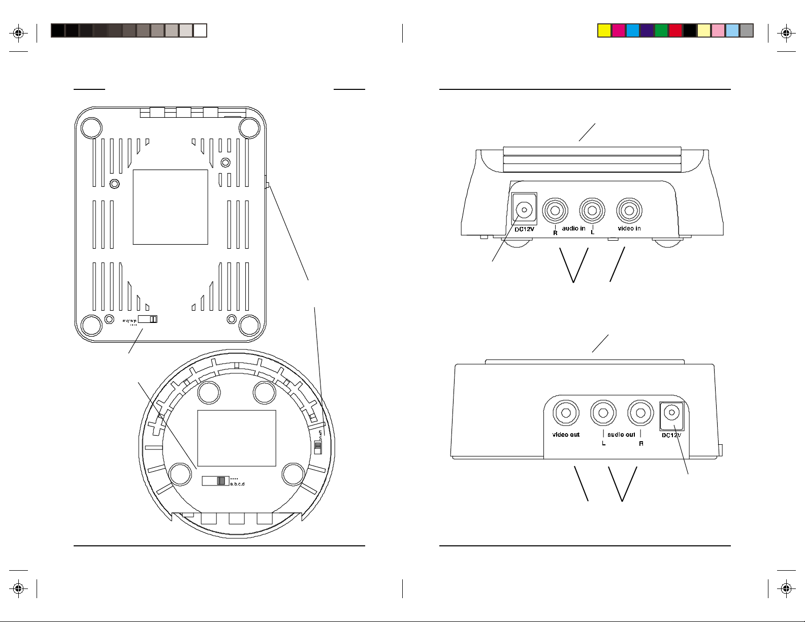
2.4 GHz
Channel Switch
VV
R R
IDEOIDEO
V
VV
((
BOTTOMBOTTOM
(
BOTTOM
BOTTOMBOTTOM
((
ECEIVERECEIVER
R
IDEO
ECEIVER
IDEOIDEO
ECEIVERECEIVER
R R
V V
V
V V
On-Off Switch
IEWIEW
IEW
IEWIEW
VV
S S
IDEOIDEO
V
VV
((
BACKBACK
(
BACK
BACKBACK
((
))
)
))
VV
V
VV
((
BACKBACK
(
BACK
BACKBACK
((
ENDERENDER
S
IDEO
ENDER
IDEOIDEO
ENDERENDER
S S
VIEWVIEW
VIEW
VIEWVIEW
Power Supply
Jack
R R
IDEOIDEO
ECEIVERECEIVER
R
IDEO
ECEIVER
IDEOIDEO
ECEIVERECEIVER
R R
VIEWVIEW
VIEW
VIEWVIEW
))
)
))
))
)
))
2.4 GHz Video
Antenna
A/V Input
Jacks
2.4 GHz Video
Antenna
VV
IDEOIDEO
IDEO
V
IDEOIDEO
VV
((
BOTTOMBOTTOM
(
BOTTOM
BOTTOMBOTTOM
((
S S
S
S S
ENDERENDER
ENDER
ENDERENDER
V V
IEWIEW
V
IEW
IEWIEW
V V
Power Supply
))
)
))
44
4
44
A/V Output
Jacks
55
5
55
Jack
Page 4

HH
OOKINGOOKING
OOKING
H
OOKINGOOKING
HH
C C
ONNECTINGONNECTING
C
ONNECTING
ONNECTINGONNECTING
C C
THETHE
THE
THETHE
V V
V
V V
UPUP
UP
UPUP
IDEOIDEO
IDEO
IDEOIDEO
S S
S
S S
ENDERENDER
ENDER
ENDERENDER
U U
U
U U
PP
P
PP
1 . Connect one set of Audio/Video cables to the VIDEO and
AUDIO jacks of your Video Sender. Take care to match the
colors of the plugs on the cable with the jacks on the Video
Sender.
2 . Connect the other end of the cable to the Audio/Video OUT
jacks on your primar y TV (the one you want to send the picture
FROM). Take care to match the colors of the plugs on the cable
with the jacks on the TV. If the jacks on the TV are colored
differently, connect the yellow plug to the jack labelled VIDEO,
the red plug to the jack labelled AUDIO RIGHT and the white
plug to the jack labeled AUDIO LEFT.
Note:Note:
Note: If your TV does not include Audio/Video OUT jacks, you
Note:Note:
will need to remake the connections as shown in diagram b)
using the TV antenna (coaxial) connections to link up the DBS
Receiver/Cable Box/VCR to your TV.
A/V Cable
DC12V
LR
TV
OUT
AUDIO
VIDEO
IN
OUT
AUDIO
VIDEO
DBS
ANTENNA
TO TV
ANTENNA
Coaxial
Cable
3 . Plug the Video Sender's Power Supply (the smaller of the two
power supplies) into a convenient 120 volt wall outlet and plug
its jack into the Video Sender.
4 . Position the Video Sender in a convenient location such as on
top of the TV and orient the antenna so that the flat side points
in the direction of the room where you will be installing the
Video Receiver.
II
FF
YOUYOU
I
F
YOU
FF
YOUYOU
II
HAHA
VEVE
SEVERALSEVERAL
HA
VE
SEVERAL
HAHA
VEVE
SEVERALSEVERAL
A/V A/V
A/V
A/V A/V
COMPONENTSCOMPONENTS
COMPONENTS
COMPONENTSCOMPONENTS
If you have two or more A/V
components (e.g. DBS, VCR, Cable
Box, Video Disk etc.) that you want to
watch in another room, they will
probably already be hooked up to the
local TV in series (see the diagram to
the right). To connect the Video Sender
you just need to identify the last
component in the chain and connect its
LINE OUT jacks to the Video Sender's
LINE IN jacks.
If the last component in the chain does
not have spare LINE OUT jacks,
reconnect the local TV to the last
component in the chain using coaxial
cables to connect the VHF/UHF ports,
then use the A/V connections for the
Video Sender.
a) Connections for a TV
with A/V OUT jacks.
b) Connections for a TV
without A/V OUT jacks.
66
6
66
77
7
77
Page 5

HH
OOKINGOOKING
OOKING
H
OOKINGOOKING
HH
THETHE
THE
THETHE
V V
V
V V
UPUP
UP
UPUP
IDEOIDEO
IDEO
IDEOIDEO
R R
ECEIVERECEIVER
ECEIVER
R
ECEIVERECEIVER
R R
1. Connect a set of Audio/Video
cables to the A/V OUT jacks of
your Video Receiver. Connect the
other end to your secondar y TV.
2 . Plug the Video Receiver's Power
Supply (the larger of the two power
supplies) into a 120 volt wall outlet
and plug its jack into the Video
Receiver.
3 . Position the Video Receiver in a
convenient location such as on top
of the TV and orient the antenna so
that the flat side points in the
direction of the room where you set up the Video Sender.
II
TV TV
FF
YOURYOUR
I
TV
F
YOUR
FF
YOURYOUR
II
TV TV
DOESDOES
DOES
DOESDOES
NOTNOT
NOT
NOTNOT
A/V A/V
HAHA
VEVE
HA
VE
HAHA
VEVE
A/V
A/V A/V
CONNECTORSCONNECTORS
CONNECTORS
CONNECTORSCONNECTORS
You can will need to purchase an RF modulator.
II
FF
YOURYOUR
I
F
YOUR
FF
YOURYOUR
II
OTHEROTHER
OTHER
OTHEROTHER
A/V A/V
A/V
A/V A/V
SECONDSECOND
SECOND
SECONDSECOND
DEVICEDEVICE
DEVICE
DEVICEDEVICE
TV TV
TV
TV TV
ISIS
ALREADYALREADY
IS
ALREADY
ISIS
ALREADYALREADY
HOOKEDHOOKED
HOOKED
HOOKEDHOOKED
If your DBS Receiver or other A/V
component is connected to the TV
using A/V cables, you can connect
the Video Receiver to the free LINE IN
jacks on the component. If there are
no LINE IN jacks, you will need to
purchase an RF modulator.
II
FF
YOUYOU
F
YOU
I
FF
YOUYOU
II
FROMFROM
FROM
FROMFROM
YOURYOUR
YOUR
YOURYOUR
WW
W
WW
ANTANT
ANT
ANTANT
S S
S
S S
TOTO
TO
TOTO
TEREOTEREO
TEREO
TEREOTEREO
USEUSE
USE
USEUSE
S S
S
S S
YOURYOUR
YOUR
YOURYOUR
YSTEMYSTEM
YSTEM
YSTEMYSTEM
V V
V
V V
IDEOIDEO
IDEO
IDEOIDEO
ONLONL
ONL
ONLONL
Just hook up the Video Sender using
only the red and white jacks for the
right and left channels of the audio
signal. Leave the yellow (video) jacks
unconnected.
TOTO
TO
TOTO
ENDERENDER
ENDER
ENDERENDER
DBS R DBS R
AA
DBS R
A
AA
DBS R DBS R
TOTO
TO
TOTO
TRANSMITTRANSMIT
TRANSMIT
TRANSMITTRANSMIT
UPUP
UP
UPUP
S S
S
S S
YY
Y
YY
ECEIVERECEIVER
ECEIVER
ECEIVERECEIVER
OROR
OR
OROR
88
8
88
99
9
99
Page 6

F F
F
F F
The Wireless Video Sender usually works best with the flat faces of
the antennas on the Sender and Receiver unit facing each other
(i.e. see diagram below). Sometimes, however, reflections and
other effects in the home may affect the signal so that some
adjustment of either the Sender or Receiver antenna may be
necessary to get the best the signal.
II
FF
YOUYOU
I
F
YOU
FF
YOUYOU
II
Check that the CHANNEL slide switch (labeled A to D) on both
units is set to the same letter.
T T
INEINE
T
INE
INEINE
T T
TT
RANSMITTERRANSMITTER
T
RANSMITTER
RANSMITTERRANSMITTER
TT
AREARE
NOTNOT
ARE
NOT
AREARE
NOTNOT
UNINGUNING
UNING
UNINGUNING
GETTINGGETTING
GETTING
GETTINGGETTING
Printed sides of
antennas should face
each other
ANYANY
ANY
ANYANY
YOURYOUR
YOUR
YOURYOUR
SIGNALSIGNAL
SIGNAL
SIGNALSIGNAL
V V
V
V V
AA
A
AA
TT
T
TT
IDEOIDEO
IDEO
IDEOIDEO
ALLALL
ALL
ALLALL
S S
S
S S
RR
ECEIVERECEIVER
R
ECEIVER
ECEIVERECEIVER
RR
ENDERENDER
ENDER
ENDERENDER
90 D90 D
90 D
90 D90 D
HelplineHelpline
Helpline
HelplineHelpline
If you need additional setup help, please call the Helpline at:
1-800-420-7968
Thomson Consumer Electronics, Inc. warrants that for 90 days from
date of purchase, it will replace this product if found to be defective
in materials or workmanship. Return it postage prepaid to the Product
Exchange Center address for prompt, no charge replacement with a
current equivalent. This replacement is Thomson Consumer Electronics,
Inc.’s sole obligation under this warranty. Thomson Consumer
Electronics, Inc. will not be responsible for any incidental or
consequential damages, or for any loss arising in connection with
the use or inability to use this product. Some states do not allow the
exclusion or limitation of incidental or consequential damages, so
the above limitation or exclusion may not apply to you. This warranty
excludes defects or damage due to misuse, abuse, or neglect. This
warranty gives you specific legal rights, and you may also have
other rights, which vary from state to state.
© 2000 Thomson Consumer Electronics, Inc.
Product Exchange Center
11721 Alameda Ave.
Socorro, TX 79927
Trademark(s) ® Registered Marca(s) Registrada(s)
Made in China
AA
A
AA
YY
Y
YY
L L
L
L L
IMITEDIMITED
IMITED
IMITEDIMITED
W W
W
W W
ARRANTYARRANTY
ARRANTY
ARRANTYARRANTY
II
FF
THETHE
I
F
THE
FF
THETHE
II
Try changing the channel on both units. Do this by adjusting the
CHANNEL slide switch on each Video Sender/Receiver unit to any
position from A-D. Make sure both units are set to the same
channel. Make sure the printed side of both antennas is facing
each other.
SIGNALSIGNAL
SIGNAL
SIGNALSIGNAL
, ,
ISIS
POORPOOR
OROR
IS
POOR
ISIS
POORPOOR
THERETHERE
,
OR
THERE
OROR
THERETHERE
, ,
ISIS
INTERFERENCEINTERFERENCE
IS
INTERFERENCE
ISIS
INTERFERENCEINTERFERENCE
1010
10
1010
1111
11
1111
Page 7

Thomson Consumer Electronics, Inc.Thomson Consumer Electronics, Inc.
Thomson Consumer Electronics, Inc.
Thomson Consumer Electronics, Inc.Thomson Consumer Electronics, Inc.
Product Exchange CenterProduct Exchange Center
Product Exchange Center
Product Exchange CenterProduct Exchange Center
11721 Alameda A11721 Alameda A
11721 Alameda A
11721 Alameda A11721 Alameda A
Socorro, TX 79927Socorro, TX 79927
Socorro, TX 79927
Socorro, TX 79927Socorro, TX 79927
ve.ve.
ve.
ve.ve.
WVS100-7/01
 Loading...