

Page 1
VGA Video Sender
OWNER'S MANUAL
MODEL VK60A
(INCLUDES VT36A SENDER AND VR30A RECEIVER)
VT36AVR30A
Page 2
INTRODUCTION
FCC CAUTION
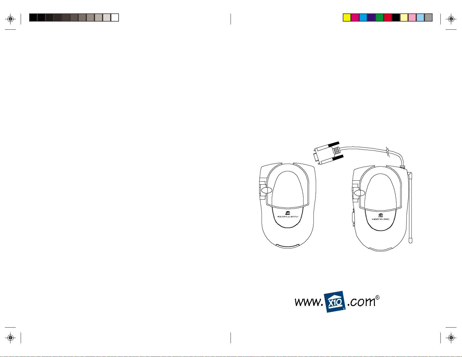
Your Wireless Big Picture VGA Video Sender kit consists of a Sender
base unit which connects to the audio out jack and the VGA output
on your PC, and a Receiver unit which you connect to your TV. The
Sender converts the audio signal from your PC's sound card, and the
VGA video from your PC's video card into a radio frequency (RF)
signal and transmits it (even through walls) to the Receiver unit. The
Receiver converts the signals back to their original form and passes
them to your TV.
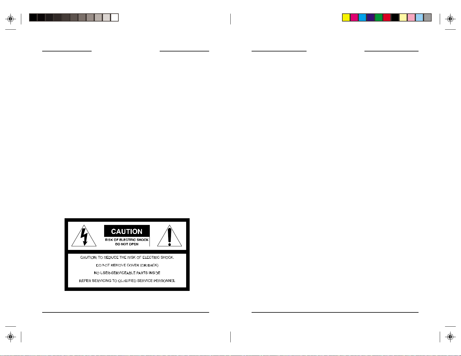
WARNING:
To reduce the risk of fire or electric shock, do not expose this product
to rain or moisture.
THIS DEVICE COMPLIES WITH PART 15 OF THE FCC RULES.
OPERATION IS SUBJECT TO THE FOLLOWING TWO CONDITIONS:
(1)THIS DEVICE MAY NOT CAUSE HARMFUL INTERFERENCE, AND
(2)THIS DEVICE MUST ACCEPT ANY INTERFERENCE RECEIVED, INCLUDING
INTERFERENCE THAT MAY CAUSE UNDESIRED OPERATION.
This equipment generates and uses radio frequency energy, and if not installed and
used properly, that is, in strict accordance with the manufacturers instructions, it may
cause interference to radio and television reception. It has been type tested and found
to comply with the limits for remote control devices in accordance with the
specifications in Sub-Parts B and C of Part 15 of FCC Rules, which are designed to
provide reasonable protection against such interference in a residential installation.
However, there is no guarantee that interference will not occur in a particular
installation. If this equipment does cause interference to radio or television reception,
which can be determined by unplugging the equipment, try to correct the interference
by one or more of the following measures.
• Reorient the antenna of the radio/TV experiencing the interference.
• Relocate the equipment with respect to the radio/TV.
• Move the equipment away from the radio/TV.
• Plug the equipment into an outlet on a different electrical circuit from the radio/TV
experiencing the interference.
• If necessary, consult your local Dealer for additional suggestions.
NOTE: Modifications to this product will void the user's authority to operate this
equipment.
SYSTEM REQUIREMENTS
To use the Big Picture system your PC must have a serial port, a VGA
out port (that normally connects to your monitor) and a sound card
with mono or stereo output.
32
Page 3
CONTENTS
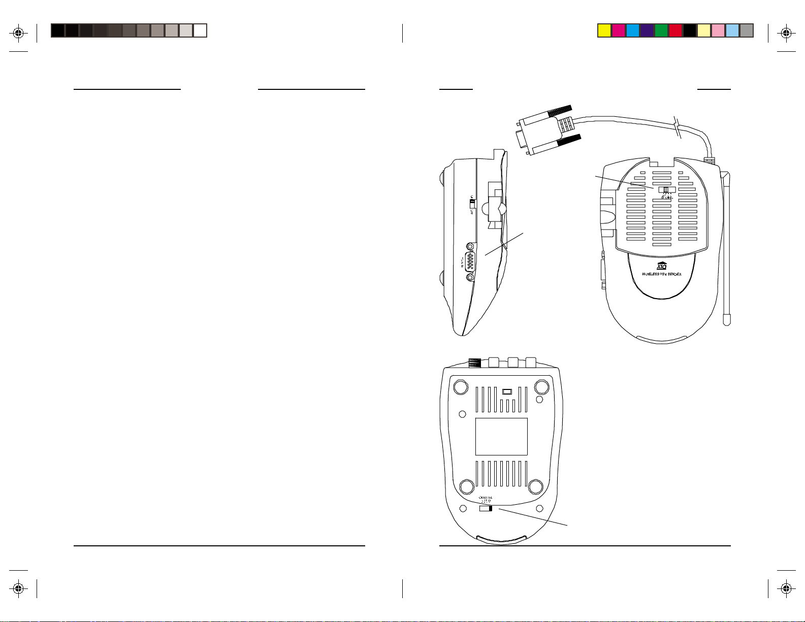
CONTROLS AND CONNECTIONS
CONTROLS AND CONNECTIONS
ENDER
..........................................................................6
S
R
ECEIVER
........................................................................7
.................................................5
BEFORE YOU START .................................................................8
ONNECTING UP
C
H
OOKING UP THE SENDER
H
OOKING UP THE RECEIVER
FINE TUNING YOUR SYSTEM
ROUBLESHOOTING
T
..................................................................
....................................................
.................................................
....................................................12
..............................................................13
10
Serial port
connector
9
9
S
ENDER
(S
IDEVIEW
2.4 GHz
Channel Switch
VGA In
)
S
ENDER
(TOP V
IEW
)
R
ECEIVER
(B
OTTOM VIEW
2.4 GHz
Channel Switch
54
)
Page 4

S
ENDER
310 MHz Antenna for
use with UR81A remote
R
ECEIVER
2.4 GHz Channel
Switch
Serial port
connector
2.4 GHz
Video
Antenna
Audio Input
Jacks
ON-OFF
Switch
(on side)
Power Supply
Jack
TV Output
Connector
TV Channel
Switch
(on bottom)
A/V Input
Jacks
2.4 GHz
Video
Antenna
ON-OFF
Switch
(on side)
Power Supply
Jack
2.4 GHz Channel
Switch
(on bottom)
76
Page 5

BEFORE YOU START
Before you start installing your Big Picture System it is recommended
that you read this entire owner's manual. This will familiarize you
with the basic hardware installation. Then install the hardware. You
will then be able to see a picture from your PC on our TV screen. You
can then visit www.x10.com/software and download the "Boom"
program there, which will give you control over what is sent from
your PC to your TV.
CONNECTING UP
HOOKING UP THE VGA SENDER
1. Connect the jack on the audio cable (supplied) to the audio out
jack on your PC sound card.
2. Connect the red RCA plug to the socket labelled AUDIO RIGHT
and the white RCA plug to the jack labeled AUDIO LEFT on the
VGA Video Sender.
3. Connect the VGA cables as show below so that the VGA out from
your PC connects to the VGA input on the VT36A and then also
passes to the VGA input on your monitor.
4. Connect the serial port connector to your PC's serial port.
5. Set the channel switch (on the TOP of the unit) to channel A (to the
RIGHT).
6. Plug the VGA Video Sender's Power Supply (the smaller of the
two power supplies) into a convenient 120 volt wall outlet and
plug its jack into the VGA Video Sender.
7. Position the VGA Video Sender in a convenient location and
orient the antenna so that the flat side points in the direction of the
room where you will be installing the Video Receiver.
Serial port connecter
98
Page 6

HOOKING UP THE AUDIO RECEIVER
1. Connect a set of Audio/Video cables to the A/V OUT jacks of
your Video Receiver. Connect the other end to your secondary TV.
2. Plug the Video Receiver's Power Supply (the larger of the two
power supplies) into a 120 volt wall outlet and plug its jack into
the Video Receiver.
3. Position the Video Receiver in a convenient location such as on
top of the TV and orient the antenna so that the flat side points in
the direction of the room where you set up the Video Sender.
IF
YOUR
TV
DOES NOT HAVE
You can use the supplied
coaxial cable to connect the
TV OUT socket on the Video
Receiver to the Antenna
input on your TV. If you
already have an antenna
connected to your TV, you
will need to use a TV
antenna splitter.
Set your TV and the TV
Channel switch on the
Video Receiver (on bottom)
to the same channel (3 or 4).
A/V
CONNECTORS
IF
YOUR SECOND
OTHER
A/V
TV IS
DEVICE
ALREADY HOOKED UP TO A
If your DBS Receiver or other A/V
component is connected to the TV using
A/V cables, you can connect the Video
Receiver to the free LINE IN jacks on
the component. If there are no LINE IN
jacks, you will need to use a TV
antenna splitter as described earlier.
1110
DBS R
ECEIVER OR
Page 7

FINE TUNING YOUR SYSTEM
The Wireless VGA Video Sender usually works best with the flat faces
of the antennas on the Sender and Receiver units facing each other
(see diagram below). Sometimes, however, reflections and other
effects in your home may affect the signal so that some adjustment of
either the Sender or Receiver antenna might be necessary to get the
best the signal.
TROUBLESHOOTING
IF
YOU ARE NOT GETTING ANY AUDIO OR VIDEO AT ALL FROM THE
VR30A
• Check that the CHANNEL slide switch (labeled A, B, C, D) on both
units is set to the same letter.
• Check that both the transmitter and receiver's power supplies are
plugged in. Check that the ON/OFF switch on the transmitter and
receiver are ON.
IF
THE SOUND OR VIDEO IS POOR, OR THERE IS INTERFERENCE
• Try changing the channel on both units. Do this by adjusting the
CHANNEL slide switch on each unit to any position (A, B, C, or
D).
• Make sure both units are set to the same letter. Try repositioning
the antenna on each unit.
1312
Page 8

NOTES
12 MONTH LIMITED WARRANTY
X10.COM A DIV. OF X10 WIRELESS TECHNOLOGY, INC. (X10)
WARRANTS ITS PRODUCTS TO BE FREE FROM DEFECTIVE MATERIAL AND
WORKMANSHIP FOR A PERIOD OF ONE (1) YEAR FROM THE ORIGINAL
DATE OF PURCHASE AT RETAIL. X10 AGREES TO REPAIR OR REPLACE, AT
ITS SOLE DISCRETION, A DEFECTIVE X10 PRODUCT IF RETURNED TO X10
WITHIN THE WARRANTY PERIOD AND WITH PROOF OF PURCHASE.
IF SERVICE IS REQUIRED UNDER THIS WARRANTY:
1. CALL 1-800-675-3044, OR VISIT WWW.X10.COM, OR E-MAIL
SALES@X10.COM TO OBTAIN A RETURN AUTHORIZATION (RA)
NUMBER.
2. RETURN THE DEFECTIVE UNIT POSTAGE PREPAID TO THE ADDRESS
ON BACK.
3. ENCLOSE A CHECK FOR $4.00 TO COVER HANDLING AND RETURN
POSTAGE.
4. ENCLOSE A DATED PROOF OF PURCHASE.
5. X10 IS NOT RESPONSIBLE FOR SHIPPING DAMAGE. UNITS TO BE
RETURNED SHOULD BE PACKED CAREFULLY.
THIS WARRANTY DOES NOT EXTEND TO ANY X10 PRODUCTS WHICH
HAVE BEEN SUBJECT TO MISUSE, NEGLECT, ACCIDENT, INCORRECT
WIRING OR TO USE IN VIOLATION OF OPERATING INSTRUCTIONS
FURNISHED BY US, NOR EXTEND TO ANY UNITS ALTERED OR REPAIRED
FOR WARRANTY DEFECT BY ANYONE OTHER THAN X10. THIS
WARRANTY DOES NOT COVER ANY INCIDENTAL OR CONSEQUENTIAL
DAMAGES AND IS IN LIEU OF ALL OTHER WARRANTIES EXPRESSED OR
IMPLIED AND NO REPRESENTATIVE OR PERSON IS AUTHORIZED TO
ASSUME FOR US ANY OTHER LIABILITY IN CONNECTION WITH THE
SALE OF OUR PRODUCTS.
SOME STATES DO NOT ALLOW LIMITATIONS ON HOW LONG AN
IMPLIED WARRANTY LASTS, AND/OR THE EXCLUSION OR LIMITATION
OF INCIDENTAL OR CONSEQUENTIAL DAMAGES SO THE ABOVE
LIMITATIONS AND EXCLUSIONS MAY NOT APPLY TO THE ORIGINAL
CUSTOMER. THIS WARRANTY GIVES YOU SPECIFIC RIGHTS AND YOU
MAY ALSO HAVE OTHER RIGHTS WHICH VARY FROM STATE TO STATE.
Page 9

X10.com, a division of X10 Wireless Technology, Inc.
(Returns Depot), 3824 North 5th St., Suite C,
North Las Vegas, NV 89030
VK60A-04/01
 Loading...