

Page 1
Page 2

Trademark Acknowledgement
EVO™, Autel Explorer™, Starpoint™ and the Autel Robotics® logo are
trademarks of Autel Robotics Co., Ltd., registered in China, the United States and
other countries. All other products and company names mentioned in this User
Manual are registered trademarks of their respective holders.
Copyright Warning
Reproduction or retransmission of any part of this manual in any form or by any
means, whether electronic, mechanical, photocopying, recording, or otherwise, is
forbidden without the express written permission of Autel Robotics.
Disclaimer
Please closely follow the steps in these instructions in order to ensure safe and
successful operation of your EVO aircraft.
EVO should only be used by children while under close adult supervision. We
strongly recommend making sure that kids can’t access the aircraft when it’s idle.
Autel Robotics provides no warranty coverage for product damages that occur
during use if the customer fails to follow the safety instructions, and neither is
it liable for any damages incurred during product use, be they direct or indirect,
legal, special, incidental, or economic (including but not limited to loss of prots).
Do not use incompatible components or attempt to modify EVO in any way
inconsistent with the instructions in the ofcial aircraft documentation.
These safety instructions will show you the steps to get started safely with EVO.
Only you can ensure that you y EVO securely and never jeopardize the safety of
yourself, other people, or their property.
Our safety instructions will be updated over time. To make sure you have the
latest version, visit www.autelrobotics.com/support/downloads/.
Data Storage and Usage
When the backup service is disabled, as it is by default, no ight or user data
will be uploaded or transmitted via the mobile app. When the Autel ExplorerTM
mobile app is paired with the aircraft, ight log data, including ight telemetry,
will be uploaded and maintained on Autel Robotics data servers. All telemetry
and ight logs are stored on data servers located within the boundaries of the
continental United States, and the data upload occurs automatically only if the
Flight Log Backup option is enabled.
The Autel customer service team doesn’t have access to ight log data except
Page 3

when explicitly granted permission by the user via the mobile app. When that
permission is granted, only ight logs within the selected date range will be
accessed.
Information, including still and motion imagery and data from the aircraft’s
sensors, will be stored on the EVO’s internal drive. If your aircraft ever needs to
be sent to us for service, the information on the internal storage unit may be used
to diagnose problems with the aircraft. The information will not be retained except
as required to process the service or repair. Do not remove or alter the data on the
internal storage device in any way. Doing so will invalidate all warranty coverage.
Autel Robotics’ purpose in gathering data is to provide support and service for our
customers, and to improve the performance of our products. We take your privacy
as seriously as we do our own. We will consent to the disclosure of uploaded data
only when required by law to do so.
Safety Instructions
Battery Safety
A lithium-polymer battery powers the aircraft. The misuse of Li-Po/Li-Ion batteries
can be hazardous. As such, make sure to follow all the battery usage, charging
and storage instructions below.
WARNING
• The battery is factory-replaceable only. Do not tamper with either the
battery pack or its charger, or replace them with third-party devices.
• Battery electrolytes are highly corrosive. If any electrolyte is splashed
onto your skin or in your eyes, immediately wash the affected area with
fresh running water and consult a doctor.
Battery Usage
Always remember to turn off the aircraft before installing or removing the battery.
Other notes:
• Only use the battery and charger provided by Autel Robotics. An unapproved
battery or charger may result in re, explosion, leakage or other hazards.
Autel Robotics takes no responsibility for any damage caused by the third
party batteries or charging devices
• When not in use, remove the battery from the aircraft to prevent trickle
discharge
• Keep the battery stored in a safe, dry, warm environment
• Do not disassemble, open, crush, bend, deform, puncture, or shred the battery
Page 4

• Do not modify, remanufacture, or attempt to insert foreign objects into the
battery
• Do not place heavy objects on the battery or charger
• Stop using or charging the battery immediately if it starts to swell, smoke or
leak
• Use the battery at temperatures between -10°C and 40°C. Extremely
high temperatures may cause a re or explosive damage; extremely low
temperatures may lead to permanent battery damage
• Before ying in a low-temperature environment (between -10°C and 15°C),
fully charge the battery in warmer temperatures, or insert it into EVO and
hover the aircraft at an altitude of 1m until the battery warms up to 15°C or
higher. The battery temperature can be monitored using the mobile app
• Do not use the battery in strong electrostatic or electromagnetic environments
• Do not expose the battery to re, explosions, or other hazards
• The heavier the aircraft loads, the shorter the ight time
If the aircraft falls into the water, remove the battery immediately after you retrieve
it. Leave the battery in an open area and maintain a safe distance until it is
completely dry. Don’t use the battery again. Contact our customer support team
for a replacement.
Battery Charging
It should take a maximum of 80 minutes to fully charge the EVO battery, though
charging times will vary according to the remaining battery level. Other battery
charging notes and words of caution:
• Do not use a damaged battery charger
• When the charger is not in use, we recommend disconnecting it
• Do not charge the battery immediately after ight, as overheat protection will
prevent the battery from being charged before it cools completely
• Overcharging may shorten battery life, so don’t leave the battery unattended
during charging, and remove it after it’s fully charged
We strongly recommend that you go through a charge cycle — wherein you
charge the battery to 100% and then discharge it to 7% or lower — every three
months, or after the battery has been used for 20 consecutive charges.
Battery Storage
In storage as in ight, it’s important not to allow the battery to come in close
contact with moisture or heat sources. Store the battery in a dry and ventilated
area at room temperature (ideally 22°C to 28°C). Other storage notes:
• Keep the battery out of reach of children and pets
Page 5

• Do not place the battery next to sharp items, or on a conductive surface (e.g.,
metal plate)
• Do not put the battery in the wet grass or pocket with metal objects
• Make sure the battery voltage level does not fall below 3V during storage
• Using or storing the battery in extreme environments may reduce overall
battery life
• Because battery life inevitably shortens over time, the life of your battery may
be reduced if it is left unused over an extended period
Battery Disposal
• Completely discharge the battery before disposal
• Dispose of the battery properly at an approved battery recycling location
Flying EVO Safely & Securely
Take-off & Landing
Place the aircraft on a level, open surface and stand at a distance of at least 5
meters to its rear. If possible, we highly recommend having an experienced pilot
on hand during your rst ight. Other takeoff and landing guidelines:
• Do not take off or land on slopes or uneven surfaces
• Fly in an open and safe area. Avoid buildings, trees, people, power lines, and
moving vehicles
• Keep the aircraft steady once it is less than one meter off the ground during
landing
• When the low battery warning sign displays, land immediately — even if the
ight is nished soon
• Note that the temperature and wind conditions may affect the use of energy
from the battery
Flight Requirements
Always turn on the remote control rst, then the aircraft (except when pairing
the remote control to the aircraft). Likewise, power off the aircraft rst, then the
remote control. Other ight guidelines:
• Avoid ying the aircraft at a low altitude or getting too close to people
• Keep the aircraft in your visual line of sight at all times
• Keep the aircraft away from potential obstacles (trees, buildings, etc.)
• Leave plenty of space for turning and moving
Page 6

• Avoid ying in hazardous situations or severe weather conditions, including
rain, storms, hail, and snow
• To avoid failure of positioning, steer clear of facilities that could produce
electromagnetic interference, such as power plants, transmission lines,
substations, or broadcasting towers
• Be wary of potential interference from other remote controls and interference
sources
• When a warning appears on the app, follow the corresponding instructions
closely
• Make sure you are not drunk, high or suffering from dizziness, fatigue or any
other physical condition that may impair your ability to safely operate the
aircraft
WARNING
If any part of the aircraft or the remote control fails to function correctly or
has visible damage, do not y the aircraft and get in touch with our support
team at www.autelrobotics.com/contact-us/.
Storage & Maintenance
Carefully check every part of the aircraft after any crash or collision. Keep the
EVO aircraft, including camera gimbal holder and propellers, stored out of the
reach of children and pets.
• Store the aircraft, battery and remote control in a cool, dry place
• Keep EVO away from water and heat sources
• The recommended storage temperature for the aircraft is 22°C to 28°C
Our support team stands ready to help via chat, phone or email at www.
autelrobotics.com/contact-us/.
Page 7

Contents
Chapter 1 About This Manual
1.1 Legends 1
1.2 Before First Flight 1
1.2.1 Reading the Included Documents 1
1.2.2 Mobile App Installation (Optional) 2
Chapter 2 Getting to Know Your Smart Drone
2.1 Aircraft 3
2.1.1 Functionality Description 3
2.1.2 Flight LED Indicators 5
2.1.3 Aircraft Battery 6
2.1.4 Gimbal & Camera 9
2.1.5 Built-in Smart Flight System 11
2.1.6 Smart Flight Features 12
2.2 Remote Control 16
2.2.1 Functionality Description 16
2.2.2 Live View Panel 18
2.2.3 Indicator Lights 22
2.2.4 Remote Controller Buzzer Alerts 23
1
3
Chapter 3 Preight Preparation
3.1 Battery Preparation 24
3.1.1 Aircraft Battery Installation 24
3.1.2 Aircraft Battery Removal 24
3.1.3 Charging 24
3.2 Remote Control Preparation 26
3.2.1 Unfolding the Remote Control 26
3.2.2 Powering Up/Off the Remote Control 27
3.2.3 Remote Control Calibration 27
3.2.4 Pairing the Aircraft & Remote Control 28
24
Page 8

3.3 Aircraft Preparation 29
3.3.1 Unfolding the Aircraft 29
3.3.2 Propellers Installation 30
3.3.3 Compass Calibration 31
Chapter 4 Flight Operations
4.1 Preight Checklist 33
4.2 Remote Control & Flight Operations 33
4.2.1 Motor Start & Aircraft Takeoff 34
4.2.2 Command Stick Controls (Mode 2) 34
4.2.3 Landing & Motor Shutdown 36
Chapter 5 Maintenance & Service
5.1 Firmware Upgrade 39
5.2 Troubleshooting Tips 40
5.3 Storage & Maintenance 41
5.4 Warranty 41
5.5 Customer Service 42
5.5.1 Technical Support 42
5.5.2 Repair Service 42
Chapter 6 Appendix
6.1 Regulatory Compliance & Flight Restricted Area 44
6.1.1 Compliance & Advisory 44
6.1.2 Flight Restricted Area Illustration 45
6.2 Specications 47
33
39
44
Page 9

Chapter 1
About This Manual
Thank you for purchasing EVO and welcome to the Autel Robotics family. Use this
manual to get a detailed look at EVO’s features and how best to make use of them
when operating the aircraft and remote control. Please read it in its entirety — with
the other included documentation — before ying your EVO for the rst time, and
keep it at hand for easy consultation while you get to know your aircraft.
1.1 Legends
Pay special attention to the callouts appear throughout this manual.
WARNING: Points out a potentially hazardous situation.
IMPORTANT: Something to be aware of during EVO ight operation.
NOTE: Supplementary information.
TIPS: How to get the most out of your EVO experience.
REFERENCE: A page number that guides you to the section containing
relevant information in this manual.
1.2 Before First Flight
1.2.1 Reading the Included Documents
Prior to ying your EVO for the rst time, make sure you’ve got all the documentation
that will help you get started:
1. EVO Packing List: Use the Packing List to verify that all the items are in the
box. Contact us or your local retailer if anything’s missing
2. EVO Disclaimer & Safety Instructions: Notes on how to operate EVO
safely and responsibly
3. EVO Quick Guide: The basics of EVO operation
4. EVO User Manual: Contains the ner points of EVO mastery. Visit www.
autelrobotics.com/support/downloads/ to download it
5. Autel Explorer Mobile App Manual: If you elect to download our mobile
1
Page 10

app, visit www.autelrobotics.com/support/downloads/ to get the manual
WARNING
Make sure the aircraft and other components in the box are accounted
for. Do not use incompatible components or attempt to modify EVO in any
way inconsistent with the instructions in the ofcial aircraft documentation.
1.2.2 Mobile App Installation (Optional)
The Autel ExplorerTM app delivers a live stream, and enhanced ight and camera
controls to your mobile device.
Search for Autel Explorer in the App Store or Google Play, then tap INSTALL.
2
Page 11
Chapter 2
Getting to Know
Your Smart Drone
Now you can explore, discover and create like never before. EVO delivers not
only advanced features like obstacle avoidance and intelligent ight modes, but
also high-tech muscle that brings home a top speed of 44 mph, a 30-minute ight
time and an operating distance of 4.2 miles.
In-ight performance, however, is just the start. EVO’s stabilized 3-axis camera
allows you to shoot at up to 4K/60p, and view the live feed at up to 720p on your
mobile device or the remote control’s built-in OLED screen.
2.1 Aircraft
EVO is a foldable quadcopter with a stabilized 3-Axis camera gimbal and an
integrated HD camera.
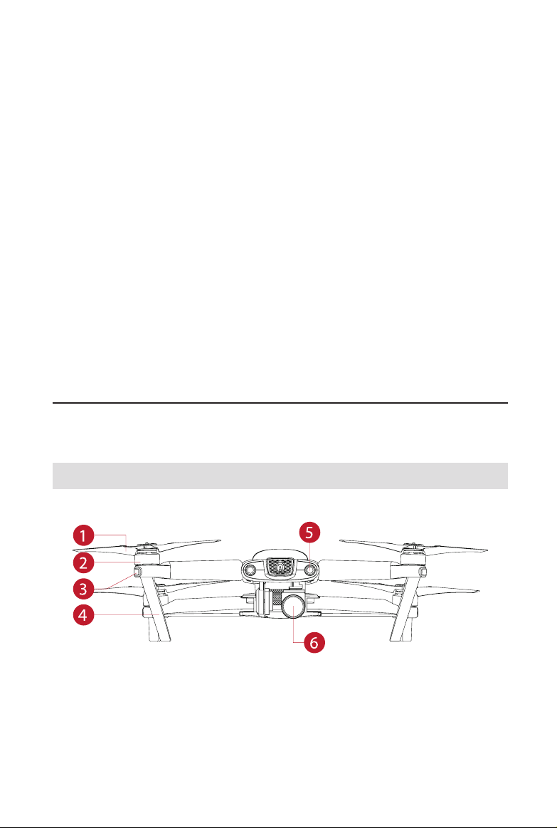
2.1.1 Functionality Description
Front Side
① Propellers ④ Landing Gear
② Motors
⑤ Forward Vision System
3
Page 12
③ Front LED Indicators ⑥ Camera Gimbal
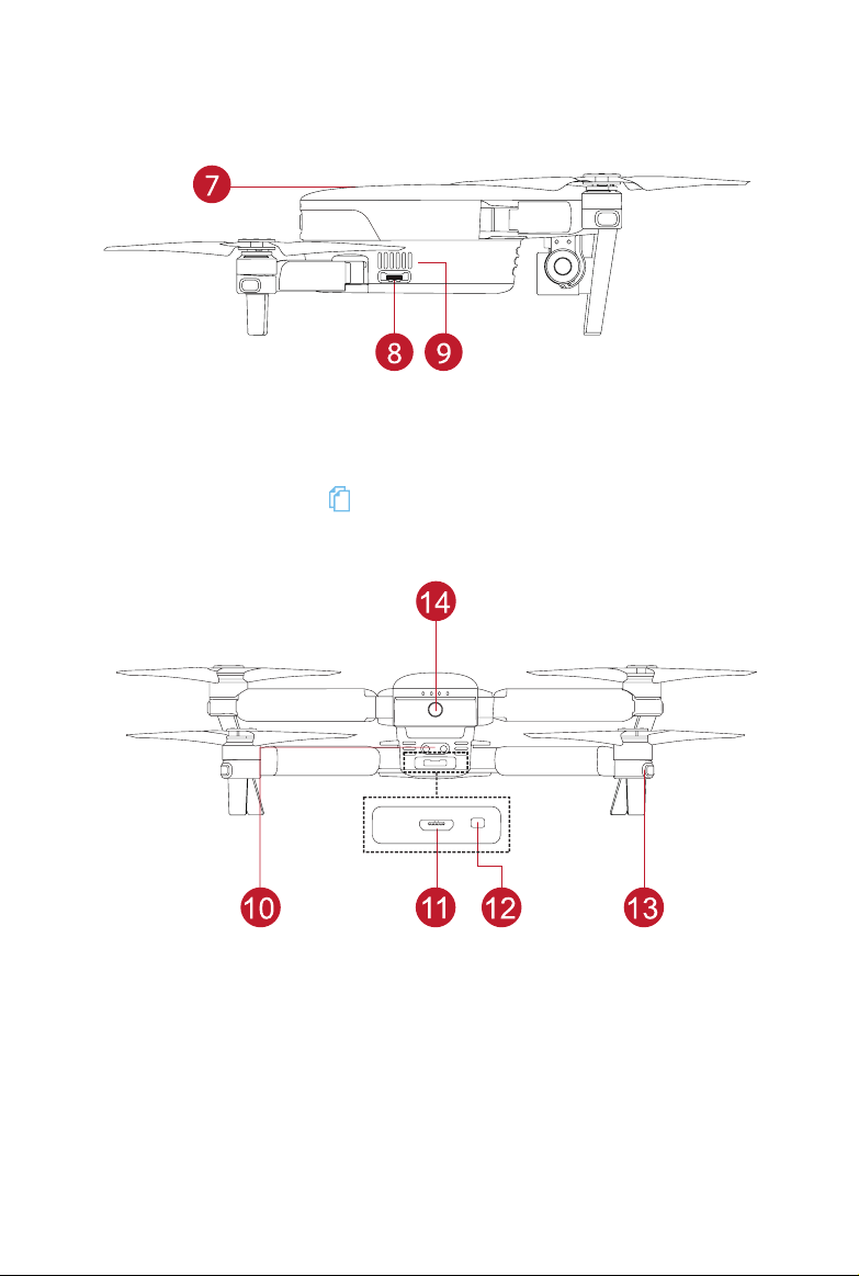
Right Side
⑦ Aircraft Battery ( 6) ⑨ Fan Exhaust
⑧ Micro-SD Card Slot
Rear Side
⑩ Rear Avoidance Sensor ⑬ Rear LED Indicators
⑪ Micro-USB Port
⑫ Remote Control Pairing Button/Pairing Indicator
⑭ Power Button
4
Page 13
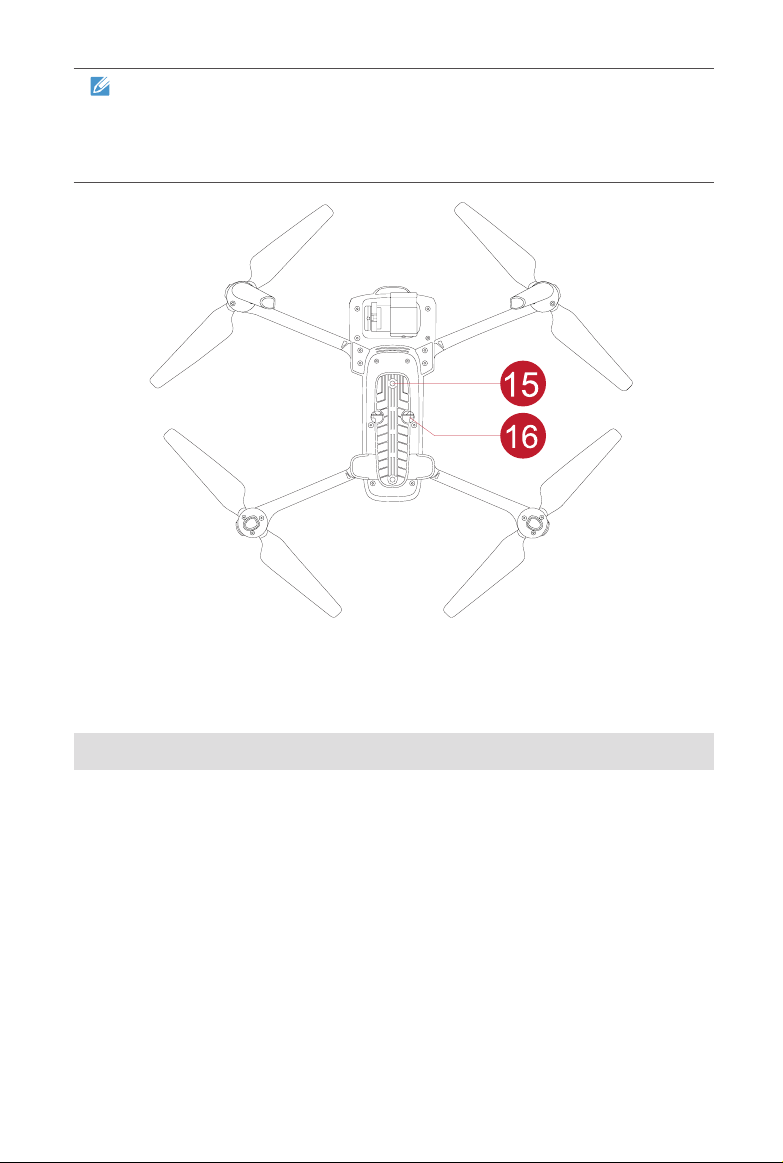
NOTE
There is a protector on the back designed to protect the Micro-USB Port
and Remote Control Pairing Button/Pairing Indicator, remember to
push it back when ying the aircraft.
Bottom Side
⑮ Downward Vision System
⑯ Ultrasonic Sensor
2.1.2 Flight LED Indicators
An LED indicator is located on the end of each aircraft arm. The front LEDs will
light up solid red to help you identify the direction of the EVO’s nose. The rear
LEDs will display the current ight status of the aircraft. Refer to this chart to
conrm the meaning of the different status indicators.
Indicator Key: Color Key:
Solid Light R Red Color
Slow Flashing: Flashes once every two seconds G Green Color
Fast Flashing: Flashes two times per second Y Yellow Color
Double Flashing: Flashes two times then pauses and repeats
Alternate Flashing: Alternate among different colors
Example: “R - Solid Light” Solid Red Light
5
Page 14
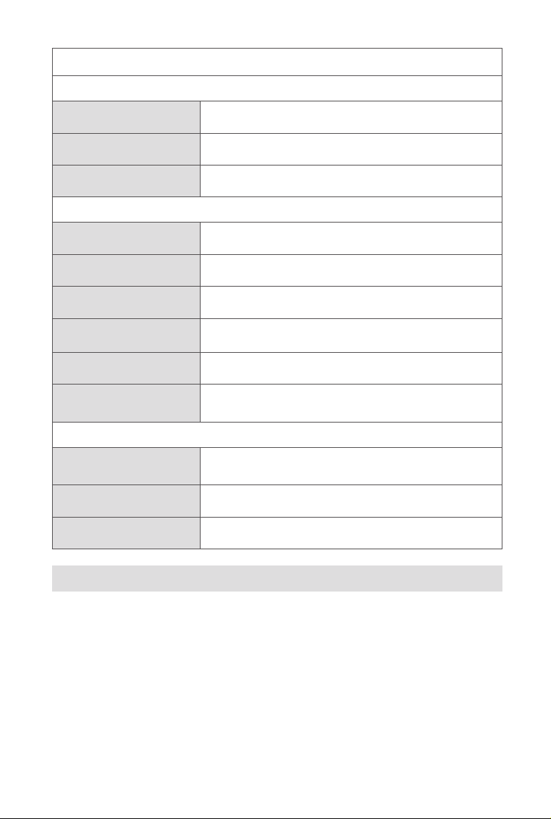
Denitions of Flight LED Indicator Status
Normal Status
RGY - Alternate Flashing System self-test is activated
YG - Alternate Flashing The aircraft is warming up
G - Slow Flashing
The aircraft is in GPS mode
Warning
Y - Slow Flashing The aircraft is in ATTI mode
Y - Fast Flashing No connection between the aircraft and remote control
R - Slow Flashing Low Battery Warning
R - Fast Flashing Critically Low Battery Warning
R - Solid Light Critical problems, IMU error
RY - Alternate Flashing
Abnormal compass, calibration is required /
Magnetometer interference
Compass Calibration
Y - Fast Flashing
G - Solid Light Calibration is successful
R - Solid Light Calibration is failed
Be ready to calibrate the compass / The aircraft is
calibrating
2.1.3 Aircraft Battery
EVO’s custom-designed, rechargeable Li-Po battery with a capacity of 4300mAh
can provide up to 30 minutes of continuous ight with a full charge. It should be
charged exclusively using the supplied charger.
Basic Functions
6
Page 15
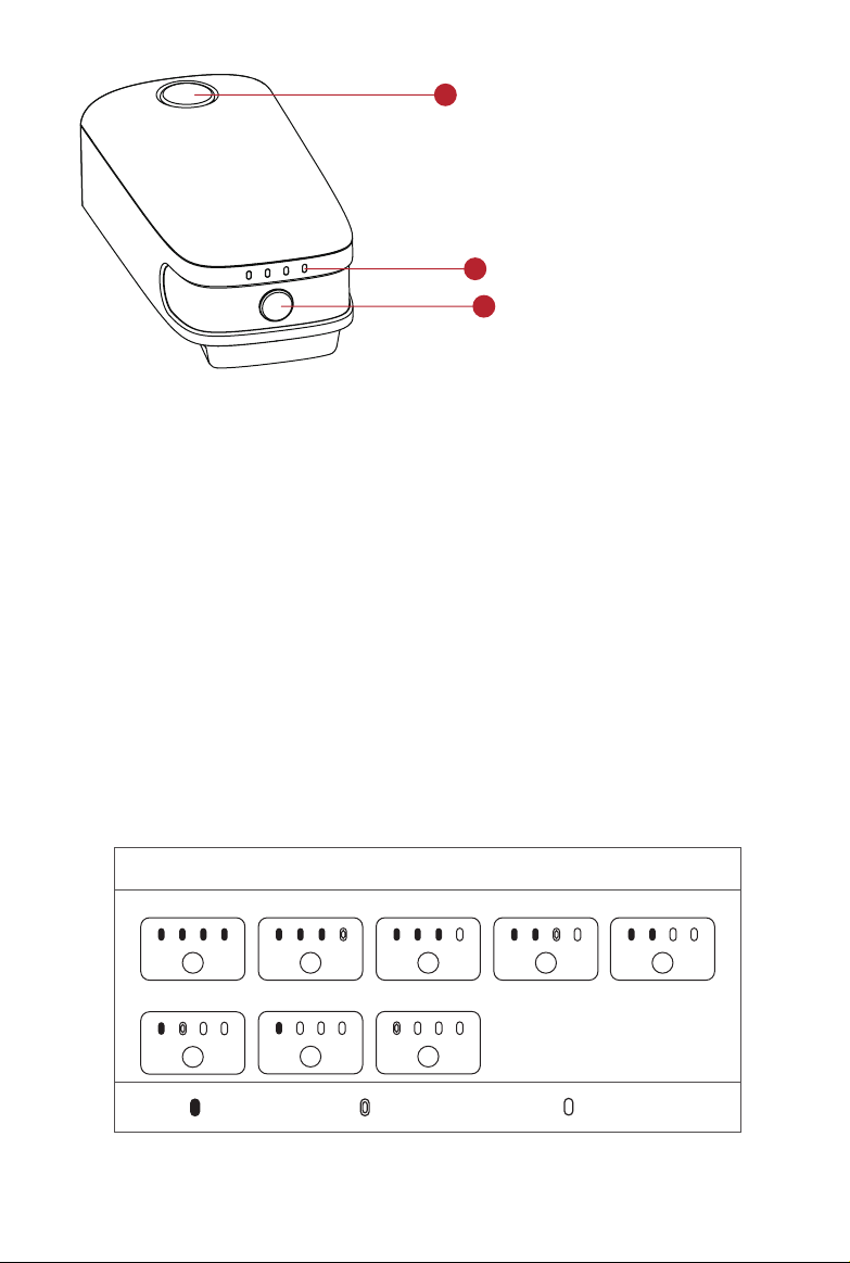
1
Aircraft Battery
① Removal Button
② Capacity Level Indicators
③ Power Button
2
3
Turning On the Battery
Make sure the battery is off before attaching it to the aircraft. After attaching it,
press and hold the Power Button for 3 seconds. The capacity level indicators will
display the current battery level.
Turning Off the Battery
Press and hold the Power Button for 3 seconds to turn off the battery. If the
battery is attached on the aircraft, the LED1 and LED 4 will ash for 5 times to
indicate shutdown. Remove the aircraft battery from the aircraft after turning off
all the Capacity Level Indicators.
Checking the Battery Level
To check the battery level without powering it on, press the Power Button for 1
second, then release it quickly. The LEDs will display the current battery level as
shown below.
Battery Level Indicator Status While Discharging
87.5%~100%
25%~37.5% 12.5%~25% 0%~12.5%
- Solid Green Light - Flashing Green Light - No Lights
75%~87.5% 62.5%~75% 50%~62.5% 37.5%~50%
7
Page 16

Additional Functions
The smart functions listed below will give you a full understanding of the aircraft
battery and how to protect and preserve the battery life.
Storage Self-Discharge Protection: In order to prevent damage, after the
battery has been idle for 6 days and the voltage is higher than 12V, the battery
will discharge automatically to approximately 70% of total power. This is the
default setting, and the discharge process takes 2-3 days. While there’s no
formal indication that the battery is performing a self-discharge cycle, you
may notice a slight warming of the battery, which is normal. The discharge
threshold can be customized using the Autel ExplorerTM app.
Charging Temperature Detection: The normal charging temperature should
be between 10°C (50°F) and 45°C (113°F), the battery will stop charging if the
temperature exceeds this range.
Overcurrent Protection: The battery will stop charging if the charging current
exceeds 8A to prevent severe damage.
Overcharge Protection: Charging will stop automatically when the battery
reaches full charge.
Balance Protection: Balances the voltage of each battery cell to prevent
overcharging or over-discharging.
Over-Discharge Protection: When the battery is not in use, it will
automatically disconnect the power output function once the self-discharge
cycle is completed. This function is disabled during ight.
Short Circuit Protection: The power supply will be cut off in the event that a
short circuit is detected.
Power Saving Mode: After 30 minutes of inactivity, the battery will disconnect
from the power supply and enter power saving mode to retain the energy.
Communication: When in use, the aircraft continuously syncs with the
battery to provide real-time information including voltage, capacity, current,
and temperature.
Ultra-Low Power Consumption Mode: When idle for 7 days with a voltage
lower than 11.7V, the battery will enter this mode in order to conserve power.
It will resume normal function after being connected to the charger.
8
Page 17
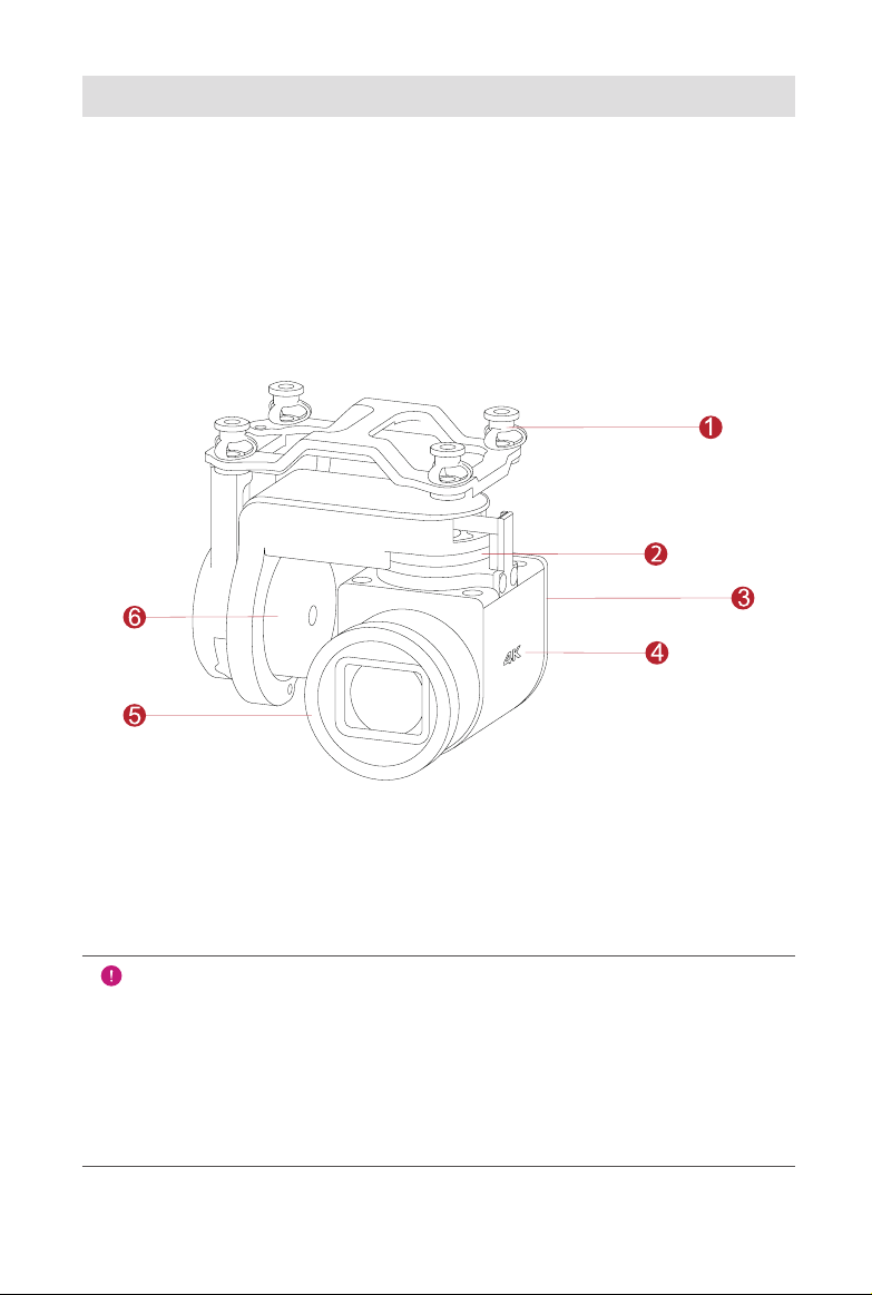
2.1.4 Gimbal & Camera
XI-5A Camera Gimbal
The camera gimbal is engineered to minimize camera vibration and provide
superior stability, with a controllable roll axis range of 0°~90°. The operating
temperature is maintained at -10°C~50°C (14°F~122°F).
When the aircraft is powered up, the gimbal will automatically perform a calibration
test. Use the diagram below to familiarize yourself with all the moving parts of the
gimbal.
① Vibration Absorber ④ Camera
② Yaw Motor
③ Roll Motor ⑥ Pitch Motor
⑤ Filter
IMPORTANT
• The EVO XI-5A Camera Gimbal is held in place with a gimbal holder to
protect the gimbal from the incidental rotation — and to avoid damage
when stored.
• Remember to remove the holder before powering up the aircraft.
Failure to do so may result in damage to the gimbal motors and
circuitry.
9
Page 18
The XI-5A Camera Gimbal has two working modes:
Stabilized Mode: The gimbal’s orientation stays aligned with the aircraft’s
nose, but keeps the horizon even as the aircraft tilts.
FPV Mode: The gimbal is continually synchronized with the aircraft’s
movement — including rotation and tilt — to create a rst-person viewing
experience during the ight.
Camera
EVO’s 4K UHD camera supports a variety of shooting modes, including:
Single Shot
Burst Shooting
AEB
Time-lapse
The camera saves photos in DNG or JPG formats, and records videos in MOV or
MP4 formats. A high-denition live feed from the camera can be displayed on your
remote control’s screen, or with improved image quality on your mobile device
using the mobile app.
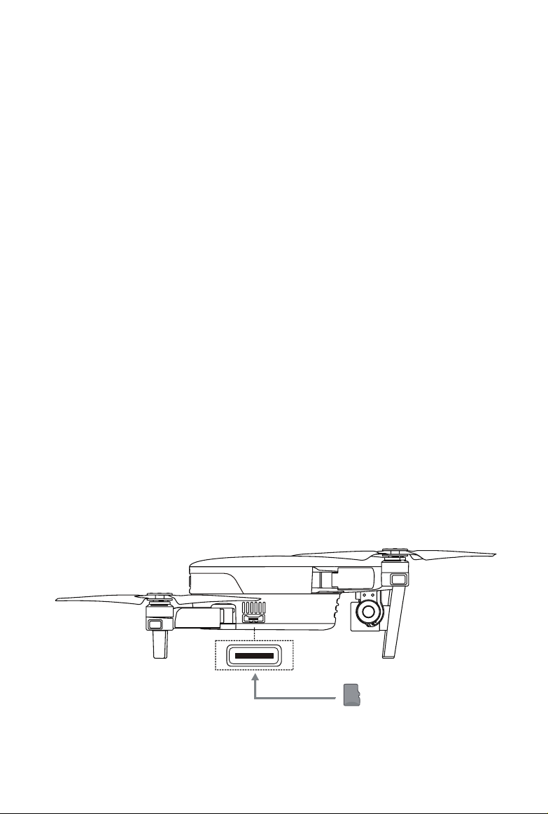
Using a Micro SD Card
Before turning on the aircraft, insert a micro SD card into the port illustrated below.
EVO supports SD card capacity up to 128GB. If you plan to shoot HD video, we
recommend using a Class 10 or UHS-1 micro SD card.
10
Page 19
WARNING
To prevent le loss, always power off the aircraft before removing the
micro SD card.
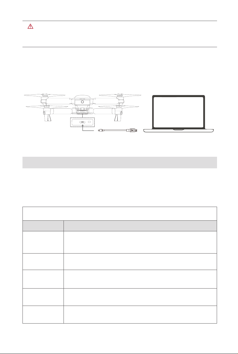
Transferring Files to Your Computer
To transfer photos and videos to your computer, connect it to the aircraft via the
Micro USB Port as shown below.
2.1.5 Built-in Smart Flight System
EVO delivers stable and user-friendly ight control via its built-in Smart Flight
System. The system enables a variety of advanced functions, including Go
Home, Failsafe, and the StarpointTM Positioning System, and operates using
the modules described below.
Smart Flight System Modules
Module Description
IMU
Compass
GNSS Receiver
Barometer
Ultrasonic
Sensors
A 3-axis gyroscope and 3-axis accelerometer measures
acceleration and angular velocity. Automatic IMU calibration is
performed when the aircraft is powered on.
Measures geomagnetic eld and provides heading reference for the
aircraft.
Receives GNSS (GPS/GLONASS) signals to determine the latitude,
longitude, and altitude.
Measures atmospheric pressure to determine the altitude of the
aircraft.
Measures the distance between the aircraft and ground.
11
Page 20
Binocular
Vision System
Enables forward and downward binocular vision.
Rear Avoidance
Sensor
Infrared transmitter/receiver on the rear of the aircraft that scans for
potential obstacles.
Flight Modes
EVO’s 2 ight modes help you pilot the aircraft according to GPS availability and
ying conditions.
Flight Modes
Flight Modes Description
GPS Mode is activated if the aircraft detects proper GNSS signals.
GPS Mode
ATTI Mode
GPS works with the Forward and Downward Vision Systems
to locate and navigate obstacles, provide stable and smooth ight
maneuvers, and enable safety features like Go Home and Failsafe.
ATTI Mode is activated when the GPS signal is weak, and lighting
conditions are insufcient for the vision systems. Obstacle avoidance
features are disabled, and the aircraft uses only its barometer for
controlling altitude.
2.1.6 Smart Flight Features
Go Home
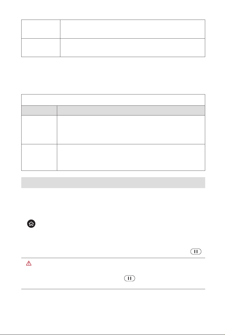
The Go Home function can be enabled when good GPS signal is available. To
manually activate the Go Home process, press and hold the Go Home Button
( ) for 3 seconds on the remote control. Once the aircraft receives this
command, it will return automatically and land at the present home point.
EVO can detect and avoid obstacles on its ight path using Forward Vision
System. The remote control’s function will be disabled while the aircraft returns
to the home point, but you can reactivate it by pressing the Pause Button ( ).
WARNING
If the Forward Vision System is disabled during the Go Home period,
remember to press the Pause Button ( ) on the remote control to exit
the Go Home feature and regain control of the aircraft.
12
Page 21
IMPORTANT
• The default Go Home altitude is 30 meters. If you activate Go Home
when the aircraft is lower than that, it will rise to 30m before returning.
Learn how to adjust the Go Home altitude in the App Manual.
• If the Go Home function is activated within a 10m radius from the home
point, the aircraft will automatically descent and land.
Failsafe
The Failsafe function is designed to help EVO automatically return home or land
on-site when necessary.
Communication Lost
Failsafe will be triggered 3s after the communication between your aircraft and
remote control gets lost.
If GPS is available when activating the Failsafe function, the aircraft will
automatically use the Go Home function. Otherwise, it will land from its current
position. When the remote control signal returns, you can still press the Pause
Button ( ) to regain control of the aircraft.
Low Aircraft Battery Level
Failsafe will also be activated if you meet either of the following low battery
conditions.
A. EVO continually calculates the required battery level for the aircraft to return
to the home point. A notice on the Autel ExplorerTM app will appear when
the battery level reaches the minimum level required for the aircraft to return
to the home point. Failsafe will be activated, and EVO will automatically y
home. Again, you can regain control of the aircraft by pressing the Pause
Button( ) during the Go Home process.
B. When EVO’s battery level reaches the 25% threshold, you’ll receive a Low
Battery Warning and Failsafe will be activated, after which the aircraft will
automatically return home. If you retake control of the aircraft, when the
battery reaches 15%, you’ll receive a Critically Low Battery Warning, and
the aircraft will automatically land in its current position. In the case of an
emergency, you may press the Pause Button( ) to halt the landing and
y it to the nearest possible safe landing site.
13
Page 22

NOTE
• If the aircraft is within 50 horizontal meters from the home point when
your aircraft battery level reaches 25% (Low Battery Warning), the
aircraft will not perform the Go Home procedure.
• If GPS is unavailable when Failsafe is activated at Low Battery
Warning, the aircraft will not execute the Go Home procedure. Instead,
the aircraft will stay in your control and only proceed to land automatically
when the battery reaches 15% (Critically Low Battery Warning).
Landing Features
Landing Protection
When the aircraft arrives above the home point, Landing Protection functionality
will detect the ground conditions below. EVO will land automatically if the ground
is level and at. If not, it will hover at the current location to wait for the next
command.
Accurate Landing
EVO will scan and match the terrain features if Accurate Landing function is
active, it will land as close as possible to the takeoff point once the current terrain
matches the takeoff point terrain.
IMPORTANT
• EVO records the takeoff point as the default home point. Accurate
Landing is available only when the home point has not been refreshed
during the ight.
• Choose an open and well-lit area (such as a lawn) as your takeoff point.
• When Accurate Landing is preparing to land the aircraft, make sure
that conditions at your takeoff point haven’t changed.
NOTE
Landing Protection and Accurate Landing can be enabled using the
app. Instructions for these functions are available in the App Manual.
StarpointTM Positioning System
14
Page 23
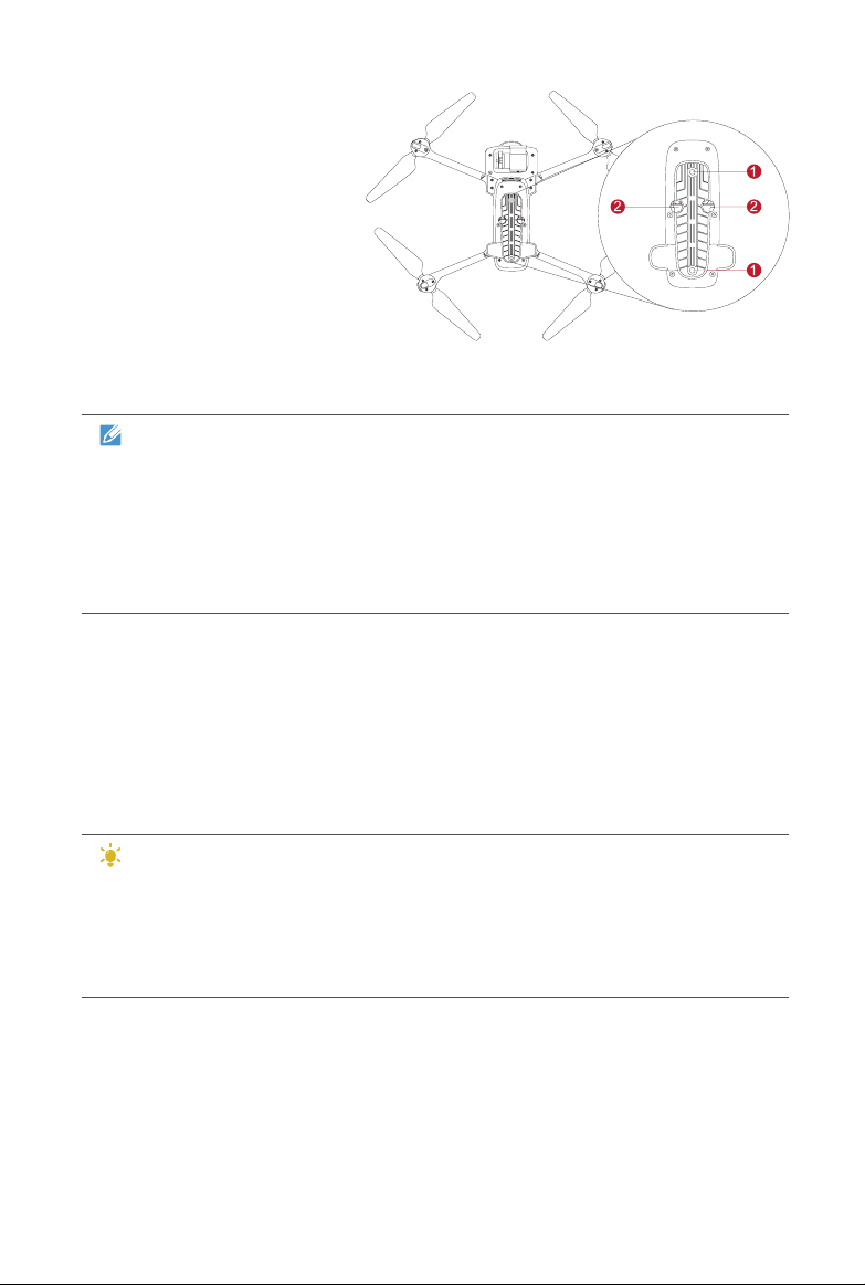
EVO StarpointTM Positioning
System functions through
Binocular Cameras① and
two Ultrasonic Sensors② on
the bottom of the aircraft. The
sensors calculate the current
height of the aircraft using
ultrasound, and the camera
obtains location information
via image analysis. When
ying indoors or in another environment where a GPS signal is unavailable,
StarpointTM Positioning System allows the aircraft to hover in place precisely.
NOTE
• The StarpointTM Positioning System is activated by default when the
aircraft is powered on.
• It works both in GPS and ATTI modes.
• It is only enabled when the aircraft is between 0.5m and 10m above the
surface.
Forward Vision System & Rear Avoidance Sensors
The Forward Vision System on the front of the aircraft uses image data to
calculate the distance between the aircraft and potential obstacles. The system
will halt EVO’s forward progress when an obstacle is detected. Infrared sensors
detect motion and measure any heat being emitted by potential obstacles to the
rear of the aircraft.
TIPS
• Always keep the binocular camera lens clean.
• When the StarpointTM Positioning System is activated, don’t use other
40KHz ultrasonic devices nearby, such as ultrasonic rangenders, fault
detectors, cleaners or welding machines.
15
Page 24
IMPORTANT
The performance of the StarpointTM Positioning System and Forward
Vision System are affected by the brightness and texture of the surface
over which the aircraft is ying. The ultrasonic sensors may not function
accurately above sound-absorbing materials. Because of this, we
recommend that you avoid ying EVO over surfaces that are:
• Monochrome
• Highly reective, such as water
• Extraordinarily dark or bright
• Subject to frequent lighting changes
• Made of closely repeating patterns, such as tiles
• Absorbent of sound waves, such as thick carpet
• In motion, such as roads with heavy trafc
Also, avoid ying at high speeds while at low altitude: We caution against
ying faster than 8 meters per second at a 2-meter height, or over 4m/s at
a 1-meter height.
2.2 Remote Control
EVO has an unobstructed range of up to 7km under optimum conditions. The
remote control supports live video downlink, and functions without a paired mobile
device. The video downlink system and aircraft remote control system operate at
2.4GHz or 900MHz, depending on what you select. The 3.3-inch OLED screen
displays live video feed, battery level, GPS signals, ight speed, and more.
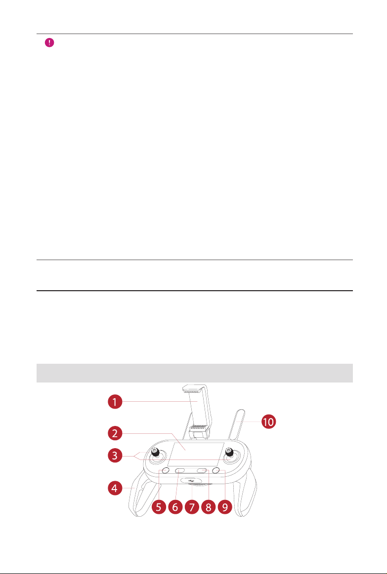
2.2.1 Functionality Description
16
Page 25
① Mobile Device Holder
With a 180° adjustable viewing angle for optimum
visibility
② Flight Information Panel
③ Command Sticks Control the orientation and movement of the aircraft
④ Hand Grips These are foldable to allow for compact storage
⑤ Take-off/Landing Button Commands the aircraft to take off or land
⑥ Power Button
⑦ USB Ports
⑧ Pause Button
⑨ Go Home Button Commands the aircraft to return to the home point
⑩ Antennas
Displays the ight status, warning messages and
real-time live view
Press and hold the button for 3 seconds to turn on/off
the remote control
The two ports can be used for charging or connecting
to your mobile device
Tells the aircraft to pause autonomous ight operations
and hover in place (press it a second time, and
autonomous mode will resume)
Communicate with the aircraft at 2.4GHz or 900MHz
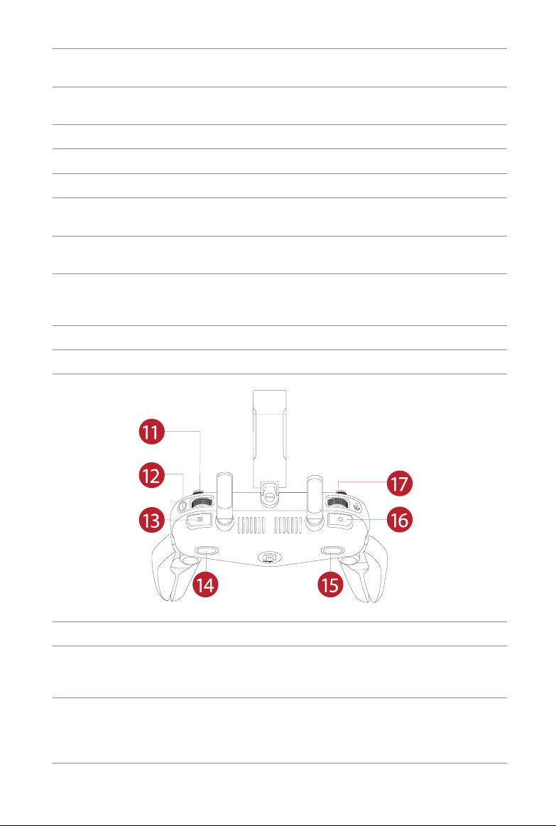
⑪ Screen Navigation Dial Scrolls the OLED screen
⑫ Screen Navigation Button
⑬ Shutter Button
When the mobile device is disconnected, press
this button for one second to enter/exit the Image
Transmission screen on the remote control
Takes photos. When Burst Mode is turned on,
several images will be taken with one press. More
details on this function can be found in the App
Manual
17
Page 26
⑭ Customizable Button A
The function is customized by yourself using the
mobile app
⑮ Customizable Button B
⑯ Record Button
⑰ Gimbal Pitch Dial Controls the pitch angle of the camera gimbal
The function is customized by the user using the
mobile app
Press the button to start or stop recording video
2.2.2 Live View Panel
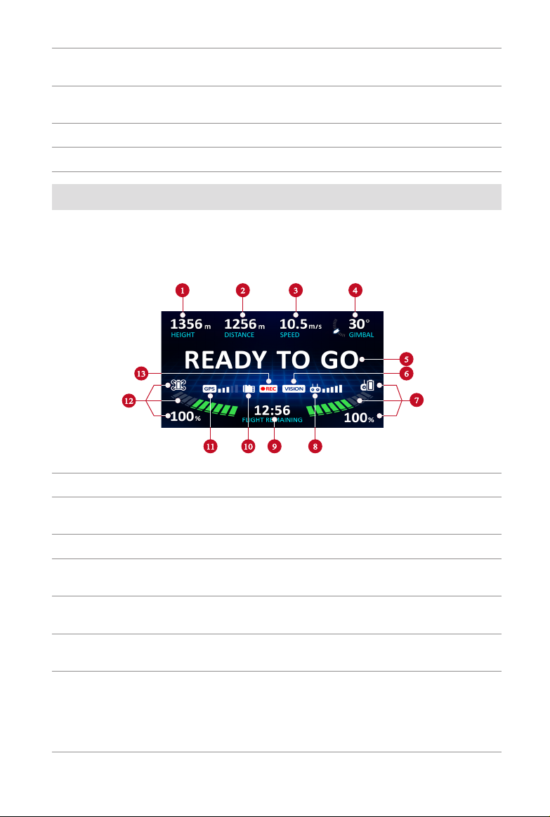
Flight Information Panel
When the video link has been connected, the main interface will appear as below.
① Flight Altitude Aircraft altitude relative to the home point
② Flight Distance
③ Flight Speed Current speed of the aircraft
④ Tilt Angle
⑤ Flight Status Bar
⑥ Vision System
⑦ Remote Control Battery
Horizontal distance between the aircraft and home
point
The camera’s angle tilted by the gimbal (range:
0°~90°)
Displays real-time ight status and current ight
mode
Displays when the Vision Obstacle Avoidance
System is enabled
• Displays the current battery level
• Green bars indicate normal battery (approximately
11%-100%)
• Red bars indicate low battery (approximately 10%)
18
Page 27
⑧ Remote Control Signal Shows the current signal strength
⑨ Remaining Flight Time
⑩ Micro SD Card
⑪ GPS Signal
⑫ Aircraft Battery
⑬ Record Status
Estimates how much longer the aircraft can stay in
the air
Indicates that the Micro SD Card is installed and
available
Indicates the signal strength of nearby GNSS
satellites
• Displays the current battery level
• Green bars indicate normal battery
• Orange bars indicate low battery
• Red bars indicate critically low battery (you can
set the battery level threshold using the Autel
ExplorerTM mobile app)
Indicates if you are currently recording
Image Transmission Mode
Press the Screen Navigation Button on the remote control when you want to
enter the Image Transmission Mode. Then follow these steps:
1. Scroll the Screen Navigation Dial to highlight the different setting options.
2. Press the Screen Navigation Dial instructed on the screen to enter the
related option.
3. Scroll the Screen Navigation Dial again to set different values.
4. Press the Screen Navigation Dial to conrm this value or press the Screen
Navigation Button (DISP) to go back.
5. Press the Shutter Button to take photos.
6. Press the Record Button to start or stop recording videos.
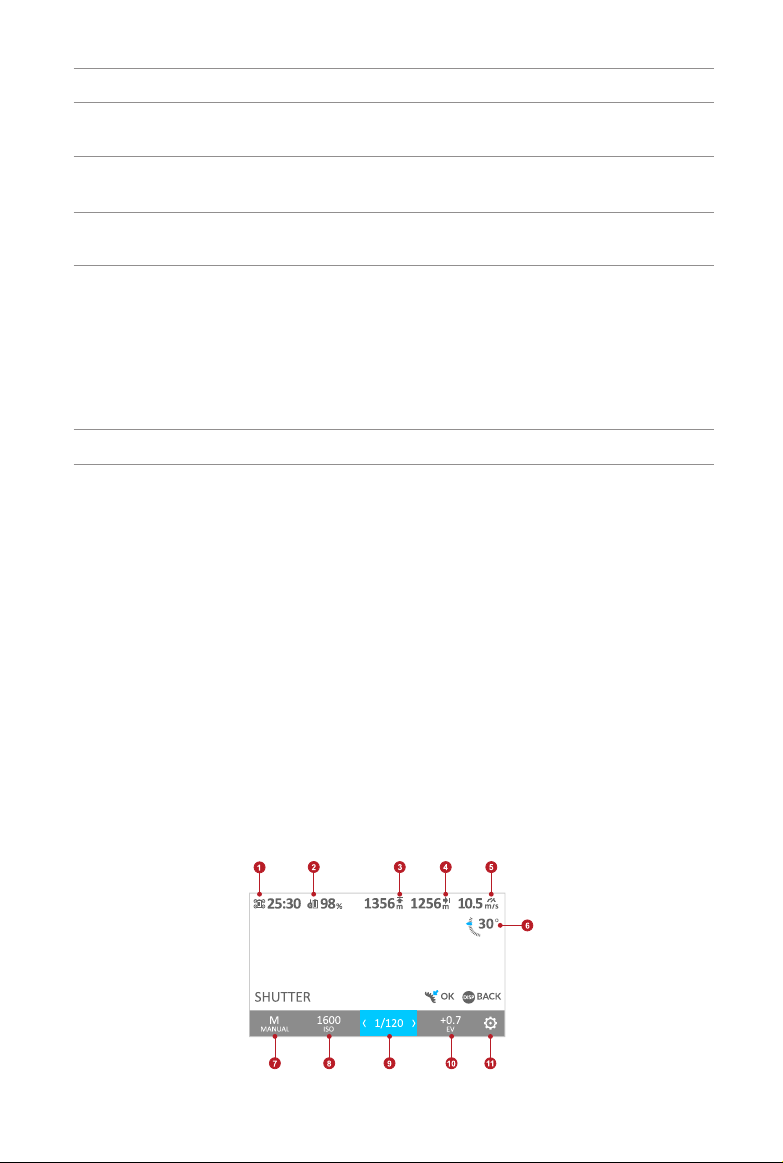
Image Transmission View
19
Page 28

① Remaining Flight Time
② Remote Control Battery Displays the battery level remaining
Estimates how much longer the aircraft can stay in
the air
③ Altitude
④ Distance
⑤ Flight Speed Displays the current speed of the aircraft
⑥ Gimbal Angle
⑦ Exposure Mode
⑧ ISO
⑨ Shutter
⑩ EV
Displays the aircraft altitude relative to the home
point
Displays the horizontal distance between the aircraft
and the home point
The number in the picture indicates the angle of the
gimbal in degrees. The blue arrow will rotate as the
gimbal angle changes
Set your camera to in order to adjust your ISO and
shutter speed, or choose Auto and let the camera do
the work for you
• Manual: The EV setting will be disabled
• Auto: The ISO and shutter speeds will be disabled
This setting adjusts the images sensor to the
sensitivity to light. A lower ISO works on bright sunny
days, and a high ISO is great for low light scenarios
but will increase the noise/grain in the image.
Fast shutter speeds let you capture action in motion;
longer shutter speeds are helpful in low-light scenarios
The Exposure Value (EV) is a combination of both
the ISO and shutter speed, and is used when the
camera is set to Auto. Adjust the EV to brighten or
darken the exposure
⑪ Settings
Press this button to access the Advanced Settings
page
Settings
Basic Instruction
1. Scroll the Screen Navigation Dial to highlight different setting options on the
top of the screen.
2. Press the Screen Navigation Dial instructed on the screen to enter the
related option or press the Screen Navigation Button (DISP) to go back to
the last step.
3. Scroll the Screen Navigation Dial again to set different values.
20
Page 29
4. Press the Screen Navigation Dial to conrm this value or press the Screen
Navigation Button (DISP) to go back to the last step.
Camera Settings
Camera (* =default value)
Photo Mode *Single, Burst (3/*5/7/14), Time Lapse
(2/*5/7/10/20/30/60), AEB (*3/5)
Photo Format *JPG, RAW, JPG+RAW
Video Resolution *4K (3840x2160), 4K+(4096x2160), 2.7K (2720x1530),
1080P (1920x1080), 720P (1280x720)
Video Frame Rate 240FPS, 60FPS, 48FPS, *30FPS, 24FPS
Video Standard *NTSC, PAL
Flight Control Settings
• Turn Novice Mode on/off
• Choose the Speed Limit value
• Adjust the Go-Home Altitude, Altitude Limit, and Distance Limit
NOTE
When Novice Mode is engaged, the aircraft will operate with a xed
maximum Go-Home Altitude (98ft), Speed Limit (11mph), Altitude Limit
(98ft), and Distance Limit (328ft). You can’t enter these limit settings even
press the Screen Navigation Dial.
Remote Control Settings
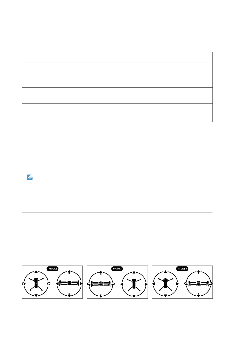
1. Command Stick Mode
Mode 1, Mode 2 and Mode 3 allow you to control the aircraft according to your
preferences, as illustrated below.
21
Page 30
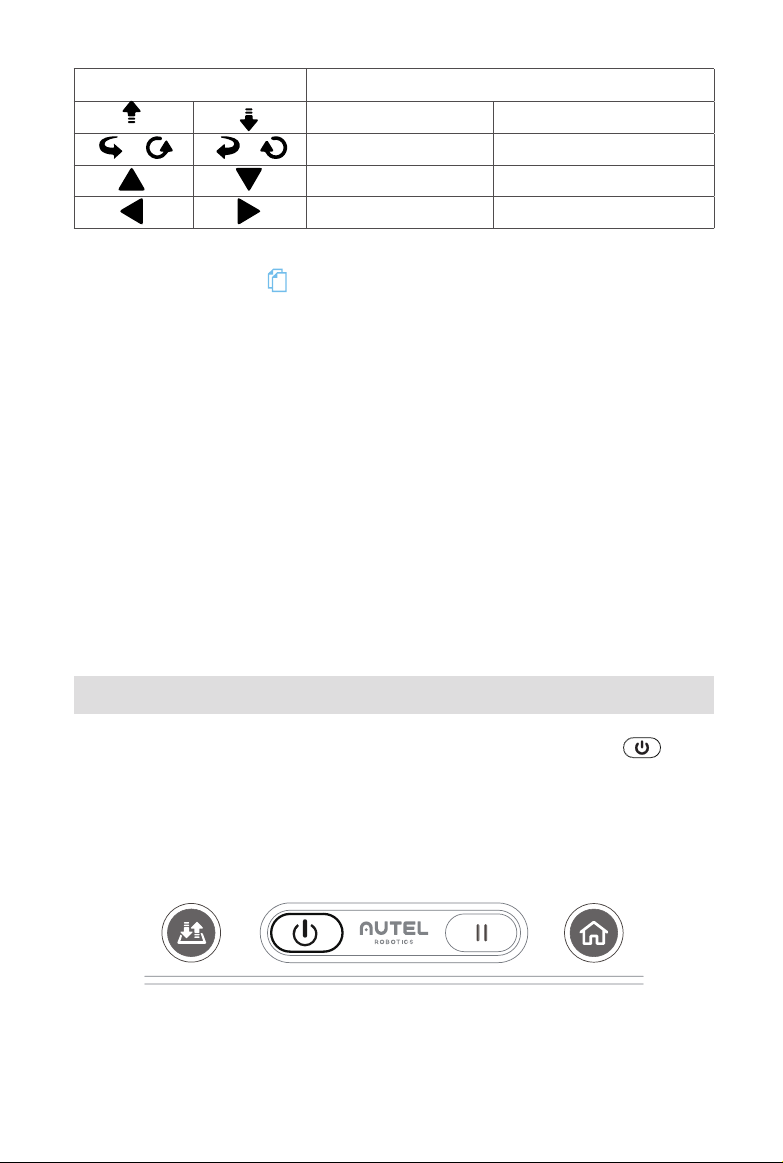
Indicator Icons Aircraft Movement
Ascend Descend
/ / Nose rotates left Nose rotates right
Move forward Move backward
Move left Move right
2. Remote Control Calibration
Refer to Section 3.2.3 ( 27) for detailed calibration instructions.
Vision Settings
Access these settings to turn Visual Obstacle Avoidance on/off and select
Show Radar Map.
General Settings
1. Language: Select the displayed language.
2. Units: Choose the unit of measurement displayed in Flight Control Settings:
Metric (m/s) or Imperial (mph).
3. Gimbal Mode: Choose Stabilized Mode or FPV Mode.
4. Format SD Card: Use this to ensure that your SD card is in an acceptable
format.
5. Reset Camera: Use this to restore all the camera settings to default.
2.2.3 Indicator Lights
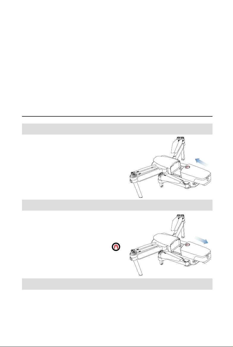
A single LED indicator is located under the remote’s Power Button ( ).
●
◎
○
Solid Light
Flashing Light
No Lights
Example: “R-●” SOLID RED light
R
G
Y
22
Red Light
Green Light
Yellow Light
Page 31

G-●
G-◎ Indicates that the remote control is charging while powered on
Y-● Low battery warning
R-● Indicates that the remote control is charging while powered off
R-◎ Firmware is upgrading
Indicates sufcient battery level when the remote control is in use, or
that a full charge has been reached when charging
○
The remote control is powered off or has reached full charged while
powered off
2.2.4 Remote Controller Buzzer Alerts
The table below describes the various buzzer alerts and their corresponding
meanings.
Remote Controller Buzzer Alerts
Aircraft Low Battery Warning
(about 25%)
Aircraft Critically Low Battery Warning
(about 15%)
Remote Control Low Battery Warning
(10%)
Remote Control Critically Low Battery
Warning (5%)
Aircraft & Remote Control
Communication Lost
Video Link Disconnected 3 quick beeps in 1 second
1 quick beep every second (lasts for 5s),
with 2 remote control vibrations
5 quick beeps every second (last for 5s),
with 5 remote control vibrations
1 quick beep every second (lasts for 5s)
5 quick beeps every second (last for 3s),
with two remote control vibrations
2 quick beeps every second (last for 5s),
with 1 remote control vibration
Compass Interference 3 beeps with 3 remote control vibrations
Standby Notication 3 beeps every 15 minutes of inactivity
23
Page 32
Chapter 3
Preight Preparation
EVO features a user-friendly design and comes fully assembled out of the box. In
order to ensure safe drone operation, please read and understand the instructions
and warnings below before your rst ight.
3.1 Battery Preparation
3.1.1 Aircraft Battery Installation
1. Power off the battery before installing it.
2. Insert the battery into the battery
compartment as shown on the right.
3. The battery will rmly click in place.
3.1.2 Aircraft Battery Removal
1. Power off the aircraft battery before
removal.
2. Press and hold the top button ( )
located on the battery and pull it out
slowly.
3.1.3 Charging
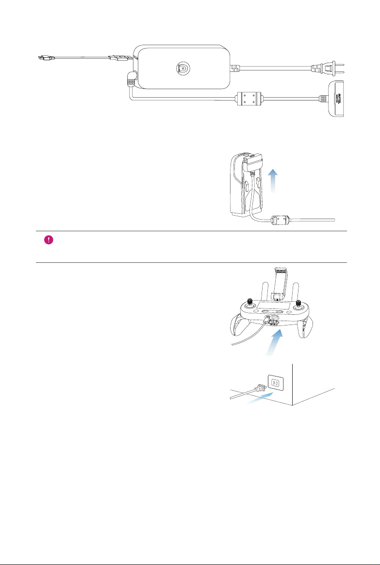
The aircraft battery and remote control can be charged simultaneously using the
supplied charger. There are two connectors attached to the charger’s adapter
block. As shown below, the xed one goes with the aircraft battery, and the USB
cable is used to charge the remote control.
24
Page 33
Charging the aircraft and remote control
1. Aircraft Battery: Plug the charging
connector into the battery’s charge
port, as shown on the right.
IMPORTANT
Make sure to fully charge the aircraft battery before ight.
2. Remote Control: Open the protector
on the USB port and plug in the
provided charging cable.
3. Charger: Plug it into a power outlet.
Capacity Level Indicators: The LEDs on the aircraft battery will illuminate
from left to right to indicate the current battery level during the charging cycle,
and will turn off when the battery is fully charged.
25
Page 34
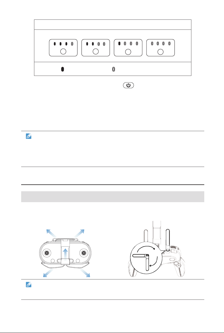
Capacity Level Status During Charging
75%~100% 50%~75% 25%~50%
- Solid Green Light - Flashing Green Light
0%~25%
During Charging: The Power Button ( ) on the remote control will be
green when it is powered on, or red when it’s powered off. You can monitor the
charging process on the Flight Information Panel. You’ll hear 2 beeps when
charging is complete.
4. When charging is completed, disconnect the charger and the aircraft battery/
remote control.
NOTE
• Always y with a fully charged aircraft and remote control battery.
• It takes approximately 80 minutes to fully charge the aircraft battery, and
180 minutes to charge the remote control.
3.2 Remote Control Preparation
3.2.1 Unfolding the Remote Control
The remote control is folded in the package. Unfold the Mobile Device Holder,
Antennas, and Hand Grips carefully before use to prevent damage and to
ensure optimal range of ight.
270°
NOTE
The antennas can be rotated 270 degrees as shown in the diagram.
26
Page 35
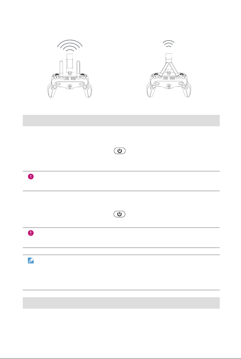
Positioning the Antennas
Vertically align the antennas in parallel with each other, as shown below.
Strong Weak
3.2.2 Powering Up/Off the Remote Control
Powering Up
Press and hold the Power Button ( ) for 2 seconds until you hear a short
beep. The Flight Information Panel will light up and cycle through an initial
verication test.
IMPORTANT
Always turn on the remote control rst before powering up the aircraft.
Powering Off
Press and hold the Power Button ( ) for 2 seconds until you hear a short
beep.
IMPORTANT
Always power off the aircraft before turning off the remote control.
NOTE
When not connected to the aircraft, the remote control makes an alert
sound after 15 minutes of inactivity, and turns off automatically after 18
minutes.
3.2.3 Remote Control Calibration
If the Command Sticks are abnormal (For example, if the remote control falls on
the ground accidentally, or the aircraft’s ight direction does not match control
27
Page 36
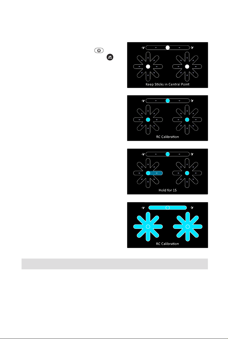
inputs), it is recommended to calibrate the remote control. You can calibrate your
remote control according to the following steps, or by using the mobile app (Refer
to the App Manual for more information).
1. Turn off the remote control. Press and
hold the Power Button ( ) and
Take-off/Landing Button ( )
simultaneously until the screen
appears as shown on the right. The
four crossed bars represent the left
and right Command Sticks. The
horizontal bar at the top is the Gimbal
Pitch Dial.
2. Release both Command Sticks
and the Gimbal Pitch Dial naturally
to the central position. The three
middle rounds on the remote control
calibration screen will be highlighted
successively.
3. Push and hold the Command Sticks
in every possible direction until you
hear a beep each time. Then turn
the Gimbal Pitch Dial clockwise
until you hear a beep, then again
counterclockwise.
4. Calibration is complete when all the
bars on the screen are highlighted.
3.2.4 Pairing the Aircraft & Remote Control
The remote control and aircraft come paired out of the box. When you need to
pair your EVO and remote control again — such as after pressing the Remote
Control Pairing Button on the aircraft — follow these steps:
28
Page 37
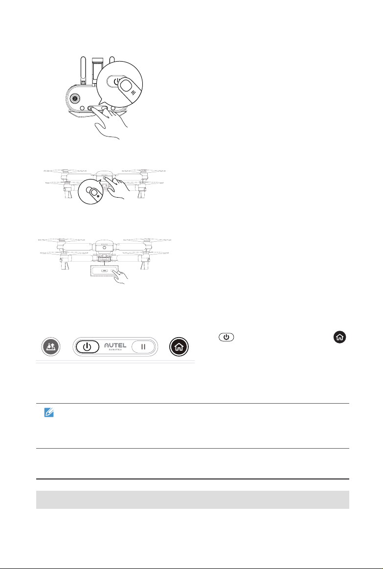
1. Turn off the remote control.
2. Remove the gimbal guard rst
then turn on the aircraft.
3. Press and hold the Remote
Control Pairing Button for about
3 seconds. The Pairing Indicator
will ash quickly, indicating the
aircraft is ready to pair with the
remote control.
4. Press and hold the Power Button
( ) and Go Home Button ( )
simultaneously for 2 seconds until
“Autel” appears on the Flight
Information Panel. The Pairing
Indicator will turn off once your
pairing is successful.
NOTE
You may also use the app to pair the aircraft and remote control. The
instructions are available in the App Manual.
3.3 Aircraft Preparation
3.3.1 Unfolding the Aircraft
29
Page 38
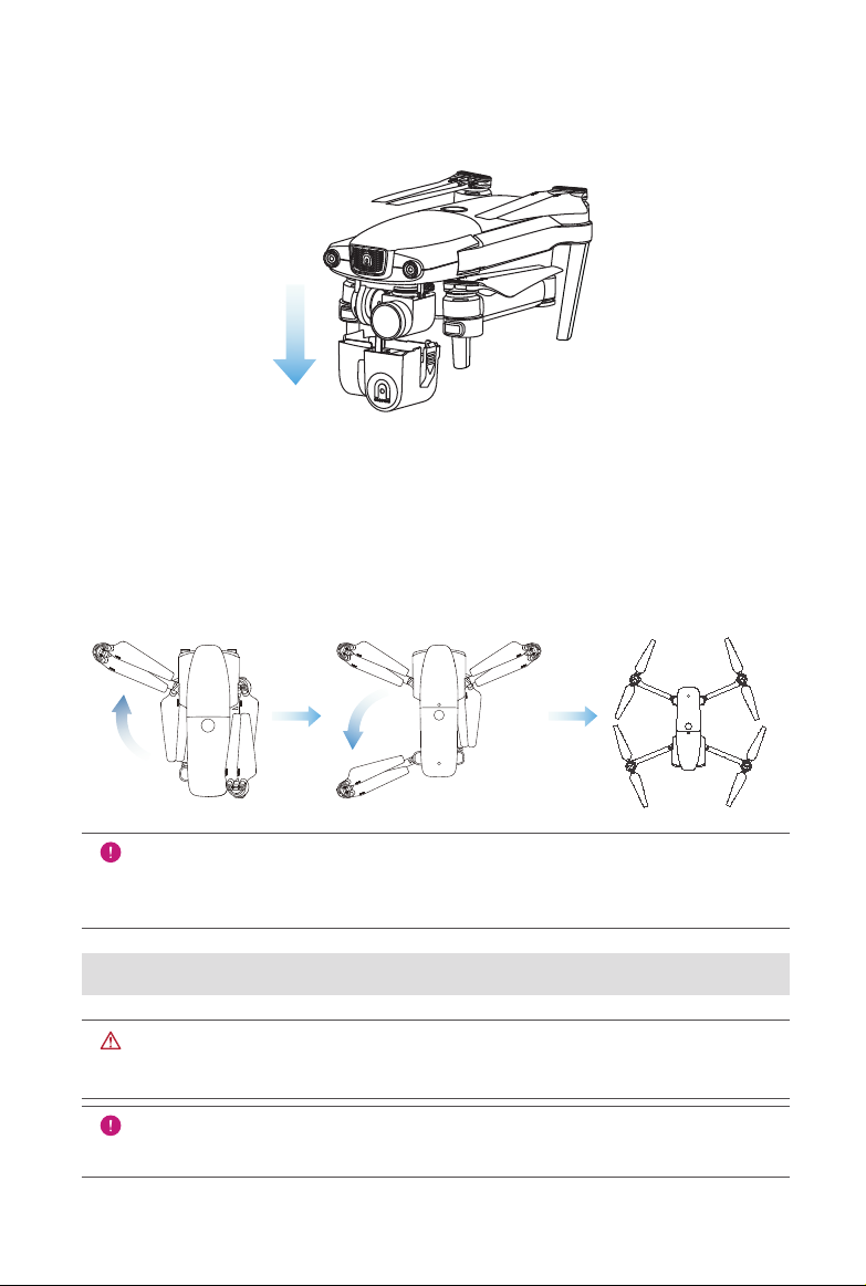
Removing & Reinstalling the Gimbal Holder
Always remove the gimbal holder before powering up the aircraft. Slowly pull out
the attached gimbal holder, as shown in the diagram.
After using the aircraft, reinstall the gimbal holder in order to protect the gimbal
from damage.
Unfolding the Arms & Propellers
Always unfold the arms and propellers before powering on the aircraft.
Unfold the front arms rst, then the rear ones.
IMPORTANT
Power off the aircraft before folding it. Fold in the rear arms and propellers
rst, then the front.
3.3.2 Propellers Installation
WARNING
Power off the aircraft before attaching or detaching propellers.
IMPORTANT
Be sure to wear protective gloves when assembling or detaching propellers.
30
Page 39
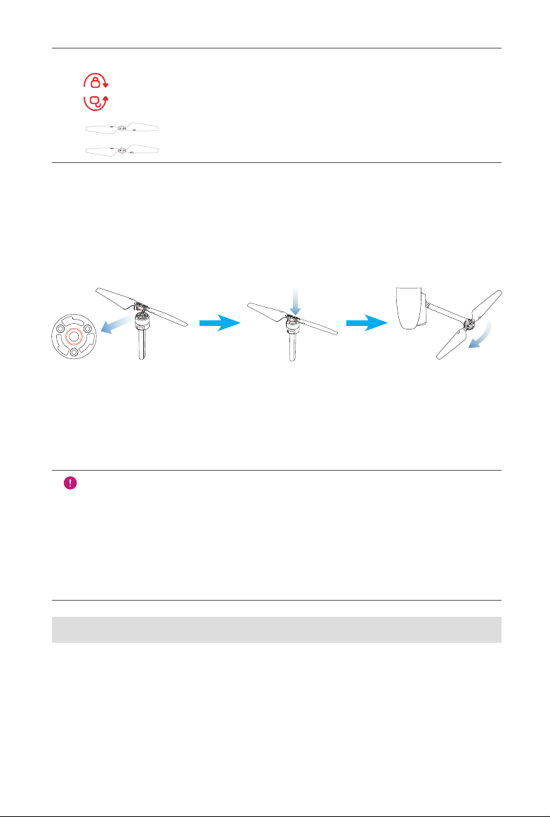
Legends
Lock Direction: Fasten the propeller by rotating it as indicated.
Unlock Direction: Unfasten the propeller by rotating it as indicated.
Black-coded propeller > Pairs with > Black-coded motor
Orange-coded propeller > Pairs with > Orange-coded motor
Attaching the Propellers
1. Verify the aircraft is powered off.
2. Locate and match the propeller to each motor.
3. Press each propeller down rmly and rotate in the lock direction to securely
attach the propeller.
Detaching the Propellers
1. Power off the aircraft.
2. Press each propeller down rmly and rotate in the unlock direction to detach
the propeller.
IMPORTANT
• Before ight, double-check and make sure every propeller is securely
attached.
• Never y with broken or damaged propellers.
• Don’t touch the propellers or motors while they’re spinning.
• Always remove the propellers before testing the motors.
3.3.3 Compass Calibration
The compass is calibrated out of the box, typically making user-calibration
unnecessary. If you experience compass error warnings, or the aircraft’s ight
direction does not match control inputs, or you y the aircraft at a very long
distance from your calibration position, follow the steps below to calibrate it.
31
Page 40
WARNING
The compass is very sensitive to electromagnetic interference causing
compass error and poor ight. If you nd the compass abnormal after
calibration, move the aircraft to another location and try again.
When calibrating the compass, remember to:
1. Set up in an open outdoor area.
2. Stay clear of all sources of magnetic interference, like magnetite or the steel
reinforcement found in concrete. Proximity to large structures may also result
in reduced calibration.
3. Stay well clear of underground and overhead power lines.
4. Remove all ferromagnetic materials (e.g., keys, magnetic jewelry).
5. Remove electronic devices that might interfere with the calibration (e.g.,
mobile devices, the remote control).
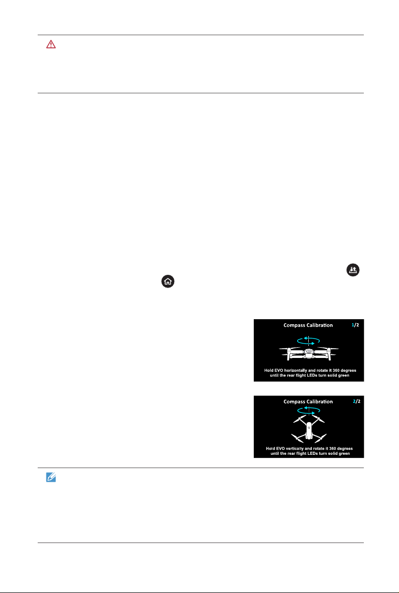
Calibration Procedure
1. Start the calibration process by pressing the Take-off/Landing Button ( )
and Go Home Button ( ) on the remote control simultaneously for 3
seconds. The Rear LED Indicators on the aircraft will ash yellow when you
initiate the calibration process.
2. Hold the aircraft horizontally and rotate it until
the Rear LED Indicators on the aircraft turn
solid green, indicating this step has been
completed successfully.
3. Hold the aircraft vertically with the nose facing
downward and rotate it until the Rear LED
Indicators on the aircraft turn solid green,
indicating that the calibration is successful.
NOTE
• If the calibration is unsuccessful, the Rear LED Indicators on the aircraft
will illuminate solid red. In this case, repeat the above steps.
• You can also calibrate the compass using the Autel ExplorerTM app.
Find out how in the App Manual.
32
Page 41

Chapter 4
Flight Operations
4.1 Preight Checklist
Follow these steps to carry out a full preight checkup:
• Fully charge the EVO aircraft battery, remote control, and your mobile device
• Remove the gimbal holder
• Make sure the propellers are in proper condition and are correctly attached
• Position the antennas on the remote control so as to get the best possible
transmission quality
• Pair the aircraft and remote control (and your mobile device, if you’re using it)
• Ensure that the rmware has been updated to the latest version
• Make sure you are familiar with the ight controls
• Double-check that your ight area is open and unobstructed
• Check the weather, including air temperature and wind speed
• Check the EVO camera lens and sensors and clean them as needed
4.2 Remote Control & Flight Operations
There are three Command Stick Modes available for the aircraft: Mode 1, Mode
2 and Mode 3. Each one controls the aircraft differently. The diagrams below
employ Mode 2, which is the default. You can change the mode by following to
the instructions in the App Manual.
Basic Flight
1. Place the aircraft in an open, stand at least 5 meters clear of the rear of the
aircraft.
2. Turn on the remote control.
3. Turn on the aircraft and wait for the Rear LED Indicators to ash green
slowly.
33
Page 42
4. Start the motors and take off using the remote control.
5. Pilot the aircraft carefully.
6. Land the aircraft, then shut down the motors.
4.2.1 Motor Start & Aircraft Takeoff
NOTE
The aircraft will not take off if the battery level is 15% or lower.
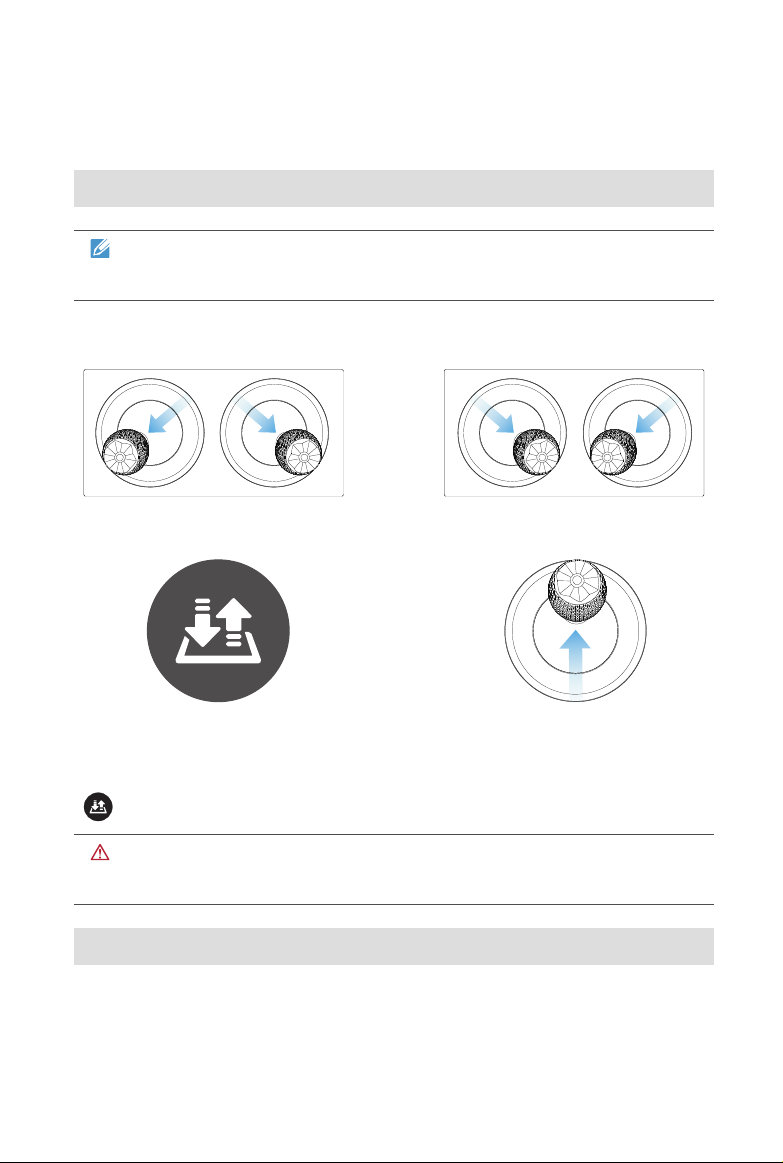
Start the motors by holding both Command Sticks in position for 2 seconds:
OR
With the motors spinning, choose either of the following takeoff commands:
OR
Hold the Takeoff/Landing
Button for 2s
If you command the aircraft to take off pressing the Take-off/Landing Button
( ), the aircraft will automatically ascend to a height of roughly 1.5 meters.
Push the Left Command
Stick slowly upward (Mode 2)
WARNING
The motors are hot after operation. Please handle with care.
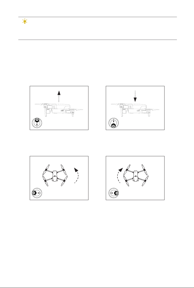
4.2.2 Command Stick Controls (Mode 2)
34
Page 43
TIPS
For novices, we recommend moving the Command Sticks slowly while
you get comfortable ying the aircraft.
Left Command Stick
Ascend/Descend
Command the aircraft to ascend by pushing the stick up, and descend by pressing
it down.
Left Side Veiw
Ascend
Left Stick
Left Side Veiw
Descend
Left Stick
Rotate Left/Rotate Right
Control the heading of the aircraft by pushing the stick left or right.
Top View
Left Stick
Top View
Left Stick
Right Command Stick
Forward/Backward
Command the aircraft to move forward or backward by pushing the stick up or
down.
35
Page 44
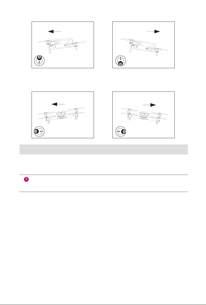
Left Side Veiw
Forward
Left Side Veiw
Backward
Nose Rear
Right Stick
Nose Rear
Right Stick
Move Left/Move Right
Tell the aircraft to move left or right by pushing the stick left or right.
Rear Veiw
Left
Right Stick
Rear Veiw
Right
Right Stick
4.2.3 Landing & Motor Shutdown
EVO can be landed manually, automatically, or passively. Follow the steps below
to land the aircraft by each of these means.
IMPORTANT
Always land gently on a at, level, open surface.
Manual Landing
You can land the aircraft manually whenever and wherever you want using the
Command Sticks on the remote control.
Landing the aircraft manually
1. Find the desired position for landing the aircraft.
2. Release the Command Sticks when the aircraft reaches the target position
to let it hover.
3. Push the Left Command Stick downwards slowly to land the aircraft.
Shutting down the motors
36
Page 45
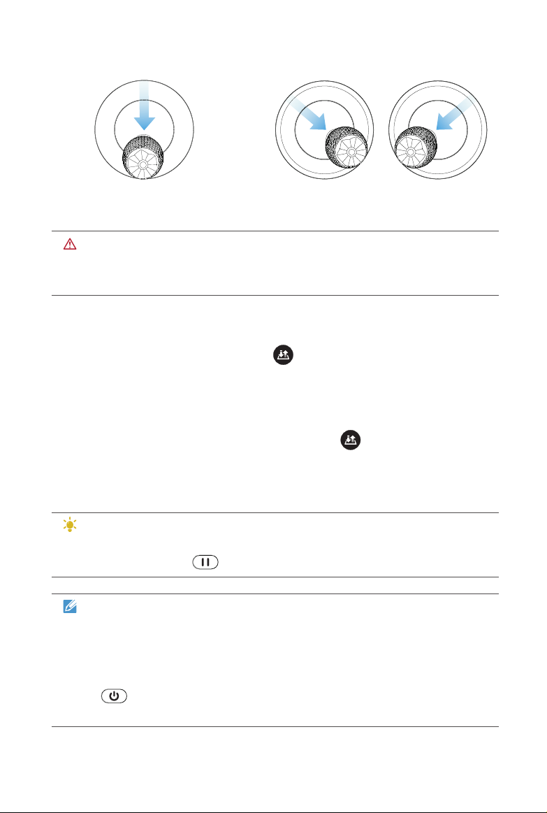
Choose one of the following methods to shut down the motors after EVO reaches
the ground:
OR
Push the Left Command Stick
to the bottom and hold for 2s
Hold both Command Sticks
toe-in for 2s
WARNING
The toe-in action will always shut down the motors even if EVO is in midair.
Pay extra cautious and use this feature only in an emergency.
Automatic Landing
Press the Take-off/Landing Button ( ) on the remote control to land the
aircraft automatically from its current hover position.
1. Navigate the aircraft to the target landing position.
2. Release the Command Sticks and let the aircraft hover.
3. Press and hold the Take-off/Landing Button ( ) for 2 seconds until you
hear a beep from the remote control.
4. The aircraft will descend, land and shut off its motors automatically. During
descent, you can adjust the aircraft position using the Right Command Stick.
TIPS
During the automatic descent process, you can regain control by pressing
the Pause Button ( ) on the remote control.
NOTE
• Automatic landing is also available in ATTI mode, but you should monitor
the attitude of the aircraft, as it may drift.
• When the Low Battery Warning (25%) is displayed — at which the
EVO rear LEDs will ash red and the remote control Power Button
( ) will turn solid yellow — return to a safe landing point as soon as
possible.
37
Page 46

Passive Landing
Whenever either of the following conditions is met, Failsafe will be triggered and
the aircraft will automatically land on-site.
The Low Battery Warning is activated in non-GPS environment.
The Critically Low Battery Warning is activated.
38
Page 47

Chapter 5
Maintenance & Service
5.1 Firmware Upgrade
To optimize the performance of your EVO, Autel Robotics will provide rmware
updates on an ongoing basis. You can download the latest rmware in one
package from our ofcial website. When a rmware update is available, you will
receive a prompted on the Autel ExplorerTM app after connecting it to the aircraft.
IMPORTANT
Before updating, make sure:
• The motors are not spinning.
• The battery levels of both EVO and the remote control are not less than
25%.
• There’s adequate space to store the rmware le on your camera’s
micro SD card.
Downloading & upgrading the rmware
1. Download the all-in-one rmware upgrade package (with a .zip le extension)
from Autel Robotics’ ofcial website: www.autelrobotics.com.
2. Insert the SD card into your computer and extract the downloaded le (into
a .bin le extension) into your SD card. Then remove your SD card from the
computer.
3. Insert the SD card into the aircraft to start the upgrade process automatically.
You can check the real-time upgrade status displayed on the Flight
Information Panel.
4. Turn on the remote control and aircraft.
5. Reboot the remote control and aircraft before use.
39
Page 48

IMPORTANT
• The upgrade takes about 15 minutes. Don’t turn off EVO or the remote
control, or remove your SD card from the camera during the process.
Do not start the motors.
• After upgrading, the remote control may be disconnected from the
aircraft. If you need to pair them again, see Section 3.2.4: Aircraft &
Remote Control Preparation ( 28 ).
5.2 Troubleshooting Tips
Q1. If EVO indicates a failure during self-check (Rear LED Indicators will
turn solid red):
• Hardware problems detected, contact the Customer Service:
• www.autelrobotics.com/contact-us/
Q2. If the motors fail to start up:
• Verify the remote control and the aircraft are paired
• Check the remote control to make sure it’s calibrated correctly
• Verify the aircraft battery level
• Make sure the compass is calibrated correctly
• Make sure GPS is available (if Novice Mode is active)
Q3. If takeoff fails after starting motors:
• Double-check that EVO is not in a known no-y zone
• Make sure the aircraft is on a at, level surface
Q4. If ight time is preemptively reduced:
• The most common cause of reduced ight time is a low temperature in the
operating environment or increased takeoff weight
Q5. If EVO does not respond to the remote control during the pairing
process:
• Make sure there are no metal objects, mobile devices or other remote controls
nearby
Q6. If Video Link fails or disconnects frequently:
• Double-check that both EVO and the remote control are free from sources of
magnetic or signal interference
Q7. If the camera is powered off during while recording video:
40
Page 49

• Keep the micro SD card inside the camera. Restart the camera and wait until
the video les are recovered to their fullest possible extent
Q8. If the video link is lost when EVO is out of sight:
• Activate Go Home to have the aircraft automatically return to the landing point
5.3 Storage & Maintenance
To ensure optimum performance of the product, we suggest you read and follow
the maintenance instructions in this section carefully.
• Store EVO, the battery and the remote control in an environment that’s clean,
dry, cool and ventilated.
• Keep EVO out of sunlight when not in use.
• Dry your hands before operating the drone.
• Use a soft cloth with alcohol or a mild window cleaner to clean the lens of the
camera, instead of any rough cleansers, detergent or chemicals.
• Ensure that the battery charger does not come in contact with other conductive
materials.
• Avoid dropping your devices especially on a hard surface. Check it in details
after any crash or impact. Contact our Customer Support team if you encounter
any issues: www.autelrobotics.com/contact-us/
• Exclusively use accessories such as battery chargers authorized by Autel
Robotics. Failure to do so may void warranty coverage.
5.4 Warranty
Autel Robotics (the Company) warrants to the original retail purchaser of this
product, that should this product or any part thereof during normal consumer
usage and conditions, be proven defective in material or workmanship that results
in product failure within the valid warranty period from the date of purchase, such
defect(s) will be repaired, or replaced (with new or refurbished parts or products)
at the Company’s option, with Proof of Purchase, without charge for parts or labor
directly related to the defect(s). Some states do not allow limitation on how long
an implied warranty lasts, so the above limitations may not apply to you.
The Company shall not be liable for any incidental or consequential damages
arising from the use, misuse, or mounting of the device. The extent of Autel
Robotics’ liability under this warranty is limited to the repair and replacement
provided above and, in no event, shall its liability exceed the purchase price paid
by purchaser for the product. Visit www.autelrobotics.com for details of the limited
periods warranted for the different parts of this product.
41
Page 50

This warranty does not apply to:
• Batteries that cycle-charged for more than 200 times;
• Products subjected to abnormal use or environmental conditions, accident,
mishandling, neglect, unauthorized alteration, misuse, improper installation or
repair, or improper storage;
• Products with signs of tampering or altering of the serial number label,
waterproof mark, etc.;
• Damage resulting from connection to, or use of any accessory or other product
not approved or authorized by the Company;
• Defects in appearance, cosmetic, decorative or structural items such as
framing and non-operative parts.
• Products damaged from external causes including but not limited to re,
water, dirt, sand, battery leakage, blown fuse, theft or improper usage of any
electrical source.
5.5 Customer Service
This section contains information regarding technical support, repair service, and
application for replacements or optional parts.
5.5.1 Technical Support
If you have any questions or concerns regarding our products, contact us by:
• Telephone: (844) 692-8835 (U.S.A.)
• Email: [email protected]
• In person: Local distributors or agents
5.5.2 Repair Service
If you need to return your device for repair, please ll out and submit a repair
service form on www.autelrobotics.com/warranty/ or contact our Customer
Support Team at (844) 692-8835. You’ll need to provide the following information:
• Name
• Email address
• Mailing address
• Telephone number
• Product name
42
Page 51

• A complete description of the problem, with photo attachments
• For warranty repairs: proof of purchase
• For non-warranty repairs: Preferred method of payment
Autel Robotics’ support team will review your application within 72 hours after
receiving it. After a preliminary evaluation of the problem, our Customer Support
Team will contact you promptly.
43
Page 52

Chapter 6
Appendix
6.1 Regulatory Compliance & Flight
Restricted Area
6.1.1 Compliance & Advisory
FCC Warning Message
Any Changes or modications not expressly approved by the party responsible
for compliance could void the user’s authority to operate the equipment.
This device complies with part 15 of the FCC Rules. Operation is subject to the
following two conditions: (1) This device may not cause harmful interference, and
(2) this device must accept any interference received, including interference that
may cause undesired operation.
FCC Radiation Exposure Statement
For EVO Series / EVO
This equipment complies with FCC radiation exposure limits set forth for an
uncontrolled environment. This equipment should be installed and operated with
minimum distance 20cm between the radiator & your body. This transmitter must
not be co-located or operating in conjunction with any other antenna or transmitter.
For EVO Series with model EF7, SAR tests are conducted using standard operating
positions accepted by the FCC/ISEDC with the device. When used, please keep the
distance with a minimum of 10mm from the body.
Note: This equipment has been tested and found to comply with the limits for
a Class B digital device, pursuant to part 15 of the FCC Rules. These limits
are designed to provide reasonable protection against harmful interference in
a residential installation. This equipment generates uses and can radiate radio
frequency energy and, if not installed and used in accordance with the instructions,
may cause harmful interference to radio communications. However, there is
no guarantee that interference will not occur in a particular installation. If this
equipment does cause harmful interference to radio or television reception, which
can be determined by turning the equipment off and on, the user is encouraged to
try to correct the interference by one or more of the following measures:
44
Page 53

—Reorient or relocate the receiving antenna.
—Increase the separation between the equipment and receiver.
—Connect the equipment into an outlet on a circuit different from that to which the
receiver is connected.
—Consult the dealer or an experienced radio/TV technician for help.
ISEDC RSS Warning
This device complies with ISEDC licence-exempt RSS standard (s). Operation is
subject to the following two conditions: (1) this device may not cause interference,
and (2) this device must accept any interference,including interference that may
cause undesired operation of the device.
Le présent appareil est conforme aux CNR d’Industrie Canada applicables aux
appareils radio exempts de licence.
L’exploitation est autorisée aux deux conditions suivantes:
(1) l’appareil ne doit pas produire de brouillage, et
(2) l’utilisateur de l’appareil doit accepter tout brouillage radioélectrique subi,
même si le brouillage est susceptible d’en compromettre le fonctionnement.
ISEDC Radiation Exposure Statement
For EVO Series / EVO
This equipment complies with ISEDC RF radiation exposure limits set forth for an
uncontrolled environment. This transmitter must not be co-located or operating
in conjunction with any other antenna or transmitter. This equipment should be
installed and operated with minimum distance 20cm between the radiator & your
body.
For EVO Series with model EF7, SAR tests are conducted using standard operating
positions accepted by the FCC/ISEDC with the device. When used, please keep the
distance with a minimum of 10mm from the body.
Any changes or modications not expressly approved by the party responsible for
compliance could void the user’s authority to operate the equipment.
6.1.2 Flight Restricted Area Illustration
The EVO system automatically recognizes the Flight Restricted Area, in which
ights are limited by default. This feature guarantees pilots’ safe and legal
operations of the product. The ight restricted areas are divided into 2 protection
categories.
Flight restrictions are enforced only within countries which require manufacturer
restrictions by law. As of this writing, China is the only nation that requires
manufacturers to impose ight restrictions.
45
Page 54
NOTE
The pilot is responsible for ensuring they are following all ight rules and
regulations in the areas they y.
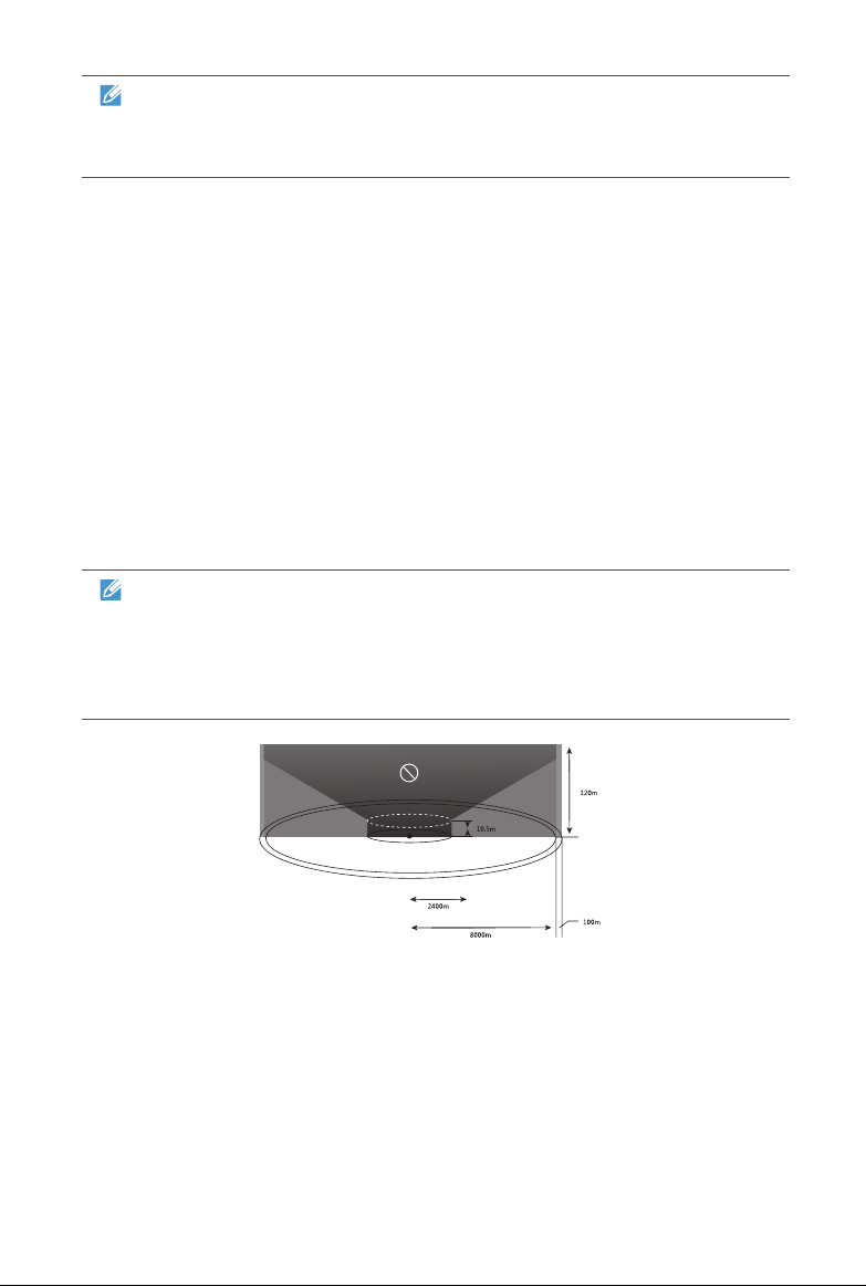
Category I: Major airports & ight areas where drones operate at low altitudes
• Take-off Restricted Zones (No-Fly Zones)
These areas are set within 2.4km (based on country-imposed rules) around the
midway point of specied locations.
• Altitude Restricted Zones
In these areas, the aircraft is only allowed to y within limited altitudes. Depending
on the government-imposed rules, from 8km to 2.4km around the location’s
midway point, the ight altitude decreases progressively from 120m to 10.5m.
• Warning Zones
Once the aircraft enters a region within 8.1 km from the central point of the airport,
the app will prompt a warning message.
NOTE
The aircraft will land automatically when entering any Take-off Restricted
Zones. If the aircraft enters any Altitude Restricted Zones, its maximum
allowable altitude will be reduced accordingly. Pay particular attention to
the warning messages displayed on your app.
Category II: Sensitive areas & institutes such as military sites & border lines
between nations
• Take-off Restricted Zones (No-Fly Zones)
These areas are set within 1km of the center of the specied locations where
takeoff and ight are prohibited.
• Warning Zone
Once the aircraft enters a region within 2km from the center of the Warning Zone
46
Page 55
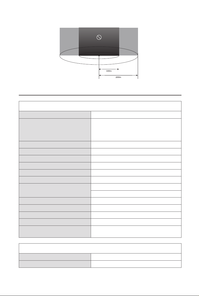
site, the app will display a warning message.
6.2 Specications
Aircraft Specications
Max. Take-off Weight
Hover Precision GPS+ Ultrasonic+IMU:
Max. Yaw Rate 200 dps
Max. Inclination Angle 35 deg
Max. Ascent/Descent Speed Ascent: 5m/s Descent: 3m/s
Max. Horizontal Speed 20 m/s
Diagonal Wheelbase 338 mm
Propeller Size 8.3 inches
Video Link Frequency
Receiver Frequency 2.4GHz~2.4835GHz 902MHz~928MHz
Flight Modes GPS Mode, ATTI Mode
Operating Environment Temperature 0°C~40°C (32°F~104°F)
Storage Temperature -10°C~40°C (14°F~104°F)
Weight
(Battery & Propellers included)
1000g
Horizontal: ±1.5m, Vertical: ±0.2m;
Vision+IMU: Horizontal: ±0.1m, Vertical: ±0.1m
2.4GHz~2.4835GHz
902MHz~928MHz
863 g
Aircraft Battery Specications
Battery Type Lithium-Polymer
Capacity 4300 mAh
47
Page 56

Battery Voltage 11.4 V
Charging Environment Temperature 10°C~45°C (50°F~113°F)
Discharging Environment
Temperature
Storage Temperature & Humidity
Flight Time 30 mins
-20°C~60°C (-4°F~140°F)
Temp: -10°C~40°C (14°F~104°F)
Humidity: 65±20%RH
Camera Gimbal Specications
Operating Current 150mA@12V (Non-video Mode)
Input Voltage 12 V
Operating Temperature -10°C~50°C(14°F~122°F)
Weight 67.5g (Camera incl.)
Dimensions (Damping Device excl.) 42m x 49mm x 45mm
Control Accuracy Pitch: ±0.015° Roll: ±0.015° Yaw: ±0.015°
Max. Angular Velocity Pitch: ±200°/S Yaw: ±200°/S
Controllable Range Pitch: 0°~90° Yaw: ±50°
Camera Specications
Operating Environment Temperature 0°C~40°C (32°F~104°F)
Single shot
Still Photography Modes
Video Recording Modes Normal
Max. Field of View 94°
Supported SD Card Types Micro-SD card
Lense Diameter 25mm
Camera Bit Rate 100M
Storage capacity 4GB-128GB
File Formats
Burst shooting
Auto Exposure Bracketing (AEB)
Time-lapse
FAT32/exFAT
Photo: JPG/DNG
Video: MOV/MP4
48
Page 57

Remote Control Specications
OLED Screen Nits 330
Max. Operating Time 3.8 hours
RF Receiver Operating
Frequency
Video Link Frequency
Operating Temperature 0°C~40°C (32°F~104°F)
Storage Temperature
Max. Control and Video
Transmission Distance
Transmission Power (EIRP) FCC: <=26 dBm CE: <=20 dBm
Operating Current/Voltage 2A @ 3.6V
Battery 6700mAH
Power Consumption 7.2W
Weight (battery included) 370g
2.4GHz~2.4835GHz 902MHz~928MHz
2.4GHz~2.4835GHz
902MHz~928MHz
1 year: -20°C~25°C(-4°F~77°F)
3 months: -20°C~45°C(-4°F~113°F)
7km
49
Page 58

 Loading...