

Page 1

Only using the MV500-2 information par
for the certification
User Manual
Page 2
Trademarks
Autel®, MaxiCheck®, MaxiDAS®, MaxiDiag®, MaxiRecorder®, MaxiScan®,
MaxiSys® and MaxiTPMS® are trademarks of Autel Intelligent Technology
Corp., Ltd., registered in China, the United States and other countries. All
other marks are trademarks or registered trademarks of their respective
holders.
Copyright Information
No part of this manual may be reproduced, stored in a retrieval system or
transmitted, in any form or by any means, electronic, mechanical,
photocopying, recording, or otherwise, without the prior written permission of
Autel.
Disclaimer of Warranties and Limitation of Liabilities
All information, specifications and illustrations in this manual are based on
the latest information available at the time of printing.
Autel reserves the right to make changes at any time without notice. While
information of this manual has been carefully checked for accuracy, no
guarantee is given to the completeness and correctness of the contents,
including but not limited to the product specifications, functions, and
illustrations.
Autel will not be liable for any direct damages or for any special, incidental,
or indirect damages or for any economic consequential damages (including
lost profits).
IMPORTANT
Before operating or maintaining this unit, please read this manual carefully,
paying extra attention to the safety warnings and precautions.
For Services and Support
http://pro.autel.com
www.autel.com
1-855-288-3587/1-855-AUTELUS (North America)
0086-755-86147779 (China)
Support@autel.com
For technical assistance in all other markets, please contact your local selling
agent.
i
Page 3

Safety Instructions
To prevent personal injury or damage to vehicles and/or the scan tool, read
this instruction manual first and observe the following safety precautions at a
minimum whenever working on a vehicle.
Work Area Safety
Always perform automotive testing in a safe environment.
Keep your work area clean and well lit. Cluttered benches and dark areas
may cause accidents.
Keep clothing, hair, hands, tools, test equipment, etc. away from all
moving or hot engine parts.
Operate the tool in a well-ventilated work area.
Do not operate the tool in explosive atmospheres, such as in the
presence of flammable liquids, gases, or heavy dust.
Keep a fire extinguisher suitable for gasoline/chemical/electrical fires
nearby.
Do not use the tool around corrosive chemicals which can ruin the photo
quality.
Keep bystanders, children and visitors away while operating the tool.
Keep the tools dry, clean, free from oil, water and grease. Use a mild
detergent on a clean cloth to clean the outside of the tool when
necessary.
Electrical Safety
Avoid body contact with earthed or grounded surfaces such as pipes,
radiators, ranges and refrigerators.
Do not expose the tool to rain or wet conditions. Water entering the tool
will increase electric risk.
Do not abuse the cord. Never use the cord for carrying, pulling, or
unplugging the tool. Keep cord away from heat, oil, sharp edges or
moving parts.
ii
Page 4

If operating the tool in a damp location is unavoidable, use a ground fault
circuit interrupter (GFCI) to protect supply.
Personal Safety
Do not use the tool while tired or under the influence of drugs, alcohol,
or medications. A moment of interruption can result in serious personal
injury.
Do not over-reach. Keep proper footing and balance at all times. Proper
footing and balance enables better control of the tool in unexpected
situations.
Always wear safety eye protection that meets ANSI standards.
Do not wear loose clothing or jewelry. Keep your hair, clothing, and
gloves away from moving parts. Loose clothes, jewelry, or long hair can
be caught in moving parts.
Do not place the tool on any unstable cart or surface. The tool may fall
causing serious injury to a person or serious damage to the tool itself.
Never spill liquid on the display units. Liquid increases the risk of electric
shock and damage to the tool.
Do not use the tool for personal or medical use in any way.
The product is not shock-resistant. Do not use it as a hammer or drop it.
iii
Page 5
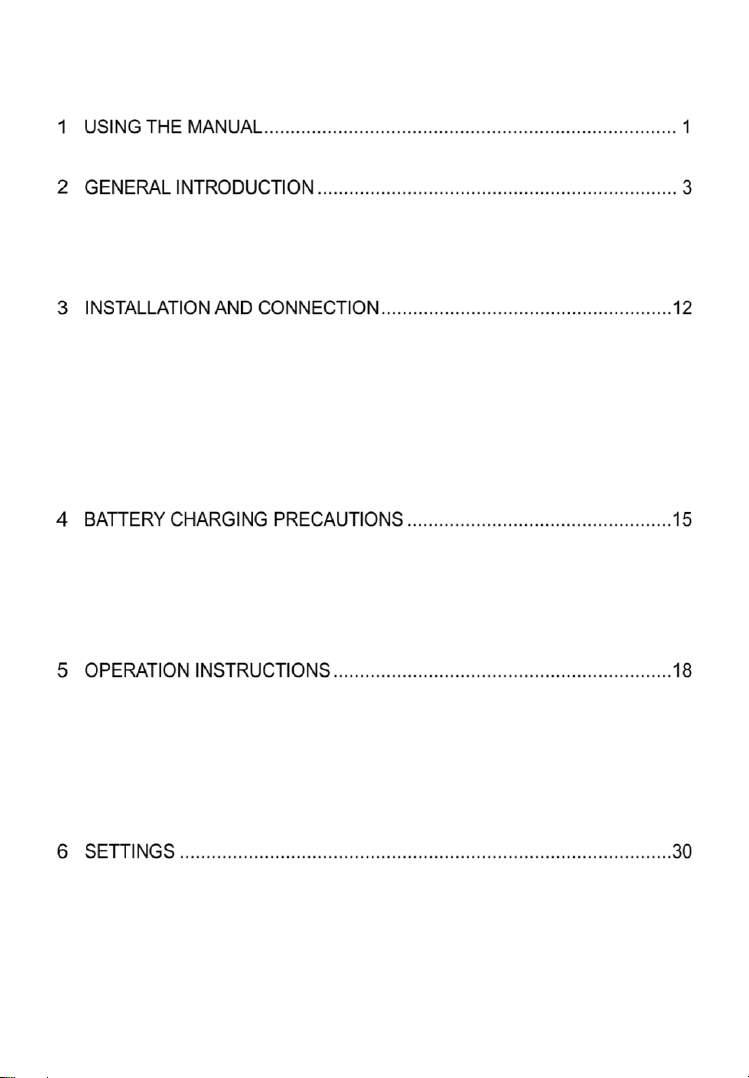
Contents
CONVENTIONS ......................................................................................................1
MAXIVIDEO MV500-1 DISPLAY TABLET
MV500-2 HANDLE, CABLE AND IMAGER HEADS
ACCESSORIES INCLUDED ............................................................................11
THE DISPLAY TABLET AND HANDLE CONNECTION ................................................ 12
THE IMAGER HEADS AND CABLE INSTALLATION .................................................... 12
ACCESSORIES INSTALLATION .............................................................................. 13
MICRO SD CARD INSTALLATION .......................................................................... 13
MINI USB CABLE CONNECTION .......................................................................... 14
HDMI CABLE CONNECTION ................................................................................ 14
BATTERY CHARGING SAFETY .............................................................................. 15
BATTERY AND CHARGER SPECIFICATIONS ........................................................... 15
CHARGER INSPECTION ........................................................................................ 16
BATTERY CHARGING PROCEDURES ..................................................................... 17
NAVIGATION ....................................................................................................... 18
BASIC OPERATION .............................................................................................. 21
OPERATION PRECAUTIONS.................................................................................. 25
TOOL INSPECTION............................................................................................... 27
TOOL AND WORK AREA SET-UP .......................................................................... 28
................................
................................
............................
.............................
3
7
WI-FI ................................................................................................................. 30
COLOR MODE ..................................................................................................... 32
DATE AND TIME .................................................................................................. 33
iv
Page 6

SCREEN BRIGHTNESS ......................................................................................... 34
SOUND ............................................................................................................... 34
LANGUAGE ......................................................................................................... 35
STORAGE LOCATION ........................................................................................... 36
SCHEDULED POWER-OFF .................................................................................... 37
SERIAL NUMBER ................................................................................................. 38
FORMAT ............................................................................................................. 38
RESTORE FACTORY SETTINGS ............................................................................ 39
VERSION ............................................................................................................ 40
UPDATE ............................................................................................................. 41
LIMITED ONE YEAR WARRANTY........................................................................... 48
SERVICE INFORMATION ....................................................................................... 49
v
Page 7

Using the Manual
This manual contains device usage instructions.
Some illustrations shown in this manual may contain modules and optional
equipment that are not included on your system. Contact your sales
representative for availability of other modules and optional tools or
accessories.
Conventions
The following conventions are used.
Bold Text
Bold emphasis is used to highlight selectable items such as buttons and
menu options.
Example:
Tap OK.
Terminology
The term “select” means highlighting a button or menu item and tapping it to
confirm the selection.
Notes and Important Messages
The following messages are used.
Notes
A NOTE provides helpful information such as additional explanations, tips,
and comments.
1
Page 8

Important
IMPORTANT indicates a situation which, if not avoided, may result in damage
to the test equipment or vehicle.
Hyperlinks
Hyperlinks or links that take you to other related articles, procedures, and
illustrations are available in electronic documents. Blue colored text indicates
a selectable hyperlink.
Procedures
An arrow icon indicates a procedure.
Example:
To adjust the sound
1. Tap the Settings icon on the live image screen.
2. Tap the Sound option on the column.
3. Slide the Sound icon left or right on the sound indicator bar for
different volume. The righter the icon is, the louder the sound would
be.
4. Tap Save on the top right corner to confirm and return to Settings
menu.
Illustrations
Illustrations used in this manual are samples, the actual testing screen may
vary for each vehicle being tested. Observe the menu titles and on-screen
instructions to make correct option selection.
2
Page 9

General Introduction
MaxiVideo is Autel’s most advanced digital inspection camera to date.
Its revolutionary tablet design supports wireless image transmission of up to
30 meters between the MaxiVideo MV500-1 display tablet and inspection scope.
Along with its dual-camera cable, MaxiVideo gives technicians the
to work either individually or collaboratively during inspection to
best results.
This manual describes the construction and operation of the device and how
it works to examine difficult-to-reach areas.
MaxiVideo MV500-1 Display Tablet
Functional Description
freedom
produce
Figure 2-1 MaxiVideo MV500-1 Display Tablet Front View
1. 5.0" LCD Capacitive Touchscreen
2. Microphone
3. Rubber Protrusion – helps to hold the MV500-1 handle to the display tablet.
4. Power LED Light – indicates battery level & charging status.
3
Page 10
5. Round-shaped Magnet – attaches the MV500-1 handle with the display
tablet.
The power LED light displays different colors in response to the following
scenarios:
A. Green:
Illuminates green when the display tablet is charging and the battery
level is above 90%.
Illuminates green when the display tablet is powered on and the
battery level is above 15%.
B. Red:
Illuminates red when the display tablet is powered on and the battery
level is below 15%.
C. Yellow:
Illuminates yellow when the display tablet is charging and the battery
level is below 90%.
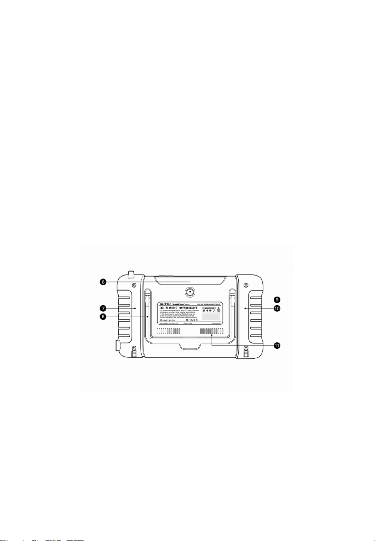
Figure 2-2 MaxiVideo MV500 -1 Display Tablet Back View
6. Collapsible Stand – extends from the back at 30/60/90 degree angles to
allow hands-free viewing of the display tablet.
7. Built-in Magnet (Left)
8. Rear Camera
9. Built-in Battery
4
Page 11

10. Built-in Magnet (Right)
11. Loudspeaker
Figure 2-3 MaxiVideo MV500-1 Display Tablet Top View
12. DC Power Supply Input Port – connects the 5 volt power adapter to
charge.
13. HDMI Port
14. Mini USB Port
15. SD Card Slot
16. Lock/Power Button – turns the device on & off with long press (Power off,
Reboot, Airplane mode, Silent mode), or locks the screen with short
press.
Power Sources
The display tablet can receive power from any of the following sources:
Internal Battery Pack
DC Power Supply
Internal Battery Pack
The display tablet can be powered with the internal rechargeable battery,
which if fully charged can provide sufficient power for about 3.5 hours of
continuous operation.
DC Power Supply
The display tablet can be powered from a wall socket using the DC power
adapter. The DC power supply also charges the internal battery pack.
5
Page 12

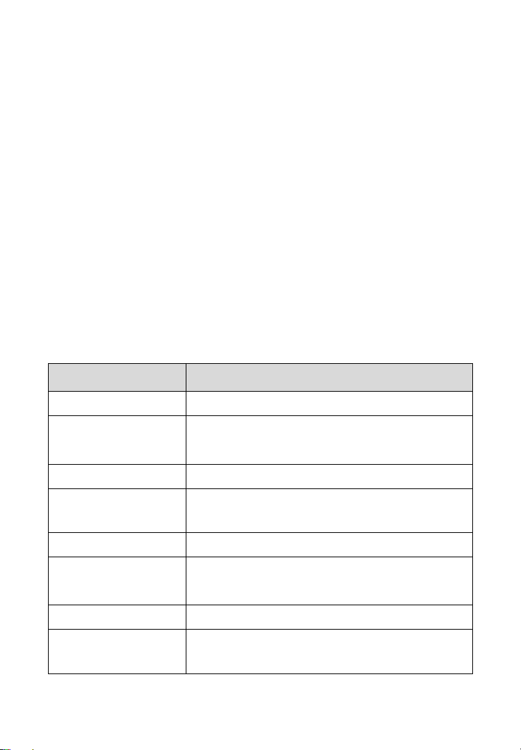
Technical Specifications
Table 2-1 Display Tablet Specifications
Item Description
Recommended Use
Operating System
Processor
Memory
Display
Dimensions
Connectivity
Wi-Fi
Camera
Sensor
Audio Input/Output
Power and Battery
Indoor
AndroidTM 4.4.2, KitKat
RockChip RK3188 Cortex-A9 quad-core processor
(1.6 GHz)
1G RAM DDR3 & 16GB ROM
5.0 inch LCD capacitive touchscreen with
1280x720 resolution
195.2 x 115.6 x 32.4 mm (7.7" x 4.6" x 1.3")
Mini USB 2.0
HDMI Type A
SD Card (Supports up to 32GB)
802.11 b/g/n
Rear-facing, 5.0 Megapixel
Gravity Accelerometer
Microphone
Single Speaker
3.7 V/3200 mAh lithium-polymer battery
Charges via 5 VDC power supply
Tested Battery Life
Battery Charging
Input
Power Consumption
Operating Temp.
Around 3.5 hours of continuous use
5 V/3 A
3 W
-10 to 60°C ( 14 to 140°F)
6
Page 13
Item Description
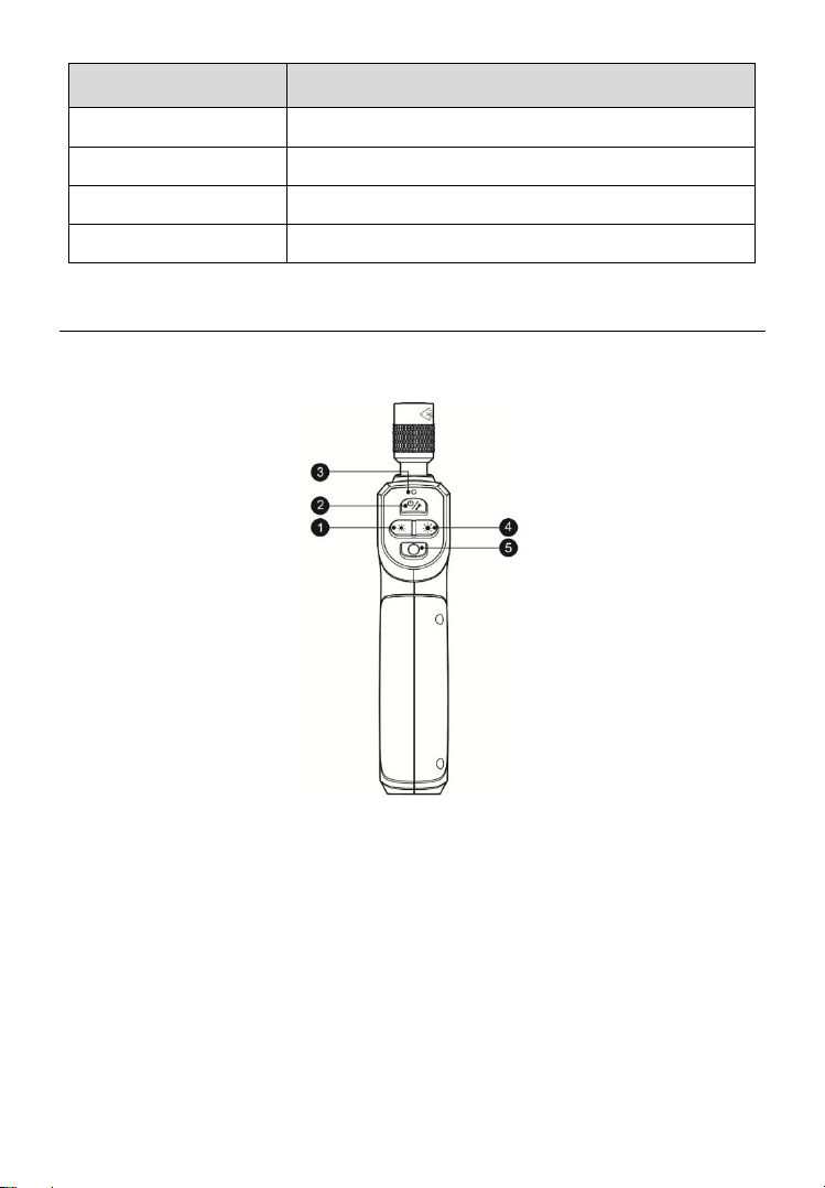
Figure 2-4 MaxiVideo MV500-2 Handle Front View
Storage Temp.
Operating Humidity
Housing
Net Weight
-20 to 70°C (-4 to 158°F)
5% - 95% non-condensing
Strong plastic housing with protective rubber boot
463 g (1.02 lb.)
MV500-2 Handle, Cable and Imager Heads
Functional Description
1. LED Light Dimmer Button –decreases LED light brightness.
2. Power Button – turns on/off the tool with long press, or turns on/off the
flashlight with short press.
3. Power LED Light – indicates battery level & charging status.
The power LED light displays different colors in response to the following
scenarios:
7
Page 14
A. Green:
Illuminates green when the MV500-2 handle is charging and the
battery level is above 90%.
Illuminates green when the MV500-2 handle is powered on and the
battery level is above 15%.
B. Red:
Illuminates red when the MV500-2 handle is powered on and the
battery level is below 15%.
C. Yellow:
Illuminates yellow when the MV500-2 handle is charging and the
battery level is below 90%.
4. LED Light Brighter Button –increases LED light brightness.
5. Shutter Button – starts capturing image or video.
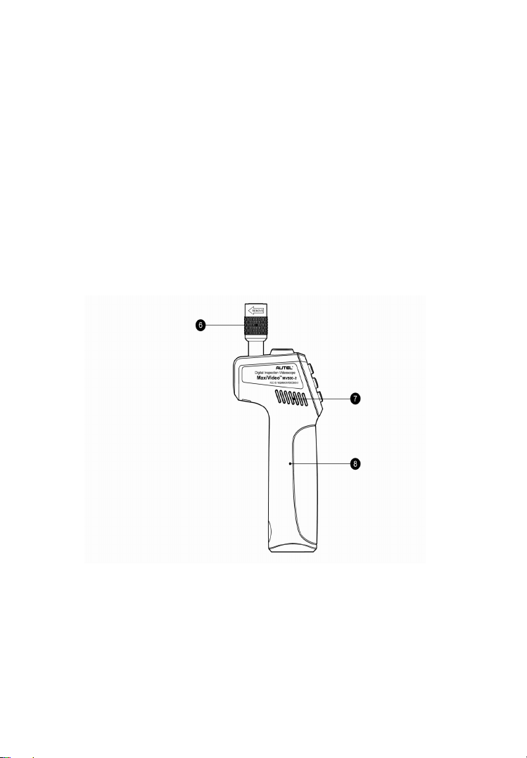
Figure 2-5 MaxiVideo MV500-2 Handle Left Side View
6. Knurled knob
7. Heat sink
8. Built-in Battery
8
Page 15
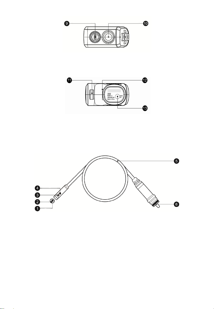
Figure 2-6 MaxiVideo MV 500-2 Handle Top View
9. USB Port
10. Flashlight
Figure 2-7 MaxiVideo MV500-2 Handle Bottom View
11. Rabbet
12. Round-shaped Rabbet
13. Power Supply Input Port – connects the 5 volt power adapter to charge.
Figure 2-8 MaxiVideo MV500-2 Cable and Imager Heads
1. Front Imager Head
2. Front LED Light
3. Side LED Light
4. Side Imager Head
5. Cable
6. USB Plug
9
Page 16
Power Sources
Item
Recommended Use
Indoor
Processor
Grain GM8287 processor (792 MHz ARM-based
32-bit RISC)
Memory
256MB RAM & 16MB ROM
Optimal Viewing
Distance
2.5 cm to 35.6 cm (1" to 14")
Dimensions
180.2 x 73.8 x 33.6 mm (7.1" x 2.9" x 1.3")
Power Supply
Built-in rechargeable lithium-ion battery pack (3.7
V/2600 mAh)
Tested Battery Life
Around 2.8 hours of continuous use
Battery Charging
Input
5 V/3 A
The handle can receive power from any of the following sources:
Internal Battery Pack
DC Power Supply
Internal Battery Pack
The handle can be powered with the internal rechargeable battery, which if
fully charged can provide sufficient power for about 2.8 hours of continuous
operation.
DC Power Supply
The handle can be powered from a wall socket using the DC power adapter.
The DC power supply also charges the internal battery pack.
Technical Specifications
Table 2-2 MV500-2 Handle Specifications
Description
10
Page 17

Item
Description
Net Weight
290 g (0.64 lb.)
Image Capture
JPG images (1280 x 720)
H.264 videos (1280 x 720)
Image Controls
Zoom, low light vision
Lighting
Fully adjustable LED light
40 Lm (flashlight)
Cable Reach
1 m (39.4")
Imager Heads
8.5 mm (0.33"), 1.0 Megapixel
Waterproof
1.6 m (63") (Imager heads and cable)
Additional Port
Mini USB – 10 Pin
Power Consumption
3 W
Operating Temp.
Handle & cable: 0°C to 65°C (32°F to 149°F)
Storage Temp.
Operating Humidity
Video Output
H.264
Wi-Fi
802.11 b/g/n
Handle & cable: -20°C to 70°C (-4°F to 158°F)
5% - 95% non-condensing
Accessories Included
1) User Manual
2) Imager Heads and Cable (8.5 mm)
3) Magnet and Hook
4) Charger
5) Mini USB Cable
6) HDMI Cable
7) Protective Carrying Case
11
Page 18

Installation and Connection
Figure 3-1
The Display Tablet and Handle Connection
To connect the display tablet and handle, insert the rubber protrusion on the
top right of the display tablet into the corresponding rabbet on the back of the
handle and the round-shaped magnet on the right bottom of the display tablet
into the corresponding round rabbet on the back of the handle (Fig 3-1).
Make sure they are properly aligned for firm connection.
The Imager Heads and Cable Installation
To use the tool, the imager heads and cable must be connected to the handle.
To connect the cable to the handle, make sure the key and slot (Fig 3-2) are
properly aligned. Once they are aligned, finger-tighten the knurled knob to
hold the connection firmly in place.
12
Page 19

Accessories Installation
Figure 3-3 Accessories
Figure 3-2
Figure 3-4
Figure 3-5
The two accessories include one magnet and one hook (Fig 3-3). Both are
attached to the imager head in the same manner. Hold the accessory and the
imager head as shown in Fig 3-4. Slip the end of the accessory over the
imager head and then fix the accessory as shown in Fig 3-5.
Micro SD Card Installation
To insert a Micro SD card into the Micro SD card slot, make sure the pins are
facing away from the screen. To remove the Micro SD card, gently push the
Micro SD card inward and then release to eject it from the card slot.
NOTE
Micro SD card slot provides for additional memory, but Micro SD card is
optional and not included. Different Micro SD cards can be used to insert into
the Micro SD card slot. The maximum 32GB of the Micro SD card can be
supported.
13
Page 20

Mini USB Cable Connection
Use the supplied mini USB cable to connect the tool to a PC to upload and
view captured photos and videos. When the display tablet is successfully
connected to the PC, a small window will pop up on the screen of the PC to
allow you to manage the photos and videos stored in the display tablet. You
would also find a file named as “MV500 PC’s Portable Devices or
Others section.
-2” in the
HDMI Cable Connection
Insert the HDMI cable into the HDMI port of the tool and the other end of the
cable into the HDMI port of a TV, the LCD screen will output a high quality
real-time image.
14
Page 21

Battery Charging Precautions
To reduce the risk of serious injury, read these precautions and the label on
charger’s surface carefully before using.
Battery Charging Safety
Do not probe charger with conductive objects.
Do not use charger if it has been dropped or damaged in any way.
Charge battery between 10°C (50° F ) and 45°C (113°F).
When in use, the charger shall be kept out of heat, high voltage and avoid
children’s touching.
Use the supplied charger. Do not charge the battery over 24 hours.
Do not cover the charger while in use.
Unplug the charger from outlet before attempting any maintenance or
cleaning.
Do not store charger in damp, wet or explosive environment.
Do not open charger housing. Have repairs performed only at authorized
locations.
Do not charge battery near fire or in the sunlight.
Proper care will prevent serious damage to the charger.
Battery and Charger Specifications
Table 4-1 Specifications
Item Description
Charger Input
Charger Output
100-240 VAC, 50/60 Hz
5 VDC
15
Page 22

Item Description
Battery Type
3.7 V lithium-ion
Battery Capacity
Charging Time
Cooling
3200 mAh (display tablet)
2600 mAh (handle)
3 hours (display tablet)
2.8 hours (handle)
Active fan cooling
Fan (1.8 CFM, 0.05 CMM)
Charger Inspection
Before using, inspect the charger and fix any problems. Set up charger
according to these procedures to reduce the risk of injury from electric shock,
fire and other causes and prevent tool damage.
1. Make sure charger is unplugged. Inspect the power cord and charger for
damage or broken, worn, missing, misaligned, binding parts. If any
problems are found, do not use the charger until the parts have been
repaired or replaced.
2. Clean any oil, grease or dirt from the tool especially on the buttons. This
helps to prevent the tool from slipping from your hands and allows proper
ventilation.
3. Inspect if the warning label on charger’s surface is intact and readable.
4. Select appropriate location for charger before using. Check work area
for:
The charger must be between 10°C (50° F ) and 45°C (113°F) for
charging. If the temperature of either is outside of this range at any
point during charging, the operation will be suspended until the
charger is brought back to the correct temperature range.
Inspect that the plug fits correctly into the desired outlet.
The charger needs a clearance of at least 10 cm (4") on all sides to
maintain a proper operating temperature.
16
Page 23

Battery Charging Procedures
The device
mAh lithium-ion battery for the display tablet and a 2600 mAh lithium-ion
battery for the handle. When the battery level is below 15% and the tool is
not charging, the corresponding Battery Capacity icon on the top of the
display tablet screen will be red until the tool shut down automatically.
For both of the batteries, they can only be charged by charger:
To charge by charger:
has two 3.7 V built-in lithium-ion rechargeable batteries, a 3200
Locate the DC power source port of the tool.
With dry hands, connect the tool to the outlet with charger to start
charging.
NOTE
New batteries reach full capacity after approximately 3 to 5 charging and
discharging cycles.
17
Page 24

Operation Instructions
Name
Icon
Description
Rear Camera
Tap this icon to display different camera modes
or choose rear camera mode.
Front Camera
Tap this icon for front camera mode.
Side Camera
Tap this icon for side camera mode.
Dual Camera
Tap this icon for dual camera mode.
Rotate (Main)
Tap this icon to rotate the main window by 90°
clockwise in dual camera mode.
Rotate (Small)
Tap this icon to rotate the secondary window by
90°clockwise in dual camera mode.
Rotate
Tap this icon to rotate the live image screen by
90 ° clockwise in rear camera mode, front
camera mode, and side camera mode.
Settings
Tap this icon to open the setting screen to set
Wi-Fi, Color Mode, Date & Time, etc.
Always wear safety eye protection to protect your eyes against dirt and other
objects. Follow operation instructions to reduce the risk of injury from electric
shock, entanglement and other causes.
Navigation
In the MV500-1 display tablet system, each screen contains a number of icons
that allow you to make desired selections and controls. The table below
provides a brief description of the operations of the icons in the system.
Table 5-1 Icons
18
Page 25

19
Name
Icon
Description
Shutter
Tap this icon to take photos.
Start
Tap this icon to begin video shooting.
Stop
Tap this icon to stop video shooting or message
recording.
Video/Camera
Tap this icon to switch between still image and
video mode.
Back
Tap this icon to return to the previous screen.
Dropdown
Tap this icon to show all the items in the list.
Collapse
Tap this icon to hide all the items in the list.
Handle Battery
Indicates the battery level of the handle.
Display Tablet
Battery
Indicates the battery level of the display tablet.
Edit
Tap this icon to edit the image.
Record
Tap this icon to record an audio message for
an image.
Play
Tap this icon to play the exiting audio message
of an image.
Delete
Tap this icon to delete the selected items.
Cancel
Tap this icon to exit without saving the made
marks.
Save
Tap this icon to exit and save all the made
marks.
Freestyle
Marks
Tap this icon to make freestyle marks on the
selected picture.
Arrow
Tap this icon to make arrows on the selected
picture.
Page 26

Name
Icon
Description
Circle
Tap this icon to circle desired areas on the
picture.
Square
Tap this icon to square desired areas on the
picture.
Color
Tap this icon to choose different colors for the
marks.
Undo
Tap this icon to undo the previous marks one
by one.
Restore
Tap this icon to restore the deleted marks one
by one.
Recording
Indicates the audio message is being recorded.
Splash Screen
Figure 5-1 Sample Splash Screen
When the tool is powered on, the first screen displayed is referred to as the
splash screen (Fig 5-1). This screen tells you the tool is booting up. Once the
tool is fully powered up, the screen will automatically switch to the live screen.
Live Screen
The live screen is where you can do most of your work. By default, a live
20
Page 27

image of what the rear camera sees is displayed on the screen. You can
Figure 5-2 Sample Live Screen
zoom, rotate images and videos, view and capture photos and videos from
this screen.
Basic Operation
NOTE
When in operation, the cable can be bent into a certain shape. This may help
you operate the cable into confined areas.
IMPORTANT
Keep the cable away from heat, oil, sharp edges and moving parts. Replace
damaged cables immediately.
Getting Started
1) To turn the tool on, hold the display tablet with LCD screen facing you.
Long press the Power button to turn it on. The power LED light will
illuminate green. Wait for two seconds, the first screen – a splash screen
will boot up and then a live screen with real-time image will appear for
you to do most of your work.
2) Long press the Power button of the handle to turn it on.
3) To connect the display tablet with the handle via Wi-Fi.
A. Tap the Settings icon on the right side of the LCD screen.
21
Page 28

B. Tap Wi-Fi and turn it on.
Playback
Rear Camera
C. Tap handle Wi-Fi in the list of Wi-Fi of the MV500-2 handle, then it
would automatically connect.
D. Tap Save on the top right of the screen to go back to the previous
screen.
Live Image Management
Shutter Rotate
Video/Camera Settings
Playback
This icon displays the most recent photo/video taken. You may tap it to view
photos and videos in Built-in Storage and External Storage, or edit and
delete your photos and videos one by one or in groups.
When viewing the pictures, you can edit, record audio message, zoom and
roll, below is the detailed instruction for each operation.
Picture Editing
Tap the Edit icon on the top right of the screen to go to editing interface which
allows you to make marks on the images captured.
22
Page 29

Freestyle Marks – tap the Freestyle Marks icon on the top and then
Figure 5-3 Sample Editing Screen
use your finger to make marks on the picture.
Arrow – tap the Arrow icon on the top and then use your finger to slide
on the screen to make arrows.
Circle –tap the Circle icon on the top and then use your finger to slide
on the screen to make different sizes of circles.
Square – tap the Square icon on the top and slide on the screen to
make different sizes of square or rectangle.
Color – tap the Color icon on the top to choose from the six colors (black,
white, blue, green, yellow, and red) for the marks. By default the tool
uses yellow.
Save – tap the green
Cancel – tap the red
Audio Message Recording
Tap the Record icon on the top right of the screen to record an audio
message for the picture and tap the Stop icon to end the recording.
For a picture with an audio message, tap the Play icon on the top right of the
screen to play the existing audio message. Tap the Delete icon on the top
right of the screen and choose Delete Recording to delete the recorded
audio message.
√ to save all made marks.
× to cancel all made marks.
23
Page 30

Zoom
Figure 5-4 Sample Audio Recording Screen
Double click the screen to zoom in or out the picture when viewing. Or twofinger press the screen to pinch open or pinch close for zooming in and
zooming out.
Roll
Finger slide left or right for picture viewing.
Shutter
Tap this button or press OK button on the handle to capture a photo in any
camera mode or begin capturing video in video mode. Simultaneously the
photo or video will be saved to built-in storage or external storage (if SD card
is available) depending on the storage setting.
NOTE
For dual camera mode, only live image/video on the main window can be
captured, but you can switch live images/videos of the two cameras then
capture the one you want.
Video/Camera
Tap this button to switch between still image and video modes.
Rear Camera
Tap this button to choose displayed camera modes. There are four modes.
24
Page 31

They are front camera, side camera, dual camera, rear camera from left to
right. For the dual camera mode, tap the secondary window on the right
bottom to switch live images of the two cameras on the main window for better
view.
Rotate
Tap this button to control the direction of the real-time image. The real-time
image will do
mode, there is a main Rotate icon for the main window and a small Rotate
icon for the secondary window so that you can choose to rotate the image
you want by tapping the corresponding Rotate icon.
a 90o clockwise rotation for each tap of the icon. In dual camera
Settings
Tap this button to entering the setting interface. See
chapter 6 for details.
Adjusting LED Light Brightness
To adjust the two LEDs’ light intensity on the cable, press the Dimmer button
or the Brighter button on the handle to decrease or increase the brightness.
This can also be achieved by tapping the middle of the LCD screen and
sliding the two LED Light icons on the two brightness indicator bars with the
left one for the front camera and the right for the side camera. The higher the
icon is, the brighter the LED will be.
Operation Precautions
Use the tool only as directed. Do not operate the tool unless the user
manual has been read thoroughly and proper training has been
completed.
The display unit is not waterproof. The imager heads and cable are
waterproof, but not acid-proof or fireproof. Avoid submersing the imager
heads and cable into corrosive, oily places and be sure to keep the
imager heads and cable away from high temperature objects.
Do not immerse the tool and display unit in water. Such measures
increase the risk of electric shock and damage.
25
Page 32

Do not use excessive force to insert or withdraw the imager heads and
cable. This may result in damage to the tool or inspection area.
Do not use the imager heads and cable to modify surroundings, clear
pathways or clogged areas.
Do not place the imager heads and cable into anything or anywhere that
may contain a live electric charge or moving parts, which increases the
risk of electric shock or entanglement injuries.
Do not use the tool for personal inspection or medical use in any way.
This is not a medical tool.
Do not eat or smoke while operating the tool. Use warm, soapy water to
wash hands and other body parts exposed to drain contents after using
the tool to inspect drains and other areas that may contain chemicals or
bacteria, which will help prevent contamination with toxic or infectious
material.
When the inspection is completed, carefully withdraw the imager heads
and cable from inspection area.
Store idle components out of the reach of children and other untrained
persons.
Maintain the tool with care. Properly maintained tools are less likely to
cause injury.
Do not drop the tool, if the tool is dropped accidently, check for the
breakage and any other conditions that may affect its operation.
Use only accessories that are recommended by the manufacturer for the
tool.
Dry your hands when operating the tool or charging the battery.
Always use appropriate personal protective equipment while handling
and using the tool. Appropriate personal protective equipment usually
includes safety glasses and gloves, and may include latex or rubber
gloves, face shields, goggles, protective clothing, respirators and steel
toed footwear.
Protect against excessive heat. The tool should be kept away from heat
sources such as radiators, stoves or others that produce heat. Do not
use the tool near moving machinery or areas where the temperature will
exceed 45°C (113°F).
26
Page 33

Store the tool, charger and all cables in a locked area out of the reach of
children and people unfamiliar with the tool.
Tool Inspection
Before using, inspect your tool and correct any problems to reduce the risk of
serious injury from electric shock and other causes and prevent tool damage.
Make sure the power is OFF.
Clean any oil, grease or dirt from the tool, especially on the buttons and
ports. This helps prevent the tool from slipping from your hands.
Inspect the imager head lens for condensation. To avoid damaging the
tool, do not use the tool if condensation forms inside the imager heads.
Let the water evaporate before using again.
Inspect the full length of the cable for cracks or damage. A damaged
cable could allow water to enter the tool and increase the risk of electric
shock.
Make sure the connections between the display unit and imager heads
and cable are tight. All connections must be properly assembled for the
cable to be waterproof.
Check if the warning label is present, firmly attached and readable. Do
not operate the tool without caution label.
If the tool does not work well after being turned on, please have the tool
checked by a qualified technician. Any tool that cannot be controlled with
the power button is dangerous and must be repaired.
NOTE
Please follow these tips to avoid injury.
FOR WALLS: For inspecting the inside of walls, be sure to shut off the
circuit breaker of the whole house before using the tool.
FOR PIPES: If you suspect a metal pipe could contain an electric charge,
have a qualified electrician check the pipe before using.
FOR AUTOMOBILES: Be sure the automobile is not running during
inspection. Metal and liquid under the hood may be hot. Don’t get oil or
gas on the imager heads.
27
Page 34

Tool and Work Area Set-up
Set up the tool and work area according to these procedures to reduce the
risk of injury from electric shock, entanglement, and other causes and prevent
tool damage.
1) Check work area for:
Sufficient lighting.
Do not work in area until flammable sources have been identified
and corrected. The tool is not explosion proof and can cause sparks.
Do not use the tool while standing in water.
2) Check the area and determine if MaxiVideoTM MV500-1 Digital Inspection
Videoscope is the correct tool for the job.
Check the access to the area.
Check if there is any electric power supplied to the area to be
inspected.
Check if any liquid would occur during the inspection. The Imager
heads and cable are waterproof to a depth of 1 m (39.4"), greater
depths may cause leakage into the imager heads and cable and
cause electric shock or damage the tool. The display unit is not
waterproof and should not be exposed to wet conditions.
Check if any chemicals are present, especially in the case of drains.
Chemicals may damage the tool.
Check the temperature of the area. The working temperature of the
tool is between 0°C (32°F) and 45°C (113°F).
Check if any moving parts are present in the area.
3) Make sure the tool has been properly inspected.
4) Install the correct accessories for use in the appropriate application.
IMPORTANT
Make sure the tool has been powered off before performing maintenance.
Tool maintenance must be performed only by qualified repair personnel.
Maintenance performed by unqualified repair personnel could cause
injury.
28
Page 35

When maintaining, use only identical replacement parts. Use of
unauthorized parts or failure to follow maintenance instructions may
create a risk of electric shock or injury.
Do not attempt to take any pieces of the tool apart unless directed by the
manual.
Follow instructions to change accessories.
Do not use acetone to clean the tool. Instead, use only alcohol to swab
the connections. Avoid rubbing too hard on the LCD screen. After using,
wipe the display unit clean gently with a dry cloth.
Upon the completion of any maintenance of the tool, ask qualified repair
personnel to perform safety checks to examine if the tool is in proper
operating condition.
Stop using the tool if it starts smoking or emitting noxious fumes.
Always handle the tool with care. It is not shock-resistant.
Do not disassemble the tool beyond what is shown in the manual, doing
so will void your warranty.
29
Page 36

Settings
Selecting Settings application opens a setup interface, on which you can
adjust default setting and view information about the MV500-1 videoscope tool.
There are thirteen options available for the MV500-1 system settings:
Wi-Fi
Color Mode
Date and Time
Screen Brightness
Sound
Language
Storage Location
Scheduled Power-Off
Serial Number
Format
Restore Factory Settings
Version
Upgrade
Wi-Fi
This option allows you to connect the display tablet with the handle or the
Internet.
To connect to the handle
1. Tap the Settings icon on the live image screen.
2. Tap the Wi-Fi option on the column.
3. Tap the On/Off icon to turn the Wi-Fi on.
4. Tap handle Wi-Fi in the list of Wi-Fi of the MV500-2 Handle to
30
Page 37

connect. The Wi-Fi name of the handle is on the right side label.
Figure 6-1 Sample Handle Wi-Fi Connection
Only one handle can be connected for use at one time.
5. Tap Save on the top right corner or the Back arrow on the top left
corner to confirm and return to the Settings menu.
IMPORTANT
Each Autel MV500-2 handle communicates with one MV500-1 display tablet at
one time. Once connected for the first time, they will automatically connect
next time in use.
To connect to the Internet
1. Follow the 1-3 steps in To connect to the handle.
2. Tap Other Available Networks to select the Wi-Fi and input the
password in the Password blank when required. A typing screen
will show after a tap at the blank. You can choose to show password
by tapping the square box in front of Show password.
3. Tap Connect to confirm or Cancel.
4. Tap Save on the top right corner or the Back arrow on the top left
corner to confirm and return to the Settings menu.
31
Page 38

Color Mode
Figure 6-3 Sample Color Mode Setting
Figure 6-2 Sample Internet Connection
This option allows you to choose between Color mode and Gray mode for the
two cameras on the cable.
To choose the color mode
1. Tap the Settings icon on the live image screen.
2. Tap the Color/Gray icon to choose the mode you want. The pane of
the selected mode will be colored blue with the word in white.
3. Tap Save on the top right corner or the Back arrow on the top left
corner to confirm and return to the live image screen.
32
Page 39

NOTE
Figure 6-4 Sample Date and Time Setting
The Color/Gray mode only applies for the two cameras on the cable, not for
the rear camera on the display tablet. It would not work in rear camera mode.
Color is the default mode.
Date and Time
This option allows you to adjust the date and time for the MV500-1 system.
To adjust the Date and Time setting
1. Tap the Settings icon on the live image screen.
2. Tap the Date and Time option on the column.
3. To set date and time automatically, tap the box on the right of Set
Automatically, a tick will show afterwards. Please be noted that
connection to the Internet is necessary for this option, otherwise a
message “Please connect to the Internet to set date and time
automatically” will pop up, tap OK to go to Wi-Fi setting or tap
Cancel to quit this option.
4. To set date and time manually, roll up and down the digital bars for
date and time. Please be noted that this option is only available
when Set Automatically is not chosen, otherwise the digital bars
would be locked and unable to be rolled.
5. Tap Save to confirm and return to Settings menu.
33
Page 40

Screen Brightness
Figure 6-5 Sample Screen Brightness Setting
This option allows you to adjust brightness of the display screen.
To adjust screen brightness
1. Tap the Settings icon on the live image screen.
2. Tap the Screen Brightness option on the column.
3. Slide the Brightness icon left or right on the brightness indicator bar
for different level of screen brightness. The righter the icon is, the
brighter the screen would be.
4. Tap Save on the top right corner to confirm and return to Settings
menu.
Sound
This option allows you to adjust the sound of the microphone.
To adjust the sound
1. Tap the Settings icon on the live image screen.
2. Tap the Sound option on the column.
3. Slide the Sound icon left or right on the sound indicator bar for
different volume. The righter the icon is, the louder the sound would
be.
34
Page 41

4. Tap Save on the top right corner to confirm and return to Settings
Figure 6-6 Sample Sound Setting
Figure 6-7 Sample Language Setting
menu.
Language
This option allows you to select the display language for the MV500-1 system.
To select the language setting
1. Tap the Settings icon on the live image screen.
2. Tap the Language option on the column.
3. Select the desired language and a tick icon will appear on the right
of the selected language. English is the default language.
35
Page 42

NOTE
Figure 6-8 Sample Storage Location Setting
The screen will automatically return to the Primary Settings menu and display
in the selected language after the selection.
Storage Location
This option allows you to choose the storage location of captured pictures
and videos beforehand for the MV500-1 system.
To adjust the storage location setting
1. Tap the Settings icon on the live image screen.
2. Tap the Storage Location option on the column.
3. Select the desired location. A tick will display to the right of the
selected location.
4. Tap Save on the top right corner to confirm and return to Settings
menu.
NOTE
External Storage is only available when a SD card is inserted into the SD card
slot beforehand. And after the selection, captured pictures and videos will be
automatically stored in the selected location all the time unless you change
the location again.
36
Page 43

Scheduled Power-off
This option allows you to schedule an automatic power-off in a certain time
for the display tablet.
To adjust the scheduled power-off setting
1. Tap the Settings icon on the live image screen.
2. Tap the Scheduled Power-off option on the column.
Figure 6-9 Sample Scheduled Power-off Setting
3. Select one of the 7 choices: Disable, In 10 minutes, In 20 minutes,
In 30 minutes, In 40 minutes, In 50 minutes, In 60 minutes. A tick will
display to the right of the selected time. Manual time setting is also
available. You can tap Set Time and roll up and down in the setting
screen then tap OK to confirm (Fig 6-10).
4. Tap Save on the top right corner to confirm and return to Settings
menu.
37
Page 44

Serial Number
Figure 6-11 Sample Serial Number Screen
Figure 6-10 Sample Set Time Screen
This option shows the serial number of the MV500-1 display tablet.
Format
This option allows you to format SD card.
To adjust the format setting
1. Tap the Settings icon on the live image screen.
2. Tap the Format option on the column.
38
Page 45

3. Tap OK in the confirm screen to start formatting, or tap Cancel to
Figure 6-12 Sample Format SD Card Setting
quit formatting. When formatting is finished, it will take you back to
the primary settings screen. Please be noted that SD card content
cannot be restored after formatting.
NOTE
Before performing the formatting, make sure you have viewed the files in the
SD card thoroughly.
Restore Factory Settings
This option allows you to reset all the settings.
To adjust the restore factory settings
1. Tap the Settings icon on the live image screen.
2. Tap the Restore Factory Settings option on the column and a
confirm screen will show.
3. Tap OK in the confirm screen, or Cancel. And the display tablet will
reboot automatically after the restoration.
39
Page 46

NOTE
Figure 6-14 Sample Version Screen
Figure 6-13 Sample Restore Factory Settings
Selecting Restore Factory Settings will erase all user-added content and
reset all settings. This action is irreversible. Please back-up your data if
needed.
Version
This option shows you the information of the MV500-1 system. There are three
items: Management Program Version, Handle System Version, and Display
Tablet System Version.
40
Page 47

NOTE
Figure 6-15 Sample Upgrade Screen 1
Handle System Version shows the system version information of the last
handle that has connected to the display tablet or the handle that is
connecting with the display tablet. If no handle had connected to the display
tablet, “Connect to the Handle” will be displayed instead of the version
information.
Update
Autel frequently releases software updates that you can download. This
Update option allows you to check for the latest version of management
program, handle system, display tablet system and update them. Connection
to the Internet is necessary for this option.
IMPORTANT
Please make sure the management program, handle system and display
tablet system are updated to the latest version. Incompatible versions may
result in malfunctioning of the tool.
If the display tablet is connected to the Internet, a window with management
program, handle system and display tablet system version will pop up for you
to update.
41
Page 48

NOTE
Figure 6-16 Sample Upgrade Screen 2
Handle System Version shows the system version information of the last
handle that has connected to the display tablet or the handle that is
connecting with the display tablet. If no handle had connected to the display
tablet, Handle System Version would not be displayed. To update the handle
system, please make sure the handle is connected with the display tablet.
If the display tablet is not connected to the Internet, a screen will direct you
to network settings (Fig 6-16).
Tap Head to network settings and connect to the Internet. See To connect
to the Internet in Wi-Fi on
Page 32 for details.
Management Program
1. Tap the New version available on the right side of Management
Program Version. Current version is the latest means the version in
use for management program is the latest, there is no need to update.
2. Tap Download in the download screen.
3. Tap Install after downloading to finish the installation. Then the tablet
would automatically turn to live screen afterwards.
42
Page 49

Handle System
Figure 6-17 Sample Management Program Update
Figure 6-18 Sample Handle System Update Screen 1
1. Tap the New version available on the right side of Handle System
Version. Current version is the latest means the version in use for the
handle system is the latest, there is no need to update.
2. Tap Download in the download screen.
3. Tap Install after downloading. There would be a screen direct you to
connect the display tablet with the handle Wi-Fi. Follow the on-screen
navigation to connect. The display tablet will send the downloaded data
to the MV500-2 handle for update, and the handle will automatically power
off after the installation is finished.
43
Page 50

Display Tablet System
Figure 6-19 Sample Handle System Update Screen 2
Figure 6-20 Sample Display Tablet System Update
1. Tap the New version available on the right side of Display Tablet
System Version. Current version is the latest means the version in
use for display tablet system is the latest, there is no need to update.
2. Tap Download in the download screen.
3. Tap Install after downloading to finish the installation. The display tablet
will automatically reboot during installation.
44
Page 51

Troubleshooting
Symptoms
Possible
Reason
Solutions
Display is on, but does not show
image.
Cable
connection is
loose.
Check and
reattach.
Check if it is
covered by debris
and remove it.
LED on imager heads are dim at
max brightness, display tablet
changes between monochrome
and color mode, and then turns
itself OFF after a short period.
Low battery.
Charge battery.
The tool cannot turn on.
Dead battery.
Replace battery.
Table 7-1 Troubleshooting
Imager heads
are covered by
debris.
45
Page 52

Compliance Information
FCC COMPLIANCE Display Tablet FCC ID: WQ8MAXIVIDEO500-1
Handle FCC ID: WQ8MAXIVIDEO500-2
Both devices comply with Part 15 of the FCC Rules and with RSS of Industry
Canada. Operation is subject to the following two conditions:
1. This device may not cause harmful interference.
2. This device must accept any interference received, including
interference that may cause undesired operation.
Cet appareil est conforme aux CNR exempts de licence d'Industrie Canada.
Son fonctionnement est soumis aux deux conditions suivantes:
1. Ce dispositif ne peut causer des interferences; et
2. Ce dispositif doit accepter toute interférence, y compris les interférences
qui peuvent causer un mauvais fonctionnement de l'appareil.
WARNING
Changes or modifications not expressly approved by the party responsible
for compliance could void the user's authority to operate the equipment.
NOTE
This equipment has been tested and found to comply with the limits for a
Class B digital device, pursuant to Part 15 of the FCC Rules. These limits are
designed to provide reasonable protection against harmful interference in a
residential installation.
This equipment generate uses and can radiate radio frequency energy and,
if not installed and used in accordance with the instructions, may cause
harmful interference to radio communications. However, there is no
guarantee that interference will not occur in a particular installation. If the
equipment does cause harmful interference to radio or television reception,
which can be determined by turning the equipment off and on, the user is
46
Page 53

encouraged to try to correct the interference by one or more of the following
measures:
1. Reorient or relocate the receiving antenna.
2. Increase the separation between the equipment and receiver.
3. Connect the equipment into an outlet on a circuit different from that to
which the receiver is connected.
4. Consult the dealer or an experienced radio/TV technician for help.
Changes or modifications not expressly approved by the party responsible
for compliance could void the user's authority to operate the equipment.
RF WARNING STATEMENT
The device has been evaluated to meet general RF exposure requirement.
The device can be used in portable exposure condition without restriction.
The term “IC” before the radio certification number only signifies that IC
technical specifications were met.
RoHS COMPLIANCE
Both devices are declared to be in compliance with the European RoHS
Directive 2011/65/EU.
CE COMPLIANCE
This product is declared to conform to the essential requirements of the
following Directives and carries the CE mark accordingly:
EMC Directive 2014/30/EU
R&TTE Directive 1999/5/EC
Low Voltage Directive 2014/35/EU
47
Page 54

Warranty and Service
Limited One Year Warranty
Autel Intelligent Technology Corp., Ltd. (the Company) warrants to the
original retail purchaser of this MaxiVideo MV500-1,that should this product or
any part thereof during normal consumer usage and conditions, be proven
defective in material or workmanship that results in product failure within 1
year period from the date of delivery, such defect(s) will be repaired, or
replaced (with new or rebuilt parts) with Proof of Purchase, at the Company’s
option, without charge for parts or labor directly related to the defect(s).
The Company shall not be liable for any incidental or consequential damages
arising from the use, misuse, or mounting of the device. Some states do not
allow limitation on how long an implied warranty lasts, so the above limitations
may not apply to you.
This warranty does not apply to:
1) Products subjected to abnormal use or conditions, accident, mishandling,
neglect, unauthorized alteration, misuse, improper installation or repair
or improper storage;
2) Products whose mechanical serial number or electronic serial number
has been removed, altered or defaced;
3) Damage from exposure to excessive temperatures or extreme
environmental conditions;
4) Damage resulting from connection to, or use of any accessory or other
product not approved or authorized by the Company;
5) Defects in appearance, cosmetic, decorative or structural items such as
framing and non-operative parts.
6) Products damaged from external causes such as fire, dirt, sand, battery
leakage, blown fuse, theft or improper usage of any electrical source.
48
Page 55

Service Information
If you have any questions, please contact your local store, distributor or visit
our website
If it becomes necessary to return the tool for repair, please download and fill
the Technical Support Form from www.auteltech.com, contact your local
distributor for more information.
Other Services
Accessories can be purchased from Autel authorized suppliers and your local
distributors.
www.autel.com.
49
Page 56

FCC WARNING:
Any Changes or modifications not expressly approved by the party responsible for compliance could void
the user's authority to operate the equipment.
This device complies with part 15 of the FCC Rules. Operation is subject to the following two conditions:
(1) This device may not cause harmful interference, and (2) this device must accept any interference
received, including interference that may cause undesired operation.
(b) For a Class B digital device or peripheral, the instructions furnished the user shall include the
following or similar statement, placed in a prominent location in the text of the manual:
Note: This equipment has been tested and found to comply with the limits for a Class B digital device,
pursuant to part 15 of the FCC Rules. These limits are designed to provide reasonable protection against
harmful interference in a residential installation. This equipment generates, uses and can radiate radio
frequency energy and, if not installed and used in accordance with the instructions, may cause harmful
interference to radio communications. However, there is no guarantee that interference will not occur in a
particular installation. If this equipment does cause harmful interference to radio or television reception,
which can be determined by turning the equipment off and on, the user is encouraged to try to correct the
interference by one or more of the following measures:
—Reorient or relocate the receiving antenna.
—Increase the separation between the equipment and receiver.
—Connect the equipment into an outlet on a circuit different from that to which the receiver is connected.
—Consult the dealer or an experienced radio/TV technician for help.
SAR tests are conducted using standard operating positions accepted by the FCC with the
device transmitting at its highest certified power level in all tested frequency bands, although
the SAR is determined at the highest certified power level, the actual SAR level of the device
while operating can be well below the maximum value.
Before a new device is a available for sale to the public, it must be tested and certified to
the FCC that it does not exceed the exposure limit established by the FCC, Tests for each
device are performed in positions and locations (e.g. at the ear and worn on the body) as
required by the FCC.
For body worn operation, this model device has been tested and
guidelines when used with an accessory designated for this product or when used with an accessory that
contains no metal in assembly. Non-compliance with the above restrictions may result in violation of RF
exposure guidelines.
meets the FCC RF exposure
 Loading...