

Page 1

Trademarks
Autel, MaxiSys, MaxiCheck, MaxiDAS, MaxiDiag, MaxiRecorder,
MaxiScan, and MaxiTPMS are trademarks of Autel Intelligent
Technology Corp., Ltd., registered in China, the United States and other
countries. All other marks are trademarks or registered trademarks of
their respective holders.
Copyright Information
No part of this manual may be reproduced, stored in a retrieval system
or transmitted, in any form or by any means, electronic, mechanical,
photocopying, recording, or otherwise, without the prior written
permission of Autel.
Disclaimer of Warranties and Limitation of Liabilities
All information, specifications and illustrations in this manual are based
on the latest information available at the time of printing.
Autel reserves the right to make changes at any time without notice.
While information of this manual has been carefully checked for
accuracy, no guarantee is given for the completeness and correctness of
the contents, including but not limited to the product specifications,
functions, and illustrations.
Autel will not be liable for any direct damages or for any special,
incidental, or indirect damages or for any consequential economic
damages.
IMPORTANT
Before operating or maintaining this unit, please read this manual
carefully, paying extra attention to the safety warnings and precautions.
For Services and Support
http://pro.autel.com
www.autel.com
1-855-288-3587/1-855-AUTEL US (North America)
086-755-86147779 (Chin
0
Support@aute
l.com
a)
For technical assistance in all other markets, please contact your local
selling agent.
i
Page 2

Safety Instructions
To prevent personal injury or damage to vehicles and/or the inspection
tool, read this instruction manual first and observe the following safety
precautions at a minimum whenever working on a vehicle.
Work Area Safety
Always perform automotive testing in a safe environment.
Keep clothing, hair, hands, tools, test equipment, etc. away from
all moving or hot engine parts. The cable shall be operated under
60 °C (140 °F).
Operate the tool in a well-ventilated work area.
Do not operate the tool in a potentially combustive atmosphere,
such as in the presence of flammable liquids, gases, or heavy dust.
Keep a fire extinguisher for use on gasoline/chemical/electrical
fires nearby.
Do not use the tool around corrosive chemicals.
Keep bystanders, children and visitors away vehicle testing area.
Keep the tool dry, clean, free from oil, water and grease. Use a
mild detergent on a clean, damp cloth to clean the outside of the
tool when necessary.
Electrical Safety
Keep the tool away from grounded surfaces such as pipes,
radiators, ranges and refrigerators.
Do not expose the tool to rain or wet conditions. Water entering
the tool will increase the risk of electric risk.
ii
Page 3

Do not unplug the tool from the electrical outlet by pulling on
electrical cord. Never carry tool by cord. Keep cord away from
heat, oil, sharp edges or moving parts.
If operating the tool in a damp location is unavoidable, use a
ground fault circuit interrupter (GFCI) to protect the tool from
damage and the operator from injury.
Personal Safety
Do not use the tool while tired or under the influence of drugs,
alcohol, or medications. A moment of distraction can result in
serious personal injury.
Do not over-reach. Keep proper footing and balance at all times.
Proper footing and balance enable better control of the tool in
unexpected situations.
Always wear safety eye protection that meets ANSI standards.
Do not wear loose clothing or jewelry. Keep your hair, clothing,
and gloves away from moving parts.
Do not place the tool on any unstable cart or surface. The tool may
fall causing serious injury to a person or serious damage to the tool
itself.
Do not have liquids near the tool. Liquid increases the risk of
electric shock and damage to the tool.
Do not use the tool for personal or medical use.
The product is not shock-resistant. Handle it with care and be
careful not to drop it.
iii
Page 4

Contents
1. USING THE MANUAL ......................................................................................... 1
CONVENTIONS ......................................................................................................... 1
2. GENERAL INTRODUCTION ............................................................................. 3
2.1 DESCRIPTION ..................................................................................................... 3
2.2 SPECIFICATIONS ................................................................................................. 3
2.3 ACCESSORIES INCLUDED ................................................................................... 4
2.4 TOOL COMPONENTS AND PORTS ....................................................................... 5
2.5 BUTTONS AND CONTROLS .................................................................................. 8
3. INSTALLATION AND CONNECTION ........................................................... 10
3.1 THE IMAGER HEAD AND CABLE INSTALLATION .............................................. 10
3.2 ACCESSORIES INSTALLATION .......................................................................... 10
3.3 MINI USB CABLE CONNECTION ...................................................................... 11
4. BATTERY CHARGING PRECAUTIONS........................................................ 12
4.1 BATTERY CHARGING SAFETY .......................................................................... 12
4.2 BATTERY AND CHARGER SPECIFICATIONS ...................................................... 12
4.3 CHARGER INSPECTION ..................................................................................... 13
4.4 BATTERY CHARGING PROCEDURES ................................................................ 13
5 OPERATION INSTRUCTIONS ......................................................................... 15
5.1 OPERATION PRECAUTIONS .............................................................................. 15
iv
Page 5

APP INSTALLATION AND START ....................................................................... 16
5.2
5.3 ON-SCREEN NAVIGATION ................................................................................ 17
5.4 SETTINGS ........................................................................................................ 21
6 FIRMWARE UPGRADE .................................................................................... 26
7 TROUBLESHOOTING ....................................................................................... 28
8 COMPLIANCE INFORMATION ...................................................................... 29
9 WARRANTY INFORMATION ......................................................................... 30
9.1 LIMITED ONE YEAR WARRANTY ..................................................................... 30
9.2 SERVICE PROCEDURE ...................................................................................... 30
v
Page 6

1. Using the Manual
This manual contains device usage instructions.
Some illustrations shown in this manual may depict tool models and/or
optional equipment that are not included on or with your system. Contact
your sales representative for availability of tool options or accessories
not included.
Conventions
The following conventions are used.
Bold Text
Bold text is used to highlight selectable items such as buttons and menu
options.
Example:
Press the Power button.
Notes and Important Messages
Notes
A NOTE provides helpful information such as additional explanations,
tips, and comments.
Example:
NOTE
New batteries reach full capacity after approximately 3 to 5 charging and
discharging cycles.
Important
IMPORTANT indicates a situation which, if not avoided, may result in
damage to the test equipment or vehicle.
Example:
1
Page 7

IMPORTANT
Keep the cable away from heat, oil, sharp edges and moving parts.
Replace damaged cable immediately.
Hyperlinks
Hyperlinks or links that take you to other related articles, procedures, and
illustrations are available in electronic documents. Blue italic text
indicates a selectable hyperlink.
Illustrations
Illustrations used in this manual are samples, the actual testing screen
may vary for each vehicle being tested. Observe the menu titles and onscreen instructions to make correct option selection.
2
Page 8

2. General Introduction
2.1 Description
This premier Autel MaxiVideo MV160 is the next generation of digital
videoscope designed for smartphones. It features a two-megapixel
high-resolution camera and a standard 8.5mm camera probe, which
makes it easy to inspect difficult-to-reach areas with its semi-rigid
flexible cable and 10-level adjustable LED light. MV160 works
perfectly with both Android and iOS smartphones. With the Autel
MaxiVideo app, you can connect the videoscope to your smartphone
via Wi-Fi and edit photos, videos, and voice recordings directly on your
phone, and share with your customers and colleagues. The
multipurpose videoscope is an economical solution to inspect
machinery, facilities, and infrastructure in the safest and most cost-
effective manner possible.
This manual describes the construction and operation of the device and
how it works to examine difficult-to-reach areas.
2.2 Specifications
Recommended use
Optimal viewing
Distance
Image capture
Power supply
Indoor
0.79" to 2" (2 cm to 5 cm)
JPG images (1920 x 1080 pixels)
MP4 videos (1920 x 1080 pixels)
Built-in rechargeable lithium-ion battery
pack (3.7V/2600mAh)
3
Page 9

Tested battery life
Dimensions
Weight
Recording medium
Image controls
Lighting
Cable reach
Imager head
Waterproof
Additional ports
Approximately 4 hours of continuous use
237 x 63 x 123mm (9.33" x 2.48" x 4.84")
0.309 kg (0.68lbs)
Android & iOS smartphone
Zoom, low light vision
Fully adjustable LED; Flashlight
1m (39.4")
8.5mm (0.33"), 2 megapixel (1920 x 1080
pixels)
To a depth of 1m (39.4") (Imager heads
and cable only)
Mini USB
Main unit: 14°F to 122°F (-10°C to
Operating temp.
50°C);
Cable: 14°F to 140°F (-10°C to 60°C)
Storage temp.
Operating humidity
-4°F to 158°F (-20°C to 70°C)
5% - 95% non-condensing
2.3 Accessories Included
1) Imager Head and Cable (8.5mm)
2) Magnet, Hook, Mirror
3) Charger
4) Mini USB Cable
5) User Manual
4
Page 10
2.4 Tool Components and Ports
The MaxiVideo MV160 comes with the following items:
NOTE
Because of continuing improvements and modifications, actual product
may differ slightly from photo.
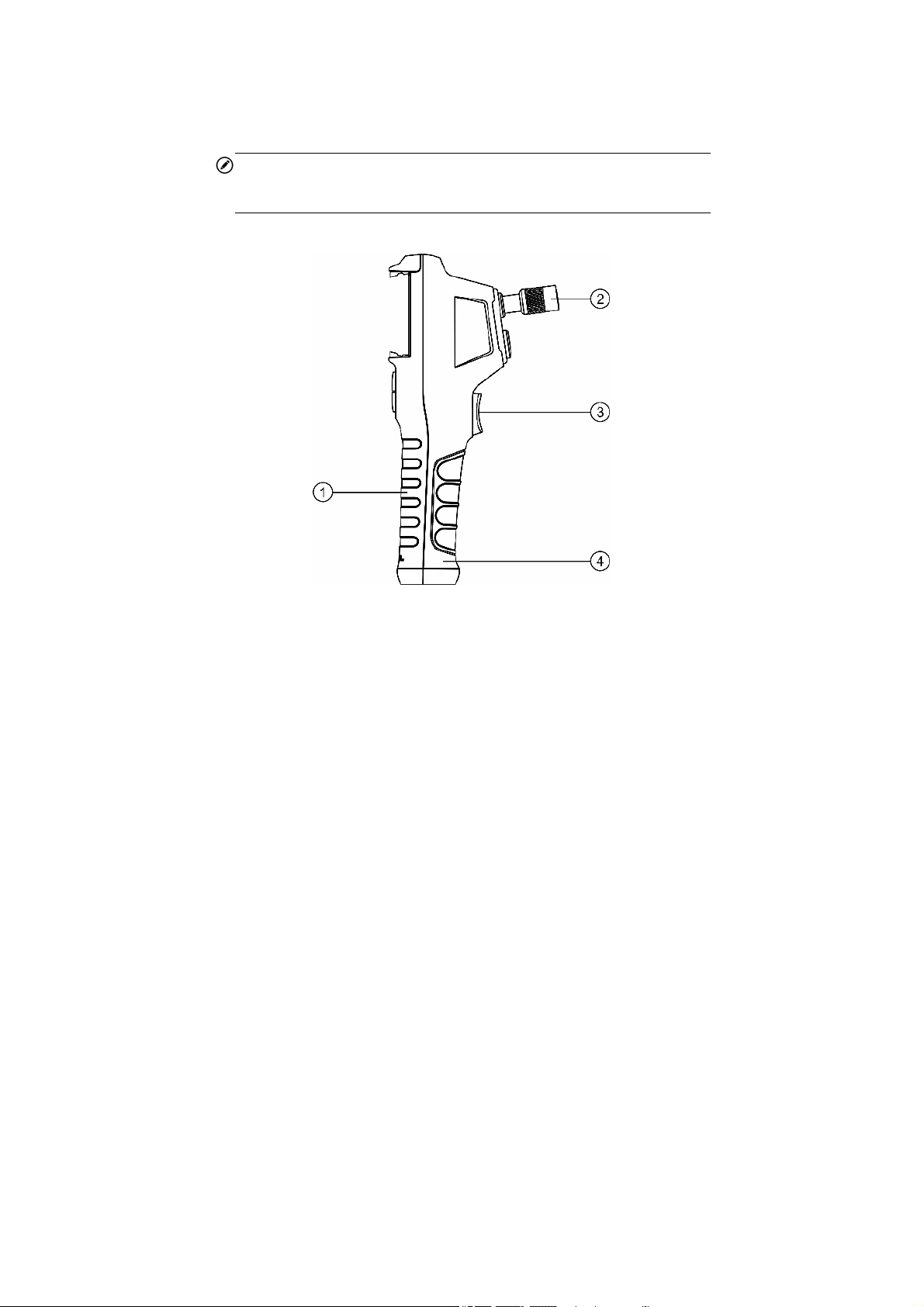
Figure 2-1 MaxiVideo MV160 Right Side View
1. Handheld Unit – Ergonomic tool with comfortable pistol grip design.
2. Knurled knob – Fastens the handheld unit with the imager head cable.
3. Shoot Button – Takes photos, starts and stops video recording.
4. Battery Compartment Cap – Covers the battery in the handle.
5
Page 11

Figure 2-2 MaxiVideo MV160 Back Side View
1. USB Port – Connects the handheld unit to the imager head and cable.
2. Flashlight – Illuminates low light environment.
Figure 2-3 MaxiVideo MV160 Top View
6
Page 12

1. Mini USB/Power Source Port – Connects the tool to a computer
with the supplied Mini USB cable for battery charging or firmware
updating. Connects the tool with the supplied Mini USB cable and
charger to power on the tool or to charge battery.
Figure 2-4 MaxiVideo MV160 Cable and Imager Head
1. Imager Head
2. LED Light
3. Cable
4. Alignment Key
Figure 2-5 MaxiVideo MV160 Accessories
7
Page 13

1. Accessory Magnet – Attaches to tool to pick up small metal objects
such as screws.
2. Accessory Hook – Attaches to tool to pick up wires or rings in pipes
or confined areas.
3. Accessory Mirror – Attaches to tool to inspect corners and
unreachable areas.
2.5 Buttons and Controls
e 2-6 MaxiVideo MV160 Buttons and Controls
Figur
A. Smartphone Mount – Clamps your smartphone.
B. Power LED – Lights yellow when charging, lights green when
powering on or charging is complete, and lights red when the battery
falls below 20 percent.
C. Power Button – Powers tool on and off. Press to switch between
8
Page 14

camera and video mode when a dual imager head cable is connected
(dual imager head cable is compatible but not included).
D. Flashlight Button – Turns flashlight on and off.
E. LED Brighter Button – Increases imager head LED brightness.
F. LED Dimmer Button – Decreases imager head LED brightness.
9
Page 15

3. Installation and Connection
3.1 The Imager Head and Cable Installation
To use the tool, the imager head and cable must be connected to the
handheld unit. To connect the cable to the handheld unit, align the key
on the probe connector with slot on the coupling (Figure 3-1). Push the
two ends together and, finger-tighten the collar to hold the connection
firmly in place.
Figure 3-1 Connect Imager with Cable
3.2 Accessories Installation
Three accessories are included: a magnet, a hook, and a mirror (Figure
2-4). All are attached to the imager head in the same manner. Detach the
cap from the imager head as shown in Figure 3-2 and Figure 3-3. Slip the
end of the accessory over the imager head and then secure the accessory
as shown in Figure 3-4 and Figure 3-5.
10
Page 16

Figure 3-2 Figure 3-3
Figure 3-4 Figure 3-5
3.3 Mini USB Cable Connection
Use the supplied Mini USB cable to connect the tool to a PC for
charging or firmware updating. For firmware updating, please refer to
6.2.
11
Page 17

4. Battery Charging Precautions
IMPORTANT
To reduce the risk of serious injury, read these precautions and
specification label on charger carefully before using.
4.1 Battery Charging Safety
Do not probe charger with conductive objects.
Do not use charger if it has been damaged.
Charge battery in temperatures above 41°F (5°C) and below 113°F
(45°C).
Keep charger out of the reach of children.
Use only the charger supplied.
Do not charge the battery for more than 24 hours.
Do not cover the charger while in use.
Do not clean charger while it is plugged into electrical outlet.
Do not store charger in damp, wet area or with corrosive liquids.
Do not open charger housing. Do not attempt to repair.
Do not charge battery near fire or in the sunlight or in direct heat.
Proper care will prevent serious damage to the charger.
4.2 Battery and Charger Specifications
Input
Battery Type
Battery Capacity
USB-5V
3.7V lithium-ion
2600mAh
12
Page 18

Input Current
Charging Time
1A Max(USB)
3-4 hours
4.3 Charger Inspection
IMPORTANT
Before using, inspect the charger for any damage. Set up charger
according to these procedures to reduce the risk of injury to persons and
tool. Inspect the charger for damage or modifications including broken,
worn, missing, misaligned or binding parts. Do not use charger if
damaged. The warning label on charger’s surface is intact and readable.
The tool should only be charged in an appropriate workspace,
with a temperature of between 41°F (5°C) and 113°F (45°C). If
the temperature is out of this range at any point during charging,
the operation will be suspended.
The charger should plug correctly into the desired electrical
outlet.
The charger should have a clearance of at least 4" (10 cm) on all
sides so as not to overheat.
4.4 Battery Charging Procedures
The tool has a 3.7V built-in rechargeable lithium-ion battery. If the
battery level is too low to continue operating, the tool will
automatically shut off.
There are two battery charging methods:
1) To charge battery by charger and Mini USB cable: Plug the
supplied Mini USB cable into the tool and into the charger hub and
plug the charger into the electrical outlet.
13
Page 19

2) To charge battery by computer: Plug the supplied Mini USB cable
into the tool and connect the cable to a USB port on a powered-on
computer
.
The
tery is charging, the charging indicator will light yell
bat
When
light green
battery will begin charging automatically. While t
the battery is fully charged, the charging indicator will
.
he
ow.
Once the battery is charged, it may remain charged until it is
ready to be used. When the battery has been fully charged, th
charger a
utomatically switches to retention charging.
Unplug charger from outlet once charging completes.
NOTE
New battery reaches full capacity after approximately 3 to 5 charging and
discharging cycles. The Power LED light might appear abnormal when
the tool is turned on/off during charging.
e
14
Page 20

5 Operation Instructions
5.1 Operation Precautions
Use the tool strictly according to the user manual.
Do not submerge the imager head and cable in water or any
corrosive, oily substance to prevent electric shock and tool
damage. Always keep your hands dry when using the tool.
Keep the tool away from heat sources such as radiators and stoves
or areas where the temperature is higher than 122°F (50°C).
Do not place the imager head and cable near a live electric charge
or moving parts to prevent electric shock or entanglement injuries.
Do not use excessive force to insert or withdraw the imager head
and cable. Disassembling the tool will void the warranty.
Do not use the imager head and cable to clear or unclog inspection
areas.
When using the tool in the following scenarios:
FOR WALLS: Turn off the circuit breaker to the building before
inspecting the inside of walls.
FOR PIPES:
is electrified.
FOR AUTOMOBILES: Always wear eye protection. Ensure the
automobile is not running during the inspection to protect the
imager head and cable from damaged or smeared.
This is not a medical tool. Do not use the tool for personal
inspection or medical use.
Only use Autel-approved accessories with this tool.
Do not inspect a metal pipe if you suspect the pipe
15
Page 21

5.2 App Installation and Start
Before using MV160, you need to download and install the Autel
MaxiVideo app to your smartphone. You can go to your app store or
scan the QR code below to get the iOS or Android version of the app.
Figure 5-1 QR Code for Downloading Autel MaxiVideo App
Figure 5-2 Autel MaxiVideo App Icon
This done, press and hold the power button on the MV160 panel to turn
on the tool, which then creates a WLAN network named “MV160-
xxxxx” for communication with your smartphone.
From your smartphone, join the above WLAN network with the default
password “12345678”. When connection is secured, tap the icon to
enter the application. The following is the boot page.
16
Page 22

Figure 5-3 Boot Page
The following page appears for you to choose whether to take an image
(tap the camera icon) or to view existing documents (tap the documents
icon).
Figure 5-4 Function Selection
5.3 On-screen Navigation
5.3.1 Main Screen
Figure 5-5 Autel MaxiVideo Main Screen
17
Page 23

1. Settings – includes settings such as those of shutter sound and
time watermark, as well as tool and upgrade info.
2. Edit Screen Print – tap to capture the current image and enter the
Image Processing page, where you can add marks of different shapes
and colors as well as text to the captured image.
3. Color Mode – tap to switch between colorful and black-and-
white modes.
4. Rotate Mode – tap to turn by 90 degrees or horizontally flip the
imaging frame, as is set in the Settings.
5. Brightness –tap or slide to adjust the imager head LED
brightness.
6. Zoom – tap to gradually enlarge the target object from one to
seven times.
7. Battery – shows power remaining in the MV160 battery.
8. Flashlight – displays when the flashlight on the back of the tool
is on.
9. Document Manager – tap to view the images or videos shot and
stored.
10. Shoot – tap to capture an image or to start and finish recording
a video.
18
Page 24

11. Record – tap to start recording a video.
12. Pause – tap to pause recording a video.
13. Image/video Toggle – tap to switch between image and video
modes.
5.3.2 Take an Image
The main screen shows what the front camera captures. You can zoom
in or out and adjust the LED brightness to locate the desired part. All
set, tap the Shoot button to the right of the screen or pull the button on
the back of the tool to take an image.
5.3.3 Edit the Image
The image taken is automatically stored in the tool. You can tap the
Document Manager button in the bottom right corner to view all the
images and videos. Choose the image you want to edit, and the Image
Review screen displays.
19
Page 25

Figure 5-6 Imag
e Review Screen
You can perform the following operations on this screen:
View image Information – tap the Image Information button
1.
information including the image name, time of capture, and imag e
view
size.
to
2. Add au
the r
Process image – tap the Image Processing button to add marks o
3.
different shapes and c
4.
current
5.S
dio annotation – tap the Audio Annotation button and pres
ed-and-white Record button to add an audio note to the image.
olors as well as text annotation.
Delete image – tap the Delete button and confirm to delete
ge.
ima
hare image – tap the Share button in the top right corner to sha
20
s
f
the
re
Page 26

the image via whatever means your smartphone supports.
5.3.4 Record a Video
To record a video, tap the Image/video Toggle to switch to the video
recording mode. After setting the parameters, tap the red-and-white
button at the bottom of the screen or pull the button on the back of the
tool to start the recording and tap again to finish. You can adjust the
brightness and zoom in or out during the recording. The recorded video
is automatically saved and can be shared or deleted in the Video
Playback screen of Document Manager.
5.4 Settings
The Settings screen includes settings such as those of shutter sound,
time watermark, rotation mode and auto shutdown, as shown in the
following figure.
21
Page 27

5.4.1 Shutter Voice
Figure 5-7 Settings
You can toggle on/off the shutter sound, which is opened by default.
5.4.2 Time Mark
You can toggle on the time watermark function to automatically
add time watermark to each image you take.
5.4.3 Rotate Mode
You can choose to display either the Flip or Rotate button on the
main screen.
5.4.4 Auto Close
You can choose to shut down the tool in 3 or 5 min if no operation
is performed, or simply disenable the auto shutdown function by
default.
22
Page 28

5.4.5 Ratio Setting
You can choose between 1920x1080 and 1280x720 as the camera
resolution.
5.4.6 Reset
Tap to revoke changes to the above settings. When the confirmation
notification displays, tap Confirm to restore the settings.
Figure 5-8 Historical Records
5.4.7 Channel Switching
When communication between the tool and your smartphone is
unstable, or the transmission of image/video data is not smooth, tap
to select another channel that is less crowded.
23
Page 29

Figure 5-9 Historical Records
5.4.8 Historical Records
Tap to view records of access to the tool, including access time and
serial number, as shown in the following figure.
24
Page 30

Figure 5-10 Historical Records
25
Page 31

6 Firmware Upgrade
You can upgrade the MV160 firmware directly on the app or from your
PC.
6.1 Upgrade on App
In Settings, tap Firmware Upgrade to display the following page.
Figure 6-1 Firmware Upgrade Screen
Tap Check for updates to check if upgrades are available. If so, a
window displays to guide you through the upgrade operations.
6.2 Upgrade from PC
Go to the offcial website of Autel to download the CVR tool and the
26
Page 32

latest MV160 firmware for firmware upgrading. Unzip the CVR tool
package and run the CVR tool program. The CVR tool interface is
shown in the following figure.
Figure 6-2 CVR Tool Interface
When the MV160 tool is shut down, connect it to your PC with the mini
USB cable supplied. Press the LED Brighter button and the Power
button in sequence to enter the firmware upgrade mode. In the CVR
tool interface, click on the blue button to the right of the firmware to be
upgraded and select the latest firmware downloaded for execution.
27
Page 33

7 Troubleshooting
Table 7-1 Troubleshooting
Symptoms Possible Cause
Cable
connection is
Display is on, but no image is
shown.
The imaging is dim even if
tuned to the max brightness,
and the tool is shut down after a
short period of time.
The tool cannot be turned on. Battery is dead.
loose.
Imager head is
covered.
Low battery.
Solution
Check and
reattach.
Ensure the
imager head is
not covered.
Charge the
battery.
Charge the
battery.
28
Page 34

8 Compliance Information
FCC COMPLIANCE
MV160 complies with Part 15 of the FCC Rules and with RSS of Industry
Canada. Operations are subject to the following two conditions:
1.
This tool may not cause harmful interference.
2.
This tool must accept any interference received, including
interfe
rence that may cause undesired operations.
Cet appareil est conforme aux CNR exempts de licence d'Industrie Canada.
Son fonctionnement est soumis aux deux conditions suivantes:
1.
Ce dispositif ne peut causer des interferences; et
2.
Ce dispositif doit accepter toute interférence, y compris les interférences
qui peuvent causer un mauvais fonctionnement de l'appareil
RNING
WA
Changes or modifications not expressly approved by the party responsible
for compliance could void the user's authority to operate the equipment.
NOTE
This equipment has been tested and found to comply with the limits for a
Class B digital device, pursuant to Part 15 of the FCC Rules. These limits
are designed to provide reasonable protection against harmful interference
in a residential installation.
.
RoHS COMPLIANCE
This tool is declared to comply with the European RoHS Directive
2011/65/EU.
CE COMPLIANCE
This tool is declared to conform to the essential requirements of the
following Directives and carries the CE mark accordingly:
EMC Directive 2014/30/EU
RE Directive 2014/53/EU
Low Voltage Directive 2014/35/EU
29
Page 35

9 Warranty Information
9.1 Limited One Year Warranty
Autel warrants to its customers that this product will be free from all
defects in materials and workmanship for a period of one (1) year from
the date of the original purchase, subject to the following terms and
conditions:
1) The sole responsibility of Autel under the Warranty is limited to
either the repair or, at the option of Autel, replacement of the tool
at no charge with Proof of Purchase. The sales receipt may be used
for this purpose.
2) This warranty does not apply to damages caused by improper use,
accident, flood, lightning, or if the product was altered or repaired
by anyone other than the Manufacturer’s Service Center.
3) Autel shall not be liable for any incidental or consequential
damages arising from the use, misuse, or mounting of the tool.
4) All information in this manual is based on the latest information
available at the time of publication and no warranty can be made
for its accuracy or completeness. Autel reserves the right to make
changes at any time without notice.
9.2 Service Procedure
If you have any questions, please contact your local store, distributor
or visit our website at www.autel.com.
If it becomes necessary to return the tool for repair, contact your local
distributor for more information.
30
FCC STATEMENT :
is device complies with Part 15 of the FCC Rules. Operation is subject to the following two conditions:
Th
This device may not cause harmful interference, and
This device must accept any interference received, including interference that may cause undesired operation.
Warning: Changes or modifications not expressly approved by the party responsible for compliance could void the user's
authority to operate the equipment.
NOTE: This equipment has been tested and found to comply with the limits for a Class B digital device, pursuant to Part
15 of the FCC Rules. These limits are designed to provide reasonable protection against harmful interference in a
residential installation. This equipment generates uses and can radiate radio frequency energy and, if not installed and
used in accordance with the instructions, may cause harmful interference to radio communications. However, there is no
guarantee that interference will not occur in a particular installation. If this equipment does cause harmful interference to
radio or television reception, which can be determined by turning the equipment off and on, the user is encouraged to try
to correct the interference by one or more of the following measures:
Reorient or relocate the receiving antenna.
Increase the separation between the equipment and receiver.
Connect the equipment into an outlet on a circuit different from that to which the receiver is connected.
Consult the dealer or an experienced radio/TV technician for help.
RF warning statement:
The device has been evaluated to meet general RF exposure requirement. The device can be used in portable exposure
condition without restriction.
 Loading...