

Page 1

FCC-ID:WQ8MAXISYSULTRA18
Trademarks
Autel®, MaxiSys®, MaxiDAS®, MaxiScan®, MaxiTPMS®, MaxiRecorder®, and MaxiCheck®
are trademarks of Autel Intelligent Technology Corp., Ltd., registered in China, the United
States and other countries. All other marks are trademarks or registered trademarks of
their respective holders.
Copyright Information
No part of this manual may be reproduced, stored in a retrieval system or transmitted, in
any form or by any means, electronic, mechanical, photocopying, recording, or otherwise
without the prior written permission of Autel.
Disclaimer of Warranties and Limitation of Liabilities
All information, specifications and illustrations in this manual are based on the latest
information available at the time of printing.
Autel reserves the right to make changes at any time without notice. While information of
this manual has been carefully checked for accuracy, no guarantee is given for the
completeness and correctness of the contents, including but not limited to the product
specifications, functions, and illustrations.
Autel will not be liable for any direct, special, incidental, indirect damages or any economic
consequential damages (including lost profits).
IMPORTANT
Before operating or maintaining this unit, please read this manual carefully, paying extra
attention to the safety warnings and precautions.
For Services and Support:
pro.autel.com
www.autel.com
1-855-288-3587/1-855-AUTELUS (North America)
0086-755-86147779 (China)
support@autel.com
For details, please refer to the Service Procedures in this manual.
i
Page 2

Safety Information
For your own safety and the safety of others, and to prevent damage to the device and
vehicles upon which it is used, it is important that the safety instructions presented
throughout this manual be read and understood by all persons operating or coming into
contact with the device.
There are various procedures, techniques, tools, and parts for servicing vehicles, as
well as in the skill of the person doing the work. Because of the vast number of test
applications and variations in the products that can be tested with this equipment, we
cannot possibly anticipate or provide advice or safety messages to cover every
circumstance. It is the automotive technician’s responsibility to be knowledgeable of the
system being tested. It is crucial to use proper service methods and test procedures. It
is essential to perform tests in an appropriate and acceptable manner that does not
endanger your safety, the safety of others in the work area, the device being used, or
the vehicle being tested.
Before using the device, always refer to and follow the safety messages and applicable
test procedures provided by the manufacturer of the vehicle or equipment being tested.
Use the device only as described in this manual. Read, understand, and follow all
safety messages and instructions in this manual.
Safety Messages
Safety messages are provided to help prevent personal injury and equipment damage.
All safety messages are introduced by a signal word indicating the hazard level.
DANGER
Indicates an imminently hazardous situation which, if not avoided, will result in death or
serious injury to the operator or to bystanders.
WARNING
Indicates a potentially hazardous situation which, if not avoided, could result in death or
serious injury to the operator or to bystanders.
Safety Instructions
The safety messages herein cover situations Autel is aware of. Autel cannot know,
evaluate or advise you as to all of the possible hazards. You must be certain that any
condition or service procedure encountered does not jeopardize your personal safety.
DANGER
When an engine is operating, keep the service area WELL VENTILATED or attach a
building exhaust removal system to the engine exhaust system. Engines produce
ii
Page 3

carbon monoxide, an odorless, poisonous gas that causes slower reaction time and
can lead to serious personal injury or loss of life.
Do Not Turn the Volume Up Too Loud When Using Headphones
Listening at high volumes that over-stimulate the ear for long periods of time may result
in loss of hearing.
Safety Warnings
Always perform automotive testing in a safe environment.
Wear safety eye protection that meets ANSI standards.
Keep clothing, hair, hands, tools, test equipment, etc. away from all moving or hot
engine parts.
Operate the vehicle in a well-ventilated work area, for exhaust gases are
poisonous.
Put the transmission in PARK (for automatic transmission) or NEUTRAL (for
manual transmission) and make sure the parking brake is engaged.
Put blocks in front of the drive wheels and never leave the vehicle unattended
while testing.
Be extra cautious when working around the ignition coil, distributor cap, ignition
wires and spark plugs. These components create hazardous voltages when the
engine is running.
Keep a fire extinguisher suitable for gasoline, chemical, and electrical fires nearby.
Do not connect or disconnect any test equipment while the ignition is on or the
engine is running.
Keep the test equipment dry, clean, free from oil, water or grease. Use a mild
detergent on a clean cloth to clean the outside of the equipment as necessary.
Do not drive the vehicle and operate the test equipment at the same time. Any
distraction may cause an accident.
Refer to the service manual for the vehicle being serviced and adhere to all
diagnostic procedures and precautions. Failure to do so may result in personal
injury or damage to the test equipment.
To avoid damaging the test equipment or generating false data, make sure the
vehicle battery is fully charged and the connection to the vehicle DLC is clean and
secure.
Do not place the test equipment on the distributor of the vehicle. Strong
electro-magnetic interference can damage the equipment.
iii
Page 4

CONTENTS
SAFETY INFORMATION ........................................................................................................ II
SAFETY INSTRUCTIONS....................................................................................................... II
1 USING THIS MANUAL ................................................................................................... 1
1.1 CONVENTIONS ............................................................................................................. 1
2 GENERAL INTRODUCTION .......................................................................................... 3
2.1 MAXISYS DISPLAY TABLET ............................................................................................ 3
2.2 MAXIFLASH VCMI – VEHICLE COMMUNICATION AND MEASUREMENT INTERFACE................ 8
2.3 ACCESSORIES KIT ...................................................................................................... 12
3 GETTING STARTED ................................................................................................ .... 14
3.1 POWER UP ................................................................................................................ 14
3.2 POWER DOWN ........................................................................................................... 17
3.3 INSTALLING COMPUTER SOFTWARE ............................................................................. 18
4 DIAGNOSTICS OPERATION ....................................................................................... 20
4.1 ESTABLISH VEHICLE COMMUNICATION AND SELECTION .................................................. 20
4.2 DIAGNOSTICS SCREEN LAYOUT ................................................................................... 30
4.3 AUTO SCAN ............................................................................................................... 38
4.4 READ AND ERASE CODES ........................................................................................... 42
4.5 LIVE DATA ................................................................................................................. 43
4.6 ACTIVE TEST ............................................................................................................. 49
4.7 ECU INFORMATION .................................................................................................... 50
4.8 SPECIAL FUNCTIONS .................................................................................................. 51
4.9 PROGRAMMING AND CODING ....................................................................................... 52
4.10 GENERIC OBD II OPERATIONS .................................................................................. 56
4.11 DIAGNOSTIC REPORT ............................................................................................... 60
4.12 EXIT DIAGNOSTICS ................................................................................................... 64
5 REPAIR ASSIST ........................................................................................................... 65
5.1 ACCESS THE SYSTEM ................................................................................................. 65
5.2 CODE RESULTS DROPDOWN MENU ............................................................................. 67
5.3 REPAIR CASE SCREEN LAYOUT ................................................................................... 67
5.4 TECHNICAL SERVICE BULLETIN (OEM INFORMATION) .................................................... 69
5.5 FREQUENCY OF OCCURRENCE .................................................................................... 69
5.6 TROUBLESHOOTING.................................................................................................... 70
5.7 REAL FIXES ............................................................................................................... 71
5.8 RELEVANT REPAIR INFORMATION ................................................................................. 72
iv
Page 5

5.9 RELEVANT CASES ...................................................................................................... 73
6 SERVICE OPERATION ................................................................................................ 74
6.1 OIL RESET SERVICE ................................................................................................... 74
6.2 ELECTRIC PARKING BRAKE (EPB) SERVICE ................................................................. 75
6.3 TIRE PRESSURE MONITORING SYSTEM (TPMS) SERVICE .............................................. 75
6.4 BATTERY MANAGEMENT SYSTEM (BMS) SERVICE ................................ ........................ 76
6.5 DIESEL PARTICLE FILTER (DPF) SERVICE .................................................................... 76
6.6 IMMOBILIZER (IMMO) SERVICE ................................................................................... 77
6.7 STEERING ANGLE SENSOR (SAS) SERVICE .................................................................. 78
7 REMOTE PROGRAMMING OPERATION .................................................................... 79
7.1 GENERAL INTRODUCTION ............................................................................................ 79
7.2 GETTING STARTED ..................................................................................................... 80
7.3 OPERATION ............................................................................................................... 81
8 MAXIFIX ....................................................................................................................... 88
8.1 GETTING STARTED ..................................................................................................... 88
8.2 NAVIGATION .............................................................................................................. 88
8.3 OPERATIONS ............................................................................................................. 90
9 MEASUREMENT OPERATION .................................................................................. 103
9.1 OSCILLOSCOPE OPERATION ...................................................................................... 103
9.2 MULTIMETER OPERATION ......................................................................................... 166
9.3 SIGNAL GENERATOR OPERATION .............................................................................. 190
9.4 OBD COMMUNICATION LINE INSPECTION OPERATION .................................................. 218
10 DATA MANAGER OPERATION ................................................................................. 246
10.1 VEHICLE HISTORY .................................................................................................. 247
10.2 WORKSHOP INFORMATION ...................................................................................... 249
10.3 CUSTOMER MANAGER ............................................................................................ 250
10.4 IMAGE ................................................................................................................... 251
10.5 PDF FILES ............................................................................................................ 252
10.6 REVIEW DATA ........................................................................................................ 252
10.7 APPS UNINSTALL ................................................................................................... 253
10.8 DATA LOGGING ...................................................................................................... 254
11 SETTINGS .................................................................................................................. 255
11.1 OPERATIONS ......................................................................................................... 255
12 UPDATE ..................................................................................................................... 260
13 VCMI MANAGER ........................................................................................................ 262
v
Page 6

13.1 WI-FI CONNECTION ................................................................................................ 263
13.2 BT PAIRING ........................................................................................................... 264
13.3 UPDATE ................................ ................................................................................ 266
14 ADAS .......................................................................................................................... 267
15 SUPPORT OPERATION ............................................................................................ 268
15.1 PRODUCT REGISTRATION ....................................................................................... 268
15.2 SUPPORT SCREEN LAYOUT ..................................................................................... 269
15.3 MY ACCOUNT ........................................................................................................ 269
15.4 USER COMPLAINT .................................................................................................. 270
15.5 DATA LOGGING ...................................................................................................... 271
15.6 TRAINING CHANNELS .............................................................................................. 272
15.7 FAQ DATABASE .................................................................................................... 272
16 REMOTE DESK OPERATION .................................................................................... 273
16.1 OPERATIONS ......................................................................................................... 273
17 QUICK LINK OPERATION ......................................................................................... 275
18 MAXIVIEWER OPERATION ....................................................................................... 276
19 MAXIVIDEO OPERATION .......................................................................................... 278
19.1 ADDITIONAL ACCESSORIES ..................................................................................... 279
19.2 OPERATIONS ......................................................................................................... 282
20 MAXIMALL OPERATION ............................................................................................ 285
20.1 OPERATIONS ......................................................................................................... 285
21 MAINTENANCE AND SERVICE ................................................................................ 291
21.1 MAINTENANCE INSTRUCTIONS ................................................................................. 291
21.2 TROUBLESHOOTING CHECKLIST ............................................................................... 291
21.3 ABOUT BATTERY USAGE ......................................................................................... 292
21.4 SERVICE PROCEDURES .......................................................................................... 293
22 COMPLIANCE INFORMATION .................................................................................. 296
23 WARRANTY ............................................................................................................... 298
23.1 12-MONTH LIMITED WARRANTY .............................................................................. 298
vi
Page 7

1 Using This Manual
This manual contains device usage instructions.
Some illustrations shown in this manual may contain modules and optional equipment
that are not included in your system.
1.1 Conventions
The following conventions are used.
1.1.1 Bold Text
Bold text is used to highlight selectable items such as buttons and menu options.
Example:
Tap OK.
1.1.2 Notes and Important Messages
Notes
A NOTE provides helpful information such as additional explanations, tips, and
comments.
Example:
NOTE
New batteries reach full capacity after approximately 3 to 5 charging and discharging
cycles.
Important
IMPORTANT indicates a situation which, if not avoided, may result in damage to the
tablet or vehicle.
Example:
IMPORTANT
Keep the cable away from heat, oil, sharp edges and moving parts. Replace damaged
cables immediately.
1
Page 8

1.1.3 Hyperlink
Hyperlinks or links that take you to other related articles, procedures, and illustrations
are available in electronic documents. Blue italic text indicates a selectable hyperlink
and blue underlined text indicates a website link or an email address link.
1.1.4 Illustrations
Illustrations used in this manual are samples, and the actual testing screen may vary for
each vehicle being tested. Observe the menu titles and on-screen instructions to make
correct option selection.
1.1.5 Procedures
An arrow icon indicates a procedure.
Example:
To use the camera:
1. Tap the Camera button. The camera screen opens.
2. Focus the image to be captured in the view finder.
3. Tap the inner blue circle. The view finder now shows the captured picture
and auto-saves the taken photo.
4. Tap the thumbnail image on the top right corner of the screen to view the
stored image.
5. Tap the Back or Home button to exit the camera application.
2
Page 9
2 General Introduction
The MaxiSys Ultra provides full functions and on-line repair information needed when
diagnosing vehicles, identifying faults and researching repairs. It features a powerful
octa-core processor and 12.9 inch TFT-LCD capacitive touch screen for swift diagnosis
and optimum viewing. As an intelligent diagnostic and information system, MaxiSys
Ultra not only displays the relevant repairs gathered from experienced industry experts,
but provides step-by-step guidance to ensure the repair is done correctly and efficiently.
There are three main components to the MaxiSys system:
MaxiSys Display Tablet – the central processor and monitor for the system.
MaxiFlash VCMI - Vehicle Communication and Measurement Interface
This manual describes the construction and operation of these devices and how they
work together to deliver diagnostic solutions.
2.1 MaxiSys Display Tablet
2.1.1 Functional Description
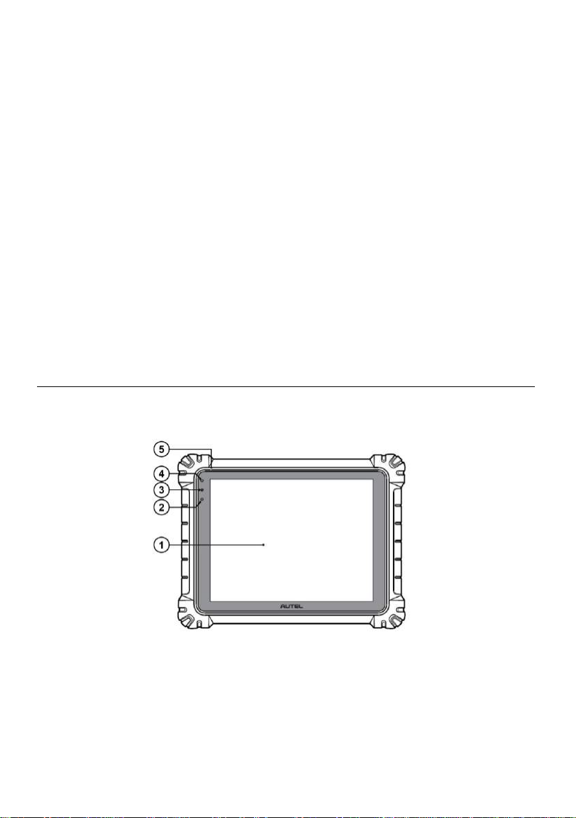
Figure 2-1 MaxiSys Tablet Front View
1. 12.9” TFT-LCD Capacitive Touch Screen
2. Ambient Light Sensor – detects ambient brightness.
3. Power LED - refer to Table 2-1 Power LED Description for details.
4. Front Camera
5. Built-in Microphone
3
Page 10
LED
Color
Description
Power
Green
Lights green when the Display Tablet is charging and
the battery level is above 90%.
Lights green when the Display Tablet is powered on
and the battery level is above 15%
Yellow
Lights yellow when the Display Tablet is charging and the
battery level is below 90%.
Red
Lights red when the Display Tablet is powered on and the
battery level is below 15%
Table 2-1 Power LED Description
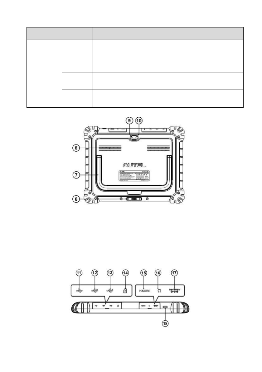
Figure 2-2 MaxiSys Tablet Back View
6. Docking Station Port
7. Collapsible Stand – extends from the back to allow hands-free viewing of the tablet
8. Speaker
9. Rear Camera
10. Camera Flash
11. Mini USB Port - cannot be used with the USB Port simultaneously
Figure 2-3 MaxiSys Tablet Top Side
4
Page 11
12. USB Port
13. USB Port
14. Mini SD Card Slot
15. HDMI (High-Definition Multimedia Interface) Port
16. Head Phone Jack
17. DC Power Supply Input Port
18. Lock/Power Button – long press to turn on and off the Display Tablet, or short press
to lock the screen.
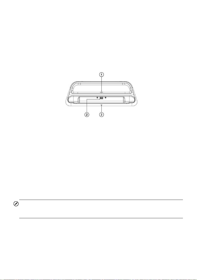
Figure 2-4 Docking Station
1. DC Power Port – connects to the AC/DC adapter for power supply
2. Charging Dock – holds the MaxiSys tablet while providing optimum visibility and
convenient charging
3. Status Indicator Light
The Indicator Light displays differently in response to the tablet status described below:
A. Green light – battery power of the tablet is sufficient (≥90%);
B. Yellow light – battery level is above 14% but below 90%;
C. Red light – battery level is below 14%;
NOTE
Please make sure no small metal or other conductive parts are around the Charging
Dock to avoid short circuit damage to the device.
2.1.2 Power Sources
The tablet can receive power from any of the following sources:
Internal Battery Pack
AC/DC Power Supply
5
Page 12

Item
Description
Operating System
Android 7.0
Processor
Samsung Exynos8895V 8-core Processor (2.3GHz
Quad-core Mongoose + 1.7GHz Quad-core A53)
Memory
4GB RAM & 256GB On-board Memory
Display
12.9 inch TFT-LCD with 2732 x 2048 resolution &
capacitive touch screen
Connectivity
WiFix2 (802.11 a/b/g/n/ac 2x2 MIMO)
BT v.2.1 + EDR
GPS
USB 2.0 (TWO USB HOST Type A, ONE USB
mini device)
SD Card (Support up to 64GB)
HDMI 2.0
Camera
Rear: 16 Megapixel, Autofocus with Flashlight
Front: 5.0 Megapixel
Vehicle Power
IMPORTANT
Please charge the battery with the ambient temperature between 0°C and 45°C. If
charge the battery when the temperature is out of range, the battery may catch on fire.
Internal Battery Pack
The tablet can be powered with the internal rechargeable battery, which if fully charged
can provide sufficient power for about 8 hours of continuous operation.
AC/DC Power Supply – using power adapter or docking station
The tablet can be powered from a wall socket using the AC/DC power adapter or the
docking station. The AC/DC power supply also charges the internal battery pack.
Vehicle Power
The tablet can be powered from the cigarette lighter or other suitable power port on the
test vehicle through a direct cable connection. The vehicle power cable connects to the
DC power supply port on the top side of the display unit.
2.1.3 Technical Specifications
Table 2-2 Tablet Specifications
6
Page 13

Item
Description
Sensors
Gravity Accelerometer, Ambient Light Sensor (ALS)
Audio
Input / Output
Microphone
Dual Speakers
3-Band 3.5 mm stereo/standard headset jack
Power and Battery
18000mAH 3.8 V lithium-polymer battery
Charging via 12 V AC/DC power supply with
the temperature between 0°C and 45°C
Input Voltage
12V/3A Adapter
Operating Temp.
0 to 50°C (32 to 122°F)
Storage Temp.
-20 to 60°C (-4 to 140°F)
Dimensions (WxHxD)
366.5 mm (14.43”) x 280.9 mm (11.06”) x 34 mm
(1.34”)
Weight
2.18kg (4.81 lb.)
Protocols
DoIP, PLC J2497, ISO-15765, SAE-J1939,
ISO-14229 UDS, SAE-J2411 Single Wire
Can(GMLAN), ISO-11898-2, ISO-11898-3,
SAE-J2819 (TP20), TP16, ISO-9141, ISO-14230,
SAE-J2610 (Chysler SCI), UART Echo Byte,
SAE-J2809 (Honda Diag-H), SAE-J2740 (GM
ALDL), SAE-J1567 (CCD BUS), Ford UBP, Nissan
DDL UART with Clock, BMW DS2, BMW DS1, SAE
J2819 (VAG KW81), KW82, SAE J1708, SAE-J1850
PWM (Ford SCP), SAE-J1850 VPW (GM Class2)
Item
Description
Input Voltage
DC/12V/3A
Operating Temperature
-10°C to +55°C (ambient)
Storage Temperature
-40°C to +85°C (ambient)
Dimensions (L x W x H)
396 x 136 x 54 (mm)
Weight
0.98kg (2.1605lb.)
Table 2-3 Docking Station Specifications
7
Page 14
2.2 MaxiFlash VCMI – Vehicle Communication and
Measurement Interface
2.2.1 Functional Description
Figure 2-5 VCMI Top View
1. Multimeter Jacks
2. USB Port
3. Hook
4. DC Power Supply Input Port
5. Power Button
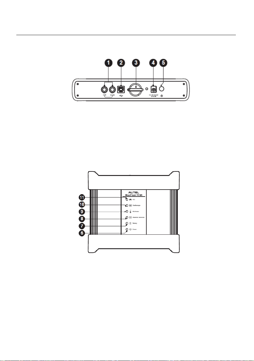
Figure 2-6 VCMI Front View
6. Power LED – refer to Table 2-4 Power LED Description for details
7. Battery LED - refer to Table 2-5 Battery LED Description for details
8. Signal Generator LED - lights green when operating in the signal generator mode
9. Multimeter LED - lights green when operating in the multimeter mode
10. Oscilloscope LED - lights green when operating in the oscilloscope mode and
flashes green when communicating
11. Vehicle LED - refer to Table 2-6 Vehicle LED Description for details
8
Page 15
LED
Color
Description
Power
Yellow
Lights yellow automatically at power up when VCMI is
self-testing.
Green
Lights solid green when powered on.
Red
Lights solid red when system failure occurs.
Flashes red when VCMI is upgrading.
LED
Color
Description
Battery
Green
Flashes green when VCMI is charging.
Lights solid green when fully charged or the battery
level is above 75%.
Yellow
Lights yellow when the battery level is above 25% but
below 75%.
IMPORTANT
Do not disconnect the programming device while the vehicle LED status light is on! If
the flash programming procedure is interrupted while the vehicle’s ECU is blank or only
partially programmed, the module may be unrecoverable.
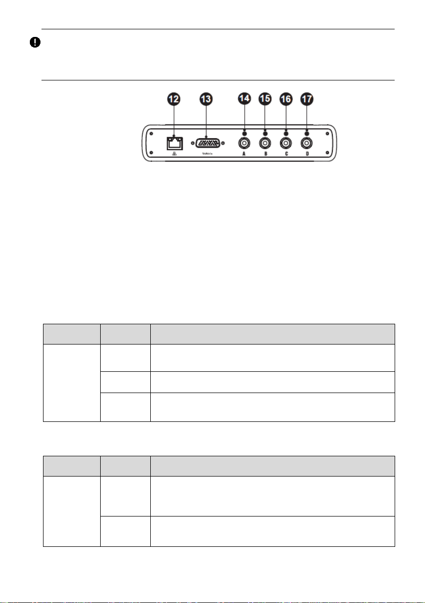
Figure 2-7 VCMI Bottom View
12. Ethernet Port
13. Vehicle Data Connector (DB26-Pin)
14. Input Channel A
15. Input Channel B
16. Input Channel C
17. Input Channel D
Table 2-4 Power LED Description
Table 2-5 Battery LED Description
9
Page 16

LED
Color
Description
Red
Lights red when the battery level is above 10% but
below 25%.
Flashes red when the battery level is below 10%.
LED
Color
Description
Vehicle
Green
Lights solid green when connected via USB cable.
Flashes green when communicating.
Blue
Lights solid blue when connected via BT. Flashes blue
when communicating.
Cyan
(Blue/Green)
Lights solid cyan when connected via Wi-Fi. Flashes
cyan (blue/green) when communicating.
Magenta
(Blue/Red)
Lights solid magenta when connected via Internet cable.
Flashes magenta (blue/red) when communicating.
Communication Capability
Table 2-6 Vehicle LED Description
The Vehicle Communication and Measurement Interface supports BT, Wi-Fi and USB
communications. It can transmit vehicle data to the tablet with or without a physical
connection. In open areas, the working range of the transmitter through BT
communication is up to 328 feet (100 m). The working range of 2.4G Wi-Fi
communication is up to 328 feet (100 m) while 5G Wi-Fi is up to 164 feet (50 m). A
signal lost due to moving out of range automatically restores itself when the tablet unit
is brought closer to the VCMI unit.
Measurement Capability
The VCMI device is designed with the functions of multimeter, oscilloscope, signal
generator and OBD communication line inspection. The parameters such as voltage,
resistance, current, signal frequency, and voltage-time characteristic of the signal can
be measured and the results are displayed on the Display Tablet.
Programming Capability
The VCMI device is a D-PDU, SAE J2534-1 & RP1210 compliant PassThru
programming interface device. Using the updated OEM software, it is capable of
replacing the existing software/firmware in the Electronic Control Units (ECU),
programming new ECUs and fixing software-controlled drivability issues and emission
issues.
10
Page 17

Item
Description
Communications
BT V2.1 + EDR
USB 2.0
Wi-Fi 2.4G/5G
Ethernet
Wireless Frequency
2.4GHz/5GHz
Power and Battery
3750 mAh lithium-polymer battery
Charging via 12 V DC power supply
Operating Temp.
0°C to 50°C
Storage Temp.
-20°C to 60°C
Dimensions (L x W x H)
214 mm (8.43”) x 192 mm (7.56”) x 39 mm
(1.54”)
Weight
g ( lb.)
2.2.2 Power Sources
The VCMI device can receive power from the following sources:
Vehicle Power
AC/DC Power Supply
Built-in Battery Pack
Vehicle Power
The VCMI device operates on 12/24 Volt vehicle power, which it receives through the
vehicle data connection port. The device powers on whenever it is connected to an
OBD II/EOBD compliant data link connector (DLC). For non OBD II/EOBD compliant
vehicles, the device can be powered from a cigarette lighter or other suitable power port
on the test vehicle using the auxiliary power cable.
AC/DC Power Supply
The VCMI device can be powered from a wall socket using the AC/DC power adapter.
Built-in Battery Pack
The VCMI device can also be powered with its built-in 3750mAh battery pack.
2.2.3 Technical Specifications
Table 2-7 VCMI Specifications
NOTE
11
Page 18
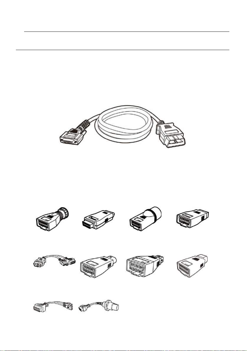
Benz-14
Chrysler-16
BMW-20
Nissan-14
Mitsubishi/Hyun
dai-12+16
Fiat-3
PSA-2
Mazda-17
VW/Audi-2+2
Benz-38
For additional information, please refer to the accompanied user manual for the VCMI
device.
2.3 Accessories Kit
2.3.1 Main Cable
The VCMI device can be powered through the Main Cable when connected to an OBD
II/EOBD compliant vehicle. The Main Cable connects the VCMI device to the vehicle’s
data link connector (DLC), through which the VCMI device can transmit vehicle data to
the tablet.
Figure 2-9 Main Cable – 1.5 m in length
2.3.2 OBD I Adapters
The OBD I adapters are for Non-OBD II vehicles. The adapter used depends on the
type of vehicle being tested. The most common adapters are shown (Some adapters
are optional, please contact your distributor for details).
12
Page 19

Docking Station
Provides power to the tablet.
Standard 2.0 USB Cable
Connects the tablet to the VCMI unit.
AC/DC External Power Adapter
Connects the tablet to the external DC power port for
power supply.
Cigarette Lighter
Provides power to the tablet or the VCMI device
through connection to the vehicle’s cigarette lighter
receptacle, as some non-OBD II vehicles cannot
provide power via the DLC connection.
Clipper Cable
Provides power to the tablet or the VCMI device
through connection to the vehicle’s battery.
Lighter Fuse x2
A safety device for the cigarette lighter.
2.3.3 Other Accessories
13
Page 20
3 Getting Started
Make sure the tablet has sufficient power or is connected to the external power supply
(see Power Sources on page 5).
3.1 Power Up
Long press the Lock/Power button on the top right side of the tablet to switch the unit on.
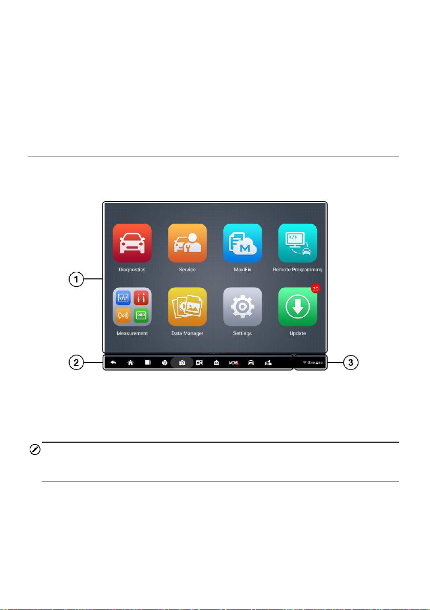
The system boots up and displays the MaxiSys Job Menu.
Figure 3-1 Sample MaxiSys Job Menu
1. Application Buttons
2. Locator and Navigation Buttons
3. Status Icons
NOTE
The screen is locked by default upon startup. It is recommended to lock the screen
when not in use to protect information in the system and conserve the power.
Almost all operations on the tablet are controlled through the touch screen. The touch
screen navigation is menu driven, which allows you to quickly locate the test procedure,
or data that you need, through a series of choices and questions. Detailed descriptions
of the menu structures are found in the chapters for each application.
14
Page 21
Name
Button
Description
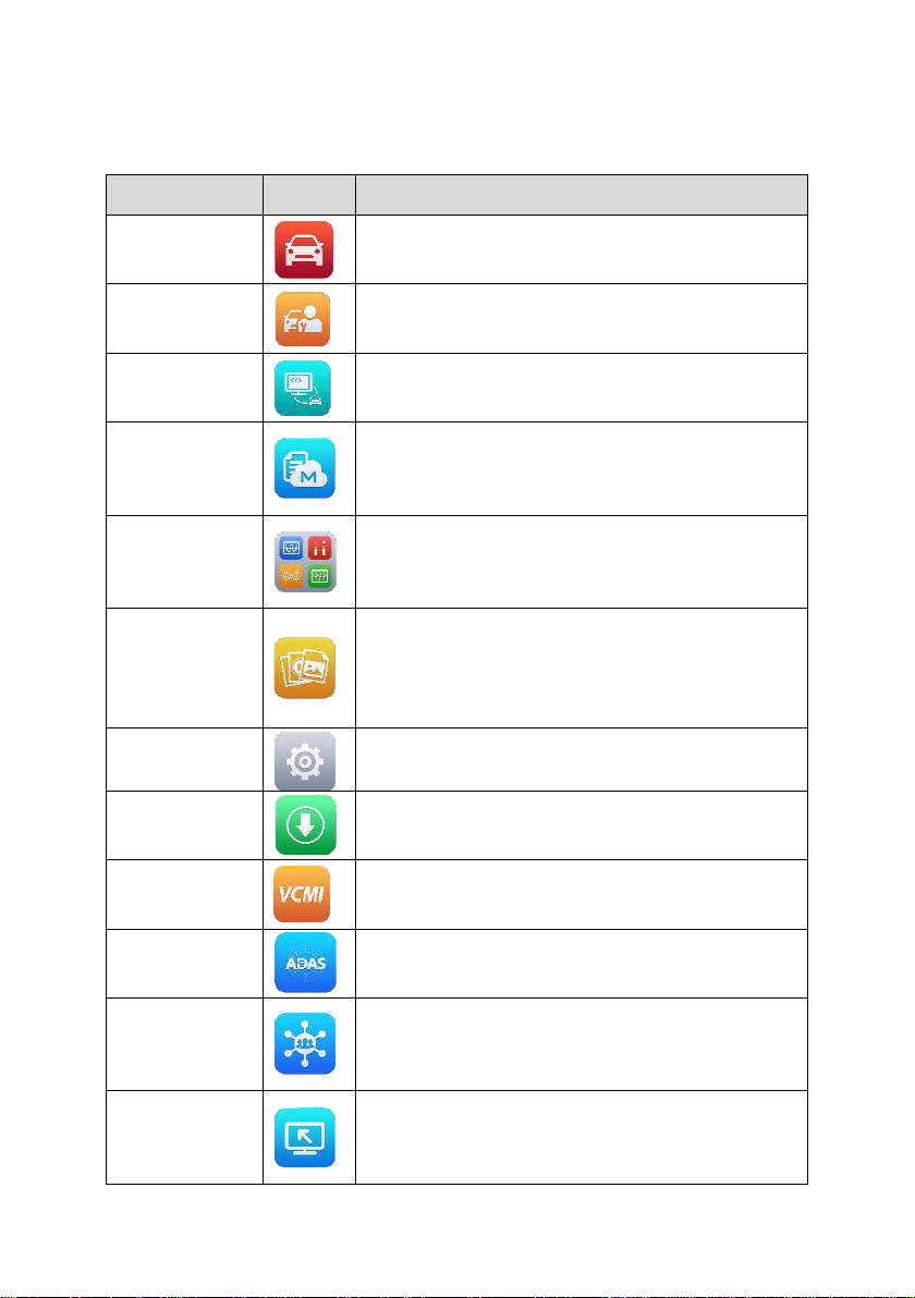
Diagnostics
Accesses the unit’s diagnostics functions. See
Diagnostics on page 20.
Service
Accesses special functions menu. See Service
on page 74.
Remote
Programming
Accesses remote programming request menu.
See Remote Programming on page 79.
MaxiFix
Provides the most compatible and abundant
repair techniques and diagnostics database. See
MaxiFix on page 88.
Measurement
Measures the parameters such as voltage,
resistance, current, and monitor signal activities.
See Measurement on page 103.
Data Manager
Accesses the organization system for saved data
files and to store workshop, consumer
information and vehicle test history. See Data
Manager on page 246.
Settings
Accesses the system settings menu and general
tablet menu. See Settings on page 255.
Update
Accesses system software update menu. See
Update on page 260.
VCMI
Manager
Accesses VCMI connection menu. See VCMI
Manager on page 262.
ADAS
Accesses ADAS introduction menu. See ADAS
on page 267.
Support
Synchronizes Autel’s online service base station
with the MaxiSys tablet. See Support on page
268.
Remote Desk
Configures your unit to receive remote support
using the TeamViewer application. See Remote
Desk on page 273.
3.1.1 Application Buttons
The table below briefly describes each of the applications in the MaxiSys system.
Table 3-1 Applications
15
Page 22
Name
Button
Description
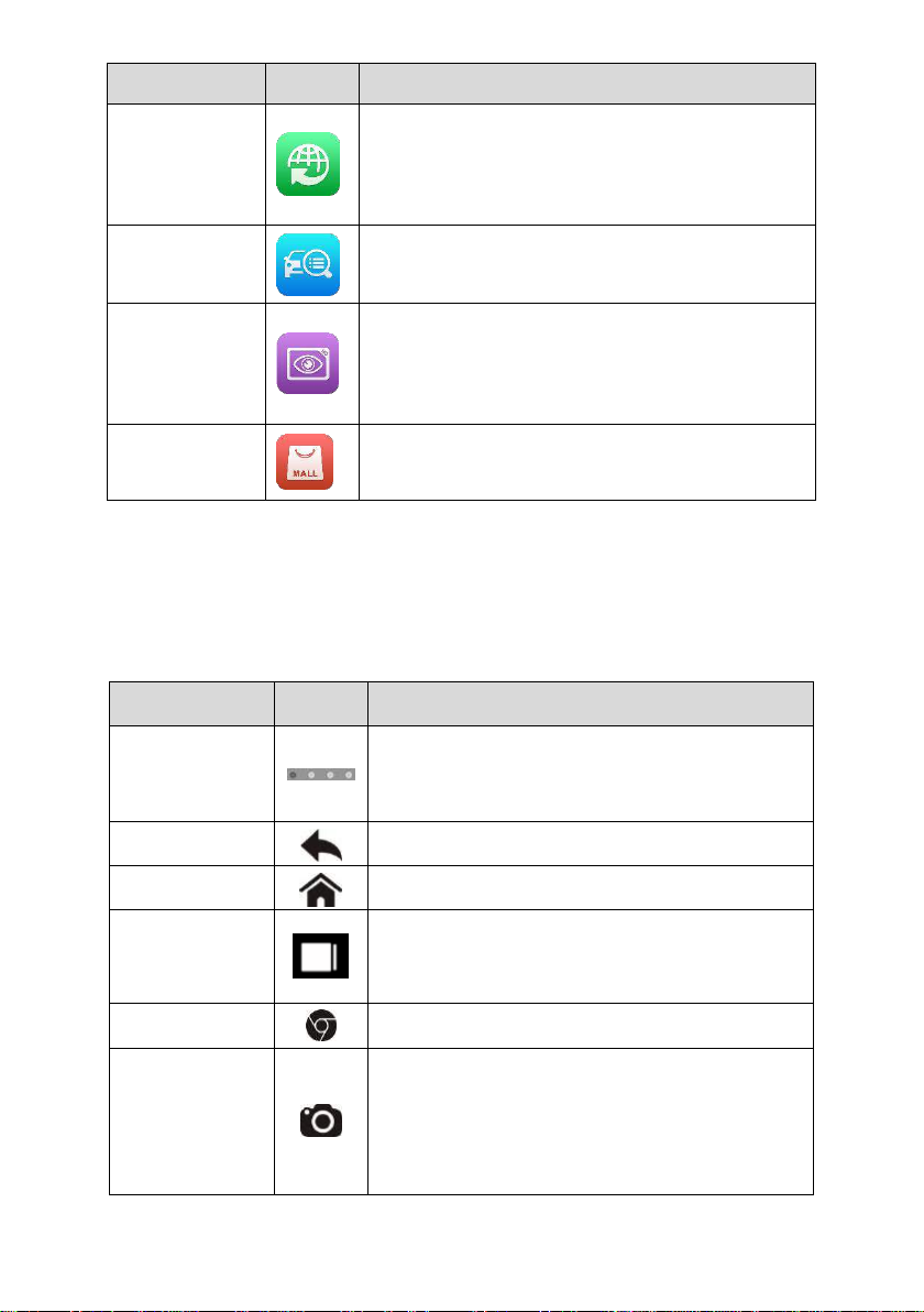
Quick Link
Provides associated website bookmarks to allow
quick access to product update, service, support
and other information. See Quick Link on page
275.
MaxiViewer
Provides a quick search for supported functions
and/or vehicles. See MaxiViewer on page 276.
MaxiVideo
Configures the unit to operate as a video scope
device by connecting to an Imager head cable for
close vehicle inspections. See MaxiVideo on
page 278.
MaxiMall
Repurchases the software that has expired. See
MaxiMall on page 285.
Name
Button
Description
Locator
Indicates the location of the screen. Swipe the
screen left or right to view the previous or next
screen.
Back
Returns to the previous screen.
Android Home
Returns to Android System’s Home screen.
Recent Apps
Displays a list of applications that are currently
working. Tap an app icon to launch. Remove an
app by swiping it to the right.
Browser
Launches the Chrome Internet browser.
Camera
Opens the camera with short press; takes and
saves screenshot image with long press. The
saved files are auto-stored in the Data Manager
application for later reviews. See Data Manager
on page 246.
3.1.2 Locator and Navigation Buttons
Operations of the Navigation buttons at the bottom of the screen are described in the
table below:
Table 3-2 Locator and Navigation Buttons
16
Page 23
Name
Button
Description
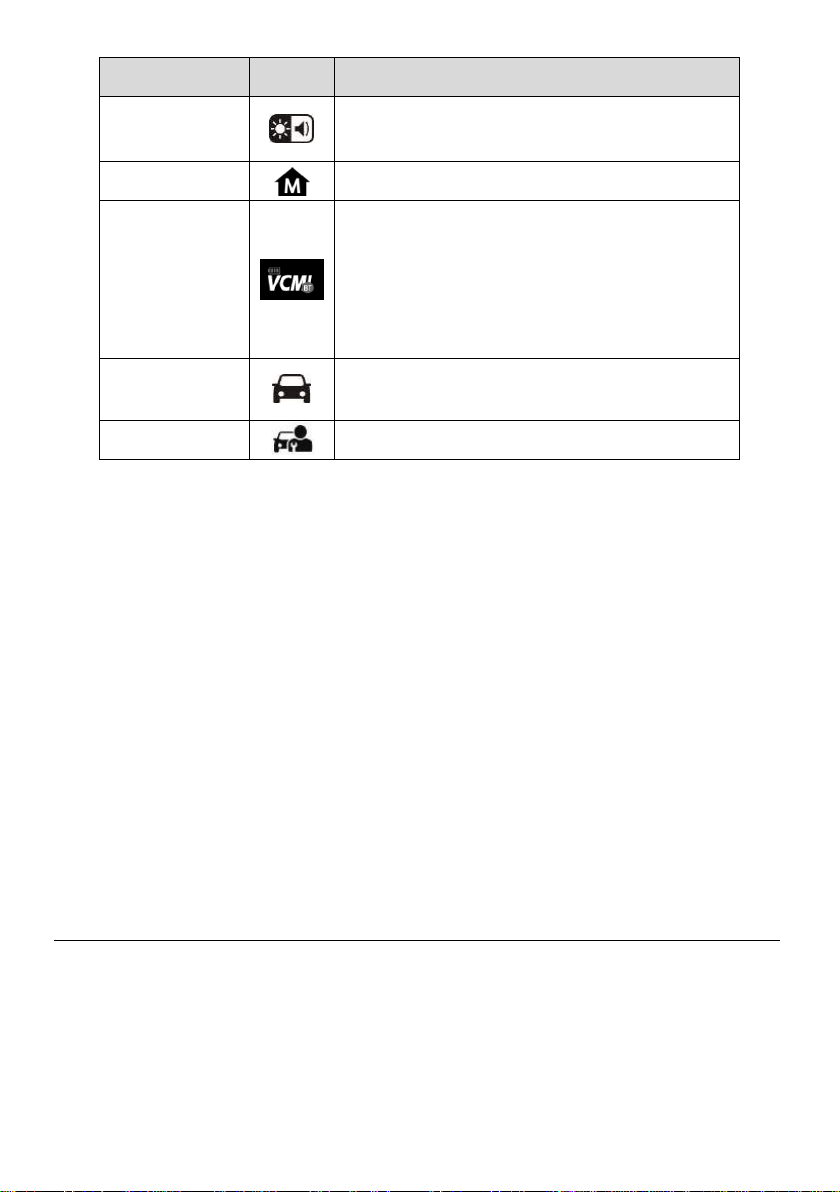
Display &
Sound
Adjusts the brightness of the screen and the
volume of the audio output.
MaxiSys Home
Returns to MaxiSys Job Menu.
VCMI
Opens the VCMI Manager application. A green
icon at the bottom right corner indicates the
VCMI device has communicated successfully, a
red cross icon will display if connection fails. The
battery status icon indicates how much power
the VCMI device remains.
MaxiSys
Shortcut
Returns to the Diagnostics screen.
Service
Returns to the Service screen.
To use the camera:
1. Tap the Camera button. The camera screen opens.
2. Focus the image to be captured in the view finder.
3. Tap the inner blue circle. The view finder now shows the captured picture and
auto-saves the taken photo.
4. Tap the thumbnail image on the top right corner of the screen to view the
stored image.
5. Tap the Back or Home button to exit the camera application.
Refer to Android documentation for additional information.
3.1.3 System Status Icons
These are the standard status icons of the Android operating system. Your MaxiSys
display tablet is a fully functional Android Pad. Refer to Android documentation for
additional information.
3.2 Power Down
All vehicle communications must be terminated before shutting down the tablet. A
warning message displays if a shutdown is attempted while the tablet is communicating
with the vehicle. Forcing a shut down while the tablet is communicating may lead to
ECM problems on some vehicles. Please exit the Diagnostics application before
shutting off the tablet.
To power down the MaxiSys tablet:
17
Page 24

1. Long press the Lock/Power Button.
2. Tap Power off option.
3. Tap OK.
3.2.1 Reboot System
In case of system crash, long press the Lock/Power button and tap Restart to reboot
the system.
3.3 Installing Computer Software
The MaxiSys Diagnostic Platform allows you to realize some of its functions on a
computer to enhance capabilities and improve user experience. To realize these
functions on a computer, you need to install certain software.
To install the MaxiSys Printer driver program:
1. Download the Maxi PC Suite from www.autel.com > Support & Updates >
Firmware & Downloads > Update Client, and install to your windows-based
computer.
2. Follow the pop-up instructions to install the Maxi PC Suit to your PC.
3. After the Maxi PC Suite installation, the printer driver program will be installed into
your PC automatically, which is call PC Link.
4. Click on Finish to complete the whole installation procedure.
3.3.1 Printing Operation
This section describes how to receive files from the MaxiSys Tablet and perform
printing through the windows-based computer:
To perform printing through the computer
1. Make sure the Display Tablet is connected to the computer network, either via
WiFi or LAN, before printing, See Printing Setting on page 256 for more
information.
2. Run the PC Link on the computer to open up the printer interface.
3. Click Test Print to make sure the printer is working successfully.
4. Tap the Print button on the toolbar displayed in various applications of the
MaxiSys system. A temporary file will be created and sent to the computer for
printing.
18
Page 25

5. The MaxiSys Printer will print the received file automatically when the Auto Print
option is checked.
If you need to print the document later, click the Open PDF file and select the
document, and double click the Print on the MaxiSys Printer interface to start the
printing.
NOTE
Make sure the computer installed with the Printing Services program is connected
to a printer.
19
Page 26

4 Diagnostics
The Diagnostics application can access the electronic control module of various vehicle
control systems, such as engine, transmission, antilock brake system (ABS), airbag
system (SRS) and more.
4.1 Establish Vehicle Communication and Selection
4.1.1 Establish Vehicle Communication
The Diagnostics operations require connecting the MaxiSys Ultra Diagnostic Platform
to the test vehicle through the VCMI device using the Main Cable and test adapters (for
non-OBD II vehicles). To establish proper vehicle communication to the tablet, you
need to perform the following steps:
1. Connect the VCMI device to the vehicle’s DLC for both communication and power
source.
2. Connect the VCMI device to the tablet via BT pairing, Wi-Fi or USB connection.
3. When the above steps are completed, check the VCMI navigation button at the
bottom bar on the screen, if a green BT, Wi-Fi or USB icon displays at the lower
right corner, the MaxiSys Ultra Diagnostic Platform is ready to start vehicle
diagnosis.
4.1.1.1 Vehicle Connection
The method used to connect the VCMI device to a vehicle’s DLC depends on the
vehicle’s configuration as follows:
A vehicle equipped with an On-board Diagnostics Two (OBD II) management
system supplies both communication and 12-volt power through a standardized
J-1962 DLC.
A vehicle not equipped with an OBD II management system supplies
communication through a DLC connection, and in some cases supplies 12-volt
power through the cigarette lighter receptacle or a connection to the vehicle
battery.
OBD II Vehicle Connection
This type of connection only requires the main cable without any additional adapter.
To connect to an OBD II vehicle
20
Page 27

1. Connect the main cable’s female adapter to the Vehicle Data Connector on the
VCMI device, and tighten the captive screws.
2. Connect the cable’s 16-pin male adapter to the vehicle’s DLC, which is
generally located under the vehicle dash.
NOTE
The vehicle’s DLC is not always located under the dash; refer to the user manual of the
test vehicle for additional connection information.
Non-OBD II Vehicle Connection
This type of connection requires both the main cable and a required OBD I adapter for
the specific vehicle being serviced.
There are three possible conditions for Non-OBD II vehicle connection:
DLC connection supplies both communication and power.
DLC connection supplies communication and power is to be supplied via the
cigarette lighter connection.
DLC connection supplies communication and power is to be supplied via
connection to the vehicle battery.
To connect to a Non-OBD II Vehicle
1. Connect the main cable’s female adapter to the Vehicle Data Connector on the
VCMI device, and tighten the captive screws.
2. Locate the required OBD I adapter and connect its 9-pin jack to the main
cable’s male adapter.
3. Connect the attached OBD I adapter to the vehicle’s DLC.
NOTE
Some adapters may have more than one adapter or may have test leads instead of an
adapter. Whatever the case, make the proper connection to the vehicle’s DLC as
required.
To connect the cigarette lighter
1. Plug the DC power connector of the cigarette lighter into the DC power supply
input port on the device.
2. Connect the male connector of the cigarette lighter into the vehicle’s cigarette
lighter receptacle.
To connect the clipper cable
1. Connect the tubular plug of the clipper cable to the male connector of the
cigarette lighter.
21
Page 28

Figure 4-1 Connection between Cigarette Lighter and Clipper Cable
2. Plug the DC power connector of the cigarette lighter into the DC power supply
input port of the VCMI device.
3. Connect the clipper cable to the vehicle’s battery.
NOTE
After the VCMI device is successfully connected to the vehicle, the Power LED on the
device illuminates, and a brief beep sound will be heard.
4.1.1.2 VCMI Connection
After the VCMI device is properly connected to the vehicle, the Power LED on the VCMI
device illuminates solid green, and is ready to establish communication with the tablet.
Coming with the MaxiSys Ultra tool kit, the VCMI device supports 3 communication
methods with the tablet: BT, Wi-Fi and USB.
Pairing Up via BT
In open areas, the working range for BT communication is about 328 feet (100 m); this
means you can perform vehicle diagnosis freely around the workshop with greater
convenience.
If you use more than one VCMI device to connect to the test vehicles when customers
are many, you can perform vehicle diagnosis on various vehicles conveniently, by
pairing the tablet separately to each of the VCMI devices connected to the different test
vehicles, via BT, without the need to repeat the plugging and unplugging procedure,
which is unavoidable through traditional wired connection, thus saves you more time
and provides more efficiency.
To pair up the tablet with the VCMI device via BT
1. If not already done, power up the tablet.
2. Select the VCMI Manager application from the MaxiSys Job Menu.
3. When the VCMI Manager application is opened, the device automatically
starts scanning for available VCMI devices around for BT pairing. The found
devices are listed in the Setting section on the right side of the screen.
22
Page 29

NOTE
If no VCMI device is found, this may indicate that the signal strength of the transmitter is
too weak to be detected. In this case try to get closer to the device, or reposition the
VCMI device, and remove all possible objects that may cause signal interference.
When done, tap the Scan button at the top right corner to start searching again.
4. Depending on the VCMI type you use, the device name may display as Maxi
suffixed with a serial number. Select the required device for pairing.
5. When pairing is successfully done, the connection status displayed to the right
of the device name is shown as Connected.
6. Wait for a few seconds, and the VCMI button on the system Navigation bar at
the bottom of the screen shall display a green circle BT icon, indicating the
tablet is connected to the VCMI device, and is ready to perform vehicle
diagnosis.
Refer to BT Pairing on page 264 for additional information.
Wi-Fi Connection
The VCMI device supports both 2.4GHz and 5GHz Wi-Fi connection. Please choose
2.4GHz or 5GHz Wi-Fi connection according to specific situations. In open areas, the
working range of 2.4G Wi-Fi communication is up to 328 feet (100 m) while 5G Wi-Fi is
up to 164 feet (50 m).
To pair up the tablet with the VCMI device via Wi-Fi
1. If not already done, power up the tablet.
2. Select the VCMI Manager application from the MaxiSys Job Menu.
3. When the VCMI Manager application is opened, the device automatically
starts scanning for available VCMI devices around for Wi-Fi connection. The
numbers of found VCMI devices are listed in the Setting section on the right
side of the screen.
4. Depending on the VCMI type you use, the device name may display as Maxi
suffixed with a serial number. Select the required device for connection.
5. When pairing is successfully done, the connection status is shown as
Connected.
6. Wait for a few seconds, and the VCMI button on the system Navigation bar at
the bottom of the screen shall display a green circle Wi-Fi icon, indicating the
tablet is connected to the VCMI device, and is ready to perform vehicle
diagnosis.
Refer to Wi-Fi Connection on page 263 for additional information.
USB Cable Connection
23
Page 30

The USB cable connection is a simple and quick way to establish communication
between the tablet and the VCMI device. After properly connecting the USB cable from
the tablet to the VCMI device, the VCMI navigation button at the bottom bar of the
screen shows a green tick icon in a few seconds, and the USB LED on the VCMI device
illuminates solid green light, indicating the connection between the devices is
successful.
The MaxiSys diagnostic platform is now ready to perform vehicle diagnosis.
NOTE
Since the USB connection provides the most stable and fastest communication, it is
highly recommended to apply this communication method when operating ECU
programming or coding. When all the two communication methods are applied at the
same time, the MaxiSys system will use the USB communication as the default priority.
4.1.1.3 No Communication Message
A. If the tablet is not connected to the VCMI device, an “Error” message displays. An
“Error” message indicates the tablet is not communicating with the VCMI device,
and so cannot gain access to the vehicle control module. In this case, you need to
do the following check-ups:
Check if the VCMI device is powered on.
In case of wireless connection, check if the network is configured correctly, or
if the right device has been paired.
If during the diagnosis process, communication is suddenly interrupted due to
the loss of signal, check if there are any objects that causes signal
interruption.
Check if the VCMI device is properly positioned. It is recommended to put the
VCMI device with the front side up.
Try standing closer to the VCMI device to obtain more stable signals, and
faster communication speed. In case of wired connection, check the cable
connection between the tablet and the VCMI device.
Check if the green LED on the VCMI device is illuminated for BT, Wi-Fi or
USB.
B. If the VCMI device is unable to establish a communication link, a prompt message
displays with check instructions. The following conditions are the possible causes
for this massage to display:
The VCMI device is unable to establish a communication link with the vehicle.
You’ve selected a system for testing that the vehicle is not equipped with.
There is a loose connection.
There is a blown vehicle fuse.
There is a wiring fault on the vehicle, or the data cable or adapter.
24
Page 31

Name
Button
Description
Home
Returns to the MaxiSys Job Menu.
VID Scan
Tap this button to open a dropdown list; tap Auto
Detect for auto VIN detection; tap Manual Input
to enter VIN code or license number manually.
There is a circuit fault in the data cable or adapter.
Incorrect vehicle identification was entered.
4.1.2 Getting Started
Prior to first use of the Diagnostics application, the VCMI device must be synchronized
with the tablet to establish a communication link. See VCMI Manager on page 262.
4.1.2.1 Vehicle Menu Layout
When the VCMI device is properly connected to the vehicle, and paired to the tablet,
the platform is ready to start vehicle diagnosis. Tap on the Diagnostics application
button on the MaxiSys Job Menu, the Vehicle Menu appears on the screen.
Figure 4-2 Sample Vehicle Menu Screen
1. Top Toolbar Buttons
2. Manufacturer Buttons
Top toolbar Buttons
The operations of the Toolbar buttons at the top of the screen are listed and described
in the table below:
Table 4-1 Top Toolbar Buttons
25
Page 32
Name
Button
Description
Tap Scan VID to scan the license number / VIN
code by camera.
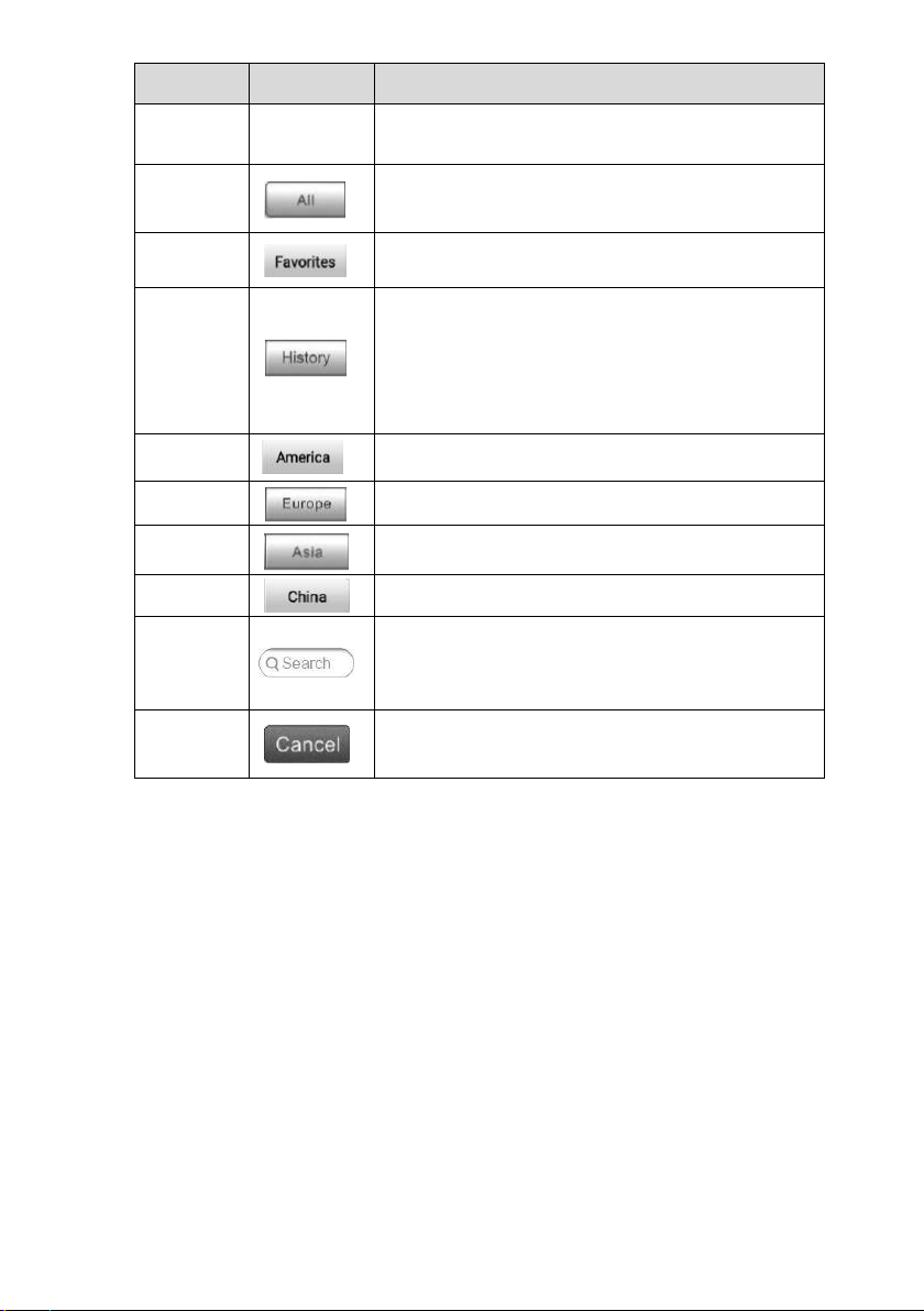
All
Displays all the vehicle makes in the vehicle
menu.
Favorites
Displays user’s favorite vehicle makes.
History
Displays the stored test vehicle history records.
This option provides you direct access to the
previously tested vehicle recorded during
previous test sessions. See Vehicle History on
page 247.
America
Displays the American vehicle menu.
Europe
Displays the European vehicle menu.
Asia
Displays the Asian vehicle menu.
China
Displays the Chinese vehicle menu.
Search
Touching this button opens the virtual keyboard,
allowing you to manually enter the specific
vehicle make required.
Cancel
Touching this button exits the search screen, or
cancels an operation.
Manufacturer Buttons
The Manufacturer buttons display the various vehicle logos and the brand names.
Select the required manufacturer button after the VCMI device is properly connected to
the test vehicle to start a diagnostic session.
4.1.3 Vehicle Identification
The MaxiSys diagnostic system supports five methods for Vehicle Identification.
1. Auto VIN Scan
2. Manual Input
3. Scan License / VIN
4. Manual Vehicle Selection
5. OBD Direct Entry
26
Page 33
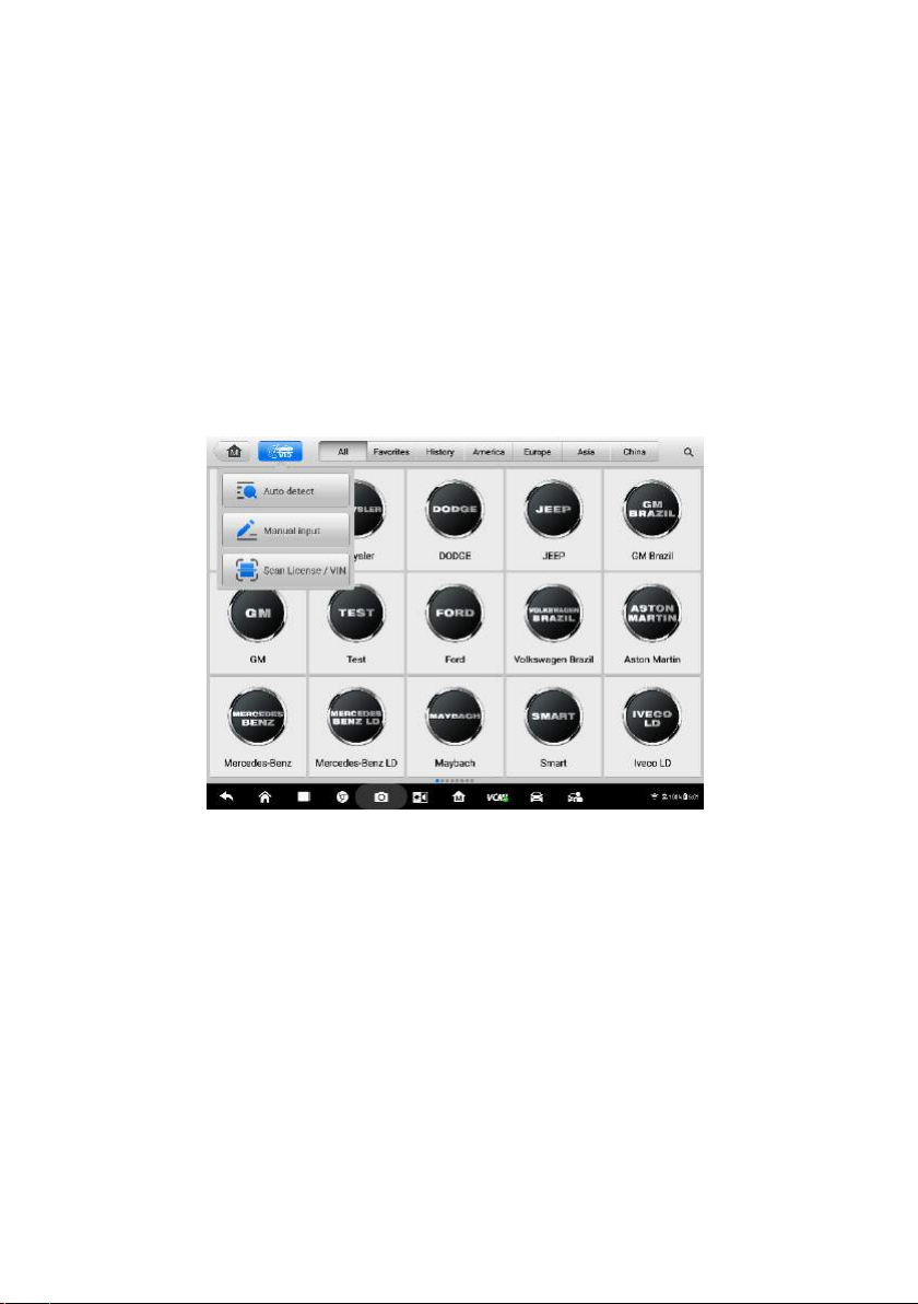
4.1.3.1 Auto VIN Scan
The MaxiSys diagnostic system features the latest VIN-based Auto VIN Scan function
to identify CAN vehicles in just one touch, which allows the technician to quickly detect
vehicles, scan all the diagnosable ECUs on every vehicle and run diagnostics on the
selected system.
To perform Auto VIN Scan
1. Tap the Diagnostics application button from the MaxiSys Job Menu. The
Vehicle Menu displays.
2. Tap the VID Scan button on the top toolbar.
3. Select Auto Detect. The tester starts VIN scanning on the vehicle’s ECU.
Once the test vehicle is successfully identified, the system will guide you to the
Vehicle Diagnostics screen directly.
Figure 4-3 Sample Auto Detect Screen
In some cases when users have selected the vehicle brand instead of performing Auto
VIN Scan in the first place, the system still provides an option for vehicle VIN scan.
27
Page 34
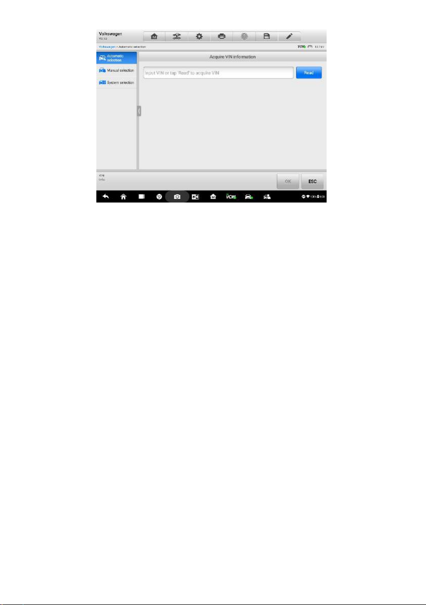
Figure 4-4 Sample Vehicle Selection Screen
Select Automatic Selection and the system will proceed to acquire VIN information
automatically or allow users to input the VIN manually.
4.1.3.2 Manual Input
For some vehicles that do not support the Auto VIN Scan function, the MaxiSys
diagnostic system allows you to enter the vehicle VIN manually, or simply take a photo
of the VIN sticker for quick vehicle identification.
To perform Manual Input
1. Tap the Diagnostics application button from the MaxiSys Job Menu. The
Vehicle Menu displays.
2. Tap the VID Scan button on the top toolbar.
3. Select Manual Input.
4. Tap the input box and enter the correct VIN code or license numbers.
28
Page 35
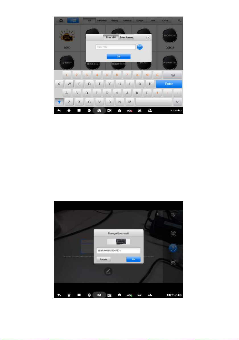
Figure 4-5 Sample Manual VIN Input
5. Tap OK. The vehicle will be identified in a few seconds, and once the matching
is successful, the system will guide you to the Vehicle Diagnostics screen
directly.
6. Tap Cancel to exit Manual Input.
4.1.3.3 Scan License / VIN
Tap Scan License / VIN in the dropdown list (Figure 4-3), the camera will be opened.
Then adjust the position of the device to align the license number or VIN Code with the
scanning window on the screen, the license number or VIN code will be scanned and
identified automatically, tap “OK”.
Figure 4-6 Sample Scan License / VIN Code 1
29
Page 36
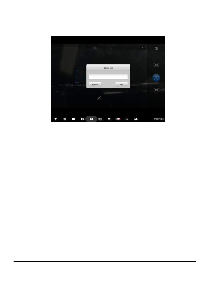
The vehicle information will be displayed on the tablet. If there are diagnostic records
before, the historical record and the vehicle information will be displayed. If there is no
related record, the vehicle number and model need to be inputted manually.
Figure 4-7 Sample Scan License / VIN Code 2
4.1.3.4 Manual Vehicle Selection
When the vehicle’s VIN is not automatically retrievable through the vehicle's ECU, or
the specific VIN is unknown, you can choose to select the vehicle manually.
Step-by-step Vehicle Selection
This mode of vehicle selection is menu driven; you simply follow the screen prompts
and make a series of choices. Each selection you make advances you to the next
screen. A Back button at the lower right corner of the screen returns you to the
previous screen. Exact procedures may vary somewhat by various vehicles being
serviced.
4.1.3.5 Alternative Vehicle Identification
Occasionally, you may identify a test vehicle that the tester does not recognize; the
database does not support, or has some unique characteristics that prevent it from
communicating with the tester through the normal channels. In these instances, you are
provided with the OBD direct entry, through which you can perform generic OBD II or
EOBD tests. See Generic OBD II Operations on page 56 for additional information.
4.2 Diagnostics Screen Layout
This section describes how to navigate the Diagnostics interface and select test
options.
30
Page 37
Name
Button
Description
Home
Returns to the MaxiSys Job Menu.
Vehicle
Swap
Exits the diagnostic session and returns to the
vehicle menu screen to select another vehicle for
testing.
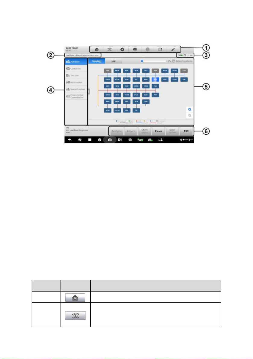
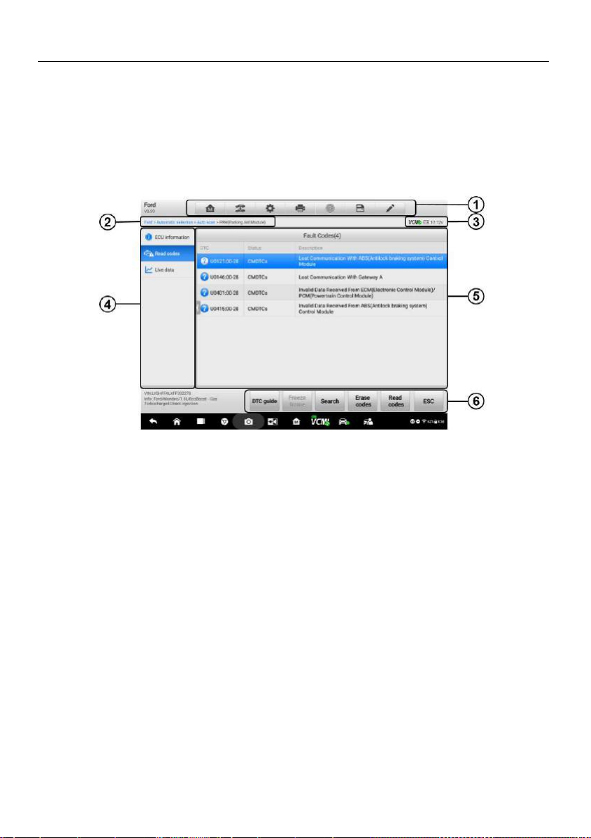
4.2.1 Diagnostics Screen Layout
The Diagnostics screens typically includes six sections.
Figure 4-8 Sample Diagnostics Screen
1. Diagnostics Toolbar
2. Current Directory Path
3. Status Information Bar
4. Navigation Bar
5. Main Section
6. Functional Buttons
Diagnostics Toolbar
The Diagnostics Toolbar contains buttons that allow you to print or save the displayed
data and perform other operations. The table below provides a brief description for the
operations of the Diagnostics toolbar buttons:
Table 4-2 Diagnostics Toolbar Buttons
31
Page 38
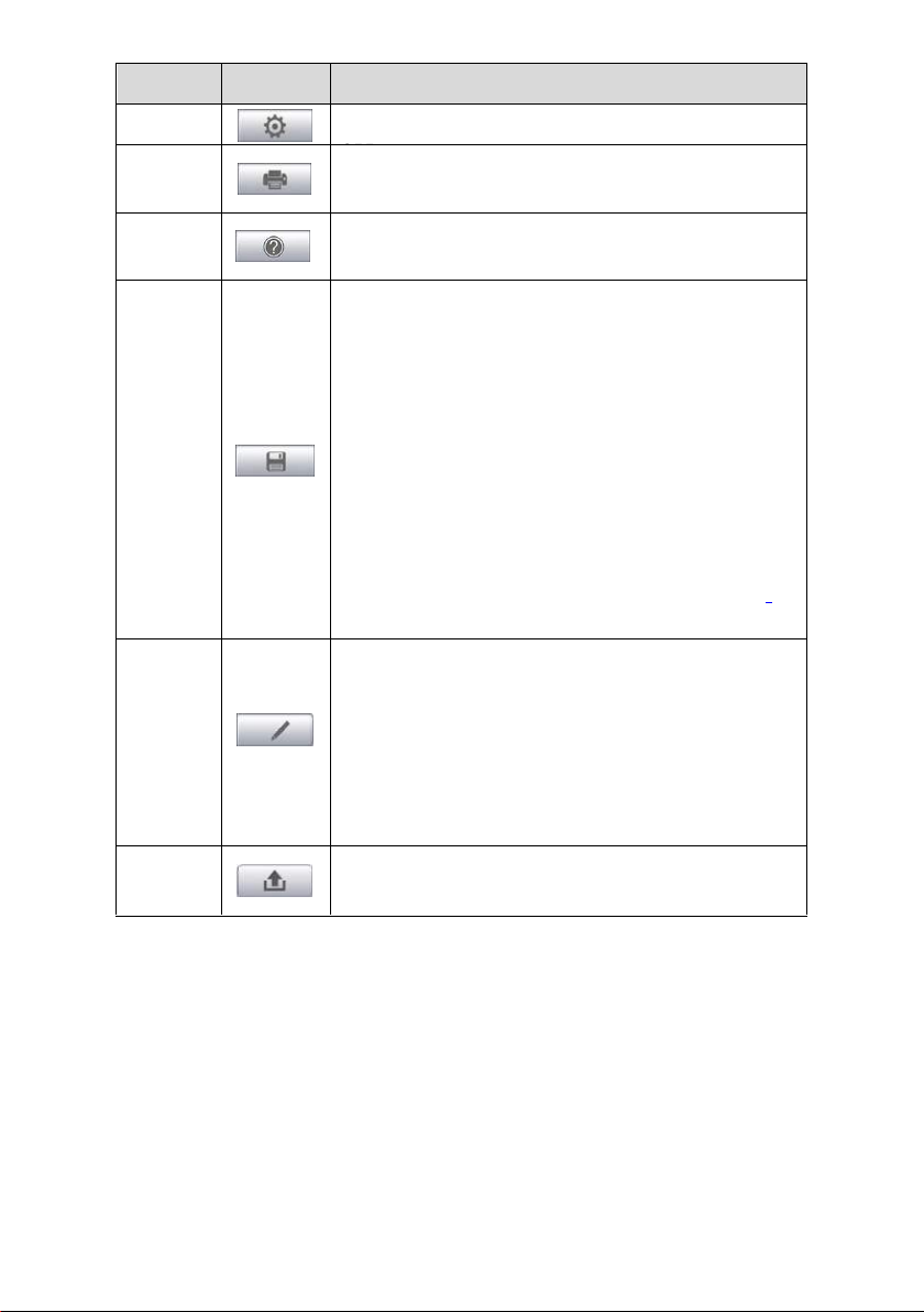
Name
Button
Description
Settings
Opens the setting screen. See Settings on page
Print
Saves and prints a copy of the displayed data. See
Print on page 256.
Help
Provides instructions or tips for operations of
various diagnostic functions.
Save
Taps it to open a submenu, on which there are 3
options available to save the displayed data.
Tap Save This Page to take a screenshot
image
Tap Save All Data to save a PDF file (mostly
used to save data that cover more than 1 page)
Tap Start Saving to record a video clip (only
available for recording Live Data or special
graph data)
All saved data are stored in the Data Manager
application for later reviews. See Data Manager on
page 246.
Data
Logging
Records the communication data and ECU
information of the test vehicle. The saved data can
be reported and sent to the technical center via the
Internet.
Go to the Support application to follow up the
processing progress, see Data Logging on page
271.
Send
Taps it to submit the Data Logging report to the
technical center via the Internet.
To print data in Diagnostics
1. Tap the Diagnostics application button from the MaxiSys Job Menu. The
Print button on the diagnostic toolbar is available throughout the whole
Diagnostics operations.
2. Tap Print and a drop-down menu appears.
a) Print This Page – prints a screenshot copy of the current screen.
b) Print All Data – prints a PDF copy of all displayed data.
3. A temporary file will be created and sent to the computer for printing.
4. When the file is transferred successfully, a confirmation message displays.
32
Page 39

NOTE
Make sure the tablet is connected to the computer network, either via Wi-Fi or LAN,
before printing. For more instructions on printing, see Print on page 256 for details.
To submit Data Logging reports in Diagnostics
1. Tap the Diagnostics application button from the MaxiSys Job Menu. The
pen-shaped Data Logging button on the diagnostic toolbar is available
throughout the whole Diagnostics operations.
2. Tap the Data Logging button to open a selection box. Select the abnormal
type(s) in the box. A blue tick indicates which option is selected. Tap OK to
continue.
3. A submission form will display to let you fill in the report information.
4. Tap the Send button in the upper right corner of the screen to submit the
report form via the Internet, a confirmation message displays when sending is
successful.
Status Information Bar
The Status Information Bar at the top of the Main Section displays the following items:
1. VCMI Icon – indicates the communication status between the tablet and the VCMI
device.
2. Battery Icon – indicates the battery status of the vehicle.
Main Section
The Main Section varies depending on the stage of operations which shows vehicle
identification selections, the main menu, test data, messages, instructions and other
diagnostic information.
The introductions below are of the two tab pages in the Main Section.
A. Topology Tab Page
The Topology Tab Page displays a system distribution diagram of the vehicle
control modules.
33
Page 40

Figure 4-9 Sample Topology Tab Page
Tap the modules to perform further diagnosis and other test activities. A Function
Menu screen (Figure 4-11) shall then display.
B. List Tab Page
Column 1 – displays the system numbers.
Column 2 – displays the scanned systems.
Column 3 – displays the diagnostic marks indicating different conditions of the test
result.
-!-: Indicates that the scanned system may not support the code reading
function, or there is a communication error between the tester and the control
system.
-?-: Indicates that the vehicle control system has been detected, but the
tester cannot accurately locate it.
Fault | #: Indicates there is/are detected fault code(s) present; “#” indicates
the number of the detected faults.
Pass | No Fault: Indicates the system has passed the scanning process
and no fault has been detected.
Not Scanned: Indicates the system has not been scanned.
No Response: Indicates the system has not received a response.
34
Page 41

Name
Description
Report
Displays the diagnostic data in the report form.
Quick Erase
Erases DTC records and other data from the ECM.
Fault Scan
Scans vehicle system modules.
Pause
Pauses the scanning process.
Enter System
Enters the ECU system.
ESC
Returns to the previous screen or exit Auto Scan.
Figure 4-10 Sample List Tab Page
Functional Buttons
The displayed Functional Buttons at the bottom of the screen vary by the stage of
operations. They can be used to navigate, save or clear the diagnostic data, exit
scanning as well as make other functional controls. The functions of these buttons will
be introduced respectively in the following sections of the corresponding test
operations.
The table below provides a brief description of the Functional Buttons’ operations in
Auto Scan:
Table 4-3 Functional Buttons in Diagnostics Screen
Select one of the system modules from the Topology or List, and tap Enter System to
enter the specific system functions
35
Page 42

NOTE
With the diagnostic toolbar hovering at the top of the screen throughout the whole
diagnostic procedures, you can perform various operations on the diagnostic
information at any time, such as printing and saving the displayed data, obtaining help
information, or performing data logging.
Figure 4-11 Sample Function Menu Screen
The options vary slightly for different vehicles. The function menu may include:
ECU Information – provides the retrieved ECU information in detail. Selecting
opens an information screen.
Read Codes – displays detailed information of DTC records retrieved from the
vehicle control module.
Erase Codes – erases DTC records and other data from the ECM.
Live Data – retrieves and displays live data and parameters from the vehicle’s
ECU.
Active Test – provides specific subsystem and component tests. This selection
may appear as Actuators, Actuator Test, or Function Tests and the tests options
vary depending on the manufacturer and model.
Control Unit - This option allows you to manually locate a required control system
for testing through a series of choices. Simply follow the menu driven procedure,
and make proper selection each time; the program will guide you to the diagnostic
function menu after you complete the choices.
36
Page 43

Figure 4-12 Sample Control Unit Screen
Special Functions – provides component adaptation or variant coding functions
for custom configurations, and allows you to reprogram adaptive values for certain
components after making repairs. Depending on the test vehicle, this section may
appear as Idle Learn, CKP Variation Learn, Engine Oil Life Reset, Fuel Trim Reset
or something similar.
Screen Messages
Screen messages appear when additional input is needed before proceeding. There
are mainly three types of on-screen messages as to their purposes: Confirmation,
Warning, and Error.
Confirmation Messages
This type of messages usually displays as an “Information” screen, which appears
when you are about to perform an action that cannot be reversed or when an action has
been initiated and your confirmation is needed to continue.
When a user-response is not required to continue, the message displays briefly before
automatically disappearing.
Warning Messages
This type of messages appears when completing the selected action may result in an
irreversible change or loss of data. A typical example is the “Erase Codes” message.
Error Messages
Error messages appear when a systemic or procedural error has occurred. Possible
errors include cable disconnection and communication interruption due to certain
reasons.
37
Page 44

4.2.2 Making Selections
The Diagnostics application is a menu-driven program that presents a series of choices
one at a time. As you select from a menu, the next menu in the series displays. Each
selection narrows the focus and leads to the desired test. Use your fingertip or the
stylus pen to make menu selections.
4.3 Auto Scan
The Auto Scan function performs a comprehensive scanning over all the systems on
the vehicle’s ECU in order to locate fault systems and retrieve DTCs. Tap Fault Scan to
start. A system which has passed scanning with no fault is shown in green font;
whereas a system that proves to be faulty in the scan is shown in orange.
To perform Auto Scan function
1. Tap the Diagnostics application button in the MaxiSys Job Menu. Choose the
corresponding vehicle information and enter the vehicle diagnostic page.
Figure 4-13 Sample Vehicle Selection Screen
2. The Topology tab page appears in the main section. Tap Fault Scan from the
bottom functional buttons to scan the vehicle system modules.
38
Page 45

Figure 4-14 Sample Auto Scan Screen 1
3. A system which has passed scanning with no fault is shown in green; whereas
a system that proves to be faulty in the scan is shown in orange.
Figure 4-15 Sample Auto Scan Screen 2
4.3.1 Test Plan
The Test Plan function intelligently calculates the priority of vehicle DTCs and guides
users to solve the problems step by step. This function is currently available for some
vehicles and more vehicles will be supported after subsequent updates.
To perform Test Plan function
1. Tap Test Plan from the bottom functional buttons, or tap Test Plan in the
39
Page 46

navigation bar to the left of the screen, then select Test Plan in the main
section.
Figure 4-16 Sample Test Plan Screen 1
2. A test plan appears showing recommended priority for each item. Items with
higher priority should be tested first.
Figure 4-17 Sample Test Plan Screen 2
4. Tap the button to test relative functions. Tap the button to see the
system information in detail and tap again to fold it.
40
Page 47

Figure 4 18 Sample Test Plan Screen 3
5. Press OK to continue.
Figure 4 19 Sample Test Plan Screen 4
6. Follow the instructions on the tablet to continue until the function is executed.
41
Page 48
4.4 Read and Erase Codes
4.4.1 Read Codes
This function retrieves and displays the DTCs from the vehicle’s control system. The
Read Codes screen varies for each vehicle being tested. For some vehicles, freeze
frame data can also be retrieved for viewing. The sample Read Codes screen displays
as below:
Figure 4-20 Sample Read Codes Screen
1. Diagnostics Toolbar – see Table 4-2 Diagnostics Toolbar Buttons on page 31 for
details.
2. Current Directory Path
3. Status Information Bar
4. Navigation Bar
5. Main Section
Column 1 – displays the retrieved codes from the vehicle.
Column 2 – indicates the status of the retrieved codes.
Column 3 – detailed descriptions for the retrieved codes.
6. Functional Buttons
DTC guide – tap to check related repair cases and help information.
Freeze Frame – only available when freeze frame data is available for viewing;
Selecting displays a data screen, which looks very similar to the Read Codes
interface, therefore same operation method may be applied.
42
Page 49

Search – tap it to search the selected DTC related information on the Internet.
Erase codes - after reading the retrieved codes from the vehicle and certain
repairs have been carried out, you can erase the codes from the vehicle using
this function.
Read codes - retrieves and displays the DTCs from the vehicle’s control
system. The Read Codes screen varies for each vehicle being tested.
ESC – tap it to return to the previous screen or exit the function.
4.1.2 Erase Codes
After reading the retrieved codes from the vehicle and certain repairs have been carried
out, you can erase the codes from the vehicle using this function. Before performing
this function, make sure the vehicle’s ignition key is in the ON (RUN) position with the
engine off.
To erase codes
1. Tap Erase Codes in the Function Menu.
2. A warning message displays to inform you of data loss when this function is
applied.
a) Tap Yes to continue. A confirming screen displays when the operation is
successfully done.
b) Tap No to exit.
3. Tap ESC on the confirming screen to exit Erase Codes.
4. Check the Read Codes function again to ensure the operation is successful.
4.5 Live Data
When this function is selected, the screen displays the data list for the selected module.
The data available for any control module varies from one vehicle to another. The
parameters display in the order that they are transmitted by the ECM, so expect
variation among vehicles.
Gesture scrolling allows you to quickly move through the data list. Touch the screen
and drag your finger up or down to reposition the parameters being displayed if the data
occupies more than one screen. The figure below displays a typical Live Data screen:
43
Page 50
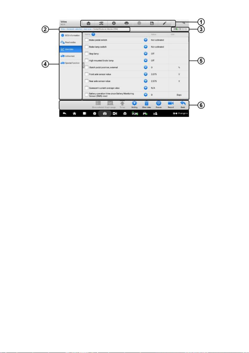
Figure 4-21 Sample Live Data Screen
1. Diagnostics Toolbar Buttons – see Table 4-2 Diagnostics Toolbar Buttons on page
31 for detailed descriptions of the operations for each button.
2. Current Directory Path
3. Status Information Bar
4. Navigation Bar
5. Main Section
Name Column – this column displays the parameter names.
a) Check Box – tap the check box to the left of a parameter name to select
the item. Tap the check box again to deselect it.
b) Drop-down Button – tap the drop-down button on the right side of the
parameter name to open a submenu, which provides optional modes in
which to display the data.
Value Column – displays the values of the parameter items.
Unit Column – displays the unit for the parameter values.
To change the Unit mode, tap the Setting button in the top toolbar and
select a required mode. See Unit on page 255.
Display Mode
There are four types of display modes available for data viewing, allowing you to view
various types of parameters in the most suitable way for better data check-ups.
44
Page 51

Tap the drop-down button on the right side of the parameter name to open a submenu.
There are 4 buttons to configure the data display mode, plus one Help button on the
right, active when additional information is available for your reference.
Each parameter item displays the selected mode independently.
Analog Gauge Mode – displays the parameters in gauge charts.
Text Mode – the default mode that displays the parameters in texts lists.
NOTE
Status parameters, such as a switch reading like ON, OFF, ACTIVE, and ABORT can
only be displayed in Text Mode. Whereas value parameters, such as a sensor reading,
can be displayed in both text mode and graph modes.
Waveform Graph Mode – displays the parameters in waveform graphs.
In this mode, three control buttons will appear on the right side of the parameter
item, allowing you to manipulate the display status.
Text Button – resumes Text Display Mode.
Scale Button – changes the scale values, which are displayed below the
waveform graph. There are four scales available: x1, x2, x4 and x8.
Zoom-in Button – taps once to display the selected data graph in full screen.
Digital Gauge Mode – displays the parameters in form of a digital gauge graph.
Full Screen Display – this option is only available in the waveform graph mode,
and mostly used in Graph Merge status for data comparison. There are three
control buttons available on the top right side of the screen under this mode.
Edit Button – tap to open an edit window, in which you can set the waveform
color and the line thickness displayed for the selected parameter item.
Scale Button – tap to change the scale values below the waveform graph.
There are four scales available: x1, x2, x4 and x8.
Zoom-out Button – tap to exit full screen display.
To edit the waveform color and line thickness in a data graph
1. Select 1 to 3 parameter items to display in Waveform Graph mode.
2. Tap the Zoom-in Button on the right side to display the data graph in full
screen.
3. Tap the Edit Button, and an edit window appears.
4. Select a parameter item from the left column.
45
Page 52

5. Select a desired sample color from the second column.
6. Select a desired sample line thickness from the right column.
7. Repeat step 4 to 6 to edit the waveform for each parameter item.
8. Tap Done to save the setting and exit, or tap Cancel to exit without saving.
6. Functional Buttons
The operations of all the available functional buttons on the Live Data screen are
described below:
Back – redirects you to the previous screen or exit the function.
Record – starts recording the retrieved live data; the recorded data is then stored
as a video clip in the Data Manager application for future reviews. This function can
be triggered automatically at preset threshold value or manually as you choose,
and the triggering mode and record duration can be configured in the Setting mode
of Live Data.
Freeze – displays the retrieved data in freeze mode.
Previous Frame – moves to the previous frame of frozen data.
Next Frame – moves to the next frame of frozen data.
Resume – this button displays when the Record or Freeze function is applied.
Tapping this button stops data recording, or exit freeze data mode, and resumes
normal data display mode.
Flag – this button displays when the Record function is applied. Tapping this button
sets flags for the recorded data at points wherever you choose, when playing back
the recorded video clip later in Data Manager, the preset flag will enable a popup to
allow notes to be input.
Clear Data – tap this button to clear all previously retrieved parameter values at a
cutting point whenever you choose.
To Top – moves a selected data item to the top of the list.
Graph Merge – tap this button to merge selected data graphs (for Waveform
Graph Mode only). This function is very useful when comparing different
parameters.
NOTE
This mode supports Graph Merge for 2 to 3 parameter items only, select 2 or 3 items
each time when making graph merge.
46
Page 53
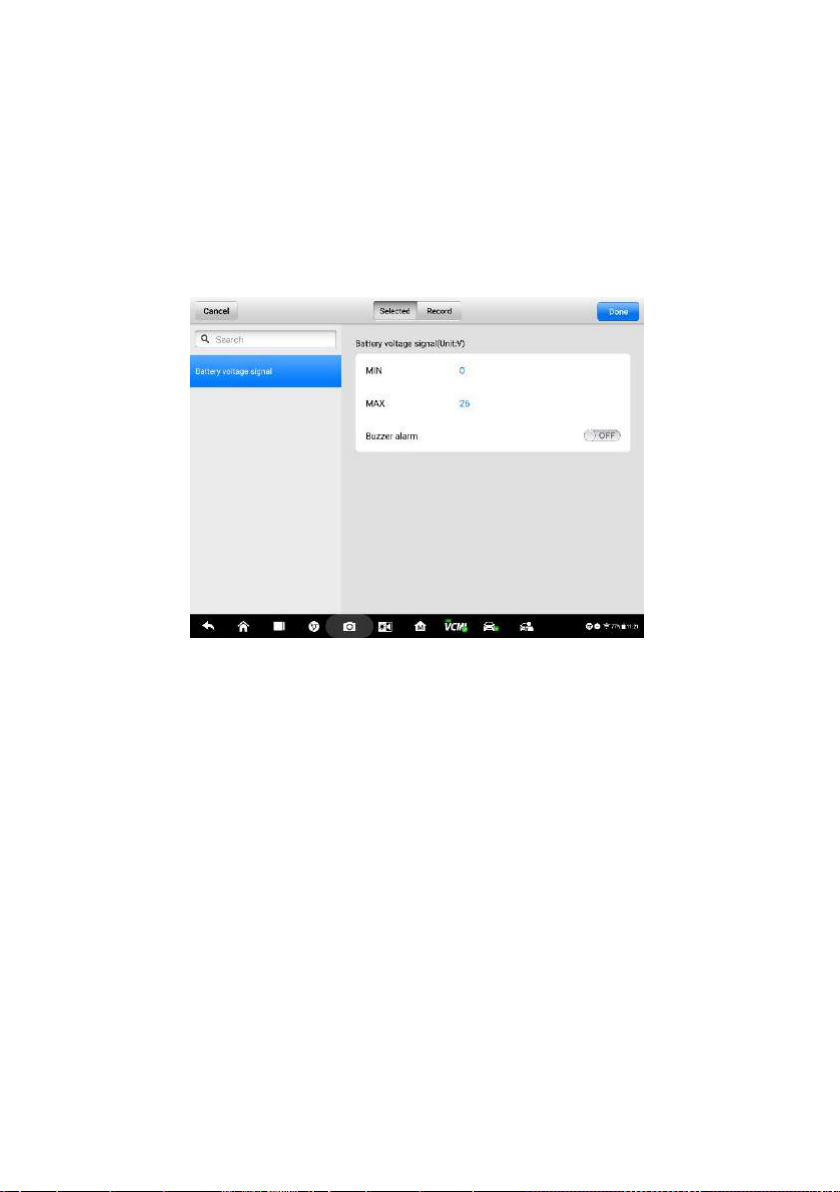
To cancel Graph Merge mode, tap the drop-down button on the right side of the
parameter name, and select a data display mode.
Show Selected/Show All – tap this button to exchange between the two
options; one displays the selected parameter items, the other displays all the
available items.
Setting – tap this button to open a setting screen, which allows you to set the
trigger mode, recording duration, and various threshold values for data
recording, and make other controls.
Figure 4-22 Sample Setting Mode in Live Data
There are four navigation buttons at the top of the Setting mode screen.
Selected Button – displays the configuration screen where you can set
the threshold values, an upper limit and a lower limit, for triggering the
buzzer alarm. This function is only applied to the Waveform Graph display
mode.
a) MIN – tap this button to open a virtual keyboard to enter the required
lower limit value.
b) MAX – tap this button to open a virtual keyboard to enter the required
upper limit value.
c) Buzzer Alarm – switches the alarm on and off. The alarm function
makes a beep sound as a reminder whenever the data reading
reaches the preset minimum or maximum point.
To set threshold limits for the parameter values
47
Page 54

1. Tap the Setting button at the bottom of the Live Data screen.
2. Tap the Selected navigation button.
3. Select a parameter item from the left column, or enter the item name
in the Search bar.
4. Tap the MIN button on the right side, and enter the required minimum
value.
5. Tap the MAX button on the right side, and enter the required
maximum value.
6. Tap the ON/OFF button on the right side of the Buzzer Alarm button
to turn it on or off.
7. Tap Done to save the setting and return to the Live Data screen; or
tap Cancel to exit without saving.
When the limits are successfully set, two horizontal lines appear on
each of the data graphs (when Waveform Graph Mode is applied) to
indicate the alarming point. The limit lines are shown in different
colors for distinction from the parameter waveforms.
Record – displays the configuration screen for Record Setting, where you
can set the trigger type, duration and trigger point for the data recording
function.
a) Trigger Type – sets the trigger mode for data recording, mainly of two
kinds: Manual and Auto. There are four options available:
1) Manual – allows you to manually start and stop data recording.
2) DTC – auto triggers data recording when any DTC is detected.
3) DTC Check Mode – auto triggers data recording when certain
pre-selected DTC types are detected.
4) Parameter – auto triggers data recording when any parameter
value reaches the preset threshold.
b) Duration – sets the recording time (for Auto trigger mode only).
c) Trigger Point – reserves a relative percentage of a record length
before the data recording start point for reference (for Auto trigger
mode only).
To perform setting for live data record
1. Tap the Setting functional button at the bottom of the Live Data
screen.
48
Page 55

2. Tap the Record navigation button.
3. Tap the button to the right of the Trigger Type bar and select the
required trigger mode.
4. Tap the button to the right of the Duration bar and select a length
of time.
5. Tap the button to the right of the Trigger Point bar and select a
relative percentage of a record length to be reserved before the data
recording start point.
6. Tap Done to save the setting and return to the Live Data screen; or
tap Cancel to exit without saving.
Done – confirms and saves the setting, and redirects you to the Live Data
screen.
Cancel – cancels the setting operation, and redirects you to the Live Data
screen.
4.6 Active Test
The Active Test function is used to access vehicle-specific subsystem and component
tests. Only available test vehicles, which vary by manufacturer, year, and model, are
displayed in the menu.
During an active test, the tester outputs commands to the ECU in order to drive the
actuators. This test determines the integrity of the system or parts by reading ECU data,
or by monitoring the operation of the actuators, such as switching a solenoid, relay, or
switch, between two operating states.
Selecting Active Test opens a menu of test options that varies by make and model.
Selecting a menu option activates the test. Follow all screen instructions while
performing tests. How and what information is presented on the screen vary according
to the type of test being performed. Some toggle and variable control tests display
Active Test Controls at the top of the screen with data stream information below, or vice
versa.
49
Page 56
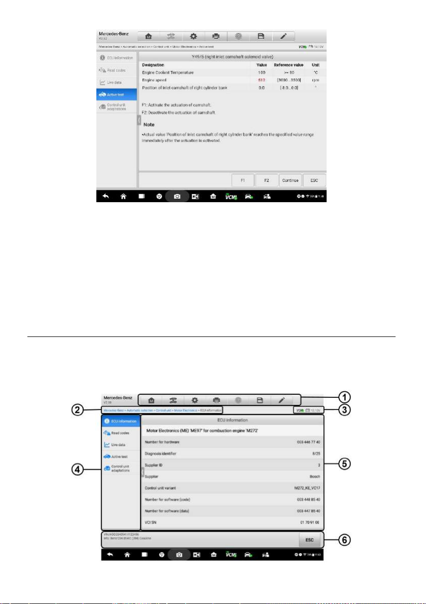
Figure 4-23 Sample Active Test Screen
The functional buttons in the lower right corner of the Active Test screen manipulate the
test signals. The operational instructions are displayed in the main section of the test
screen. Simply follow the on-screen instructions and make appropriate selections to
complete the tests. Each time an operation is successfully executed, message such as
“Command Finished”, or “Activation Successful” displays.
Tap the ESC functional button to exit the test when finished.
4.7 ECU Information
This function retrieves and displays the specific information for the tested control unit,
including unit type, version numbers and other specifications. The sample ECU
Information screen displays as below:
50
Page 57
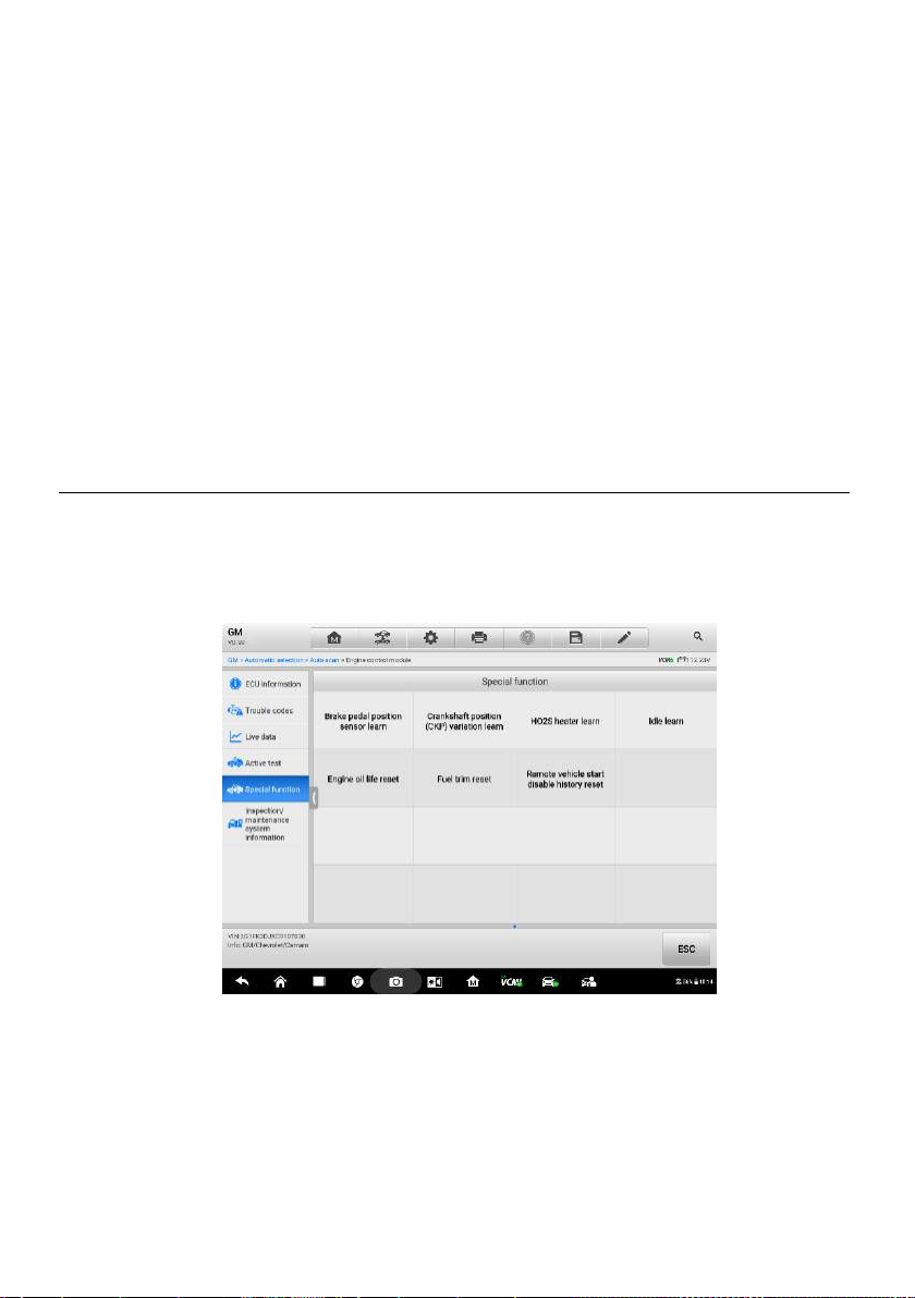
Figure 4-24 Sample ECU Information Screen
1. Diagnostics Toolbar Buttons – see Table 4-2 Diagnostics Toolbar Buttons on page
31 for detailed descriptions of the operations for each button.
2. Current Directory Path
3. Status Information Bar
4. Navigation Bar
5. Main Section – the left column displays the item names; the right column displays
the specifications or descriptions.
6. Functional Button – in this case, only a Back (or ESC) button is available; tap it to
exit after viewing.
4.8 Special Functions
These functions perform various component adaptations, allowing you to recalibrate or
configure certain components after making repairs or replacement.
The sample of the Special Function screen displays as below:
Figure 4-25 Sample Special Function Screen 1
Select one specific function, the screen displays as below:
51
Page 58

Figure 4-26 Sample Special Function Screen 2
List Tab Page:
Column 1 – displays the description of the function being performed or live data
corresponding to the special function
Column 2 – displays the execution status or value of the live data corresponding
to the special function, such as Completed, or Activated, etc.
Column 3 – displays the measurement units of the live data.
Tap the Learn button to perform the selected function and tap the ESC button to exit
the function.
4.9 Programming and Coding
Since the introduction of OBD II and leading up to modern Hybrids and EVs, hardware
and software technologies in cars have been advancing at an exponential rate. In-car
software is becoming one of the leading needs for service, and updating software may
be the only way to fix the following issues:
Drivability
Fuel Efficiency
Power Loss
Fault Codes
Durability of Mechanical Parts
The Programming and Coding function is used to re-flash the vehicle control modules,
which allows you to update the computer software of the vehicle to the latest version,
52
Page 59

as well as to reprogram adaptive data for certain components after making repairs or
replacements.
NOTE
The programming function applies only when the vehicle is connected with a VCMI or
J2534 programming device, which serves as a PassThru interface to establish
communication with and transfer data to the vehicle’s ECU.
Available programming or coding operations vary by test vehicle. Only the available
operations display in the tablet menu.
There are two general types of programming operations:
A. Coding – also known as Teach-in Program, or Component Adaptation, is used to
reprogram adaptive data for vehicle control modules after repairs or replacements
of vehicle parts.
B. Reprogramming Operations – downloads the latest version of software from the
online server database through Internet access (this procedure is done
automatically when the tablet is connected to the Internet, so there is no need to
check for software updates yourself), and reprograms the newest version into the
vehicle’s ECU.
NOTE
Ensure that the tablet is connected to a stable internet access before applying the ECU
programming function, so that the tablet is able to obtain access to the manufacturer’s
server for update service.
Selecting the Programming or Coding function opens a menu of operation options that
varies by make and model. Selecting a menu option either shows a programming
interface or opens another menu of additional choices. Follow all screen instructions
while performing the programming or coding operations. How and what information is
presented on the screen vary according to the type of operation being performed.
53
Page 60

4.9.1 Coding
Figure 4-27 Sample Coding Screen
The main section of the Coding screen displays a list of vehicle components and the
coding information that mainly consists of two parts:
1. All available systems for coding are displayed on the left side, and the coding data
or value on the right side.
2. The bottom line of the main section displays the functional buttons, which allows
you to manipulate the operation.
Check the vehicle condition and the coding information carefully, use the functional
button to edit Codes for the corresponding components, tap Send when you finish
editing all the items. When the operation is done, an execution status message such as
Completed, Finished or Successful, may display.
Tap the ESC button to exit the function.
4.9.2 Reprogramming Operation
Before reprogramming begins:
It is mandatory that Ultra tablet is connected to stable WiFi network.
Tablet must be connected to VCMI by USB.
Tablet battery must be fully charged during module programming. Connect tablet to
charger if needed.
Attach battery maintainer to vehicle battery to ensure steady 13-15 voltage is
54
Page 61

maintained.
If reprogramming a used module, it needs to be unlocked.
Do not quit the application during a module reprogramming process or will fail.
Typical reprogramming operations require you to input and validate VIN number first.
Tap the input box and enter the correct number, and the programming interface then
displays.
Figure 4-28 Sample Reprogramming Operation Screen
The main section of the reprogramming interface offers information of the hardware, the
current software version and the newest software versions to be programmed into the
control units.
A series of on-screen operational instructions will display to guide you through the
programming procedure.
Carefully read the on-screen information and follow the instruction to execute the
programming procedure.
4.9.3 Re-flash Errors
IMPORATANT
When reprogramming onboard, always make sure the vehicle battery is fully charged
and in good working condition. During reprogramming, the operation may fail if voltage
falls below the proper operation voltage. Sometimes a failed operation can be
recovered, but the failed reprogramming can also ruin the control module. We
recommend connecting an external battery maintainer to the vehicle to ensure steady
12-15 voltage is maintained and a successful operation.
55
Page 62

Occasionally a flash update procedure may not complete properly. Common causes of
flash errors include poor cable connections between the tablet, VCMI, and vehicle, the
vehicle ignition being switched off before the flash procedure is complete, or low vehicle
battery voltage.
If the process crashes, recheck all the cable connections to assure good
communications and initialize the flash procedure. The programming procedure will
automatically repeat if the previous operation does not succeed.
4.10 Generic OBD II Operations
A fast-access option for OBD II/EOBD vehicle diagnosis is available on the Vehicle
Menu screen. This option presents a quick way to check for DTCs, isolate the cause of
an illuminated malfunction indicator lamp (MIL), check monitor status prior to emissions
certification testing, verify repairs, and perform other emissions-related services. The
OBD direct access option is also used for testing OBD II/EOBD compliant vehicles that
are not included in the Diagnostics database. Functions of the diagnostics toolbar
buttons at the top of the screen are the same as those available for specific vehicle
diagnostics. See Table 4-2 Diagnostics Toolbar Buttons on page 31 for details.
General Procedure
To access the OBD II/EOBD diagnostics functions
1. Tap the Diagnostics application button in the MaxiSys Job Menu. The Vehicle
Menu displays.
2. Tap the EOBD button. There are two options to establish communication with
the vehicle.
Auto Scan – select it to establish communication using each protocol in
order to determine which one the vehicle is broadcasting on.
Protocol – select it to open a submenu of various protocols. A
communication protocol is a standardized way of data communication
between an ECM and a diagnostic tool. Global OBD may use several
different communication protocols.
3. Select a specific protocol if the Protocol option is selected. Wait for the OBD II
Diagnostic Menu to appear.
56
Page 63

Figure 4-29 Sample OBD II Diagnostic Menu
4. Select a function option to continue.
DTC & FFD
I/M Readiness
Live Data
O2 Sensor Monitor
On-Board Monitor
Component Test
Vehicle Information
Vehicle Status
NOTE
Some functions are supported only on certain vehicles.
Function Descriptions
This section describes the various functions of each diagnostic option:
DTC & FFD
When this function is selected, the screen displays a list of Stored Codes and Pending
Codes. When the Freeze Frame data of certain DTCs are available for viewing, a
snowflake button will display on the right side of the DTC item. The Erase Codes
function can be applied by tapping the functional button at the bottom of the screen.
57
Page 64
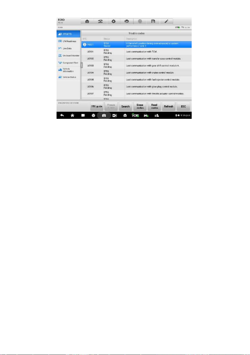
Figure 4-30 Sample DTC & FFD Screen
Stored Codes
Stored codes are emission-related DTCs from the ECM of the vehicle. OBD
II/EOBD Codes have a priority according to their emission severity, with
higher-priority codes overwriting lower-priority ones. The priority of the code
determines the illumination of the Malfunction Indicator Light (MIL) and the codes
erase procedure. Manufacturers rank codes differently, so expect to see
differences between vehicles.
Pending Codes
These are codes whose storing conditions have been met during the last drive
cycle, but need to be met on two or more consecutive drive cycles before the DTC
stored. The purpose of this service is to assist the service technician after a vehicle
repair when diagnostic information is cleared, by reporting test results after a single
driving cycle.
a) If a test fails during the driving cycle, the DTC associated is reported. If the
pending fault does not occur again within 40 to 80 warm-up cycles, the fault is
automatically cleared from memory.
b) Test results reported by this service do not necessarily indicate a faulty
component or system. If test results indicate another failure after additional
driving, a DTC is stored to indicate a faulty component or system, and the MIL
is illuminated.
Freeze Frame
In most cases the stored frame is the last DTC reported. Certain DTCs, those that
have a greater impact on vehicle emission, have a higher priority. In these cases,
58
Page 65

DTC of the highest priority is the one for which the freeze frame records are
retained. Freeze frame data includes a “snapshot” of critical parameter values at
the time the DTC is stored.
Erase Codes
This option is used to clear all emission-related diagnostic data such as, DTCs,
freeze frame data and specific manufacturer-enhanced data from the vehicle’s
ECM, and resets the I/M Readiness Monitor Status for all vehicle monitors to Not
Ready or Not Complete status.
A confirmation screen displays when the clear codes option is selected to prevent
accidental loss of data. Select Yes on the confirmation screen to continue, or No to
exit.
I/M Readiness
This function is used to check the readiness of the monitoring system. It is an excellent
function to use prior to having a vehicle inspected for compliance to a state emissions
program. Selecting I/M Readiness opens a submenu with two choices:
Since DTCs Cleared – displays the status of monitors since the last time the DTCs
are erased.
This Driving Cycle – displays the status of monitors since the beginning of the
current drive cycle.
Live Data
This function enables the display of real-time PID data from the ECU. Displayed data
includes analog and digital input and output, and system status information broadcast
in the vehicle data stream.
Live data can be displayed in various modes, see 4.5 Live Data on page 43 for detailed
information.
O2 Sensor Monitor
This function allows retrieval and review of recent O2 sensor monitor test results stored
on the vehicle’s on-board computer.
The O2 Sensor Monitor test function is not supported by vehicles that communicate
using a controller area network (CAN). For O2 Sensor Monitor tests results of
CAN-equipped vehicles, refer to On-Board Monitor.
On-Board Monitor
This function allows you to view the results of On-Board Monitor tests. The tests are
useful after the service when a vehicle’s control module memory is already erased.
59
Page 66

Component Test
This function enables dual-direction control of the ECM so that the diagnostic tool can
transmit control commands to operate the vehicle systems. This function is useful in
determining how well the ECM responds to a command.
Vehicle Information
This function enables the display of the vehicle identification number (VIN), calibration
identification number, calibration verification number (CVN), and other information of
the test vehicle.
Vehicle Status
This function service to check the current condition of the vehicle, such as the
communication protocols of OBD II modules, retrieved codes amount, and status of the
Malfunction Indicator Light (MIL).
4.11 Diagnostic Report
Pre-Scan and Post-Scan
To perform the pre-scan and post-scan functions:
1. Auto SCAN the Vehicle - the Auto VID function can instantly identify all vehicle
information. All available modules in all systems will be scanned automatically.
Then DTCs and code details will be listed.
2. Print Pre-SCAN Report - vehicle pictures can be attached to SCAN report. The
report file can be generated and submitted. The report is customized with shop
and vehicle information.
3. Repair Vehicle - creates efficient repair plan from the start.
4. Auto SCAN Repaired Vehicle - ensures no new faults were created during repair
and no DTCs are present at completion.
5. Print Post-SCAN Report - proves all DTCs on Pre-SCAN report are fixed.
Diagnostic Report PDF
The diagnostic report can be reviewed, saved, and printed in the following interfaces.
a) Via the History function:
Enter the Diagnosis main page, and tap History in the Top Toolbar.
60
Page 67
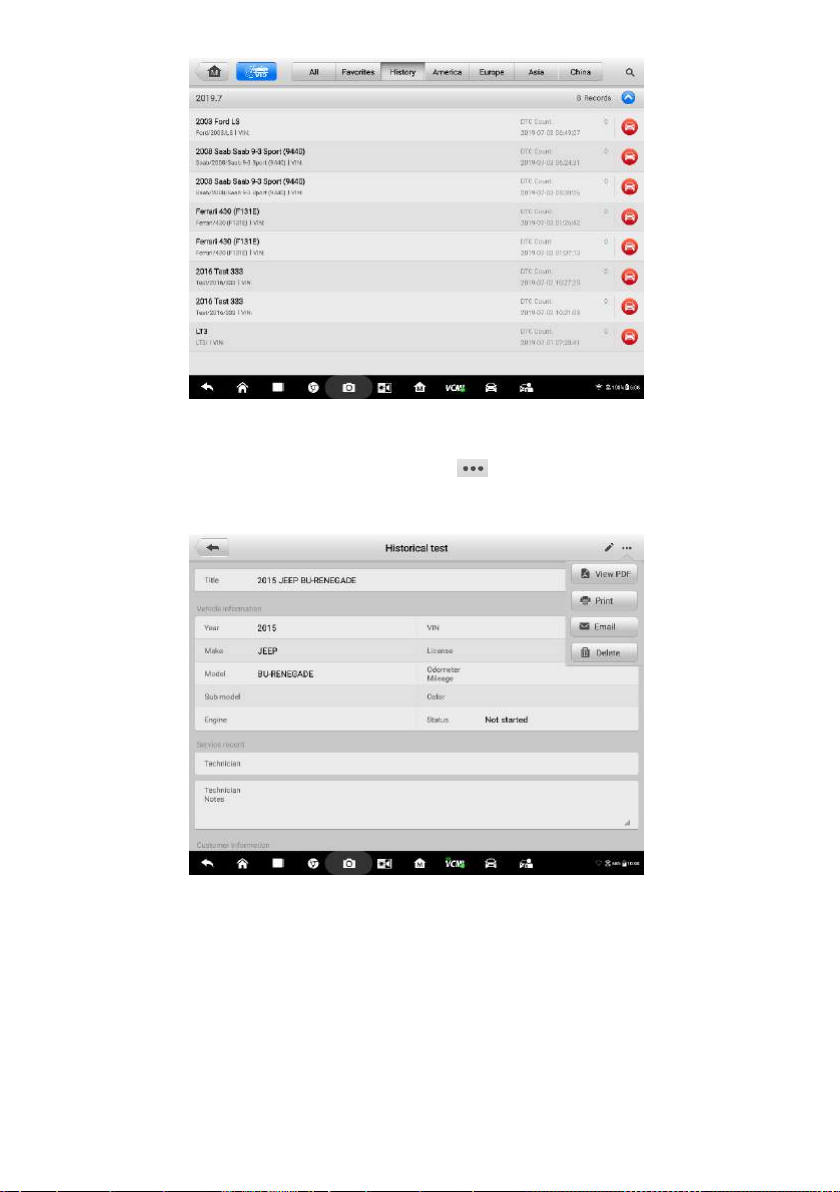
Figure 4-31 Sample History Screen
Select a history record, and tap the button in the upper right corner to
view, print, email or delete the PDF document.
Figure 4-32 Sample Historical Test Screen
b) Via the Auto Scan function:
Enter the Auto Scan page and tap Fault Scan in the Functional Button Bar at
the bottom of the screen.
61
Page 68
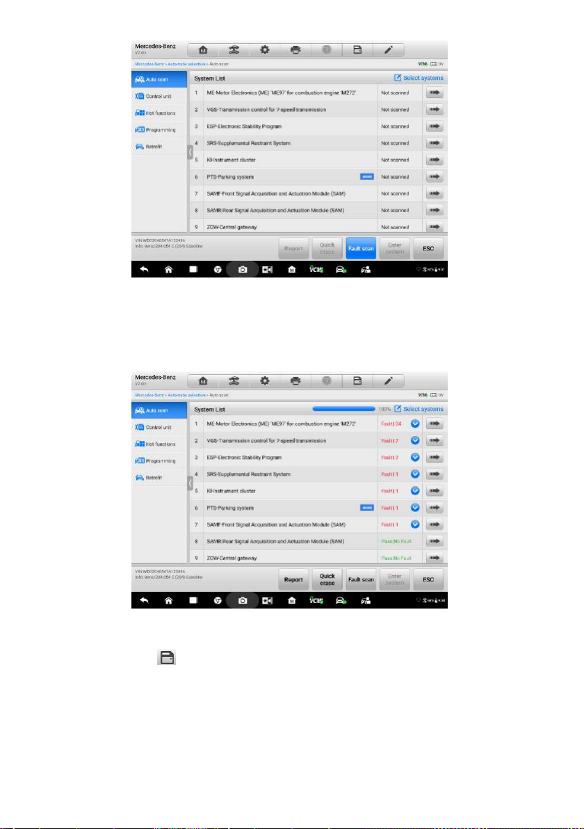
Figure 4-33 Sample Auto Scan Screen 1
When the system scan is completed, tap Report in the Functional Button Bar
at the bottom of the screen.
Figure 4-34 Sample Auto Scan Screen 2
Tap the button in the Diagnostics Toolbar, and select Save all data to
save the PDF document or select Save this page to save the screen shot of
the current page.
62
Page 69
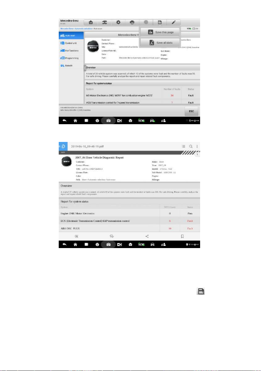
Figure 4-35 Sample Auto Scan Screen 3
Figure 4-36 Sample PDF Document Screen
c) Via the functions on the Navigation Bar:
The diagnostic report can also be reviewed through Auto scan, Read codes,
Live data, and Active test, etc. functions page. Tap the button in the
Diagnostics Toolbar, and select Save all data to save the PDF document or
select Save this page to save the screen shot of the current page.
63
Page 70
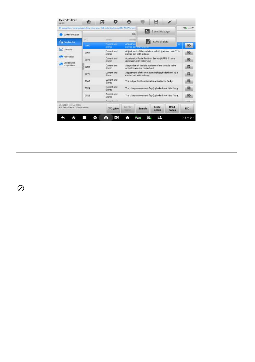
Figure 4-37 Sample Read Codes Screen
4.12 Exit Diagnostics
The Diagnostics application operates as long as communication with the vehicle is still
active. You must exit the diagnostics operation interface to stop all communications
with the vehicle before closing the Diagnostics application.
NOTE
Damage to the vehicle electronic control module (ECM) may occur if communication is
disrupted. Make sure that all forms of connection, such as data cable, USB cable, and
wireless or wired network, are properly connected throughout the test. Exit all interfaces
before disconnecting the test cable and power supply.
To exit the Diagnostics application
1. On an active diagnostic screen, tap the Back or ESC functional button to exit
a diagnostic session step-by-step; Or
2. Tap the Vehicle Swap button in the diagnostics toolbar to return to the Vehicle
Menu screen.
3. On the vehicle menu screen, tap the Home button in the top toolbar; or tap the
Back button in the navigation bar at the bottom of the screen. Or
4. Tap the Home button in the diagnostics toolbar to exit the application directly
and return to the MaxiSys Job Menu.
Now, the Diagnostics application is no longer communicating with the vehicle and it is
safe to open other MaxiSys applications, or exit the MaxiSys Diagnostic System and
return to the Android System’s Home screen.
64
Page 71

5 Repair Assist
Repair Assist is a specific fault code analysis function, with which you can access the
most comprehensive and the latest code-specific data, tests information, real repairing
cases and relevant fixes. It is finely assembled based on real shop repair orders and
industry professionals.
Apart from that, in order to ensure the accuracy and reliability of the Repair Assist, a
huge database has been built. Repair Assist adopts the scientific data cloud computing
technology to match the specific fault code with the exact model of various vehicle
brands. And the data has been verified strictly by maintenance experts.
The following are main parts of the code data contained in Repair Assist:
1. Technical Service Bulletin (OEM Information)
2. Frequency of Occurrence
3. Troubleshooting
4. Real Fixes
5. Relevant Repair Information
6. Recommended Cases
5.1 Access the System
Before starting Repair Assist, please ensure that the vehicle communication has been
established properly. Namely, connect the MaxiSys Ultra Diagnostic tablet to the test
vehicle through the VCMI device. For detailed steps for vehicle communication with the
MaxiSys display tablet, see Establish Vehicle Communication.
After all the above has been done, start with Auto scan, you will see the scanned
modules listed on the main screen.
65
Page 72
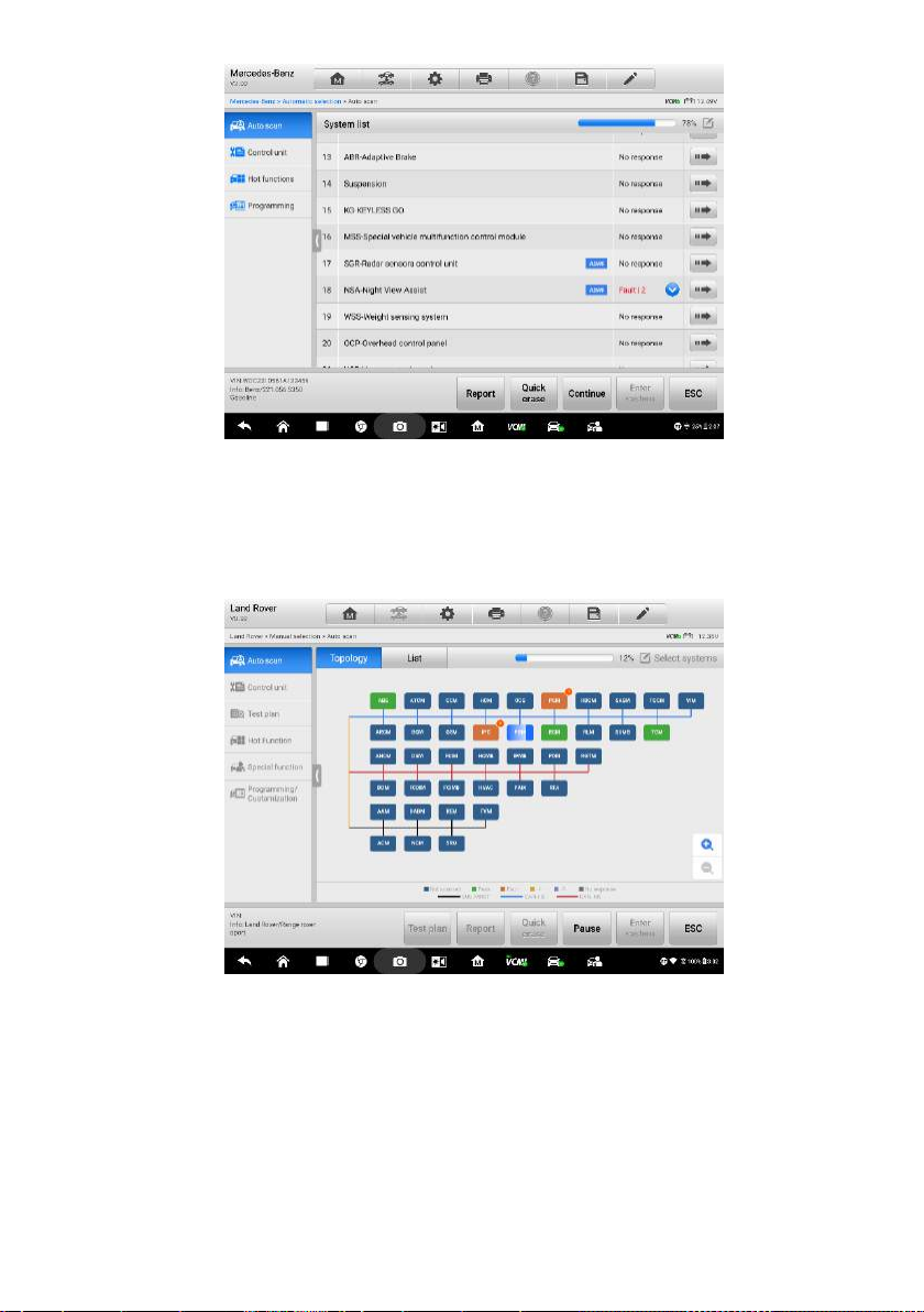
Figure 5-1 Sample System List Screen
For some vehicles, like Volkswagen, Audi, BMW, Ford, Land Rover, Jaguar, Chrysler,
Fiat, Volvo, a topology is added for presenting the relations and differences of vehicle
systems.
Figure 5-2 Sample Topology Display Screen
To review the Auto scan procedures, see Chapter 4 Basic Diagnostic Operation
(Getting Started)
To access the system
1. Tap the List button, a list of modules is scanned or in the process of
scanning.
66
Page 73
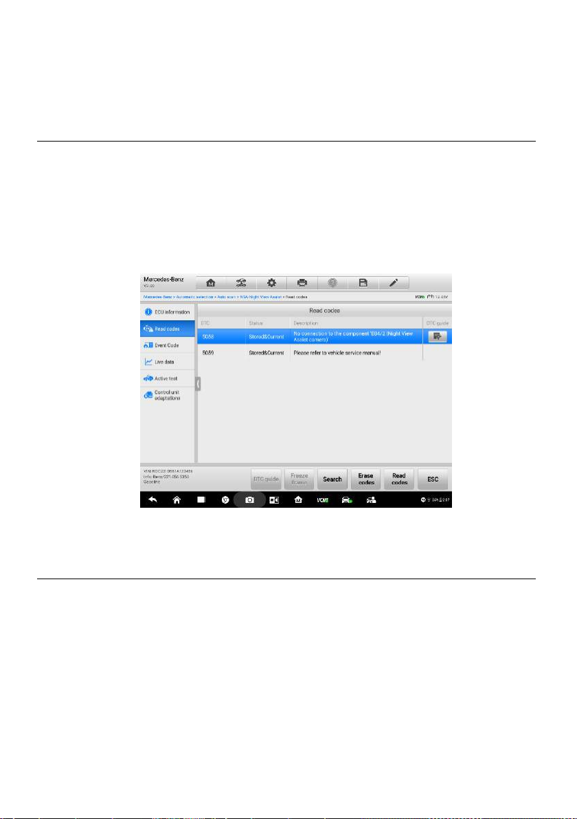
2. Choose one entry from the module list.
3. Tap the grey arrow icon (Figure 5-1 System list) on the right of the entry to
enter a screen with code results dropdown.
5.2 Code Results Dropdown Menu
The first step is to read the DTCs through Read codes. For detailed procedure, see
Read Code in Basic Diagnostic Operation.
After DTCs have been read, the code results dropdown menu is displayed together with
status and description. There are some diagnostic icons in grey color (Figure 5-3 DTC
code dropdown menu) on the right and under the DTC guide. Select one of these
icons and enter the core of Repair Assist - repair case
Figure 5-3 Sample DTC Code Dropdown Menu
5.3 Repair Case Screen Layout
Repair Assist is divided into 6 main sections and sub-sections with multiple diagnostic
procedures and repair cases. Each section contains detailed description and
introduction.
67
Page 74

Figure 5-4 Sample Repair Case Layout
1. Title - displays the year, brand, and model of the vehicle, together with its fault.
2. Technical Service Bulletin - contains code-specific Recalls, TSB, and OEM
campaigns.
3. Frequency of Occurrence - graphically displays the frequency tendency of
different types of faults as mileage increases.
4. Troubleshooting - displays the detailed steps of detecting and clearing DTCs.
5. Real Fixes - sums up fix steps for real repair in a simpler way.
6. Autel tool link - offers links for buying Autel diagnostic tools.
7. Relevant Repair Information - describes repair procedures in detail.
8. Subdivision steps - shows specific operations on components during
maintenance.
9. Relevant Cases - recommends other relevant fault-clearing cases for the same
type of vehicle.
68
Page 75

5.4 Technical Service Bulletin (OEM Information)
The Technical Service Bulletin provides a precise tool for matching the selected fault
code with relevant TSB or OEM. It shortens searching time, simplifies operational
procedures, and directly displays the data as required.
Figure 5-5 Sample TSB Screen
For details, please tap the TSB icon, and you will see a file unfolded with OEM
Information. The following graph is an example of cause analysis of image interference
in night view system with exact TSB information, complaint, causes, remedy and
relevant symptoms for the vehicle.
Figure 5-6 Sample Detailed TSB Screen
5.5 Frequency of Occurrence
The Frequency of Occurrence graph shows the frequencies of different faults as
mileage increases.
69
Page 76

Figure 5-7 Sample Frequency of Occurrence Graph
Graph example: As is shown in the graph below, each fault has its changing frequency
that peaks at a certain mileage. Before the mileage reaches 100k miles, the camera
internal fault occurs more frequently than other fault types, with its highest frequency of
10 coming at 70k miles, while line connection fault between control module of Night
View Assist system (N101) and dynamic CAN high distributor X30/28 occurs as
frequently as 10 at 90k miles. As the mileage approaches 110k miles, the occurrence of
the two faults drops, giving way to Night View Assist system control module fault which,
after reaching 9 at 110k miles, starts to decline at the same point. Another line fault
between camera (B84/2) and control module of Night View Assist (N101), poses not
much threat in the previous 110k miles, but it boasts a maximum occurrence of 8 when
the vehicle travels 130k miles. Similarly, the power supply fault of control module of
Night View Assist (N101) becomes most worrisome at 150k miles.
In conclusion, the graph provides a convenient reference to locating possible faults of
the Night View Assist function in accordance with the driving mileage.
5.6 Troubleshooting
Troubleshooting presents a series of diagnostic and repair steps from confirming fault
symptoms to clearing the faults. Troubleshooting is not only introduced by the way of
words description, but also presented by video explanation for some specific vehicles’
repairing process.
70
Page 77

Figure 5-8 Sample Troubleshooting Description 1 (Words)
Figure 5-9 Sample Troubleshooting Description 2 (Video)
5.7 Real Fixes
Real fixes gives a brief introduction of real repair operations. Follow these steps and
start your repair tests.
71
Page 78

Figure 5-10 Sample Repair Fixes Steps Screen
When a diagnostic tool is required during the repair process, tap the following link of
Autel official website and buy the tools you need. Https://www.auteltech.com/
5.8 Relevant Repair Information
This part is described with OEM test or other operating guidance for specific repair
steps. In order to present clear and professional repair information, multiple forms of
description are used, including relevant circuit or wiring diagrams, tablets, vehicle
structures analysis, and components separation, together with a lot of key notes.
Figure 5-11 Sample Relevant Repair Info Screen 1
72
Page 79

Figure 5-12 Sample Relevant Repair Info Screen 2
5.9 Relevant Cases
This part offers relevant repair cases of different vehicle models with similar faults or
the same vehicle model with different faults. To make the best of the repair cases, tap
the related items recommended, and you will get more knowledge of the same fault.
Figure 5-13 Sample Relevant Repair Info Screen 2
How to move with the procedure?
1. Tap the repair case icon and enter its main page.
2. Scroll through the page and find the information you want.
3. After finishing the browsing, you can tap the arrow icon at the left top and
return to the previous repair case page.
73
Page 80
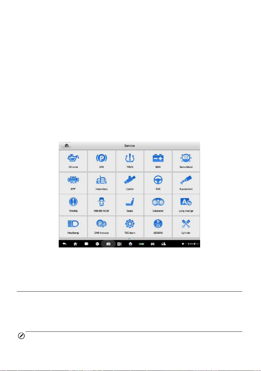
6 Service
The Service section is specially designed to provide quick access to the vehicle
systems for various scheduled service and maintenance tasks. The typical service
operation screen is a series of menu driven executive commands. Follow on-screen
instructions to select appropriate execution options, enter correct values or data, and
perform necessary actions. The application will display detailed instructions to complete
selected service operations.
After entering each special function, the screen will display two application choices:
Diagnosis and Hot Functions. The Diagnosis enables the reading and clearing of
codes which is sometimes necessary after completing certain special functions. Hot
Functions consists of sub functions of the selected special function.
Figure 6-1 Sample Service Menu
Several most commonly used services are described in this chapter.
6.1 Oil Reset Service
Perform reset for the Engine Oil Life system, which calculates an optimal oil life change
interval depending on the vehicle driving conditions and climate. The Oil Life Reminder
must be reset each time the oil is changed, so the system can calculate when the next
oil change is required.
NOTE
1. Always reset the engine oil life to 100% after every oil change.
74
Page 81

2. All required work must be carried out before the service indicators are reset.
Failure to do so may result in incorrect service values and cause DTCs to be stored
by the relevant control module.
3. For some vehicles, the scan tool can reset additional service lights such as
maintenance cycle and service interval. On BMW vehicles for example, service
resets include engine oil, spark plugs, front/rear brakes, coolant, particle filter,
brake fluid, micro filter, vehicle inspection, exhaust emission inspection and vehicle
checks.
6.2 Electric Parking Brake (EPB) Service
This function has a multitude of usages to maintain the electronic braking system safely
and effectively. The applications include deactivating and activating the brake control
system, assisting with brake fluid control, opening and closing brake pads, and setting
brakes after disc or pad replacement.
6.2.1 EPB Safety
It can be dangerous to perform Electric Parking Brake (EPB) system maintenance, so
before you begin the service work, please keep these rules in mind.
Ensure that you are fully familiar with the braking system and its operation before
commencing any work.
The EPB control system may be required to be deactivated before carrying out any
maintenance/diagnostic work on the brake system. This can be done from the tool
menu.
Only perform maintenance work when the vehicle is stationary and on level
ground.
Ensure that the EPB control system is reactivated after the maintenance work has
been completed.
NOTE
Autel accepts no responsibility for any accident or injury arising from the maintenance
of the Electric Parking Brake system.
6.3 Tire Pressure Monitoring System (TPMS) Service
This function allows you to quickly look up the tire sensor IDs from the vehicle’s ECU,
as well as to perform TPMS replacement and reset procedures after tire sensors are
replaced.
75
Page 82

6.4 Battery Management System (BMS) Service
The Battery Management System (BMS) allows the tool to evaluate the battery charge
state, monitor the close-circuit current, register the battery replacement, activate the
rest state of the vehicle, and charge the battery via the diagnostic socket.
NOTE
1. This function is not supported by all vehicles.
2. The sub functions and actual test screens of the BMS may vary by vehicle, please
follow the on-screen instructions to make correct option selection.
The vehicle may use either a sealed lead-acid battery or an AGM (Absorbed Glass Mat)
battery. Lead acid battery contains liquid sulphuric acid and can spill when overturned.
AGM battery (known as VRLA battery, valve regulated lead acid) also contains
sulphuric acid, but the acid is contained in glass mats between terminal plates.
It is recommended that the replacement aftermarket battery has the same
specifications, such as capacity and type, as the exiting battery. If the original battery is
replaced with a different type of battery (e.g. a lead-acid battery is replaced with an
AGM battery) or a battery with a different capacity (mAh), the vehicle may require
reprogramming of the new battery type, in addition to, performing the battery reset.
Consult the vehicle manual for additional vehicle-specific information.
6.5 Diesel Particle Filter (DPF) Service
The Diesel Particle Filter (DPF) function manages DPF regeneration, DPF component
replacement teach-in and DPF teach-in after replacing the engine control unit.
The ECM monitors driving style and selects a suitable time to employ regeneration.
Cars driven a lot at idling speed and low load will attempt to regenerate earlier than cars
driven more with higher load and speed. In order for regeneration to take place, a
prolonged high exhaust temperature must be obtained.
In the event of the car being driven in such a way that regeneration is not possible, i.e.,
frequent short journeys, a diagnostic trouble code will eventually be registered in
addition to the DPF light and “Check Engine” indicators displaying. A service
regeneration can be requested in the workshop using the diagnostic tool.
Before performing a forced DPF regeneration using the tool, check the following items:
The fuel light is not on.
No DPF-relevant faults are stored in system.
The vehicle has the specified engine oil.
The oil for diesel is not contaminated.
76
Page 83

IMPORTANT
Before diagnosing a problem vehicle and attempting to perform an emergency
regeneration, it is important to obtain a full diagnostic log and read out relevant
measured value blocks.
NOTE
1. The DPF will not regenerate if the engine management light is on, or there is a
faulty EGR valve.
2. The ECU must be re-adapted when replacing the DPF and when topping up the
fuel additive Eolys.
3. If the vehicle needs to be driven in order to perform a DPF service, a second
person is needed for the function. One person should drive the vehicle while the
other person observes the screen on the Tool. Do not attempt to drive and observe
the scan tool at the same time. This is dangerous and puts your life and the lives of
other motors and pedestrians at risk.
6.6 Immobilizer (IMMO) Service
An immobilizer is an anti-theft mechanism that prevents an automobile’s engine from
starting unless the correct ignition key or other device is present. This device prevents
thieves from starting the car by a method known as hot wiring. Most new vehicles have
an immobilizer as standard equipment. An important advantage of this system is that it
doesn’t require the car owner to activate it; it operates automatically. An immobilizer is
considered as providing much more effective anti-theft protection than an audible alarm
alone; many auto insurance companies offer lower rates for vehicles that are equipped
with an immobilizer.
As an anti-theft device, an immobilizer disables one of the systems needed to start a
car's engine, usually the fuel supply or the ignition. This is accomplished by radio
frequency identification between a transponder in the ignition key and a device called a
radio frequency reader in the steering column. When the key is placed in the ignition,
the transponder sends a signal with a unique identification code to the reader, which
relays it to a receiver in the vehicle's computer control module. If the code is correct, the
computer allows the fuel supply and ignition systems to operate and start the car. If the
code is incorrect or absent, the computer disables the system, and the car will be
unable to start until the correct key is placed in the ignition.
The IMMO service can disable a lost vehicle key and program the replacement key fob.
One or more replacement key fobs can be programmed.
77
Page 84

6.7 Steering Angle Sensor (SAS) Service
Steering Angle Sensor Calibration permanently stores the current steering wheel
position as the straight-ahead position in the steering angle sensor EEPROM.
Therefore, the front wheels and the steering wheel must be set exactly to the
straight-ahead position before calibration. In addition, the vehicle identification number
(VIN) is also read from the instrument cluster and stored permanently in the steering
angle sensor EEPROM. On successful completion of calibration, the steering angle
sensor fault memory is automatically cleared.
Calibration must always be carried out after the following operations:
Steering wheel replacement
Steering angle sensor replacement
Any maintenance that involves opening the connector hub from the steering angle
sensor to the column
Any maintenance or repair work on the steering linkage, steering gear or other
related mechanism
Wheel alignment or wheel track adjustment
Accident repairs where damage to the steering angle sensor or assembly, or any
part of the steering system may have occurred
NOTE
1. Autel accepts no responsibility for any accident or injury arising from servicing the
SAS system. When interpreting DTCs retrieved from the vehicle, always follow the
manufacturer’s recommendation for repair.
2. All software screens shown in this manual are examples, actual test screens may
vary by test vehicle. Pay attention to the menu titles and onscreen instructions to
make correct option selections.
3. Before starting procedure, make sure vehicle has an ESC button. Look for button
on dash.
78
Page 85
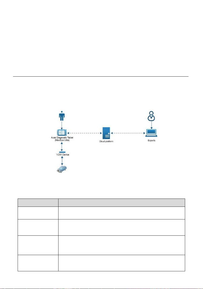
Name
Description
VCMI device
Build a link between the vehicle and the Autel diagnostic tablet.
MaxiSys Ultra
Tap the Remote Programming module on its screen for
uploading diagnostic data and other questions.
Cloud platform
Transmit diagnostic data from the vehicle side to the experts,
making it possible for the experts doing OEM remote
programming for vehicle diagnosis.
Experts
Provide technical support for diagnostic troubles based on
OEM software.
7 Remote Programming
Remote Programming Operation is a support function based on data transmission
through Cloud platform, providing remote programming for solving tricky diagnostic
troubles.
7.1 General Introduction
Remote programming operation uses the Cloud platform to build an invisible bridge that
connects the client diagnostic tablet with experts that have OEM software information.
The following figure gives you a more intuitive presentation of the principles of the
Remote Programming function.
Figure 7-1 Principles of Remote Programming
Table 7-1 Description of Remote Programming principle
79
Page 86
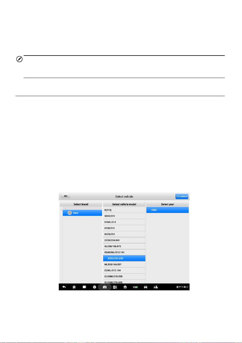
The Remote Programming is a newly developed module which supplements the
MaxiSys Ultra in vehicle diagnosis. It overcomes the distance problem and expands the
functions of the MaxiSys Ultra diagnostic tablet. Apart from that, Remote Programming
provides instant support for dealing with new faults in diagnosing the latest vehicle
models.
NOTE
Except for the above professional functions, Remote Programming cannot be ignored
also because the expert support is free of charge.
7.2 Getting Started
Before getting started, a proper connection between the vehicle and VCMI is required.
When faults have been detected, there is no way to solve it because of OEM restriction.
It is time for you to log in to the Remote Programming module on the MaxiSys Ultra
tablet. Remote Programming has a quite easy access channel, just follow the steps
below:
To open the Remote Programming application:
1. Tap the Remote Programming icon to enter the Homepage. (VIN is
auto-matched during the procedure.)
2. Select relevant vehicle information (brand, model, and year).
3. Tap the Finish icon in the upper right corner of the screen.
Figure 7-2 Sample Vehicle Selection Page
80
Page 87
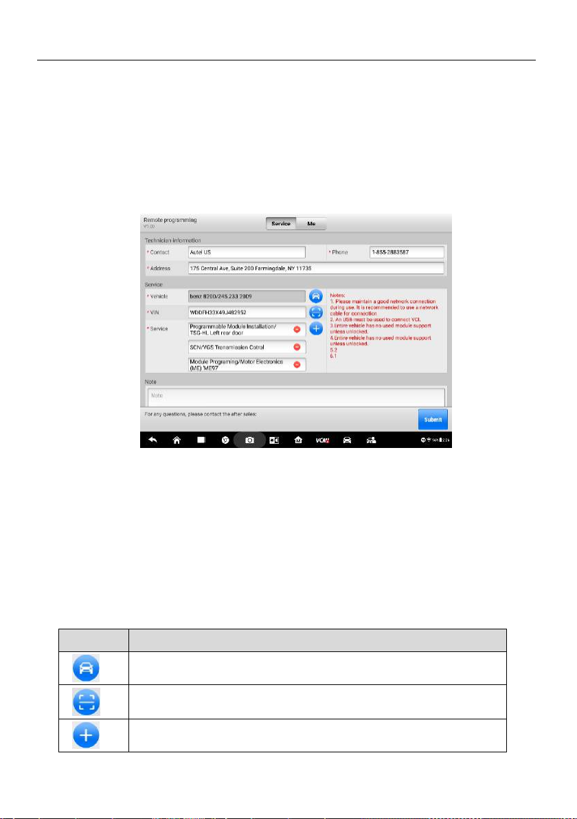
Icon
Description
For selecting vehicle brands and models.
For scanning the VIN code of the vehicle.
For adding exact Service types.
7.3 Operation
The Remote Programming Operation process consists of 3 main steps, namely, order
submission, order confirmation, and the most critical, remote programming. Besides,
historical order serves as a reminder of your previous data information.
7.3.1 Submit Order
When you see the Service and Orders tabs at the top, you have entered the Submit
Order page.
Figure 7-3 Sample Submit Order Page
Input the Technician information and Service information according to the notes
prompted. Please make sure that your phone number is correct and real existed, for our
experts will contact you through phone calls for further communication on vehicle
problems.
In the Service information section, there are 3 blue buttons to the right of the boxes.
These buttons are available for quick filling. For detailed operation, see the table below.
Table 7-2 Functions of Buttons
81
Page 88
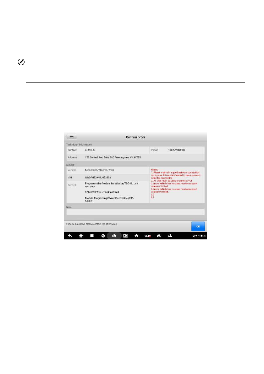
The Note contents in red color on the middle right side are tips for doing the remote
programming connection. While the Notes at the bottom are designed for writing
vehicle troubles for experts’ reference.
After all information have been input, tap the Submit button to proceed.
NOTE
Each box that starts with a red asterisk must be filled. The information input must be
valid and genuine.
7.3.2 Confirm Order
As the order has been submitted, you are directed to the Confirm Order page. Make a
quick check about the contents that you have input before and then tap the blue button
OK to continue.
Figure 7-4 Sample Confirm Order Page 1
If you do not want to continue with this order, or if you find any errors in your order, you
can tap the Cancel button in the lower right corner to terminate the procedure.
82
Page 89
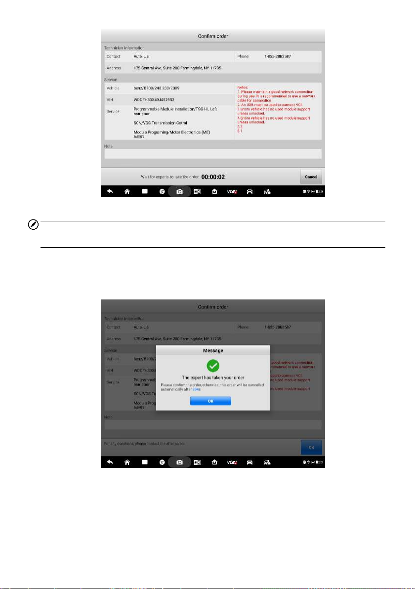
Figure 7-5 Sample Confirm Order Page 2
NOTE
This Cancel button can be pressed only before the expert takes your order.
After the expert takes your order, a message will appear asking for your confirmation.
You need to confirm this order within 5 minutes. Otherwise, this order will be canceled
automatically
Figure 7-6 Sample Confirm Order Page 3
7.3.3 Remote Programming
Once the expert has received your order, the Remote Programming page appears. At
this point, the expert starts to perform remote programming. If you want to see how the
83
Page 90

expert programs, tap the Remote desktop in the upper right corner. Once the expert
accepts your request, you will have access to the expert’s computer desktop. But it is
also possible that the expert rejects your request. To accept or not to accept, it is totally
up to the expert.
7.3.3.1 Request Accepted
When the expert accepts your request, you will see a shared desktop showing a series
of programming operations as in the figure below.
Figure 7-7 Sample Remote Programming Page 1
Figure 7-8 Sample Remote Programming Page 2
84
Page 91

Figure 7-9 Sample Remote Programming Page 3
Figure 7-10 Sample Remote Programming Page 4
These operations are based on the OEM software which authorizes the expert to do
programming and help you diagnose the vehicle.
7.3.3.2 Request Rejected
If the expert rejects your request, you will receive a rejection message.
85
Page 92

Figure 7-11 Sample Request Rejected Page
7.3.3.3 Programming Finished
When Remote Programming is finished, a message will be returned saying
Programming is over, please wait for expert to upload the report….
After that, you will be redirected to the Program Report page that shows the status,
Success or Failure, of each programming procedure.
Figure 7-12 Sample Program Report Page
NOTE
A PDF report file is attached to each record. Tap it to see the detailed output
information.
86
Page 93

7.3.4 Historical Orders
Historical orders are orders completed or not completed out of subjective or objective
reasons, such as proactive cancellation, unexpected networking disconnection, or
unexpected power-off.
Tap the Orders button, and you will see the historical orders.
Figure 7-13 Sample Historical Orders Page
Both Completed and Incomplete orders are recorded in this part. For Completed orders,
the programming report is available if you tap the blue button Report. For Incomplete
orders, you can resubmit them.
To resubmit the incomplete orders.
1. Tap the Submit button, and the Incomplete orders page appears.
2. Check and confirm the information on the Incomplete orders page.
3. Tap OK to continue.
4. After the waiting page appears, wait for the expert to take orders.
5. A Message saying Expert has received the order appears Tap OK after
you confirm the message.
NOTE
You need to confirm the order before it is canceled automatically after 5 minutes.
87
Page 94

8 MaxiFix
MaxiFix is an online community, based on the ever-expanding cloud database that
provides abundant information and resources to help find efficient solutions for all kinds
of vehicle troubles. It serves as a forum allowing the users to network with other
MaxiSys users and Autel Technicians, including posting questions, answering
questions, sharing tips and searching for repair cases with proven documented fixes.
Apart from the truth that the MaxiFix provides the abundant troubleshooting information
available, the database keeps growing with daily feed of reported solution cases and
advisory reports from MaxiSys users worldwide.
Information in the MaxiFix database is organized into a series of diagnostic tips that are
designed to help you locate the cause of particular problems of the test vehicle and
quickly find solutions to them.
8.1 Getting Started
The MaxiFix application is accessible by tapping the MaxiFix icon in blue. This
application supports automatic login because it can recognize the serial number and
password of the Autel MaxiSys Ultra tablet intelligently.
8.2 Navigation
When entering the MaxiFix, you will see a full screen layout as shown in Figure 8-1
below.
Figure 8-1 Sample MaxiFix Home Page
88
Page 95

The MaxiFix screen layout contains 3 main areas:
1. The Navigation Bar – the top Navigation Bar allows you to switch between
different sections of MaxiFix. Besides, a bell-shaped icon and a bust icon are
located in the upper right corner of the screen, which lead to messages and
personal information respectively.
2. The Function Menu – on the upper left side under the Navigation Bar, the
Function Menu displays the submenus of each main menu.
3. The Main Screen – occupying the rest of the screen, the Main Screen displays
vehicle-related content including problems and corresponding solutions, interactive
activities, tips and information posted by Autel MaxiSys Ultra users.
Message Icon & Personal Center Icon
Message Icon
The bell-shaped icon in the upper right corner reminds you of messages about your
activities on MaxiFix.
Tap the icon to enter the My Messages page where you can see a list of messages
read or unread. If a piece of message is not read, the entry is in dark black; otherwise,
the entry turns to gray.
These unread messages can be set as read once you tap the All set as read button. If
there are too many messages, you can tap the Clear button to clear the message
history.
Personal Center Icon
Next to the message icon, the bust icon leads to Personal Center.
Figure 8-2 Sample Personal Center Page
89
Page 96

Personal Center consists of six tab pages, with Personal Information, Question,
Answer, Share, Favorite, and Daily Task being their respective tab tile. Each tab
page shows a different aspect of the user’s activities on MaxiFix.
Personal Information –contains the account registration, Support and Switch account
functions. In the upper right corner opposite to the account name, there is a blue button,
where you can apply for technician authentication
To apply for the authentication
1. Tap the Authentication button and enter the Technician Accreditation page.
2. Fill in the information required in each empty box.
3. Do not forget to upload HD pictures of certificate.
4. Tap Submit to send your application.
5. After all has been done, please wait for verification. As long as your
information meets the required standards, you will get a successful
authentication soon.
Back to the main screen of Personal Information, Support offers a feedback channel
for sharing user experience on MaxiFix and viewing FAQs. MaxiFix allows other
accounts to log in. You can tap Switch Account to switch to another account.
Question – records the posted questions in the MaxiFix community.
Answer – records your answers to others’ questions.
Share –presents analysis of troubleshooting vehicles and tips for diagnosis shared by
yourself.
Favorite – collects questions, shares, and repair cases you saved before.
Daily task – provides various tasks with reward coins. You can do daily tasks to earn
coins and community experience values. The daily tasks include sharing tips, posting
questions, and answering pending questions. The detailed operation is explained in
Community.
8.3 Operations
The top navigation bar consists of Home, Real Fixes, Academy and Integral Mall, the
functions of which are shown below:
Community – shows questions and answers about vehicle problems and fault code
solutions. Moreover, this section offers a good chance to join the MaxiFix community.
Real Fixes – presents real cases collected from actual shop repair orders and
described in an easy-to-understand and professional manner.
90
Page 97
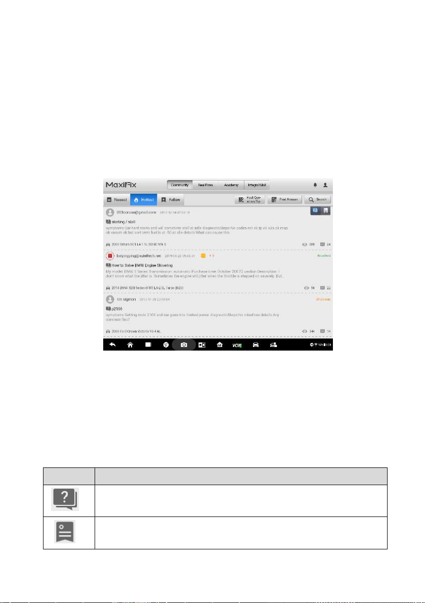
Icon
Description
Signifying that what follows is a question.
Signifying that what follows is a service tip.
Academy – offers an online learning and help platform for vehicle diagnosis
technicians, with videos concerning various specific topics and query tools for
searching vehicle information.
Integral Mall – displays a series of Autel diagnostic products, including diagnostic
tablets, endoscope, and oscilloscope, and other diagnostic components, etc. These
products can be exchanged with reward coins that you won from daily tasks and other
tasks. For detailed exchange steps, see Integral Mall.
8.3.1 Community
The Community menu showcases the MaxiFix community with three tab pages.
Figure 8-3 Sample Community Page
Three tab pages:
Newest – contains questions and tips about exact vehicle faults posted by the
MaxiSys Ultra users in chronological order. The icon with a question mark leads to
a question posted by MaxiSys Ultra users; while the bookmark icon represents
that the following is a service tip shared by MaxiSys Ultra users.
Table 8-1: Table of Small Icons in MaxiFix
91
Page 98

Icon
Description
Signifying the number of views.
Signifying the number of adoptions for the service tip.
Signifying the number of answers to the question.
Signifying the number of reward coins.
Each question is accompanied with two icons indicating the number of views and
answers respectively. Similarly, each repair tip is accompanied with two icons
indicating the number of views and adoptions.
Some of the questions are attached with a coin icon, indicating the number of reward
coins provided for the best answer. The questioner can raise the number of reward
coins to stimulate better solutions.
To the right of the questions, the orange phrase Underway indicates that the question
has been answered by experts or technicians but not confirmed by the questioner;
while a green word Resolved indicating that the questioner has been confirmed with
the best answer.
Hottest – displays hot questions with the most replies from experts or other
professional MaxiSys Ultra users, along with the most views.
For viewing convenience, entries under the Hottest menu are divided to be shown in
two modes. Tap the question mark icon, and the screen only displays questions posted
by users. Tap the bookmark icon, and the screen only shows service tips shared by
users. (For icon meanings, see Table 8-1: Table of Small Icons in MaxiFix)
Follow – displays the questions and tips that you are following. The Select
Vehicle button to the left allows you to make a quick selection of specific vehicles.
To select a vehicle
1. Tap the blue Select Vehicle button to the left.
2. Select Brand of the vehicle from the list.
3. Select Model of the vehicle from the list.
After finishing the vehicle selection procedure, the identified vehicle is shown in the
Follow tab page, with related user-posted questions and tips, matched and displayed
together with user IDs. Tap one of the matched entries to see the details.
92
Page 99

Three Function Buttons:
The three function buttons in the upper right corner are designed to enable online
communication between MaxiSys Ultra users and Autel experts.
Post Question/Tip – This button provides a channel to ask questions about
vehicle faults and share good solutions to diagnostic troubles.
To post a question/tip
1. Tap the Post Question/Tip button to enter the Post Question and
Sharing Tip page.
2. Tap the Select Vehicle button, select Year, Brand, Model, and Engine
from the list.
3. Fill in the Subject in short phrases or a short question with keyword.
4. Fill in Credit Reward as a reward for the best answer.
5. Write your question or expression about vehicle faults in the Content box.
(Three different posting ways are available, including picture, video and
voice.)
6. After all have done above, tap Submit in the upper right corner. And your
question will be uploaded soon on the list of the Newest.
NOTE
The steps of posting a sharing tip are similar to posting a question, except that step 4 is
not included in Sharing Tip.
Once a question has been posted, the entry is presented with the Question icon.
While a tip has been posted, the entry is presented with the Service Tip icon.
Post Answer – This button is for answering questions posted by other MaxiSys
Ultra users.
To post an answer
1. Tap the Post Answer button to enter the Pending Questions page.
2. Select To be answered, and you will see a list of unanswered questions.
Select Underway, and you will see a list of questions with some but no
best answers.
3. Tap one question entry, and enter a page with a blue Post Answer button
to the right.
4. Tap the Post Answer button to enter the Reply page.
93
Page 100
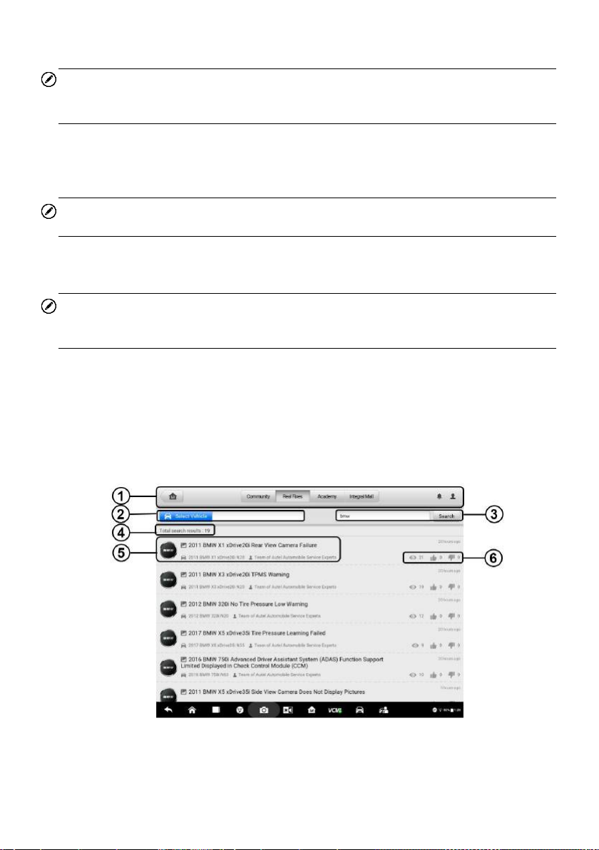
5. Post your analysis and insights in the Content box.
NOTE
Three different posting ways are available, including with a maximum of 5 pictures, a
video within 15 seconds or a voice within 3 minutes.
As long as your answer is adopted by the questioner, the system will automatically
award you reward coins. If your answer is confirmed as the Best Answer, you will
receive reward coins from both the system and the questioner.
NOTE
You can complement your answer via the Continue Answer button.
Search – This button enables you to search for answers and solutions to
questions and troubles, as convenient and efficient as to search in Google.
NOTE
The most-searched keywords will be memorized in Hot Search, and the Search
History records the keywords you input.
8.3.2 Real Fixes
In Real Fixes, a list of repair cases and troubleshooting tips are collected by way of
content instructions and graph analysis. Additionally, some repair cases are attached
with videos showing the whole process of troubleshooting. This kind of visual
presentation is much more intuitive and instructive, compared with words introduction.
Figure 8-4 Sample Real Fixes Page 1
There are six function parts in Real Fixes, as explained below:
94
 Loading...