

Page 1

Trademarks
Autel®, MaxiSysTM, MaxiDAS®, MaxiScan®, MaxiTPMS®, MaxiVideoTM, MaxiRecorderTM,
and MaxiCheck
in China, the United States and other countries. All other marks are trademarks or
registered trademarks of their r es pective holders.
TM
are trademarks of Autel Intelligent Technology Corp., Ltd., registered
Copyright Information
No part of this manual may be reproduc ed, stored in a ret rieval system or transmitted,
in any form or by any means, electronic, mechanical, photocopying, recording, or
otherwise, without the prior written permissi on of Autel.
Disclaimer of Warranties and Limitation of Liabilities
All information, specifications and i llustrations in this manual are based on the latest
information available at the time of printing. Autel reserves the right to make changes at
any time without notice. While information of this manual has been carefully chec ked
for accuracy, no guarantee is given to the completeness and correctness of the
contents, including but not limited to the product specifications, functions, and
illustrations.
Autel will not be liable for an y direct damages or for any special, inc idental, or indir ect
damages or for any economic consequential damages (including lost profits).
IMPORTANT: Before operating or maintaining this unit, please read this manual
carefully, paying extra attention to the safety warnings and precaut ions.
For Services and Support:
http://pro.autel.com
www.autel.com
1-855-288-3587/1-855-AUTELUS (North America)
0086-755-86147779 (China)
Support@autel.com
For technical assistance in all ot her markets, please contact your local s elling agent.
i
Page 2

Safety Information
For your own safety and the safety of others, and to pr event damage to the device and
vehicles upon which it is used, it is important that the safety instructions herein
presented throughout this manual be read a nd understood b y all persons oper ating, or
coming into contact with, the device.
There are various procedures , techniques, tools, and parts for servicing vehi cles, as
well as in the skill of the person do ing the work. Because of the vast number of test
applications and variations in the products that can be test ed with this equipment, we
cannot possibly anticipate or provide advice or safety messages to cover every
circumstance. It is the automotive technician’s responsibility to be knowledgeable of the
system being tested. It is crucial t o use pro per servi ce methods and test procedur es. It
is essential to perform tests in an appropr iate and acceptable manner that does not
endanger your safety, the safety of others in the work area, t he device being used, or
the vehicle being tested.
Before using the device, always refer to and follow the safety messages and applicable
test procedures provided by the manufactur er of the vehicle or equipment being tested.
Use the device only as described in this manual. Read, understand, and follow all
safety messages and instructions in this manual.
Safety Messages
Safety messages are provided t o help pr eve nt perso nal i njur y and equi pment d amage.
All safety messages are introduced by a signal word indicating the hazard l evel.
DANGER: Indi c ates an imminently hazardous situation which, if not av oide d, will
result in death or serious injury to the operator or to bystanders.
WARNING: Indicates a potentially hazardous situation which, if not avoided,
could result in death or serious injury to the operator or to bystanders.
Safety Instructions
The safety messages herein cover situations Autel is aware of. Autel cannot know,
evaluate or advise you as to all of the possible h azards. You must be certain that any
condition or service procedure encountered do not jeopardize your person al safety.
DANGER: When an engine is operating, keep the service area WELL
VENTILATED or attach a building exhaust removal system to the engine exhaust
system. Engines produce carbon monoxide, an odorless, poisonous gas that
causes slower reaction time and can lead to ser ious personal injury or loss of
life.
ii
Page 3

Safety Information Important Safety Instructions
Do Not Turn the Volume Up Too Loud When Using Headphones
Listening at high volumes that over -stimulate the ear for long periods of time
may result in loss of hearing.
SAFETY WARNINGS:
Always perform automotive testing in a safe environment.
Wear safety eye protection that meets ANSI standards.
Keep clothing, hair, hands, tools, test equipment, etc. away from all
moving or hot engine parts.
Operate the vehicle in a well ventilat ed work area, for exhaust gases ar e
poisonous.
Put the transmission in PARK (for automatic transmission) or NEUTRAL
(for manual transmission) and make sure the parking brake is engaged.
Put blocks in front of the drive wheels and never leave the vehicle
unattended while testing.
Use extreme caution when working around the ignition coil, distributor cap,
ignition wires and spark plugs. These components create hazardous
voltages when the engine is running.
Keep a fire extinguisher suitable for gasoline, chemical, and electrical fires
nearby.
Do not connect or disconnect any test equipment while the ignition is on or
the engine is running.
Keep the test equipment dry, clean, free from oil, water or grease. Use a
mild detergent on a clean cloth to c lean the outside of the equipment as
necessary.
Do not drive the vehicle and operate the tes t equ ipme nt at the sam e ti me .
Any distraction may cause an accid ent.
Refer to the service manual for the vehicle being service d and adhere to
all diagnostic procedures and precautions. Failure to do so may result in
personal injury or damage to the test equipment.
To avoid damaging the test equipment or generating false data, make
sure the vehicle battery is fully ch arged and the con nection to the v ehicle
DLC is clean and secure.
Do not place the test equipm ent on the distributor of the vehicl e. Strong
electro-magnetic interference c an damage the equipment.
iii
Page 4

Contents
SAFETY INFORMATION .......................................................................................... II
CHAPTER 1 USING THIS MANUAL ..................................................................... 1
1.1 CONVENTIONS .................................................................................................... 1
1.1.1 Bold Text .................................................................................................. 1
1.1.2 Terminology ............................................................................................ 1
1.1.3 Notes and Important Messages .............................................................. 1
1.1.4 Hyperlinks ................................................................................................ 1
1.1.5 Procedures ............................................................................................... 2
CHAPTER 2 GENERAL INTRODUCTION .............................................................. 3
2.1 MAXISYS DISP LAY TABLET ..................................................................................... 3
2.1.1 Functional Description ............................................................................. 3
2.1.2 Power Sources ......................................................................................... 5
2.1.3 Technical Specifications ........................................................................... 5
2.2 VCI – J2534 ECU PROGRAMMING DEVICE ............................................................. 7
2.2.1 Functional Description ............................................................................. 7
2.2.2 Power Sources ......................................................................................... 8
2.2.3 Technical Specifications ........................................................................... 9
2.3 DOCKING STATI ON ............................................................................................... 9
2.3.1 Functional Description ............................................................................. 9
2.3.2 Technical Specifications ......................................................................... 10
2.4 ACCESSORY KIT ................................................................................................. 10
2.4.1 Main Cable ............................................................................................ 10
2.4.2 OBD I Adapters ...................................................................................... 11
2.4.3 Other Accessories .................................................................................. 11
CHAPTER 3 GETTING STARTED........................................................................ 13
3.1 POWERING UP .................................................................................................. 13
3.1.1 Application Buttons ............................................................................... 14
3.1.2 Locator and Navigation Buttons ............................................................ 15
3.1.3 System Status Icons ............................................................................... 16
3.2 POWERING DOWN ............................................................................................ 16
3.2.1 Reboot System ....................................................................................... 17
3.3 INSTALLING COMPUTER SOFTWARE ....................................................................... 17
3.3.1 Printing Operation ................................................................................. 17
CHAPTER 4 DIAGNOSTICS OPERATIONS .......................................................... 19
Page 5

4.1 ESTABLISHING VEHICLE COMMUNICATION .............................................................. 19
4.1.1 Vehicle Connection ................................................................................ 19
4.1.2 VCI Connection ...................................................................................... 21
4.1.3 No Communication Message ................................................................ 24
4.2 GETTING START ED ............................................................................................. 25
4.2.1 Vehicle Menu Layout ............................................................................. 25
4.3 VEHICLE IDENTIFICATION ..................................................................................... 27
4.3.1 Auto VIN Scan ........................................................................................ 27
4.3.2 Manual VIN Input .................................................................................. 28
4.3.3 Manual Vehicle Selection ...................................................................... 29
4.3.4 Alternative Vehicle Identification .......................................................... 32
4.4 NAVIGATION ..................................................................................................... 32
4.4.1 Diagnostics Screen Layout ..................................................................... 32
4.4.2 Screen Messages ................................................................................... 35
4.4.3 Making Selections ................................................................................. 36
4.5 MAIN MENU .................................................................................................... 36
4.6 DIAGNOSIS ....................................................................................................... 37
4.6.1 ECU Information .................................................................................... 41
4.6.2 Read Codes ............................................................................................ 42
4.6.3 Erase Codes ........................................................................................... 43
4.6.4 Live Data ................................................................................................ 43
4.6.5 Active Test ............................................................................................. 50
4.6.6 Special Functions ................................................................................... 51
4.7 SERVICE ........................................................................................................... 52
4.7.1 Function Descriptions ............................................................................ 52
4.8 PROGRAMMING AND CODING .............................................................................. 53
4.9 GENERIC OBD II OPERATIONS ............................................................................. 57
4.9.1 General Procedure ................................................................................. 57
4.9.2 Function Descriptions ............................................................................ 59
4.10 EXITING DIAGNOSTICS .................................................................................... 62
CHAPTER 5 DATA MANAGER OPERATIONS ...................................................... 63
5.1 OPERATIONS..................................................................................................... 63
5.1.1 Image Files ............................................................................................ 63
5.1.2 PDF Files ................................................................................................ 65
5.1.3 Review Data .......................................................................................... 66
5.1.4 Apps Manager ....................................................................................... 66
5.1.5 Data Logging ......................................................................................... 67
CHAPTER 6 MAXIFIX OPERATIONS .................................................................. 68
6.1 NAVIGATION ..................................................................................................... 68
Page 6

6.1.1 Terminology ........................................................................................... 70
6.2 OPERATIONS..................................................................................................... 71
6.2.1 Home ..................................................................................................... 71
6.2.2 My MaxiFix ............................................................................................ 73
6.2.3 Search Fix .............................................................................................. 75
6.2.4 All Questions.......................................................................................... 76
6.2.5 My Messages......................................................................................... 76
6.2.6 Support .................................................................................................. 77
CHAPTER 7 SETTINGS OPERATIONS ................................................................ 78
7.1 OPERATIONS..................................................................................................... 78
7.1.1 Unit ........................................................................................................ 78
7.1.2 Language ............................................................................................... 79
7.1.3 Printing Setting ...................................................................................... 79
7.1.4 Wired Network ...................................................................................... 79
7.1.5 Notification Center ................................................................................ 80
7.1.6 Multitask ............................................................................................... 81
7.1.7 About ..................................................................................................... 81
7.1.8 System Settings ..................................................................................... 82
CHAPTER 8 SHOP MANAGER OPERATIONS ..................................................... 83
8.1 VEHICLE HISTORY .............................................................................................. 84
8.1.1 Historical Test Record ............................................................................ 85
8.2 WORKSHOP INFORMATION .................................................................................. 86
8.3 CUSTOMER MANAGER ....................................................................................... 87
8.3.1 History Notes ......................................................................................... 89
CHAPTER 9 UPDATE OPERATIONS ................................................................... 91
CHAPTER 10 VCI MANAGER OPERATIONS ......................................................... 93
10.1 BLUETOOTH PAIRING ...................................................................................... 94
10.2 WIRED NETWORK CONNECTION ....................................................................... 95
10.3 UPD ATE ....................................................................................................... 96
CHAPTER 11 REMOTE DESK OPERATIONS ......................................................... 97
11.1 OPERATIONS ................................................................................................. 97
CHAPTER 12 SUPPORT OPERATIONS ................................................................ 99
12.1 PRODUCT REGISTRATION ................................................................................. 99
12.2 SUPPORT SCREEN LAYOUT ............................................................................. 100
12.3 MY ACCOUNT ............................................................................................. 101
Page 7

12.4 USER COMPLAINT ........................................................................................ 101
12.5 DATA LOGGING ............................................................................................ 104
12.6 COMMUNITIES ............................................................................................ 105
12.7 TRAINING CHANNELS .................................................................................... 107
12.8 FAQ DATABASE ........................................................................................... 108
CHAPTER 13 TRAINING OPERATIONS ............................................................. 109
CHAPTER 14 QUICK LINK OPERATIONS ........................................................... 111
CHAPTER 15 DIGITAL INSPECTION OPERATIONS ............................................. 112
15.1 ADDITIONAL ACCESSORIES ............................................................................. 113
15.2 TECHNICAL SPECIFICATIONS............................................................................ 116
15.3 OPERATIONS ............................................................................................... 116
CHAPTER 16 MAINTENANCE AND SERVICE ..................................................... 119
16.1 MAINTENANCE INSTRUCTIONS........................................................................ 119
16.2 TROUBLESHOOTING CHECKLIST ....................................................................... 120
16.3 ABOUT BATTERY USAGE ................................................................................ 120
16.4 SERVICE PROCEDURES ................................................................................... 121
CHAPTER 17 COMPLIANCE INFORMATION ..................................................... 123
CHAPTER 18 WARRANTY ............................................................................... 124
Page 8

Chapter 1 Using This Manual
This manual contains device us age instructions.
Some illustrations shown in this man ual may contain mod ules and optional equi pment
that are not i ncluded on your system. Contac t your sales repres entative for ava ilabilit y
of other modules and optional tools or accessories.
1.1 Conventions
The following conventions are used.
1.1.1 Bold Text
Bold emphasis is used to highlight selectable items such as buttons and menu
options.
Example:
Tap OK.
1.1.2 Terminology
The term “select” means highlighting a button or menu item and t apping it to
confirm the selection.
1.1.3 Notes and Important Messages
The following messages are used.
Notes
A NOTE provides helpful information such as additional explanations, tips,
and comments.
Important
IMPORTANT indicates a situation which, if not av oided, may result in damage
to the test equipment or vehicle.
1.1.4 Hyperlinks
Hyperlinks, or links, that take you to other r elated articles, procedures, and
illustrations are available in electronic document s. Blue colored text indic ates
a selectable hyperlink.
1
Page 9

Using This Manual Conventions
1.1.5 Procedures
An arrow icon indicates a procedure.
Example:
To use the camera:
1 Tap the Camera button. The camera screen opens.
2 Focus the image to be captured in t he view finder.
3 Tap the blue circle. The view finder now shows the captured picture
and auto-saves the taken photo.
2
Page 10
Chapter 2 General Introduction
The MaxiSysTM Elite Diagno stic Platform is the next generation of smart solution for
specialized automotive diagnosis. Featuring the NVIDIA’s Tegra
1.90GHz processor, a 9.7” Retina display with a super sensitive capacitive screen
supporting air gesture control, combined with an optimized array of powerful
applications, and the best possible coverage of OE-level diagnostics, the MaxiSys Elite
performs every job from comprehensive vehicle diagnostics & analysis to advanced
ECU programming quickly and efficiently.
There are 3 main components to the MaxiSys Elite system:
MaxiSys Display Tablet – the central processor and monitor for the system
Vehicle Communication Interface (VCI) – the J2534 ECU Programming Device
for accessing vehicle data with programming capabilities
Docking Station – provides optimum visibility and convenient charging
This manual describes the construct ion and operation of these devices and h ow they
work together to deliver diagnostic solutions.
®
4-PLUS-1 quad-core
2.1 MaxiSys Display Tablet
2.1.1 Functional Description
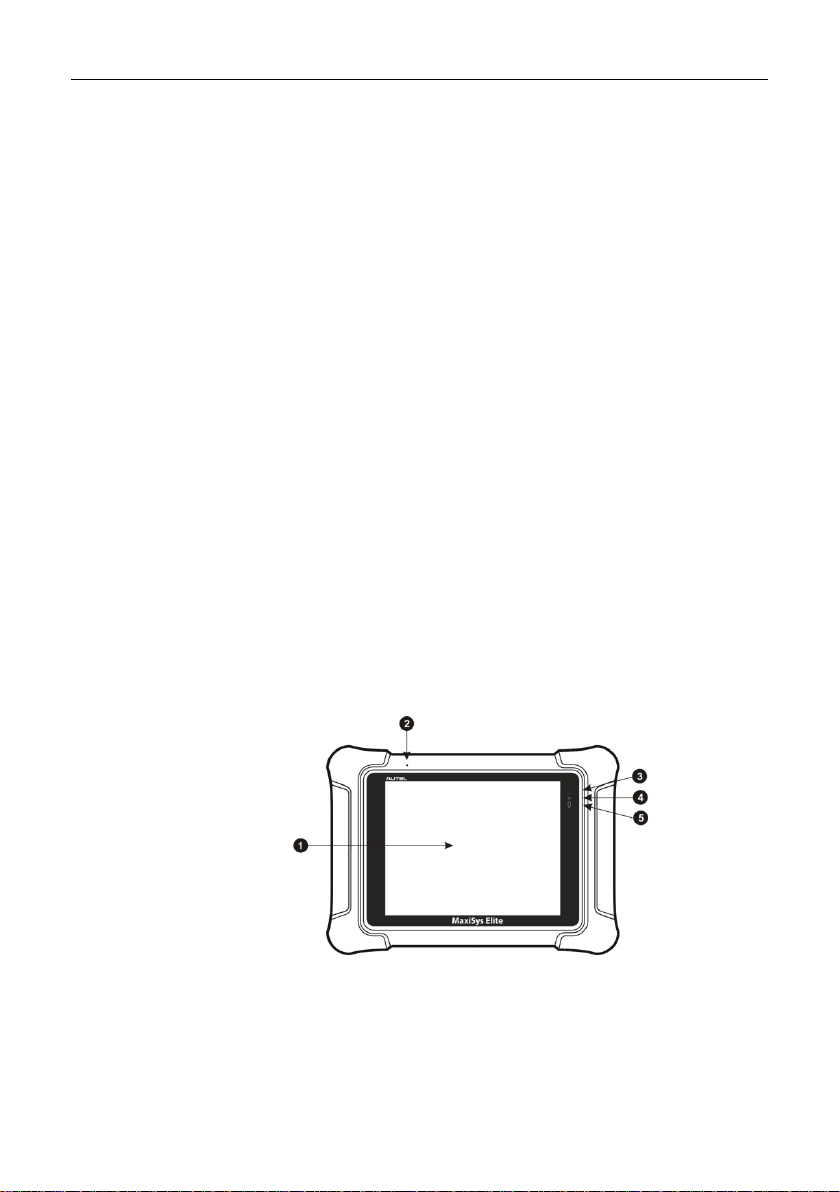
Figure 2-1 MaxiSys Display Tablet Front View
1. 9.7” Retina display with capacitive touch screen
2. Microphone
3
Page 11
General Introduction MaxiSys Display Tablet
3. LED Breath Light – indicates battery level & charging status
4. Front Camera
5. Ambient Light Sensor – detects ambi ent brightness
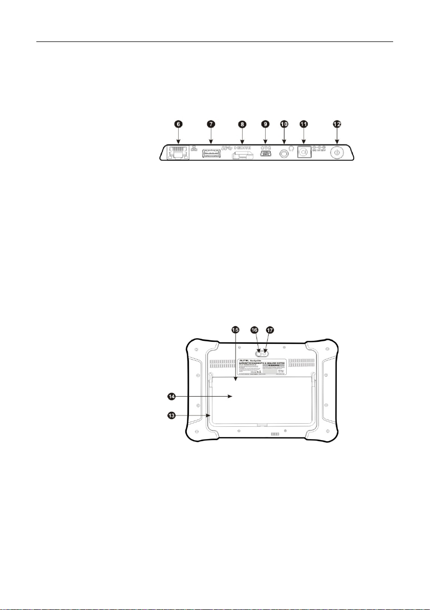
Figure 2-2 MaxiSys Display Tablet Top View
6. Ethernet Port
7. USB Port – for VCI connection
8. HDMI Port
9. Mini USB OTG Port
10. Head Phone Jack
11. DC Power Supply Input Port
12. Lock/Power Button – turns the device on & off with long press, or locks
the screen with short press
Figure 2-3 MaxiSys Display Tablet Back View
13. Collapsible Stand – extends from the back to allow hands-free viewing of
the display tablet at a 30-degree an gle
14. Removable Battery
15. SIM Card Slot – optional module
16. Camera Lens
17. Camera Flash
4
Page 12

General Introduction MaxiSys Display Tablet
Capacitive touch screen
2.1.2 Power Sources
The MaxiSys Elite can receive power from any of the following sources:
Rechargeable Battery Pack
AC/DC Power Supply – using power adapter or docking station
Vehicle Power
Rechargeable Battery Pack
The display tablet can be powered with the r echargea ble b atter y, which if fully
charged can provide sufficient power for about 6.5 hours of continuous
operation.
AC/DC Power Supply
The display tablet can be powered f rom a wall socket using the AC/ DC po wer
adapter or the docking station. The AC/DC power supply also charges the
battery pack.
Vehicle Power
The display tablet can be powered from the ci garette lighter or other suitable
power port on the test vehicle through a direc t cable connection. The vehicle
power cable connects to the DC power supply port on the top side of the
display unit.
2.1.3 Technical Specifications
Item Description
Operating System Android 4.3 Jelly Bean
Processor
Memory 2GB RAM & 32GB Embedded Memory
Display 9.7” Retina display with 2048X1536 resolution &
NVIDIA Tegra® 4 (4-PLUS-1 Quad-core
Processor) 1.8GHz with ARM Cortex – A15 CPU
5
Page 13

General Introduction MaxiSys Display Tablet
Item
Description
4G Mobile Netwo rk (Optional)
Front: 2.0 Megapixel
sensor, Air Gesture
/standard headset
2.0, TP 1.6, SAE J1939, SAE J1708,
Fault-Toler ant C AN
Connectivity 802.11a/b/g/n/ac WIFI
Version 2.1 3Mbs Bluetooth
RJ45 Ethernet Connection
3.0 USB (2.0 Compat ible)
HDMI 1.4a
SD Card (Support up to 32GB)
Camera
Rear: 8.0 Megapixel, Autofocus with Flashlight
Sensors Ambient Light Sensor, G-
Sensing
Audio Input/Output Microphone
Dual Speakers
3-Band 3.5 mm stereo
jack
Power and Battery 3.7V/13600mA H Li thium-polymer battery
DC/12V/3A Power Supply
Input Voltage DC/12V/3A
Power Consumption Max 20W
Operating Temperature -10 to +55°C
Storage Temperature -20 to +70°C
Dimensions (W x H x D) 309 X 225 X 35 (mm)
Weight 1.59 kg
Protocols
ISO 9142-2, ISO 14230-2, ISO 15765-4, K/ L lins,
Flashing Code, SAE-J1850 VPW, SAE-J1850
PWM, CAN ISO 11898, Highspeed, Middlespeed,
Lowspeed and Singlewire CAN, GM UART, UART
Echo Byte Protocol, Honda Diag-H Protocol, TP
6
Page 14
General Introduction VCI – J2534 ECU Programming Device
2.2 VCI – J2534 ECU Progra m ming De vi ce
2.2.1 Functional Description
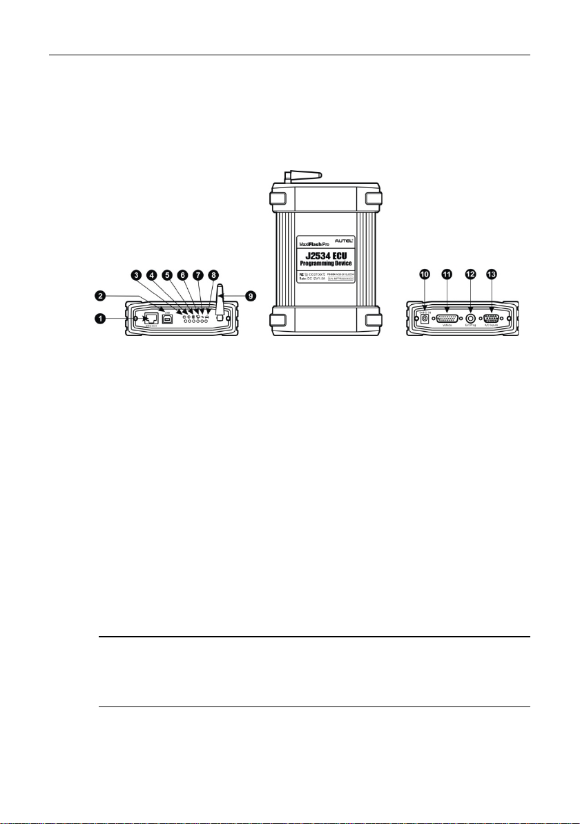
Figure 2-4 J2534 ECU Programming Device
1. Ethernet Port
2. USB Port
3. Power LED - illuminates solid green when po wered on
4. Error LED - illuminates solid red when seri ous hardware failure occurs
5. Bluetooth LED - illuminates solid green when connected with the
MaxiSys display tablet through Bluetooth communication
6. Ethernet LED - illuminates solid green when connected with the MaxiSys
display tablet or an existing LAN v i a the Ethernet serial cable
7. USB Status Light - illuminates solid green when the device is properly
connected and communicating with t he MaxiS ys displ ay tab let or the P C
via the USB cable
8. Vehicle LED - flashes green when communicating with the vehicle’s
network
IMPORTANT: Do not dis connect the reprogramming device while this stat us
light is on! If the flash reprogramming procedure is interrupted while the
vehicle’s ECU is blank or only partially programmed, the module may be
unrecoverable.
9. Bluetooth Antenna
10. DC Power Supply Input Port
7
Page 15

General Introduction VCI – J2534 ECU Programm ing Device
11. Vehicle Data Connector (DB26-Pin MVCI)
12. External Progr am ming Voltage Output Port
13. A/D Input Port
J2534 Reprogramming Capability
The J2534 ECU Programming Device is a SAE J2534-1 & -2 compliant
PassThru reprogramming interface device. Using the updated O EM software,
it is capable of replacing the existing software/firmware in the Electronic
Control Units (ECU), programm ing new ECUs and fixing software-controlled
drivability issues and emission issues.
Communication
The J2534 ECU programming device supp orts Bluetooth, Ethernet and US B
communication. It can transmi t vehicl e data to t he MaxiS ys displ ay tabl et with
or without a physical connection. The working range of the transmitter through
Bluetooth communication is 755 feet (about 230 m). A signal lost due to
moving out of range automatically restores itself when the display tablet unit is
brought closer to the VCI unit.
2.2.2 Power Sources
The J2534 programming device can rec eive power from bot h of the following
sources:
Vehicle Power
AC/DC Power Supply
Vehicle Power
The J2534 programming device op erates on 12-volt vehicle power, which it
receives through the vehicle data connection port. The device powers on
whenever it is connected to an OBD II/EOBD com pliant data link connector
(DLC). For non OBD II/ EOBD compliant vehicles, the device can be powered
from a cigarette lighter or other suitable po wer port on the test vehicle using
the auxiliary power cable.
AC/DC Power Supply
The J2534 programming device can be power ed from a wall socket us ing the
AC/DC power adapter.
8
Page 16
General Introduction Docking Station
Communications
Ethernet: RJ45 Ethernet connec tion
Input Voltage Range
6 VDC to 26 VDC
Supply Current
300 mA @ 6 VDC
Operating Temperature
0°C to +60°C (ambient)
Storage Temperature
-65°C to +100°C (ambient)
Dimensions (L x W x H)
183.8 x 135.5 x 41 (mm)
Weight
0.54 kg (1.20 lb)
2.2.3 Technical Specifications
Item Description
Bluetooth
USB 2.0
200 mA @ 12 VDC
110 mA @ 24 VDC
NOTE: For additi onal please refer to the accompanied us er manual for the
J2534 ECU Programming Device.
2.3 Docking Station
2.3.1 Functional Description
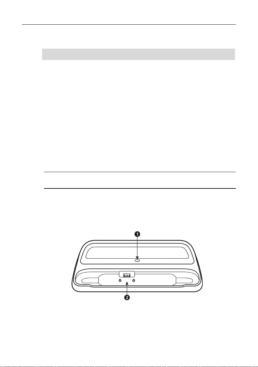
Figure 2-5 Docking Station
9
Page 17

General Introduction Accessory Kit
Operating Temperature
-10°C to +55°C (ambient)
Storage Temperature
-40°C to +85°C (ambient)
Dimensions (L x W x H)
326.5 x 128.5 x 49 (mm)
Weight
0.79 kg (1.74lb)
1. DC Power Supply Input Port – connects to the AC/DC adapter for power
supply
2. Charging Dock – holds the MaxiSys tablet while providing optimum
visibility and convenient charging
NOTE: Please make sure no small metal or other conduct ive parts are around
the Charging Dock to avoid short c i r cuit damage to the device.
2.3.2 Technical Specifications
Item Description
Input Voltage
2.4 Accessory Kit
2.4.1 Main Cable
The VCI device can be powered through the Main Cable whe n connected to
an OBD II/EOBD compliant vehicle. The Main Cable c onnects the VCI device
to the vehicle’s data link connector (DLC), throug h which the VCI device can
transmit vehicle data to the MaxiSys display tablet.
DC/12V/3A
Figure 2-6 Main Cable – 1.5 m in length
10
Page 18
General Introduction Accessory Kit
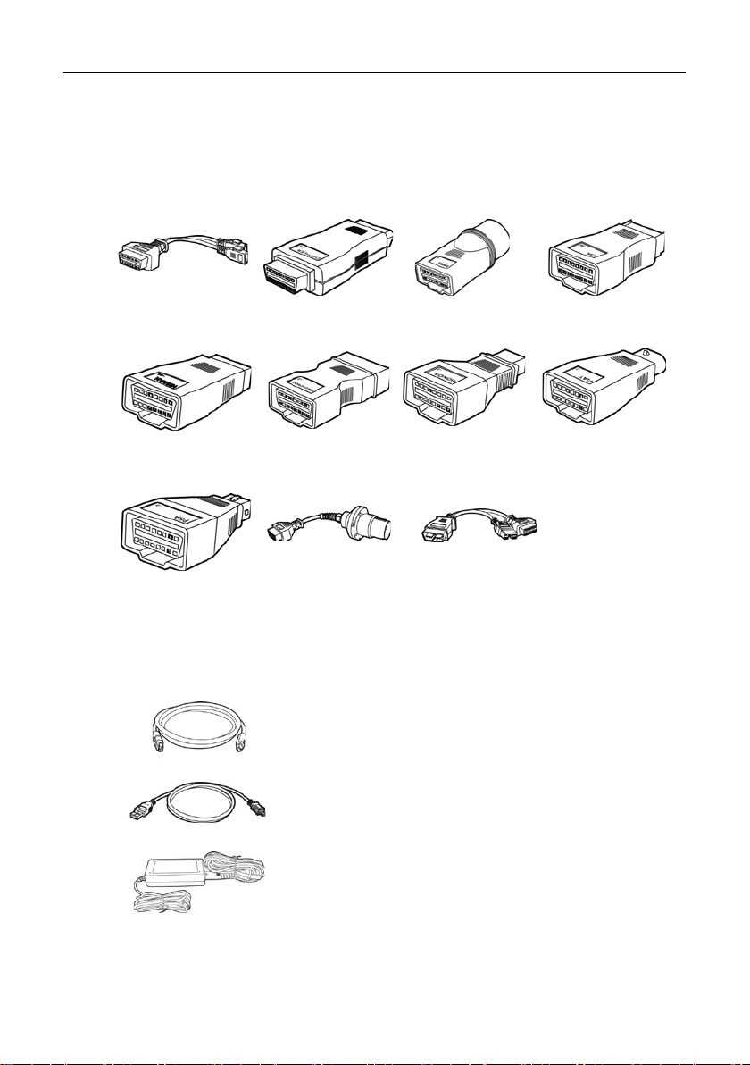
2.4.2 OBD I Adapters
The OBD I adapters are for Non-OBD II vehicles. The adapter used depends
on the type of vehicle make being t ested. The most common adapters are
shown below.
VW/Audi-2+2
Nissan-14
PSA-2
Chrysler-16 BMW-20 Kia-20
GM/Daewoo-12
Benz-38
2.4.3 Other Accessories
Standard 2.0 USB Cable
Connects the display tablet to t he V CI unit.
Mini USB Cable
Connects the display tablet to t he P C.
Honda-3
Mitsubishi/Hy
undai-12+16
Fiat-3
AC/DC External Power Adapter
Connects the display tablet t o the external DC power
port for power supply.
11
Page 19

General Introduction Accessory Kit
programming device through connection to the
s cigarette lighter receptacle, as some
to the
Lighter Fuse
Screwdriver
Compact Disc (CD)
Includes the User Manual, Printing Services Program
and Update Application, etc.
Ethernet Serial Cable
Connects the display tablet to t he V C I unit.
Cigarette Lighter
Provides power to the display tablet or the J2534
vehicle’
non-OBD II vehicles cannot provide power via the
DLC connection.
Clipper Cable
Provides power to the display tablet or the J2534
programming device, through connection
vehicle’s battery.
A safety device for the cigarette lighter.
Unscrews the rear cover of the display tablet for easy
replacement of the battery or Mini S D card.
12
Page 20
Chapter 3 Getting Started
Make sure the MaxiSys Display Tablet has a charged battery or is connected to the DC
power supply (see 2.1.2 Power Sour ces on page 5).
3.1 Powering Up
Press the Lock/Power button on the top right side of the display tablet to
switch the unit on. The system boot s up, and shows the lock screen. Press
and drag the inner ring to the edge of the circle to unlock the screen; the
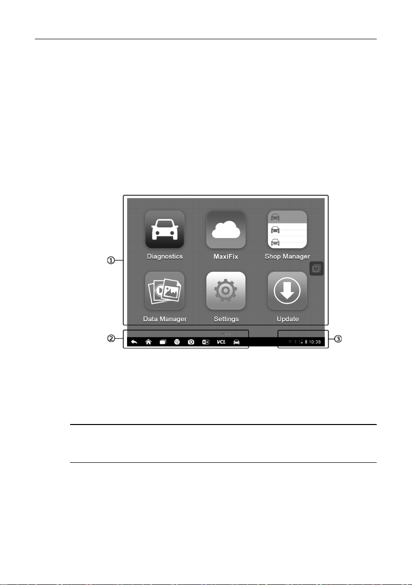
MaxiSys Job Menu is shown.
Figure 3-1 Sample MaxiSys Job Menu
1. Application Buttons
2. Locator and Navigation Buttons
3. Status Icons
NOTE: The screen is locked by default when you first turn on the display tablet.
It is recommended to lock the s creen to pr otect inf ormati on in the s ystem and
reduce battery usage.
Almost all operations on the display tablet are controlled through the touch
screen. The touch screen navigation is menu driven, which allows you to
quickly locate the test procedure, or data that you need, through a seri es of
choices and questions. Detailed descriptions of the menu structures are found
in the chapters for the various applications.
13
Page 21
Getting Started Powering Up
Allows you to set the MaxiSys system settings,
Allows you to edit and save works hop i nformation
Launches the Support platform which
3.1.1 Application Buttons
The Application buttons configure the MaxiSys for the type of operation or
activity to be performed. The table below gives brief descriptions of the
available applications.
Use the stylus pen or your finger tip to select an application from the Job
Menu.
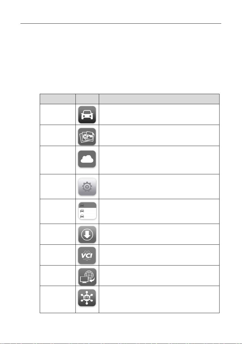
Table 3-1 Applications
Name Button Description
Diagnostics
Data
Manager
MaxiFix
Settings
Shop
Manager
Update
VCI
Manager
Remote
Desk
Configures the unit to operate as a diagnostic
tool. See Diagnostics Operations on page 19.
Opens the organization system for saved data
files. See Data Manager Operations on page 63.
Launches the MaxiFix platform which provides the
most compatible and abundant repair techn iques
and diagnostics database. See MaxiFix
Operations on page 68.
and to view the general information about the
Display Tabl et. See
78.
and customer data, as well as reviewing test
vehicle history records. See
Operations on page 83.
Checks for the latest update available for the
MaxiSys system, and performs updating
procedures. See Update Operati ons on page 91.
Establishes and manages Bluetooth or wired
connections to the VCI device. See VCI Manager
Operations on page 93.
Configures your unit to receive remote support
using the TeamViewer application program. See
Remote Desk Operations on page 97.
Settings Operations on page
Shop Manager
Support
synchronizes Autel’s on-line service base station
with the MaxiSys tablet. See
on page 99.
14
Support Operations
Page 22
Getting Started Powering Up
Opens the camera with short press; takes and
stored in the Data
Allows you to adjust the brightness of the
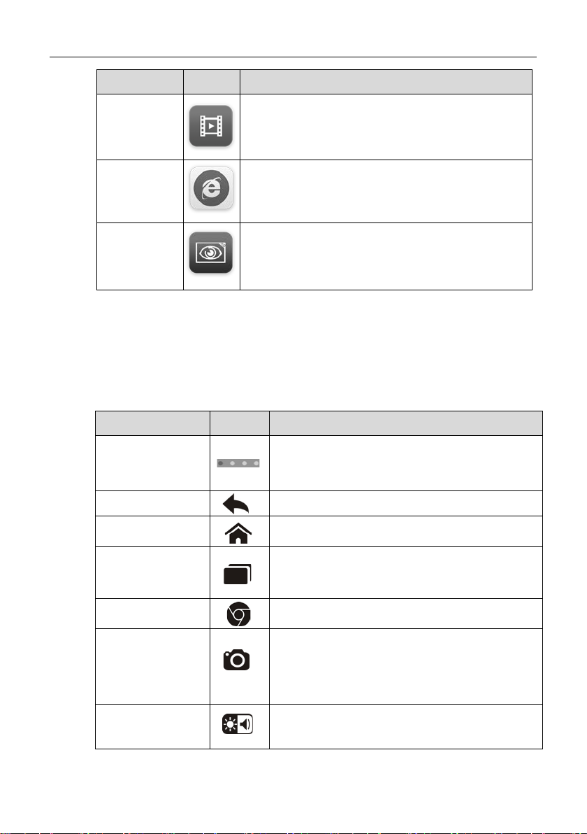
Name Button Description
Allows you to store and play technic al tutorial and
Training
Quick Link
Digital
Inspection
training videos about the device us age or vehicle
diagnostic techniques. See Training Operations
on page 109.
Provides associated website bookmarks to allow
quick access to pro duct update, service, support
and other information. See Q uick Link Operati ons
on page 111.
Configures the unit to operate as a video scope
device by connecting to an Imager hea d cable for
close vehicle inspections. See Digital Inspection
Operations on page 112.
3.1.2 Locator and Navigation Buttons
Operations of the Navigation buttons at the bottom of the screen are described
in the table below:
Table 3-2 Locator and Navigation Buttons
Name Button Description
Indicates the location of the sc reen. S wipe the
Locator
screen left or right to view the previous or ne xt
screen.
Back
Home
Recent Apps
Chrome
Camera
Display & Sound
Returns to the previous screen.
Returns to Android System’s Home screen.
Displays a list of applications that are currently
working. To open an app, touch it. To remove
an app, drag it downwards.
Launches the Chrome browser.
saves screenshot image with lon g press. The
saved files are autoManager application for later reviews. See
Data Manager Operations on page 63.
screen and the volume of the audio output.
15
Page 23
Getting Started Powering Down
Name
Button
Description
up a Multi Task
bookmarks. Tapping a specific
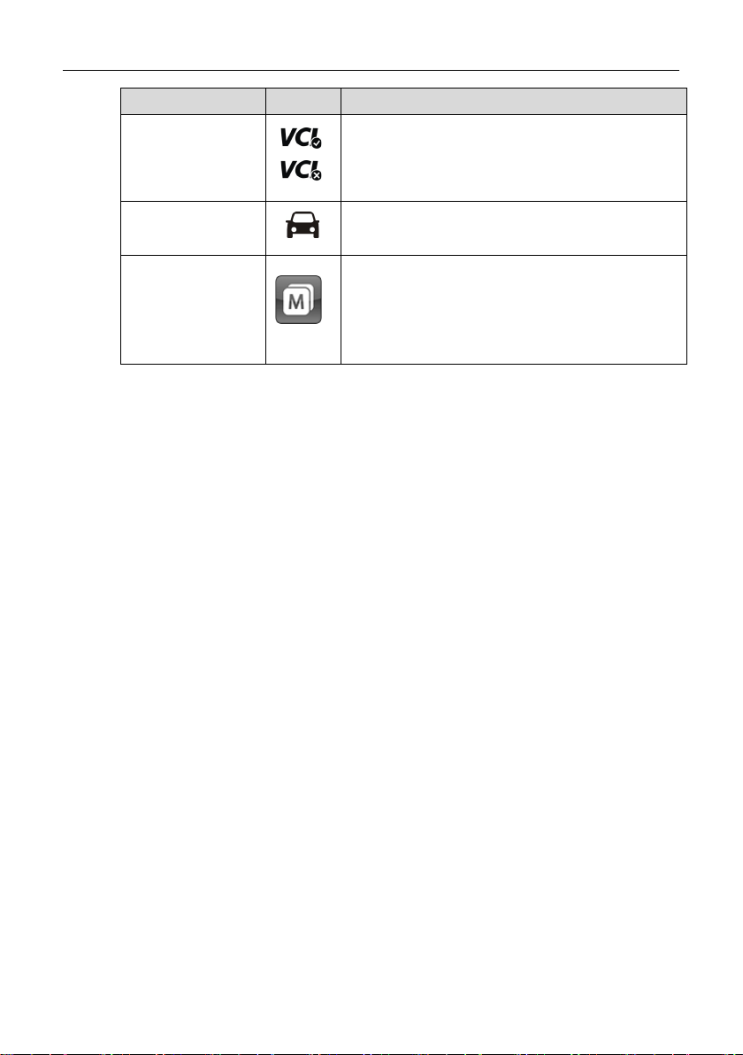
Opens the VCI Manager application. T he tick
VCI
icon at the bottom right corner indicates the
display tablet is communicating with the VCI
device, otherwise a cross icon displays.
MaxiSys
Shortcut
Multi Task
To use the camera:
1. Tap the Camera button. The camera screen opens.
2. Focus the image to be captured in the vi ew finder.
3. Tap the inner blu e circle. The view finder now shows the captured
picture and auto-saves the taken photo.
4. Tap the thum bnail image on the top right corner of the screen to
view the stored image.
5. Tap the Back or Home button to exit the camera application.
Refer to Android documentation f or additional information.
3.1.3 System Status Icons
These are the standard status icons of the Android operating system. Your
MaxiSys display tablet is a fully functional Android Pad. Refer to Android
documentation for additional i nformation.
Returns to the MaxiSys operation interface
from other Android applications.
Tapping this button opens
menu, on which displays the active running
application
bookmark enables you to switch direct l y to the
selected application screen.
3.2 Powering Down
All vehicle communications must be terminated before shutting down the
MaxiSys display tablet. A warning message displays if you attempt to shut
down while the VCI unit is communicating with the vehicle. Forcing a shut
down while communicating may lead to ECM problems on some vehicles. Exit
the Diagnostics application before powering down.
16
Page 24

Getting Started Install Computer Software
To power down the MaxiSys tablet:
1. Press and hold the Lock/Power Button.
2. Tap OK; the tablet will turn off in a few seconds.
3.2.1 Reboot System
In case of system crash, pres s and hold t he Lock/ Power b utton f or 8 seco nds
to reboot the system.
3.3 Installing Computer Software
The MaxiSys Elite Diagnostic Platform allows you to realize some of its
functions on a computer to enhance capabilities and improve user experience.
To realize these functions on a computer, you need to install certain software.
There are two Setup.exe program packages contained in the CD provided
with the MaxiSys Elite tool kit. The package includes the following
applications:
1. PC Link - launches a Printing Services program which receives and
allows editing the files sent from the MaxiSys tablet for printing
2. Driver Program - setup driver program for the VCI dev ice
3. Network Configuration Program and Update Agent - network
configuration program and firmware update agent for the VCI device
To install the Setup.exe program
1. Insert the CD into the CD-ROM of the computer. The driver
installation wizard will load m om entarily.
2. Click on Next on the welcome page.
3. Click the Change button, and select a destination folder to install the
program, and click Next to continue. Or directly click Next to
continue without changing the default installation folder.
4. Click Install and the Setup.e xe program will be installed ont o the
computer.
3.3.1 Printing Operation
This section describes how to receive file from the MaxiSys tablet and perform
17
Page 25

Getting Started Install Computer Software
printing through the computer:
To perform printing through the computer
1. Install the PC Link (Printi ng Services program) to the computer.
2. Make sure the displ ay tablet is connect ed to the computer net work,
either via Wi-Fi or LAN, before printing. See 7.1.3 Printing Setting on
page 79 for more information.
3. Run the Printing Services program on the computer.
4. Tap the Print button on the toolbar displayed in various applicatio ns
of the M axiSys system. A temporary file will be created and s ent to
the computer for printing.
5. Click the Printer Server tab on the top of the program interface on
the computer, and wait for the printing file to load.
6. Click the Print button to s tart printing.
NOTE: Make sure the computer installed with the Printing Services program is
connected to a printer.
Refer to the accompanied user man ual for the corresponding VCI d evice for
detailed information about the operat ion of the net work confi guration pr ogram
and/or the update agent.
18
Page 26

Chapter 4 Diagnostics Operations
By establishing a data link to the electronic control systems of the vehicle being
serviced through the VCI device, the Diagnostics application allows you to retrieve
diagnostic information, view live data parameters, and perform active tests. The
Diagnostics application can access the electronic control module (ECM) for various
vehicle control systems, such as engine, transmission, antilock brake system (ABS),
airbag system (SRS) and more.
4.1 Establishing Vehicle Communication
The Diagnostics operations requ ire connecting the MaxiSys Elite Diagnostic
Platform to the test vehicle through t he VCI device using t he main cable, and
test adapters (for non-OBD II vehicles). To establish proper vehicle
communication to the MaxiSys display tablet, you need to perform the
following steps:
1. Connect the VCI device to the vehicle’s DLC for both communication and
power source.
2. Connect the VCI device to the MaxiSys display tablet via Bluetooth
pairing, USB connection, or Ethernet connection.
3. When these are done, check the VCI navigation button at the bottom bar
on the screen, if the button displays a gr een tick icon at the lower right
corner, the MaxiSys Elite diagnostic platform is ready to start vehicle
diagnosis.
4.1.1 Vehicle Connection
The method used to connect the VCI dev ice to a vehicle’s DLC depends on
the vehicle’s configuration as follows:
A vehicle equipped with an On-board Diagnostics Two (OBD II)
management system supplies both communication and 12-volt power
through a standardized J-1962 DLC.
A vehicle not equipped with an OBD II management system supplies
communication through a DLC connection, and in some c ases supplies
12-volt power through the cigarette light er receptacle or a connection t o
the vehicle battery.
19
Page 27

Diagnostics Operations Establishing Vehicle Communication
OBD II Vehicle Connection
This type of connection only requires the main cable without an y additional
adapter.
To connect to an OBD II vehicle
1. Connect the main cable’s female adapter to the Vehicle Data
Connector on the VCI device, and tighten the captive screws.
2. Connect the cable’s 16-pin male adapter to the vehicle’s DLC, which
is generally located under the vehicle dash.
NOTE: T he vehicle’s DLC is not always located under the dash; refer to
the user manual of the test vehicle for additional connection information.
Non-OBD II Vehicle Connection
This type of connection requires both the main c able and a required OBD I
adapter for the specific vehicle bei ng serviced.
There are three possible conditions for Non-OBD II vehicle connection:
DLC connection supplies both comm uni cation and power.
DLC connection supplies communication and power is to be supplie d v i a
the cigarette lighter connection.
DLC connection supplies communication and power is to be supplie d v i a
connection to the vehicle battery.
To connect to a Non-OBD II Vehicle
1. Connect the main cable’s female adapter to the Vehicle Data
Connector on the VCI device, and tighten the captive screws.
2. Locate the required OBD I adapter and connect its 16-pin jack to the
main cable’s male adapter.
3. Connect the attache d OBD I adapter to the vehicle’s DLC.
NOTE: Some adapters ma y have more than one adapter or may have test
leads instead of an adapter. Whatever the case, make the proper connectio n
to the vehicle’s DLC as required.
20
Page 28
Diagnostics Operations Establishing Vehicle Communication
To connect the ci garette lighter
1. Plug the DC power connector of the cigarette lighter into the DC
power supply input port on the device.
2. Connect the male connect or of the ci garett e light er int o the vehic le’s
cigarette lighter receptacle.
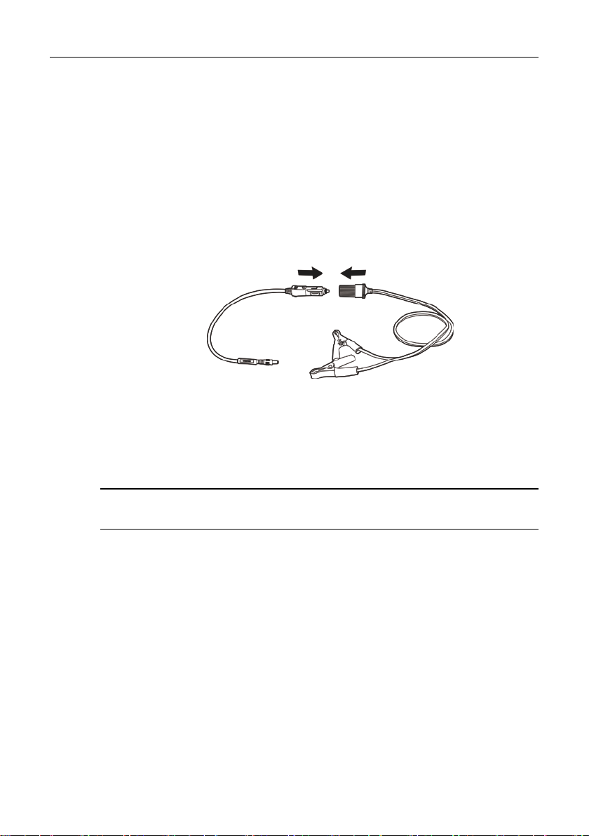
To connect the cl ipper cable
1. Connect the tubular plug of the clipper cable t o the male connector
of the cigarette lighter.
Figure 4-1 Connection between Cigarette Lighter and C lipper Cable
2. Plug the DC power connector of the cigarette lighter into the DC
power supply input port of the J2534 programming device.
3. Connect the clipper cable to the vehicle’s battery.
NOTE: After the VCI device is successfully connected to the vehicle, the
Power LED on the device illuminates , and a brief beep sound will be heard.
4.1.2 VCI Connection
After the VCI device is proper ly connected to the vehicle, the Power LED on
the VCI device illuminates solid green light, and is ready to establish
communication with the MaxiSys di splay tablet.
The J2534 ECU Programming Devic e, which comes with the MaxiSys Elite
tool kit, supports 3 commun ication methods with the MaxiSys disp lay tablet:
Bluetooth, USB, and Ethernet connection.
21
Page 29

Diagnostics Operations Establishing Vehicle Communication
Pairing Up via Bluetooth
Among all methods, Bluetooth pairing is recommended as the first choice for
the communication between the Ma xiSys display tablet and the VCI device.
The working range for Bluetooth communication is about 755 feet (230 m); this
means you can perform vehicle diagnosis freely around the workshop with
greater convenience.
If you use more than one VCI device to connect to the test vehicles when
customers are many, you can perform vehicle diagnosis on various veh icles
conveniently, by pairing the MaxiSys display tablet separately to each of t he
VCI devices connected to the different test vehicles, via Bluetooth, without th e
need to repeat the plugging and unplugging proce dure, which is unavoidable
through traditional wired connection, thus s aves you more time and provid es
more efficiency.
To pair up the MaxiSys display tablet with the VCI device via
Bluetooth
1. If not already done, power up the MaxiS ys display tablet.
2. Select the VCI Manager application from the MaxiSys Job Menu.
3. When the VCI Manager application is opened, the device
automatically starts s canning for available VCI devices around for
Bluetooth pairing. The found devices are listed in the Setting
section on the right side of the screen.
NOTE: If no VCI device is found, this may indicate that the signal strength
of the transmitter is too weak to be det ected. In this c ase try to get closer
to the device, or reposition the VCI device, and remove all possible
objects that causes signal interference. When these are done, tap the
Scan button at the top right corner to st ar t searching again.
4. The device name may display as Maxi suffixed with a serial number.
Select the required device for pairing.
5. When paring is successfully done, the conn ection status displayed
to the right of the device name is shown as Paired.
6. Wait for a few seconds, and the VCI button on the system
Navigation bar at the bottom of the screen shall display a green tick
icon, indicating the displa y tablet is connected to the VCI device,
and is ready to perform vehicle diagnosis.
Refer to 10.1 Bluetooth Pairing on page 94 for additional information.
22
Page 30

Diagnostics Operations Establishing Vehicle Communication
USB Cable Connection
The USB cable connection is a simple and quick way to establish
communication between the MaxiSys display tablet an d the VCI device. After
properly conn ecting the USB cable fr om the tablet to the VCI device, the VCI
navigation button at the bottom bar of the screen shows a green tick icon in a
few seconds, and the USB LED on the VCI device illuminates solid green light,
indicating the connection between the devices is successful.
The MaxiSys Elite diagnostic platform is now ready to perform vehicle
diagnosis.
NOTE: Since the USB connection provides the most stable and fastest
communication, it is highly recommended to apply this communication method
when operating ECU programming or coding. When all the three
communication methods are applied at the same time, the MaxiSys system
will use the USB communication as the default priority.
Wired Connection via Ethernet
This section describes the general proc edure to connect the tablet with the
J2534 ECU programming device via Ethernet connection. To establish
successful communication, you need to s et up the network configuration on
the display tablet.
To connect the MaxiSys display tablet with the VCI device via
Ethernet
1. If not already done, power up the MaxiS ys display tablet.
2. Connect the MaxiSys Display Tablet to the J2534 ECU
programming device with the accompanied Ethernet serial cable.
3. Select the VCI Manager application from the MaxiSys Job Menu.
4. Select the Wired Network option o n t he Con nect io n Mod e list. The
Ethernet Setting screen displays on the right section.
5. Select a connection type:
DHCP – obtains the LAN IP address automatically
Manual – allows you to enter IP address manually
23
Page 31

Diagnostics Operations Establishing Vehicle Communication
6. If Manual is selected, you need to set the IP address on your own.
NOTE: If you are not sure about the sp ecific IP address values, please
contact your network administrator.
7. Tap Apply to set up the wired network connection.
When the wired network is successful ly co nnected, the connection status is
displayed as Connected, and the two status lights at the corners alongside the
Ethernet Ports on the display tabl et illuminat e. The solid am ber light in dicates
steady connection, and the flashing green light indicates active
communication, between the unit s. The VCI navigation button at the bottom
bar shall display a green tick icon after a few seconds, indicating the MaxiS ys
Elite diagnostic platform is ready to perform vehicle diagnosis.
Refer to 10.2 Wired Network Connection on page 95 for additional information.
NOTES: After the MaxiSys Elite diagnostic platform has successfully
established communication with the vehicle, the VCI device makes a long
beep sound for confirmation.
4.1.3 No Communication Message
A. If the MaxiSys Display Tablet is not connected to the VCI device, an
“Error” message displays. An “Error” message indicates the display
tablet is not communicating with the VCI device, and so cannot gain
access to the vehicle control module. In this c ase, you need to do the
following check-ups:
Check if the VCI device is powered on.
In cas e of wireless connection, check if the network is configured
correctly, or if the right device has been paired.
If during the diagnosis process, the communication is suddenly
interrupted due to the los s of signal , check if there is an y object that
causes signal interruption.
Check if t he V CI device is properly positioned. It is r ecom m ended t o
put the VCI device with the front side u p.
Try standing closer t o the VCI device to obta in more stable signals,
and faster communication speed.
24
Page 32

Diagnostics Operations Getting Started
In cas e of wired connection, check the cable connection between
the display tablet and the VCI device.
Check if the green LED on the VCI device is illuminated for
Bluetooth, Ethernet, or USB.
Check if the Error LED on the VCI device is on, this may indicate
there is a communication error between the devices, in this case try
re-establishing the connection again; if this does not work, there
may be a hardware problem wit h the devi ce, in this cas e contact for
technical support.
B. If the VCI device is unable to establish a co mmunication link, a prompt
message displays with check inst ructions. The following conditions are
the possible causes for this massag e to display:
T he VCI device is unable to es tablish a co mmunication link with the
vehicle.
You’ve selected a system for testing that t he vehic le is not equ ipped
with.
There is a loose connection.
There is a blown vehicle fuse.
There is a wiring fault on the vehicle, or the data c able or adapter.
There is a circuit fault in the data cable or adapter.
Incorrect vehicle identification was entered.
4.2 Getting Started
Prior to first use of the Diagnostics application, the VCI device must be
synchronized with the MaxiSys Displa y Tablet to establish a comm unication
link. See VCI Manager Operations on page 93.
4.2.1 Vehicle Menu Layout
When the VCI device is properly connected to the vehicle, and paired to the
MaxiSys Display Tablet, the platform is ready to start vehicle diagnosis. Tap on
the Diagnostics application but ton on the M axiS ys Job Menu, the scre en then
opens the Vehicle Menu.
25
Page 33
Diagnostics Operations Getting Started
Displays the stored test vehic le history records.
recorded during
on page 84.
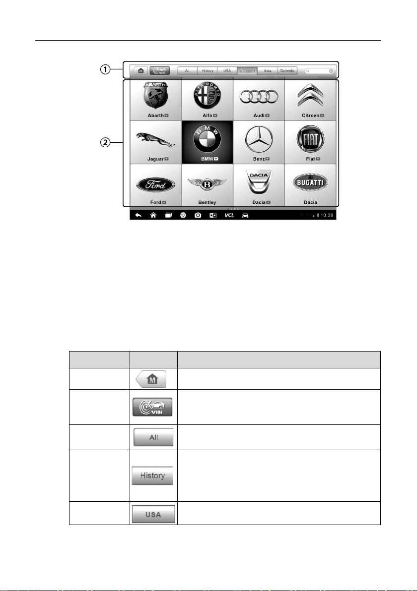
Figure 4-2 Sample Vehicle Menu Screen
1. Top Toolbar Buttons
2. Manufacturer Buttons
Top toolbar Buttons
The operations of the Toolbar buttons at the top of the screen are listed and
described in the table below:
Table 4-1 Top Toolbar Buttons
Name Button Description
Home
VIN Scan
All
History
USA
Returns to the MaxiSys Job Menu.
Touching this button opens a dropdown list; tap
Auto Detect for auto VIN detection; tap Manual
Input to enter VIN manually.
Displays all the vehicle makes in the vehicle
menu.
This option provides you direct access to the
previously tested vehicle
previous test sessions. See 8.1 Vehicle History
Displays the USA vehicle menu.
26
Page 34

Diagnostics Operations Vehicle Identification
allowing you to manually enter the specific
Name Button Description
Europe
Asia
Domestic
Search
Cancel
Displays the European vehicle m enu.
Displays the Asian vehicle menu.
Displays the Domestic vehicle menu.
Touching th is button opens the virtual k eyboard,
vehicle make required.
Touching this button exits the search screen, or
cancels an operation.
Manufacturer Buttons
The Manufacturer buttons display the various vehicle logos and the brand
names. Select the required manufacturer button after the VCI device is
properly connected to the test vehicle to start a diagnostic session.
The small envelop icon displa ys beside the vehicle brand name is tappable,
touching which displays an attached PDF file, showing relevant information,
such as vehicle coverage, function list, and so on for the corresponding
vehicle make.
4.3 Vehicle Identification
The Maxisys Elite diagnostic system supports four methods for Vehicle
Identification.
1. Auto VIN Scan
2. Manual VIN Input
3. Manual Vehicle Selection
4. OBD Direct Entry
4.3.1 Auto VIN Scan
The MaxiSys Elite diagnostic system features t he latest VIN-based Auto VI N
Scan function to identify CAN vehicles in just one touch, which allows the
technician to quickly detect vehicles, scan all the di agnosable ECU s on ever y
vehicle and run diagnostics on the selected system.
27
Page 35

Diagnostics Operations Vehicle Identification
To perform Auto VIN Scan
1. Tap the Diagnostics application button from the MaxiSys Job Menu.
The Vehicle Menu displays. (Figure 4-2)
2. Tap the VIN Scan button on the top toolbar.
3. Select Auto Detect. The tester starts VIN s canning on th e vehicle’s
ECU. Once the test vehicle is successfully identified, the system will
guide you to the Vehicle Diagnostics screen directly.
Figure 4-3 Sample Vehicle Diagnostics Screen
4.3.2 Manual VIN Input
For some vehicles that do not support the Auto VIN Scan function, the
MaxiSys Elite diagnostic system all o ws you to ent er t h e ve hicle VI N man u all y,
or simply take a photo of the VIN stick er for quick vehicle identification.
To perform Manual VIN Input
1. Tap the Diagnostics application button from the MaxiSys Job Menu.
The Vehicle Menu displays. (Figure 4-2)
2. Tap the VIN Scan button on the top toolbar.
3. Select Manual Input.
4. Tap the input box and enter the correct VIN.
28
Page 36

Diagnostics Operations Vehicle Identification
Figure 4-4 Manual VIN Input
5. Tap Done. The vehicle will be identified in a f ew seconds, and onc e
the matching is successful, the system will guide you to the Vehicle
Diagnostics screen directly. (Figure 4-3)
6. Tap Cancel to exit Manual Input.
4.3.3 Manual Vehicle Selection
When the vehicle’s VIN is not automatic ally retrievable through the vehic le's
ECU, or the specific VIN is unkno wn, you can choose to select the vehicle
manually.
There are generally three ways to enter t he vehicle information:
A. Step-by-step Vehicle Selection
This mode of vehicle selection is menu driven; you simply follow the scr een
prompts and make a series of cho ices. Each selection you make advances
you to the next screen. A Back button at the lower right corner of the screen
returns you to the previous sc reen. Exact proced ures may var y somewhat by
various vehicles being serviced.
29
Page 37
Diagnostics Operations Vehicle Identification
B. Manual Vehicle Entry
This mode allows you to manually enter and save specific vehicle information,
such as PCM Part Number, Vehicle Calibration Number, or Tear Tag. This
function enables direct access to the vehic le's ECM and saves your time of
doing step-by-step entry selections.
To perform Manual Vehicle Entr y - take Ford for example
1. Tap the Diagnostics application button from the MaxiSys Job Menu.
The Vehicle Menu displays. (Figure 4-2)
2. Tap the USA or the All button on the top toolbar.
3. Select the Ford button from the vehicle menu.
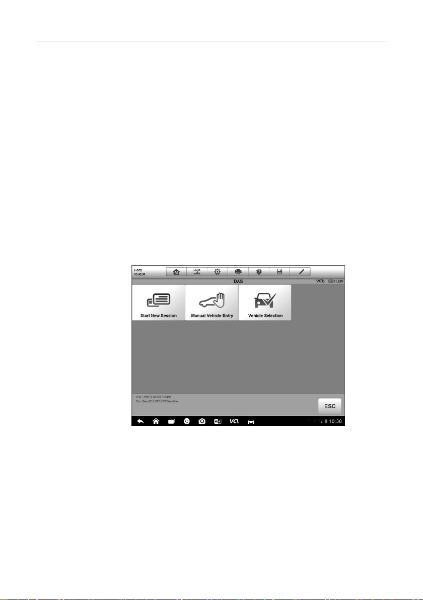
4. Select Manual Vehicle Entry from the Vehicle Selection Menu.
(Figure 4-5) A series of information screen displays, tap Yes to
continue.
Figure 4-5 Sample Vehicle Selection Menu
5. Select one of the three entries in the option screen - PCM Part
Number, Calibration Number or Tear Tag.
6. Take the PCM Part Number entry for example; you need to fill up
the accurate vehicle information in the input boxes.
30
Page 38

Diagnostics Operations Vehicle Identification
Figure 4-6 PCM Part Number Input Screen
7. Tap OK to continue when the input is done. A confirming screen
showing the Vehicle Information displays.
8. Check if the vehicle information is correct, and then from the
confirming screen, select:
a) Yes to continue.
b) No to return to the vehicle selection menu.
9. Select Yes and the vehicle diagnostics screen disp lays.(Figure 4-3)
C. Auto Vehicle Entry
Some vehicles provide an auto scan feature, which allows you to skip the
step-by-step vehicle identification proc edure and retrieve the specific vehicle
information from the vehicle’s ECU directly.
To perform Auto Vehicle Entry - take Ford for example
1. Tap the Diagnostics application button from the MaxiSys Job
Menu. The Vehicle Menu displays. (Figure 4-2)
2. Tap the USA or the All button on the top toolbar.
3. Select the Ford button from the vehicle menu.
4. Select Start New Session from the vehicle selection menu. A
confirming screen showing the Vehicle Information displays.
31
Page 39

Diagnostics Operations Navigation
5. Check if the vehicle information is correct, and then from the
confirming screen, select:
a) Yes to continue.
b) No to return to the vehicle selection menu.
6. Select Yes and the Vehicle Diagnostics screen displays. (Figure
4-3)
4.3.4 Alternative Vehicle Identification
Occasionally, you may identify a test vehicle that the tester does not recognize;
the database does not support, or has some unique characteristics that
prevent it from communicating with the tester through the normal chan nels. In
these instances, you are provided with t he OBD direct entry, thr ough which
you can perform generic OBD II or EOBD tests. See 4.9 Generic OBD II
Operations on page 57 for additional inf ormation.
4.4 Navigation
This section describes how to navigate the Diagnostics interface and select
test options.
4.4.1 Diagnostics Screen Layout
The Diagnostics screens typically inc l ude four sections. (Figure 4-7)
Figure 4-7 Sample Diagnostics Screen
32
Page 40

Diagnostics Operations Navigation
Touching this button allows you to exit the
for operations of
1. Diagnostics T oolbar
2. Status Information Bar
3. Main Section
4. Functional Buttons
Diagnostics Toolbar
The Diagnostics toolbar contains a number of buttons that allow you to print or
save the displayed data and make other c ontrols. T he table below provid es a
brief description for the operati ons of the Diagnostics toolbar buttons :
Table 4-2 Diagnostics Toolbar Buttons
Name Button Description
Home
Vehicle
Swap
Returns to the MaxiSys Job Menu.
diagnostic session of the currently identified test
vehicle, and returns you to the vehicle menu s creen
to select another vehicle for test i ng.
Settings
Opens the setting screen. See S ettings Operations
on page 78.
Saves and prints a copy of the displa yed data. See
Print
3.3.1 Printing Operation for additional information
on page 17.
Help
Provides instructions or tips
various diagnostic functions.
Tapping this button opens a submenu, on which
there are 3 options available to save the displayed
data.
Tap Save This Page to take a screenshot
image
Save
Tap Save All Data to save a PDF file (mostly
used to save data that cover more than 1
page)
Tap Start Saving to record a video clip (only
available for recording Live Data or special
graph data)
All saved data are stored in the Data Manager
application for later reviews. See Data Manager
Operations on page 63.
33
Page 41

Diagnostics Operations Navigation
Records the communication data and ECU
104 for detailed information.
Name Button Description
information of the test vehicle. The saved dat a can
Data
Logging
be reported and sent to the technical c enter via the
internet.
You c an go to the Support application to follo w up
the processing progress, see Data Logging on page
Send
To perform data printing in Diagnostics
Tapping this button submits the Data Logging report
to the technical center via the internet.
1. Tap the Diagnostics application button from the MaxiSys Job Menu.
The Print button on the diagnostic toolbar is available throughout
the whole Diagnostics operations.
2. Tap Print whenever you want to make a printing. A drop-down menu
appears.
a) Print This Page – prints a screenshot copy of the current
screen
b) Print All Page – prints a PDF copy of all displayed data
3. A temporary file will be created and sent to the computer for printing.
4. When the file is transferred successfully, a confirmation message
displays.
NOTE: Make sure the disp lay tablet is connected to the computer network,
either via Wi-Fi or LAN, before printing. For more instructions on printing, see
3.3.1 Printing Operation on page 17 for det ailed information.
To submit Data Logging reports in Diagnostics
1. Tap the Diagnostics application button from the MaxiSys Job Menu.
The Data Logging button on the diagnostic toolbar is available
throughout the whole Diagnostic s operations.
34
Page 42

Diagnostics Operations Navigation
2. Tap the Data Logging button whenever you want to commit
recording for the system communicat ion data. The button displays
blue during the active recording proc es s.
3. Tap the button again to finish recording. A submission form will
display to let you fill in the report inf or mation.
4. Tap the Send button to submit the report form via the internet, a
confirmation message displays when sending is successful.
Status Information Bar
The Status Information Bar at the top of the Main Section displays the
following items:
1. Menu Title – indicates the menu subject of the Main Section
2. VCI Icon – indicates the communication status between the tablet and
the VCI device
3. Battery Icon – indicates the batt ery status of the VEHICLE
Main Section
The Main Section of the screen varies depending on the sta ge of operations.
The main section can show vehicle identific ation selections, the main menu,
test data, messages, instructio ns and other diagnostic information.
Functional Buttons
The displayed Functional Buttons at this section of the screen varies
depending on the stage of operations. T hey can be used to navigate, save or
clear the diagnostic data, exit scanning as well as make other functional
controls. The functions of these buttons will be introduced respect ively in the
following sections of the corres ponding test operations.
4.4.2 Screen Messages
Screen messages appear when additi onal in put is ne eded bef ore pr oceed ing.
There are mainly three types of on-screen messages as to their purposes:
Confirmation, Warning, and Error.
35
Page 43

Diagnostics Operations Main Menu
Confirmation Messages
This type of messages usually displays as an “Information” screen, which
informs you when you are about to perform an ac tion that cann ot be rever sed
or when an action has been initiated and your confirmation is needed to
continue.
When a user-response is not required to continue, the message displays
briefly before automatically di sappearing.
Warning Messages
This type of messages informs you when completing the selected act ion may
result in an irreversible change or loss of data. The typical example f or this is
the “Erase Codes” message.
Error Messages
Error message s inform you when a system or procedural error has oc curred.
Examples of possible errors inc lude a disconnected cable or commu nication
interruption due to certain reasons.
4.4.3 Making Selections
The Diagnostics application is a menu driven program that prese nts a series
of choices one at a time. As you se lect from a menu, the next menu in the
series displays. Each selection narrows the focus and leads to the desired test.
Use your fingertip or the stylus pen t o m ake menu selections.
4.5 Main Menu
The Diagnostics application allows you to establish a data link to the electronic
control system of the test vehicle via the VCI device for vehicle diagnosis,
service or programming. You can operate functional tests, retrieve vehicle
diagnostic information such as tr ouble codes, event codes and live d ata, and
perform ECU reprogramming, for various vehicle control systems, such as
engine, transmission, ABS and more.
36
Page 44

Diagnostics Operations Diagnosis
The Vehicle Diagnostics screen (Figure 4-3) has three main options:
1. Diagnosis – a comprehensive section which includes all available
functions: reading, clearing, s aving and printing diagnostic information,
as well as performing active tests and special functions
2. Service – a separate section designed to perform vehicle scheduled
service and maintenance, such as to reset t he service lights and perform
calibration for various systems
3. Programming/Coding – a separat e section designed for quick access
to ECU reprogramming operations
After a section is selected an d the tablet establishes c ommunication with the
vehicle via the VCI device, the corresponding function menu or selection
menu displays.
4.6 Diagnosis
There are two options available when accessing the Diagnosis section:
1. Auto Scan – starts auto scanning for all the available systems on the
vehicle
2. Control Units – displays a selection menu of all available control units of
the test vehicle
Auto Scan
The Auto Scan function performs a comprehensive scanning over all the
systems on the vehicle’s ECU in order to locate fault systems and retrieve
DTCs. The sample operation interface of Auto Scan displays as below:
37
Page 45

Diagnostics Operations Diagnosis
Figure 4-8 Sample Auto Scan Operation Screen
1. Navigation Bar
2. Main Section
3. Functional Buttons
Navigation Bar
1. List Tab – displays the scanned data in list f ormat
2. Tree Tab – display the scanned data in system distribution diagram
format
3. Progress Bar – indicates the test progress
Main Section
A. List Tab
Column 1 - displays the system numbers
Column 2 - displays the scanned s ystems
Column 3 - displays the diagnostic marks indicating different conditions
of the test result:
-!-: Indicates that the scanned system may not support the code
reading function, or there is a communication error between the tester
and the control system.
38
Page 46

Diagnostics Operations Diagnosis
selected.
-?-: Indicates that the vehicle cont rol system has been detected, but
the tester cannot accurately locate it.
Fault | #: Indicates there is/are detected fault code(s) present; “#”
indicates the number of the detected faults.
Pass | No Fault: Indicates the system has passed the scanning
process and no fault has been detected.
B. Tree Tab
The tree tab screen displays a system distribution diagram of the vehicle
control modules. The scanned system which has passed scanni ng with
no fault is shown in blue font; whereas the scanned system that has
been detected with fault present is shown in red font.
Tab the
perform further diagnosis and other test activities. A Function Menu
screen (Figure 4-9) shall then display.
Functional Buttons
The table below provides a brief description of the Functional Buttons’
operations in Auto Scan:
Table 4-3 Functional Buttons in Auto Scan
Name Description
Back Returns to the previous screen or e xit Auto Scan.
Pause
OK
Quick Erase
Report Displays the diagnostic data in the report form.
Save
>E A button to the ri ght of the system item, on which you want to
○
Suspends scanning and changes to show the Continue
button.
Confirms the test result, and continues to the system
diagnosis after selecting the re quir ed system by t apping
the item in the Main Section.
Deletes codes. A warning message screen will display
to inform you of possible data loss when thi s function is
Saves the diagnostic session as a history record, this
allows you to quickly restore access to the test systems.
39
Page 47

Diagnostics Operations Diagnosis
Control Units
This option allows you to manually locat e a r equi red co nt rol s ystem f or t esti ng
through a series of choices. You simply follow the menu driven procedure, and
make proper selection each time; the program will guides you to the diagnostic
function menu after a few choices you’ve made.
Figure 4-9 Sample Function Menu Screen
The Function Menu options vary slightly by different vehicles. The function
menu may include:
ECU Information – provides the retrieved ECU information in detail.
Selecting opens an information sc reen.
Read Codes – displays detailed information of DTC records retrieved
from the vehicle control module.
Erase Codes – erases DTC records and other data from the ECM.
Live Data – retrieves and displays l ive data and parameters from the
vehicle’s ECU.
Active Test – provides specif ic subsystem and component tests. This
selection may appear as Actuators, Actuator Test, or Function Tests,
etc., and the tests options vary depending on the manufacturer and
model.
40
Page 48

Diagnostics Operations Diagnosis
Special Functions – provides component adaptation or variant coding
functions for custom configurations, and also allows you to reprogram
adaptive values for certain components af ter making repair s. Depending
on the test vehicle, this selection may sometimes appear as Control
Unit Adaptations, Variant Coding, Configuration or something similar.
NOTE: With the diag nostic toolbar o n top of the screen t hroughout the whole
diagnostic procedures, you are allowed to make various controls of the
diagnostic information at anyti me, such as printing and saving the displayed
data, get help information, or perfor m data logging, etc.
To perform a diagnostic function
1. Establish communication with the test vehicle via the VCI dev i c e.
2. Identify the test v ehicle by selecting from the menu options.
3. Select the Diagnosis section.
4. Locate the required system for testing by Auto Scan or through
menu driven selections in Control Units.
5. Select the desired test from the Function Menu.
4.6.1 ECU Information
This function retrieves and displays the specific information for the tested
control unit, including unit type, version numbers and other specifications. The
sample ECU Information screen dis pl ays as below:
Figure 4-10 Sample ECU Information Screen
41
Page 49

Diagnostics Operations Diagnosis
1. Diagnostics Toolbar Buttons – see Table 4-2 Diagnostics Toolbar
Buttons on page 33 for detailed description s of the operations for each
button.
2. Main Section – the left column displays the item names; the right
column shows the specifications or descriptions.
3. Functional Button – In this case, only a Back (or sometimes an ESC)
button is available; tap it to exit after viewing.
4.6.2 Read Codes
This function retrieves and displays the DTCs from the vehicle’s control
system. The Read Codes screen varies for each vehicle being tested, on
some vehicles, freeze frame data can also be retrieved for viewing. The
sample Read Codes screen displays as below:
Figure 4-11 Sample Read Codes Screen
1. Diagnostics Toolbar Buttons – see Table 4-2 Diagnostics Toolbar
Buttons on page 33 for detailed descripti ons of the operations for each
button.
2. Main Section
Code C olumn – displays the retrieved codes from the vehicle.
42
Page 50

Diagnostics Operations Diagnosis
Status Column – indicates the status of the retr ieved codes.
Descr i ption Column – detailed descriptions for the retrieved codes.
Sno wflake Icon – only displays when freeze frame data is availab le
for viewing; Selecting displays a data screen, which looks very
similar to the Read Codes interface, therefore same operation
method may be applied.
3. Functional Button – in this case, only a Back (or sometimes an ESC)
button is available; tap it to return to the previous screen or exit the
function.
4.6.3 Erase Codes
After reading the retrieved c odes from the vehicle and cert ain repairs have
been carried out, you can decide to erase the codes from the vehicle using
this function. Before performi ng this function, mak e sure the vehicle’s ignitio n
key is in the ON (RUN) position with the engine off.
To erase codes
1. Tap Erase Codes from the Function Menu.
2. A warning message displays to inform you of data loss when th is
function is applied.
a) Tap Yes to continue. A confirming screen displays when the
b) Tap No to exit.
3. Tap ESC on the confirming screen to exit Erase Codes.
4. Check the Read Codes function agai n to ensure the operation is
successful.
4.6.4 Live Data
When this function is selected, the screen displays the data list for the
selected module. The items avail able for any control module vary from one
vehicle to another. The parameters display in the order that they are
transmitted by the ECM, so expect variation between vehicles.
operation is successfully done.
43
Page 51

Diagnostics Operations Diagnosis
Gesture scrolling allows you to quickly move through the data list. Simply
touch the screen and drag your finger up or down to reposition the parameters
being displayed if the data covers more than one screen. T he figure below
shows a typical Live Data screen:
Figure 4-12 Sample Live Data Screen
1. Diagnostics Toolbar Buttons – tap the drop-down button at the top
center of the screen displays the toolbar buttons. See Table 4-2
Diagnostics Toolbar Buttons on page 33 for detaile d descriptions of the
operations for each button.
2. Main Section
Name Column – this column displays the parameter names.
a) Check Box - tap the check box at the left side of the parameter
name to make selection of an item. Tap the check box again to
deselect the item.
b) Drop-down Button – tapping the drop-down button at the right
side of the parameter name opens a submenu, which provi des
various choices for data display mode.
Value Column – displays the values of the parameter items.
Range Column - displays the minimum and the maximum limit
value.
Unit Column – displays the unit for the parameter values.
44
Page 52

Diagnostics Operations Diagnosis
To change the Unit mod e, tap the Setting button on the top toolbar
and select a required mode. See 7.1.1 Unit on page 78 for more
information.
3. Display Mode
There are 4 types of display modes available for dat a viewing, allowing
you to view various types of parameters in the most suitable way for
better data check-ups.
Tapping th e drop-down button on the right side of the parameter name
opens a submenu. There are 4 buttons to configure the data display
mode, plus one Help button on the right, tappable when additional
information is available for your reference.
Each parameter item displays the selected mode independently.
Analog Gauge Mode – displays the parameters in form of an analog
meter graph
Text Mode – this is the def ault mode which displays the parameters in
texts and shows in list format
NOTE: Reading of stat us parameters, such as a switch reading, which
are mostly in word form, like ON, OFF, ACTIVE, and ABORT, etc., can
only be displayed in Text Mode. Whereas reading of value parameters,
such as a sensor reading, can be disp la yed i n t ext mod e an d ot h er gra ph
modes.
Waveform Graph Mode – displays the parameters in waveform graphs
When displaying this mode, thr ee control buttons will appear on the r ight
side of the parameter item, allowing you to manipulate the display status.
Text Button – resumes Text Display Mode
Scale Button – changes the scale values, which are displayed
below the waveform graph. There ar e 4 scales available: x1, x2,
x4 and x8.
Zoom-in Button – tap once to display the selected data graph in
full screen
Digital Gauge Mode– displays the parameters in form of a digit al gauge
graph
Full Screen Display – this option is only available in the waveform graph
mode, and mostly used in Graph Merge status for data comparison.
There are three control buttons available on the top right side of the
screen under this mode.
45
Page 53

Diagnostics Operations Diagnosis
Edit Button – tapping this button opens an edit window, on which
you can set the waveform color and the line thickness displayed
for the selected parameter item.
Scale Button - changes the scale values, which are displayed
below the waveform graph. There ar e 4 scales available: x1, x2,
x4 and x8.
Zoom-out Button – exits full screen display.
To edit the waveform color and line thickness in a data graph
1. Select 1 to 3 parameter items to display in Waveform Graph mode.
2. Tap the Zoom-in Button on the right to display the d ata graph in
full screen.
3. Tap the Edit Button, an edit window appears.
4. Select a parameter item on the left c ol umn.
5. Select a desired sample color from the second column.
6. Select a desired sample line thickn es s from the right column.
7. Repeat step 4-7 to edit the waveform for each parameter item.
8. Tap Done to save the setting and exit, or tap Cancel to exit witho ut
saving.
4. Functional Buttons
The operations of all the available function al buttons on Live Data screen
are described below:
Back – returns you to the previous screen or exit the function.
Record – starts recording the retrieved live data; the recorded data is
then stored as a video clip in the Data Manager application for future
reviews. This function could be triggered automatically at preset threshold
value or manually as you choose, and the triggering mode and record
duration can be configured in the S etting mode of Live Data.
Freeze – displays the retrieved data in freeze mode.
Previous Frame – Moves to the previous frame in the freeze data.
Next Frame – Moves to the next frame in the freeze data.
Resume – this button appears when the Record or Freeze function is
applied. Tapping this button stops data recording, or exit freeze data
mode, and resumes normal data display mode.
46
Page 54

Diagnostics Operations Diagnosis
Flag – this button appears when the Record funct ion is applied. Tapping
this button sets flags for the recorded data at points wherever you choose,
when playing back the recorded video clip later in Data Manager, the
preset flag will enable a popup to allow input of text to take notes.
Clear Data –tapping which clears all previously retrieved parameter
values at a cutting point whenever you choose.
To Top – moves a selected data item to the top of the list.
Graph Merge – tap this button to merge selected data graphs (for
Waveform Graph Mode only). This function is very useful when makin g
comparison for different parameters.
NOTE: This mode supports Graph Merge for 2 to 3 parameter item s onl y,
so select no less than 2 or more than 3 items each time when making
graph merge.
To cancel Graph Merge mode, tap the drop-down button on the
right side of the parameter name, and select a data display mode.
Show Selected/Show All – tap this option to exch ange be tween the t wo
options; one displays the selected paramet er items, the other displays al l
the available items.
Setting – tapping this butt on opens a s etting sc reen, which allows you t o
set the trigger mode, recording durati on, and various threshold v alues fo r
data recording, and make other controls.
Figure 4-13 Sample Setting Mode in Live Data
47
Page 55

Diagnostics Operations Diagnosis
There are 4 navigation buttons on top of the Setting mode screen.
Range Button – displays the configuration screen on which you can
set the threshold values, an upper limit and a lower limit, for
triggering the buzzer alarm. This function is only applied to the
Waveform Graph display mode.
a) MIN – tapping which opens a virtual keyboard, allows you to
enter the required lower limit value
b) MAX – tapping which op ens a virtual keyboard, allo ws you to
enter the required upper limit valu e
c) Buzzer Alarm – switches the alarm on and off. The alarm
function makes a beep sound as a reminder whenever the data
reading reaches the preset mini mum or maximum point
To set threshold limits for the parameter values
1. Tap the Setting functional button at the bottom of the Live Data
screen.
2. Tap the Range navigation button.
3. Select a parameter item on the left c olumn, or enter the item
name in the Search bar.
4. Tap on the righ t side of the MIN button, and enter the required
minimum value.
5. Tap on the right side of the MAX button, and enter the required
maximum value.
6. Tap the ON/OFF button on t he right side of the Buzzer Alarm
button to turn it on or off.
7. Tap Done to save the setting and return to the Live Data
screen; or tap Cancel to exit without saving.
If the threshold limits ar e successfully set, two horizontal lines now
appear on eac h of the data graphs (when Waveform Graph M ode is
applied) to indicate the alarming point. The threshold lines are shown
in different colors than the waveform of the parameters for distinction.
Record Button – displays the configuration screen for Record
Setting, on which you can set the trigger type, duration and trigger
point for the data recording funct i on.
48
Page 56

Diagnostics Operations Diagnosis
a) Trigger T ype – sets the trigger mode for data recording, mainly
of two kinds: Manual and Auto. There are four options
available:
1) Manual – allows you to manually start and stop data
recording
2) DTC – auto triggers data recording when any DTC is
detected
3) DTC Check Mode – auto triggers data recording when
certain pre-selected DTC types are detected
4) Parameter – auto triggers data recording when any
parameter value reaches the preset threshold
b) Duration – sets the recording time (for Auto trigger mode only)
c) Trigger Point – reserves a relative percentage of a record
length before the data record ing start point for reference (for
Auto trigger mode only)
To perform setting for live data record
1. Tap the Setting functional button at the bottom of the Live Data
screen.
2. Tap the Record navigation button.
3. Tap the
A
>E A button on t he right of Trigger Type bar and select
○
the required trigger mode.
4. Tap the
A
>E A butt on on the right of Duration bar and select a
○
length of time.
5. Tap the
A
>E A button on the right of Trigger Point bar and select
○
a relative percentage of a record length t o be reserved before
the data recording start point.
6. Tap Done to save the setting and return to the Live Data
screen; or tap Cancel to cancel without saving and exit Setting.
Done Button - confir ms and saves the setting, and returns you to
the Live Data screen.
Cancel Button – cancel the setting operation, and returns you to
the Live Data screen.
49
Page 57

Diagnostics Operations Diagnosis
4.6.5 Active Test
The Active Test function is used to access vehicle-specific subsystem and
component tests. Available test var y by manufacturer, year, and model, and
only the available tests display in t he menu.
During an active test, the tester outputs commands to the ECU in order to
drive the actuators. This test determines the integrity of the system or parts by
reading the engine ECU data, or by monit oring the o peratio n of the act uators,
such as switching a solenoid, relay, or switch, between two operating st ates.
Selecting Active Test opens a menu of test options that varies by make and
model. Selecting a menu option activates the test. Follow all screen
instructions while performing t ests. How and what inf orm ation is present ed on
the screen varies according t o the type of test being perfor med. Some toggl e
and variable control tests dis play Act ive Test Controls at the top of the screen
with data stream information below, or vice versa.
Figure 4-14 Sample Active Test Screen
The functional buttons at the lower right corner of the Active Test screen
manipulate the test signals. The oper ational instructio ns are displayed on t he
main section of the test screen. Simply foll ow the on-screen instructions and
make appropriate selections to complete the tests. Each time when an
operation is successfully executed, message such as “Com mand Finished”,
“Activation Successful”, or something similar displays.
Tap the ESC functional button to exit the test when finish ed.
50
Page 58

Diagnostics Operations Diagnosis
4.6.6 Special Functions
These functions perform various component adaptations, allowing you to
recalibrate or configure certain components after making repairs or
replacement.
The main section of the Adaptation Operation screen displays a list of
operational and vehicle status information, which mainly consists of four parts:
1. The first part in the top line shows the descript ion of the operation being
performed, and the execution status is displayed on the right, such as
Completed, or Activated, etc.
2. The second part shows the preconditi ons or requirements for executing
the operation being selected.
3. The third part displays the current conditions of the vehicle control module
being learned for comparison to the preconditions suggested by the
second part. If the current condition of t he control module is out of the
suggested limit value, you must adjust t he vehicle condition to meet the
requirement.
4. The last part displays the instruction of how to use the functional button at
the lower right corner of the screen t o m anipulate the teach-in operations.
Figure 4-15 Sample Adaptation Operation Screen
51
Page 59

Diagnostics Operations Service
Read the information carefully and check the vehicle condition accordingly,
when you are sure that the vehicle is ready to perform the adaptation, simpl y
follow the instruction provided to make appropriate selections. When the
operation is done, an execution s tat us m essa ge suc h as Co mplet e d, F inish ed
or Successful, displays.
Tap the ESC button to exit the function.
4.7 Service
The Service section is specially desig ned to provide you quick access to the
vehicle systems for various scheduled service and maintenance performances.
The typical service operation screen is a series of menu driven executive
commands. By following the on-screen instructions to select appropriate
execution options, enter correct values or data, and perform necessary
actions, the system will guide you through the complete performance for
various service operations.
The most commonly performed service functions include:
Oil Reset Service
TPMS Programming Service
EPB Service
ABS/SRS Services
SAS Calibration Service
DPF Regeneration Service
4.7.1 Function Descriptions
This section describes the main functions for vehicle service:
Oil Reset Service
This function allows you to perform reset for the Engine Oil Life system , which
calculates an optimal oil life change interval depend on the vehicle driving
conditions and climate. The Oil Life Remi nd er m ust be r eset ever y tim e the oil
is changed, so the system can calculate when the next oil change is required.
Tire Pressure Monitor System (TPMS) Service
This function allows you to quickly look up the tire sensor IDs from the
vehicle’s ECU, as well as to perform TPMS programming and reset
procedures after tire sensors ar e replaced.
52
Page 60

Diagnostics Operations Programming and Coding
Electric Parking Brake (EPB) Service
This function has a multitude of usages to maintain the electronic braking
system safely and effectively. The applications include deactivating and
activating the brake control system, assisting with brake fluid cont rol, opening
and closing brake pads, and setting brakes after disc or pad replacement, etc.
ABS/SRS Services
This function allows you to perform various bi-directional tests to check the
operating conditions of both the Anti-lock Braking System and the
Supplemental Restraint System , such as Automated Bleeding, Pump Motor
Test, and checking Module information, etc.
Steering Angle Sensor (SAS) Service
This service function allow you to per form calibration for the Steering Angle
Sensor, which permanently stores the current steering wheel position as the
straight-ahead position in the steer ing angle sensor EE PROM. On succ essful
completion of the calibration, the steering angle sensor fault memory is
automatically cleared.
DPF Regeneration Service
The Diesel Particulate Filter service function performs the regeneration
procedure which is the DPF cleaning op eration to clear the bloc kage through
continuous burning of the particulat e matter captured in the DPF filter. If the
DPF light on the vehicle comes on and you successfully complete a DPF
regeneration cycle, you will noti c e that the DPF light will automatically t urn off.
4.8 Programming and Coding
Since the introduction of OBD II and leading up to modern Hybri ds and EVs,
computers and software in cars have be en expanding at an expon ential rate.
In-car software is becoming one of the leading needs for service, and updating
software may be the only way to fix some of these issues:
Drivability
Fuel Efficiency
Power Loss
Fault Codes
Durability of Mechanical Parts
53
Page 61

Diagnostics Operations Programming and Coding
The Programming and Coding functio n is used to re-flash the vehicl e control
modules, it allows you to update t he computer software on the vehicle to the
latest version, as well as to reprogram ada ptive data for certain components
after making repairs or replacements.
NOTE: The programming function can only be applied through connection
with the J2534 programming device, which serves as a PassThru interface to
establish communication with and tr ans fer data to the vehicle’s ECU.
Available programming or coding operations var y by t he tes t vehic l e, an d o nl y
the available operations display in the menu.
There are two general types of programming operations:
A. Coding – also kno wn as Teach-in Progra m, Component Adaptation or
something similar, is used to reprogram adaptive data for vehicle cont rol
modules after repairs or replacements of vehicle parts.
B. Reprogramming Operations – downloads new version of software
subscription from the on-line server database through internet access
(this procedure is done automatically when the M axiSys display tabl et is
connected to the internet, so there is no need to check for software
subscriptions yourself), and repro grams the newest software version to
the vehicle’s ECU.
NOTE: Ensure that the display tablet is connected to the Internet before
applying the ECU programmi ng function, so that the display ta blet is able to
obtain access to the manufacturer’s server for update service.
Selecting the Programming or Coding function opens a menu of operation
options that varies by make and model. Selec ting a menu opt ion eith er sho ws
a programming interface or opens anot her menu of ad ditional choices. Follo w
all screen instructions whi le p erfor min g the p rogram mi ng or coding operations.
How and what information is presented on t he screen vari es according to the
type of operation being performed.
54
Page 62

Diagnostics Operations Programming and Coding
Variant Coding
Figure 4-16 Sample Variant Coding Screen
The main section of the Variant Coding screen displays a list of vehicle
components and the coding inform ation which mainly consists of three pa rts:
1. The top line on the list displays the instruction of how to use the
functional button at the lower right corner of the screen to manipulate the
coding operations.
2. The second part under the top line of the list displays all available
systems for coding on the left side, and the coding data or value on the
right side.
3. The bottom line of the main section displays the functional buttons, which
allow you to manipulate the operat ion.
Check the vehicle condition and the coding infor mation carefully, and use the
functional button to edit Codes for the corresponding components, tap Send
when you finish edit for all the items. When the operation is done, an
execution status message such as C ompleted, Finished or Successful, may
display.
Tap the ESC button to exit the function.
55
Page 63
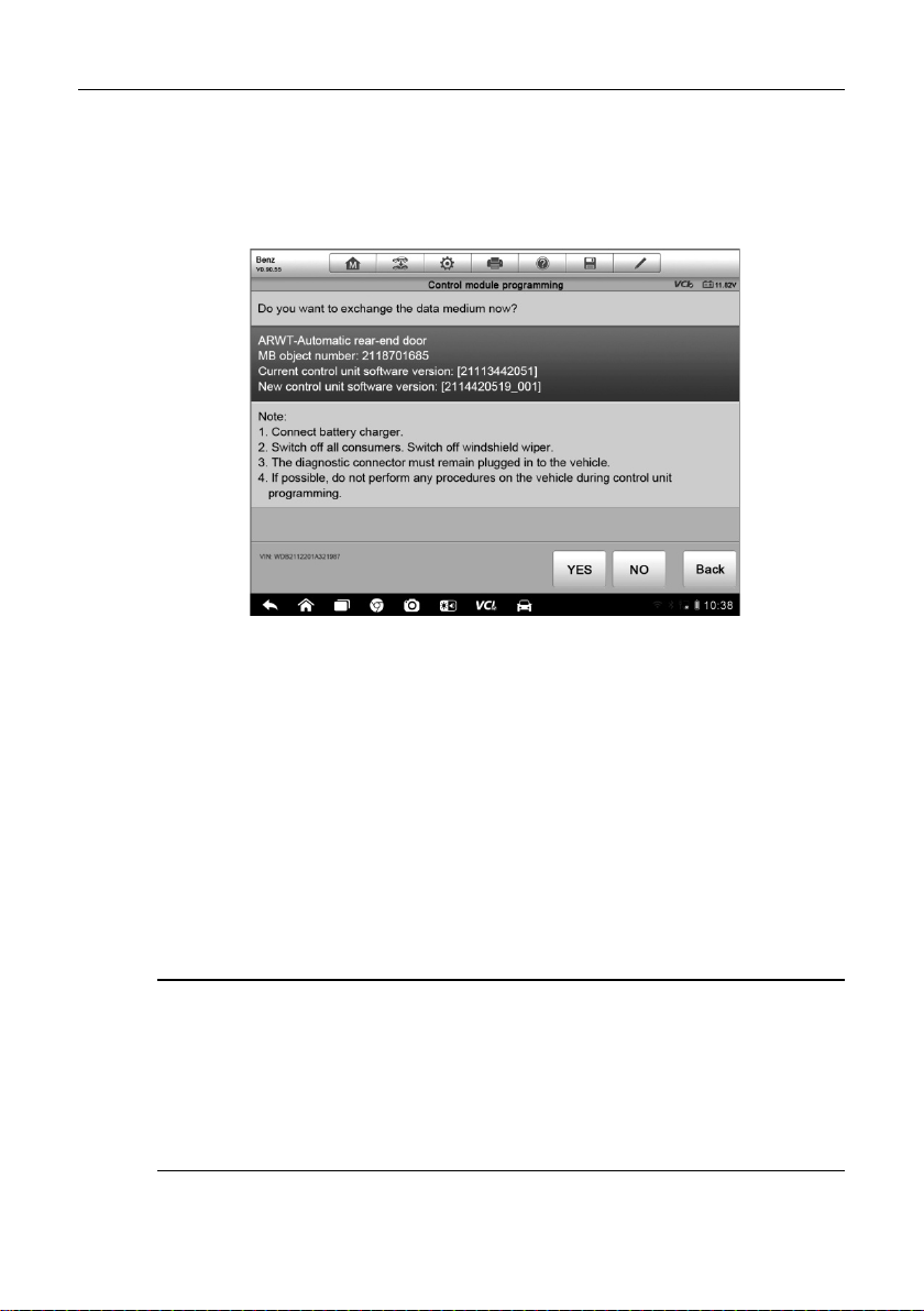
Diagnostics Operations Programming and Coding
Reprogramming Operation
Typical reprogramming operations require you to input and validate VIN
number first. T ap the input box and enter the correct number, the programming
interface then displays.
Figure 4-17 Sample Reprogramming Operation Scree n
The main section of the reprogramming interface provides you certain
hardware version, and current s oftware versions’ inf ormation, as well as the
information of the newest software vers ions to be programmed to t he control
units.
Throughout the programming procedure, a series of on-screen operational
instructions will display to guide you through.
Carefully read the on-screen informat ion and follo w the instruction to e xecute
the programming procedure.
Re-flash Errors
IMPORATANT: When reprogramming onboard, al ways make s ure the veh icle
battery is fully charged and in good working cond ition. During re programming
there is a risk of having the operat ion failure if voltage f alls below the proper
operation voltage. Sometimes a failed operation can be recovered, but there is
a chance that failed reprogramming could ruin the control module. We
recommend connecting an external batter y charger to the vehicle to ensure a
successful operation.
56
Page 64

Diagnostics Operations Generic OBD II Operations
Occasionally a flash update procedure ma y not complete properly. Common
causes of flash errors include poor cable connections between the display
tablet, VCI, and vehicle, turni ng off the vehicle ignition switch before t he flash
procedure is complete, or low vehicle battery voltage.
If the process crashes, recheck all the cable connections to assure good
communications and reinitialize the flash procedure. The programming
procedure will automatically repeat if the previous operation does not
succeed.
4.9 Generic OBD II Operations
A fa st -access option for OBD II/EOBD vehicle diagnosis is available on the
Vehicle Menu screen (Figure 4-2). This option presents a q uick way to check
for DTCs, isolate the cause of an illuminated malfunction indicator lamp (MIL),
check monitor status prior to emi ssio ns c ert i fic ation t est i ng, ver if y repa irs , and
perform a number of other services that are emissions-related. The OBD
direct access option is also us ed for testing OBD II/EOBD compliant vehicles
that are not included in the Diagnosti c s database.
Functions of the diagnostics toolbar buttons at the top the screen are the
same as those available for specific vehicle diagnostics. See Table 4-2
Diagnostics Toolbar Buttons on page 33 for details.
4.9.1 General Procedure
To access the O BD II/EOBD diagnostics functions
1. Tap the Diagnostics application button from the MaxiSys Job
Menu. The Vehicle Menu displays.
2. Tap the EOBD button. There are two options to establish
communication with the vehicle.
Auto Scan – When this option is s elected the diagnostic tool
attempts to establish communication using each protocol in
order to determine which one the vehic l e is broadcasting on.
Protocol – When this option is selected the screen opens a
submenu of various protocols. A communication protocol is a
standardized way of data communication between an ECM
and a diagnostic tool. Global OBD may use several different
communication protocols.
57
Page 65
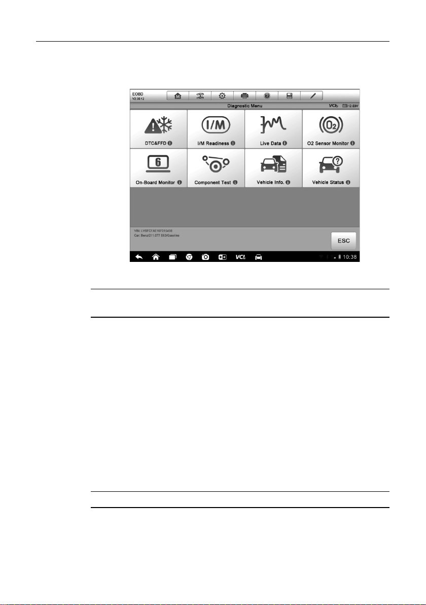
Diagnostics Operations Generic OBD II Operations
3. Select a specific protocol if the Protocol option is selected. Wait for
the OBD II Diagnostic Menu to appear.
Figure 4-18 Sample OBD II Diagnostic Menu
A
NOTE: The
iE A button dis played beside the function name is tappable,
○
tapping which opens a bubble with additional function information.
4. Select a function option to continue.
DTC & FFD
I/M Readiness
Live Data
O2 Sensor Monitor
On-Board Monitor
Component Test
Vehicle Information
Vehicle Status
NOTE: Some functions are supported only on certain vehicle makes.
58
Page 66

Diagnostics Operations Generic OBD II Operations
4.9.2 Function Descriptions
This section describes the various functions of each diagnostic optio n:
DTC & FFD
When this function is selected , the scr een displa ys a list of Stor ed Codes and
Pending Codes. When the Freeze Frame dat a of certain DTCs are available
for viewing, a snowflake button will dis play on the right side of the DTC item.
The Erase Codes function can be applied b y tapping the functional button at
the lower bottom of the screen.
Figure 4-19 Sample DTC & FFD Screen
Stored Codes
Stored codes are the current emission relat ed DTC s from the ECM of the
vehicle. OBD I I/EOBD Codes have a priority accor ding to their emission
severity, with higher priority codes overwriting lower prior ity codes. The
priority of the code determines the ill umination of the MIL and the codes
erase procedure. Manufacturers rank codes differently, so expect to see
differences between makes.
Pending Codes
These are codes whose setting conditions were met during the last dr ive
cycle, but need to be met on two or more consecutive drive cycles before
the DTC actually sets. The intended use of this service is to assist the
service technician after a vehicle repair and after clearing diagnostic
information, by reporting test results after a single driving cycle.
59
Page 67

Diagnostics Operations Generic OBD II Operations
a) I f a test failed dur ing the drivi ng cycle, the D TC associ ated with that
test is reported. If the pending fault does not occur again within 40 to
80 warm-up cycles, the fault is automatically cleared from memory.
b) Test results reported by this service do not necessarily indicate a
faulty component or system. If test results indicate another failure
after additional driving, then a DTC is set to indicate a faulty
component or system, and the MIL is illuminated.
Freeze Frame
In most cases the stored frame is the last DTC that occurred. Certain
DTCs, those that have a greater impact on vehicle emission, have a
higher priority. In these cases, the highest priority DTC is the one for
which the freeze frame records ar e retained. Freez e frame data inclu des
a “snapshot” of critical parameter values at the time the DTC is set.
Erase Codes
This option is used to clear all emission related diagnostic data such as,
DTCs, freeze frame data and manufacturer s pecific enhanced data from
the vehicle’s ECM, and resets the I/M Readiness Monitor Status for all
vehicle monitors to Not Ready or Not C om plete status.
A confirmation screen displays when the clear codes option is select e d to
prevent accidental loss of data. Select Yes on the confirmation s creen to
continue, or No to exit.
I/M Readiness
This function is used to check the readin ess of the monitori ng system. It is an
excellent function to use prior to havi ng a vehicle insp ected for complia nce to
a state emissions program. Select ing I/M Readiness opens a submenu with
two choices:
Since DTCs Cleared – displays the status of monitors since the last time
the DTCs are erased.
This Driving Cycle – displays the status of monitors since the beginning
of the current drive cycle.
60
Page 68

Diagnostics Operations Generic OBD II Operations
Live Data
This function displays the real time PID data from ECU. Displayed data
includes analog inputs and outputs, digital inputs and outputs, and system
status information broadcast on the vehicle data stream.
Live data can be displayed in various m odes, see 4.6.4 Live Data o n page 43
for detailed information.
O2 Sensor Monitor
This option allows retrieval a nd viewing of O2 sensor monitor tes t results for
the most recently performed tests from the vehicle’s on-board computer.
The O2 Sensor Monitor test function is not supported by vehicles which
communicate using a controller are a network (CAN). For O2 Sensor Mo nitor
tests results of CAN-equipped vehicles, refer to On-Board Moni tor.
On-Board Monitor
This option allows you to view the results of On-Board Monitor tests. The tests
are useful after servicing or af ter erasing a vehicle’s control module memory.
Component Test
This service enables bi-directiona l control of the ECM so that the diagnostic
tool is able to transmit control commands to operate the vehicle systems. This
function is useful in determining how well the ECM responds to a command.
Vehicle Information
The option displays the vehicle identification number (VIN), the calibration
identification, and the calibration verification number (CVN), and other
information of the test vehicle.
Vehicle Status
This item is used to check the current condition of the vehicle, including
communication protocols of O BD II modules, retrieved code s amount, status
of the Malfunction Indicator L ight (MIL), and other a dditional information may
be displayed.
61
Page 69

Diagnostics Operations Exiting Diagnostics
4.10 Exiting Diagnostics
The Diagnostics application remains open as long as there is an active
communication with the vehicle. You must exit the diagnostics operation
interface to stop all communications with the vehicle before closing the
Diagnostics application.
NOTE: Damage to the vehicle electronic control module (ECM) may occur if
communication is disrupted. Make sure the all connections, such as data
cable, USB cable, and wireless or wired network, are properly connected at all
times during testing. Exit all tests before disconnecting the test cable or
powering down the tool.
To exit the Diagnostics application
1. From an active diag nostic screen, tap the Back or ESC functional
button to exit a diagnostic session step-by-step; Or
2. Tap the Vehicle Sw ap button on the diagno stics toolbar to return to
the Vehicle Menu screen.
3. From the vehicle menu screen, tap the Home button on the top
toolbar; or tap the Back button on the navigation bar at the bottom of
the screen. Or
4. Tap the Home button on the diagnostics toolbar to exit the
application directly to the MaxiSys Job Menu.
Now, the Diagnostics application is no longer communicat ing with the vehicle
and it is safe to open other MaxiSys applicat ions, or exit the MaxiSys Elite
Diagnostic System and return to the Android System’s Home screen.
62
Page 70

Chapter 5 Data Manager Operations
The Data Manager application is us ed to store, print , and review the saved files. Most
operations are controlled through the toolbar.
Selecting the Data Manager applicat i on opens the file system menu. Different file types
are sorted separately under different options, there are six types of information files t o
be viewed or played back.
Figure 5-1 Sample Data Manager Main Screen
5.1 Operations
Data Manager Operations are based on toolbar controls, details are explained
in the following sections.
5.1.1 Image Files
The Image section is a JPG database containing all captured screenshot
images.
63
Page 71

Data Manager Operations Operations
Touching this button opens a window
deletes the selected
Figure 5-2 Sample Image Database Screen
1. Toolbar Buttons – used to edit, print and delete the image files. See
Table 5-1 Toolbar Buttons in JPG Database on page 64 for detailed
information.
2. Main Section – displays the stored im ages.
Table 5-1 Toolbar Buttons in JPG Database
Name Button Description
Back
Enter Edit
Cancel
Search
Info
Print
Delete
Returns to the previous screen.
Touching th is button shows the editing toolbar
to print, delete or view image information.
Touching this button close the editing toolbar
or cancels file search.
Quickly locates the image file b y entering the
vehicle name, test path, file name or file info.
displaying the detail information of the image.
Touching this button prints the selected image.
Touching this button
image.
64
Page 72

Data Manager Operations Operations
To edit image information
1. Select Data Manager application from the MaxiSys Job Menu.
2. Select Image to acces s the JPG database.
3. Select an image to display it in full screen.
4. Tapping the screen once displays the editing toolbar.
5. Tap the Info button to open a window displaying the image
information.
6. Tap the Edit button on the top right corner of the window. The
editing screen displays.
7. Edit the image informati on by entering the new file name, and file
information.
8. Tap Done to save the information and exit, or tap Cancel to exit
without saving.
To delete selected images
1. Select Data Manager application from the MaxiSys Job M enu.
2. Select Image to access the JPG database.
3. Tap the Enter Edit button to display the editing toolbar.
4. Select the images that need to be deleted by tappi ng the thumbnail
images, the selected thumbnail displays a tick icon at the bottom
right corner.
5. Tap the Delete button, and then Delete Select ed, now the selected
images are deleted.
5.1.2 PDF Files
The PDF section stores and displays all PDF files of saved data. After entering
the PDF database, select a PDF file to view the stored information.
This section uses the standard Adob e Reader application for file vie wing and
editing, please refer to the associated Adobe Reader manual for more detailed
instructions.
65
Page 73

Data Manager Operations Operations
5.1.3 Review Data
The Review Data section allows you to pla yback the recorded d ata frames of
live data streams.
On the Review Data main screen, selec t a record file to playback.
Figure 5-3 Sample Data Playback Screen
1. Drop-down Toolbar – tap the butt on at the top center of the screen to
open the Drop-down Toolbar
2. Main Section – displays the recorded data frames
3. Navigation Toolbar – allows you to manipulate data playback
Use the Navigation Toolbar buttons to playback the record data from frame to
frame.
Tap Back t o exit data playback.
5.1.4 Apps Manager
This section allows you to manage the firmware applications installed on the
MaxiSys Elite Diagnostic System. Selecting this section opens a managing
screen, on which you can check all the available vehicle diagnostic
applications.
66
Page 74

Data Manager Operations Operations
Select the vehicle firmware you want to delete by tapping on the car brand
icon, the selected item will display a blue tick at the upper right corner. Tap the
Delete button on the top bar to delete the firmware from the system database.
5.1.5 Data Logging
The Data Logging section allo ws you to laun ch Support p latform di rectly to v iew all
records of every s ent or uns ent (saved) data loggin g on the diagnostic s ystem. For
more details, please refer to 12.5 Data Logging on Page 104.
67
Page 75

Chapter 6 MaxiFix Operations
The MaxiFix application launches the on-line troubleshoot er database, which not only
provides you virtually all common diagnostic trouble code (DTC) database for most
vehicles, but also serves as a forum all o wing you to net work wit h other Ma xiS ys users,
and gives you access to a vast database of repair and diagnostic tips along with proven
filed fixes.
While the MaxiFix provides the abundant troubleshooter information available, the
database keeps growing with daily troubleshooting resources by recording the reported
solution cases, and the advisory reports of the MaxiSys users from all over the world.
Information in the MaxiFix database is organized into a series of diagnostic tips that are
designed to quickly lead you to the root cause of a particular problem on the test vehicle,
which will help you quickly find solution for various diagnostic problems.
6.1 Navigation
You n eed to register the device to your online account before launching the
MaxiFix platform, see 12.1 Product R egistration on page 99 for details.
Figure 6-1 Sample MaxiFix Home Page
68
Page 76

MaxiFix Operations Navigation
The MaxiFix interface has 3 m ain areas:
1. Header Bar – located across the top of the page, is used to select
vehicles and perform keyword searches.
2. Navigation Bar – located along the left-hand side of the page i s used t o
access the main features of MaxiFix.
3. Main Screen – The center portion of the page presents content based
on the vehicle attributes and keywords selected. The main screen als o
has tabs that allow you to switch between functions. Which tabs are
available depend on which function is selected on the Navigation Bar.
Header Bar
The Header Bar, which runs across the top of the page, features:
A Select Vehicle button to open the vehicle identification window, and
vehicle information bar displaying the active vehicle information, for
example “2013 > Honda > Crosstour > EX”.
A search field used for entering keywords, codes, or symptoms.
Select Vehicle Button
The “Select Vehicle” button, located on the Header Bar, is used to identify
which vehicle you want to reference on MaxiFix. Vehicle attributes are
selected from a sequence of option lists. Make a selection to advance through
the lists. This data is used to filter searches so that only information that
applies to the identified vehicle i s shown.
To select a veh icle
1. Tap the Select Vehicle button on the Header Bar at t he top of the
page.
2. Select the year of the vehicle from the list that displays.
3. Select the make of the vehicle from the list that displays.
4. Select the model of the vehicle f rom the list that displays.
5. Select the submodel of the vehicle from the l ist that displays.
6. Select the engine of the vehicle from the list that displays.
7. After making a full s election by choosing all vehicle attributes, the
screen refreshes and the selected vehicle is now shown on the
Header Bar.
69
Page 77

MaxiFix Operations Navigation
6.1.1 Terminology
MaxiFix Tip
MaxiFix Tips are concise and complete descriptions of a real fix for a particular
vehicle repair issue. A MaxiFix Tip is a combination of proven fixes and vehicle
specific data we have collected and analyzed into an all-in-one information
source to help you fix vehicle problems quickly and easily.
On MaxiFix you can search for Tips or enter your own Tip to help other
community members resolve vehicle issues.
MaxiFix Tips consist of 3 types of Tips:
1. Autel Certified Tips – these tips have gone throu gh rigorous revie w by
experts.
2. Real Fix Tips – these tips are gathered from actual shop repair orders
and are presented in an easy to understand Complaint, Cause,
Correction format.
3. MaxiFix Community Tips – thes e are Tips that have been created by
the MaxiFix Community Members.
To search for a Maxi Fix Tip
1. Tap the Select Vehicle button on the Header Bar at the top of the
page to select a specific vehicle.
2. Enter a search term into the input f ield of the search bar which is
located on the Main Screen.
3. The search results are displayed in a list. Find a subject that
interests you; tap it to view the full details.
Fixed It!
The “Fixed It !” designation that appears in the head line of a Tip indicates that
the Tip in question has actually helped at least one technician in the
community repair a vehicle. Anytime you read a Tip you are given the
opportunity to add to the Fixed It! count if the Tip helped you repair a problem.
Each time someone taps “Fixed It!” in the tip, one is added to the total number
of Fixed It! for the tip. The Fix ed It! count lets you easily see what tips are
actually helping to resolve vehicle issues.
70
Page 78

MaxiFix Operations Operations
6.2 Operations
The Navigation Bar is on the left side of the screen. Buttons on the Navigat ion
Bar launch the main sections of MaxiFix. Availabl e Navigation Bar selections
include:
Home – shows the recently viewed questions and fixes, the Leaderboard,
along with a link to your profile inform ation.
My MaxiFix – shows all your posts including Q uestions and Tips in the
community, and allows you to ask a question and enter a tip.
Search Fix – allows you to search for information from all available
resources on MaxiFix, including: Open Que stions, Tips, and Real Fixes,
and displays search results.
All Questions – displays the latest questions and fixes.
My Messages – shows a list of message notifications which is relevant
to your activities in the Question section.
Support – opens the FAQ page, or a message box for contacting
Customer Service by email.
6.2.1 Home
Home, is the first option on the Navigation Bar along the left side of the screen,
opens the home page on MaxiFix. There are three functions available.
Leaderboard – shows the top ranked MaxiFix community members.
My Recently Viewed – shows a list with links to the Questions, Tips, and
Real Fixes that you recently visited.
Profile Information – quick link to your profile information page.
Leaderboard
The Leaderboard shows the top ranked MaxiFix community members.
Community members are awarded points for answering que stions, and those
who gather the most points show on the MaxiFix Leaderboard. The more
points you have the better the chance you have to get on the Leaderboard.
71
Page 79

MaxiFix Operations Operations
To show on the Leaderboard the community members must answer questions
to get points.
Points System
3 points are awarded when you close a quest ion.
2 points are awarded if your closed question is picked as "Fixed it!" by no
less than 20 community members.
4 points are awarded if your answer is rate d as the “Best Answer”.
1 point is awarded if your answer is rated as the " Best Answer" for a
closed question which is picked as "Fixed it!" by no less than 20
community members.
1 point is awarded to each of the first three r es pondents.
Edit Profile Information
You can v iew or edit your personal profile by clicking on your account ID or
portrait where applicable, and visit other community members’ profile by
clicking their portrait. Information t hat include in your profile determines how
you are presented to the communit y, and what type of information will be sent
to you from the community.
There are four tabs in your profile screen:
1. User Profile – allows you to manage your Autel account profile
information including: your Autel ID, personal information, M axiF i x point s,
level, phone number, and register time.
2. Vehicle Selection – used to set up a list of preferred vehicles. The
preferred list allows you to li mit the choices that display on the “Select
Vehicle” list to specific years, and makes. Click “Set Year” or “Set Make”
to set your preferred models.
3. Expert Subscriptions – allo ws you to share your knowledge by alerting
you when there is a question related to an indicated area of your
expertise.
Select the “Expert Subscriptions” tab on t he main page to open a menu for
identifying your areas of exper tise. Your expert subscription can be limited to
specific makes, models, years, and engine. You will receive an email
whenever a question posted is related to your area(s).
Click the link in the email which directs to the question. This lets you quickly
respond to questions and build Leaderboard points.
72
Page 80

MaxiFix Operations Operations
4. Communication – lets you manage your communication preferences.
Here you can choose which email notifications you would like to recei ve
from MaxiFix.
6.2.2 My MaxiFix
My MaxiFix, the second option on the Navigat ion B ar a lon g t he lef t s ide of the
screen, opens your personal MaxiFix page. To access the features on My
MaxiFix page you can either select from the tabs or use t he links on the t op of
the page:.
Questions – opens a list with links to the opened questions that you
have posted to the community
Stuff – opens a list with links to the closed questions and tips that you
have contributed to the community.
Follow – opens a list with links to Tips and discussions that you are
actively participating in.
Library – provides PID G raphs and/or Waveforms associated with the
Tip and the vehicle you have selected. This is a comprehensive
collection of test results gathered t hrough ac tual o n-vehic le tes ts, so you
know exactly what to look for. Data graphs and scope waveforms provide
a point of reference to help you verify faulty parts.
Ask the Experts – allows you to post a questi on to the community.
Enter a Tip – allows you to shar e your personal repair experience with
the community
Tap My MaxiFix on the Navigation Bar al ong the left s ide of the scree n,
to display all questions and tips that you have contributed to the
community.
To ask a question on MaxiFix
1. If not already done, tap Select Vehicle on the Header Bar and
enter the identifying attributes of the v ehicle you would like t o ask a
question about.
2. Tap My MaxiFix on the Navigation Bar along the left-side of the
screen to open the My MaxiFix page.
3. On the My MaxiFix page find Ask the Experts; tap this link to open
the Question Page.
73
Page 81

MaxiFix Operations Operations
The Question page has 4 sections:
Subject – this is where you enter a brief subject for the
question.
Symptoms – this is where you describe how the vehicle is
behaving.
Diagnostics Steps Performed/Parts Replaced – include any
previous diagnostic tests that you performed, including the
results of the tests. Also list any parts that were replaced during
previous diagnostic work.
Your Question – ask a clear and concise question that you
want to ask the community. Be sure to be descriptive and
concise when asking your question.
4. Tap the Cancel button at the right-side bottom of the page to cancel
your question and return to the My MaxiFix page. Or,
5. Tap the Submit button at the right -side bottom of the page to ask
your question of the community.
“Best Answer” Rating
Rating answers is one way to give back to the MaxiFix community. The
member that originally asked the qu esti on ge t s t o select a “Bes t Answer” from
all of the responses. The community member that provided the Best Answer to
a question is recognized for their contribution.
About Best Answer:
Only one answer can be rated “Best Answer”.
Only the MaxiFix community member who asked the qu estion can rate
the answers.
Close a Question
Questions that you post to the communit y need to be cl osed once the veh icle
repair issue has been resolved. You are encouraged to document the fix, and
an important part doing so is prov iding information on wha t actually fixed the
vehicle so that other MaxiFix com munity me mbers can use the inform ation as
well.
To close a que stion you need to pick the “Best Answer” from the answers at
the “Question” page first. It is strongly recommended to share your fix
74
Page 82

MaxiFix Operations Operations
experience before closing a question. Your question will be converted to a
MaxiFix Community Tip after closing.
Create a Tip
If you have a new fix to a specific v ehicle problem please share! Create a
MaxiFix community Tip to share your expertise with ot her technicians in the
MaxiFix community.
A MaxiFix community Tip is a short yet complete description of t he repair for a
particular vehicle problem.
To create a new MaxiFix Tip
1. Select My MaxiFix from the Navigation Bar.
2. Tap Select Vehicle from the Header Bar and enter the identif ying
attributes of the vehicle you are writ i ng the Tip about.
3. On the My MaxiFix page f ind Enter a Tip; tap this link to open the
Tip Page.
4. Enter the Tip Title in the Title field.
5. Compose your Tip in the Content field. Includes as much information
as possible, while keeping th e information concis e and to the point.
A Tip should provide accurate information that is easy to read,
understand, and follow.
6. Tap the Cancel button at the right-side bottom of the page to cancel
your tip and return to the My MaxiFix page. Or,
7. Tap the Submit button at the right-side bottom of the page to
contribute your tip to the communit y.
6.2.3 Search Fix
Search Fix, the third option on the Navi gation Bar along the left side of the
screen, presents search results for the active vehicle. Search results are listed
in various categories:
All – inclu des all search results, including related Quest ions, Tips, and
Real Fixes to your search.
Questions – presents a list of open Question discussed in the
community that may be pertinent to your search.
75
Page 83

MaxiFix Operations Operations
Tips – presents a list of Tips that directly correlate to your search criteria.
Select a Tip from the list to open and review the complete Tip.
Real Fixes – presents a list of Tips that have been gather ed fr om actual
shop repair orders and are presented in an easy to understand
Complaint, Cause, Correction f or mat.
6.2.4 All Questions
All Questions, the fourth option on the Navig ation Bar along the left side of the
screen, presents the latest updated quest ions and tips in MaxiFix community.
There are two tabs available to look u p:
Latest Questions – displays a list of latest posted questions. Select a
question from the list to join the discussion or submit an answer to
contribute your expertise.
Latest Tips – displays a list of latest posted tips. Select a tip from the list
to find out the repair advice and tip contri but e d by a com mu nit y mem ber.
If you find the tip is helpful to solv e your repair problem, you can give the
tip one “Fixed It!" point by tapping it.
You c an configure your main screen to displ ay questions only related to the
vehicle models you are interested, b y clicking the Filter button on the main
page of All Questions, and select the desired vehicle models. This filter can be
canceled anytime by clicking the Remove All Filters button, and the default
setting will be recovered to display questions about all vehicle models .
6.2.5 My Messages
My Messages, the fifth option on the Navigati on Bar along the left side of t he
screen, shows a list of message notifications which is relevant to your
activities in the Question section.
A notification icon will appear on the top-right corner of the “My Messages” tag
when you launch the MaxiFix application when there is any new or unread
message in the Question section. The number on the notification icon
indicates the total number of the new and unread messages. The disp layed
number will be reduced correspondingly after viewing. The message
notification will appear in the fol lowing two cases:
1. Y our question or answer is replied by other MaxiFix community members.
76
Page 84

MaxiFix Operations Operations
2. Your answer is rated as the “Best Answer” by the MaxiFix community
member who asked the question.
Tap My Message, select the message notification you want to read in the list.
If your answer is rated as the “Best Answer”, the prompt “Best Answer + 4” will
be displayed permanently.
Tap Clear to delete all message notifications in the list.
6.2.6 Support
Support, the last option on the Navigation Bar along the left side of the screen,
opens a page that provides 2 ways to gai n support from MaxiFix:
1. A message form to contact the administrator of MaxiFix.
2. A Frequently Asked Questions (FAQ) link that answers the most frequent
questions we hear from MaxiFix comm unity members.
If you wish to contact the administrator of this site please use the contact form.
Select “Support” from the Navigation Bar to open the comment window. To
allow the administrator to respond to your question or issue, the following
information should be provided:
Your name
A contact email address
A contact phone number
77
Page 85

Chapter 7 Settings Operations
Selecting Settings application opens a s etup interf ace, on which you can adjust default
setting and view information about the MaxiSys system. There are eight options
available for the MaxiSys system settings:
Unit
Language
Printing Setting
Wired Network
Notification Center
Multitask
About
System Settings
7.1 Operations
This section describes the operation procedures for the settings.
7.1.1 Unit
This option allows you to adjust the measurement unit for the diagnostic
system.
To adjust the unit setting
1. Tap the Settings application on the MaxiSys Job Menu.
2. Tap the Unit option on the left column.
3. Select the required meas urement unit, Metr ic or English. A tick icon
will display to the right of the select ed unit.
4. Tap the Home button on the top left corner to return to the MaxiSys
Job Menu. Or select another setting option for the system setup.
78
Page 86

Settings Operations Operations
7.1.2 Language
This option allows you to adjust t he display language for the MaxiSys Elite
system.
To adjust the language setting
1. Tap the Settings application on the MaxiSys Job Menu.
2. Tap the Language option on the left column.
3. Select the required language. A tick icon will display to the right of
the selected language.
4. Tap the Home button on the top left corner to return to the MaxiSys
Job Menu. Or select another setting option for the system setup.
7.1.3 Printing Setting
This option allows you to print any data or information anywhere and anytime
either via PC network or Wi-Fi. For more information ab out printing, see 3.3.1
Printing Operation on page 17.
To setup the printer connection
1. Tap the Settings application on the MaxiSys Job Menu.
2. Tap the Printing Setting option on the left column.
3. Tap Print via Network to activate the printing function, which
enables the device to send files to t he printer through the PC via
Wi-Fi or Ethernet connection.
4. Tap the Home button on the top left corner to return to the MaxiSys
Job Menu. Or select another setting option for the system setup.
7.1.4 Wired Network
This option allows you to ena ble or disable t he wired net work connectivit y, as
well as to perform Ethernet configuration.
To operate Ethernet configuration
1. Tap the Settings application on the MaxiSys Job Menu.
79
Page 87

Settings Operations Operations
2. Tap the Wired Network option on the left column.
3. Tap the ON/OFF button to enable the Wired Net work connection. If
the connectivity is enabled t he button turns blue, or if disabled the
button turns gray.
A
4. Tap the
>E A button to the right of the Ethernet Configuration option, a
○
setup window displays.
5. Select a conne ction type:
DHCP – obtains the LAN IP address automatically
Static IP – allows manual input of IP address
6. If Static IP is selected, you need to enter the IP values manually.
NOTE: If you are not sure about the speci fic IP address values, please
contact your network administrator.
7. Tap Save to sav e the Ethernet configuration s etting; or tap Cancel
to exit without saving.
8. Tap the Home button on the top left corner to return to t he MaxiSys
Job Menu. Or select another setting option for the system setup.
7.1.5 Notification Center
This option allows you to turn the Notification Center function on or off. The
Notification Center function configures the MaxiSys tablet to receive r egular
on-line messages from the server for system update notifications or other
service information via the Internet. It is highly recommended to keep this
function on all the time, so you won’t miss out any new update for MaxiSys or
event from Autel. Internet access is required for r eceiving on-line messages.
To enable the Push Message function
1. Tap the Settings application on the MaxiSys Job Menu.
2. Tap the Notification Center option on the left column.
3. Tap the ON/OFF button to enable or disable the Not ification Center
function. If the function is enabled the button turns blue, or if
disabled the button turns gray.
80
Page 88

Settings Operations Operations
4. Tap the Home button on the top left corner to return to the MaxiSys
Job Menu. Or select another setting option for the system setup.
When the Notification Center function is turned on, and new messages are
received by the MaxiSys device, a notification message displays on the
MaxiSys Job Menu. Press on the message bar and drag it down, and the
received messages are shown in th e list, s lide the list up or do wn to view all if
the message list covers more than on e screen.
Tapping a specific message launches the corresponding application. For
example, if you tap on an Update notification message, the Update application
will be launched.
7.1.6 Multitask
The Multitask option allows you to turn Multitask function on or off. The
Multitask feature enables you to browse and navigate more freely among
different applications on the MaxiSys system. By simply tapping the Multi Task
button, the Multi Task menu displays all bookmarks of the active applications
allowing you to switch from one app to a nother in just 1 second.
To enable the Multitask function
1. Tap the Settings appl ication on the MaxiSys Job Menu.
2. Tap the Multitask option on the left column.
3. Tap the ON/OFF button to enable or disable the Multitask function. If
4. Tap the Home button on the top left corner to return t o the MaxiSys
7.1.7 About
The About option provides information of the MaxiSys Elite diagnostic device
regarding the product name, version, hardware, and serial number, etc.
the function is enabled the button turns blue, or if disabled the button
turns gray.
Job Menu. Or select another setting option for the system setup.
81
Page 89

Settings Operations Operations
To check the MaxiSys product information in About
1. Tap the Settings application on the MaxiSys Job Menu.
2. Tap the About option on the left column. The prod uct information
screen displays on the right.
3. Tap the Home button on the top left corner to r eturn to the MaxiSys
Job Menu, or select another setting option for the system setup,
after viewing.
7.1.8 System Settings
This option provides you a direct access to the Android background system
setting interface, on which you can adjust various system settings for the
Android system platform, regarding wireless and networks settings, various
device settings such as sound and display, as well as system security settings,
and check the associated information abo ut the Androi d system, etc. Refer to
Android documentation for additi onal information.
82
Page 90

this button to create a new customer
Chapter 8 Shop Manager Operations
The Shop Manager application helps you to manage the workshop information,
customer information rec ords, and keep test vehicle history records, whic h can be a
great assist in dealing with dai ly workshop business and improves customer service.
There are three main functions available:
Vehicle History
Workshop Information
Customer Manager
The operations of these functions of the Shop Manager application are mainly
manipulated by the toolbar buttons , which are listed and described in the table below:
Table 8-1 Top Toolbar Buttons in Shop Manager
Name Button Description
Back
Diagnostics
Enter Edit
Delete
Search
Cancel
Edit
Add Account
Returns to the previous screen.
Touching this button directs you to the vehicle’s
Diagnostics screen to activate a direct test session.
Touching this button shows the editing toolbar to
print or delete the selected file.
Touching this button deletes the selected vehicle
record item from the list.
Quickly locates the vehicle record b y entering the
vehicle name or test path.
Touching this button to cancel edit or file search.
Touching this button allows you to edit information
for the displayed file.
Touching
account file.
83
Page 91

Shop Manager Operations Vehicle History
Touching this button opens a note form, which
Vehicle History
records.
Name Button Description
History Notes
Vehicle
History
Done
8.1 Vehicle History
This function stores records of test vehicle history, including vehicle
information and the retrieved DTCs from previous diagnostic sessions, and
displays all information in an easy-to-check table lis t, on which you can view
summarized details and manually input other information about the test
vehicle and diagnostic loggi ngs, etc. The Vehicle History also provid es direct
access to the previously tested vehicl e and allows you to restart a diagnostic
session without the need to do vehicl e identification again.
allows you to create audio record, attach pictur e or
video, or edit text notes, etc.
Touching this button opens the
screen which displays the correlated test vehicle
Saves the file when complete editin g.
Figure 8-1 Sample Vehicle History Screen
1. Top Toolbar Buttons – navigates and makes various controls of the
application.
2. Main Section – displays all the vehic l e history records information.
84
Page 92

Shop Manager Operations Vehicle History
To activate a test session for the recorded vehicle
1. Tap the Shop Manager application on the MaxiSys Job Menu.
2. Select Vehicle History
3. Tap the Diagnostics button at the bottom of the thumbnail of a
vehicle record item. Or,
4. Select a vehicle record item by tapping the thumbnail.
5. A Historical Test record sheet displays, check the recorded
information of the recorded test vehicle, and tap the Diagnostics
button on the upper right corner.
6. The vehicle’s Diagnostics screen displays, now a new diagnostic
session is activated, see 4.6 Diagnosis on page 37 for detailed
instructions on vehicle diagno s tic operations.
8.1.1 Historical Test Record
The Historical Test record sheet of the tested vehicle is a detailed data form,
which includes all general information of the vehicle such as vehicle year,
make and model, etc., and the diagnostic trouble codes retrieved from the
previous test sessions, as well as other service details which can be added
manually by the technician himself.
Figure 8-2 Sample Historical Test Record Sheet
85
Page 93

Shop Manager Operations Workshop Information
To edit the Historical Test record sheet
1. Tap the Shop Manager application on the MaxiSys Job Menu.
2. Select Vehicle History.
3. Select the specif ic vehicle history record thumbnail from the main
section. The Historical Test record sheet displays.
4. Tap the Edit button to start editing.
5. Tap on each item to input the corresponding information or add
attaching files or images.
NOTE: The vehicle VIN number, or license and the customer information
account are correlated by default. Adding one of the information will
automatically associate the other it em in the record sheet, provided that
the later one exists.
6. Tap Add to Customer to correlate the Historical Test record sheet to
an existing customer account, or add a ne w associating account to
be correlated with the test vehicle record. See 8.3 Customer
Manager on page 87 for more informat ion.
7. Tap Done to save the updated r ecord sheet, or tap Cancel to exit
without saving.
8.2 Workshop Information
The Workshop Information form allows you to edit, input and save the detailed
workshop information, such a s shop n ame, addr ess , pho n e numb er an d other
remarks, which, when printing vehicl e d iag no st ic repor ts an d ot her assoc i at ed
test file, will appear as the header of t he printed documents.
86
Page 94

Shop Manager Operations Customer Manager
Figure 8-3 Sample Workshop Information Sheet
To edit the Workshop Information sheet
1. Tap the Shop Manager application on the MaxiSys Job Menu.
2. Select Workshop Information.
3. Tap the Edit button on the top toolbar.
4. Tap on each field to input the appropriate information.
5. Tap Done to save the updated works hop information sheet, or tap
Cancel to exit without saving.
8.3 Customer Manager
The Customer Manager function allows you to create and edit customer
accounts. It helps you to save and or ganize all customer information accounts
that are correlated with the associate d test vehicle histor y records, which is a
great support for the arrangement of dai ly workshop business.
To create a customer account
1. Tap the Shop Manager application on the MaxiSys Job Menu.
2. Select Customer M anager.
3. Tap the Add Account button. An empty information form displays,
tap each field to input the appropriate information.
NOTE: The items that must be filled are indicated as required fields.
87
Page 95

Shop Manager Operations Customer Manager
4. Tap the A□+E A photo frame beside the Name chart to add a photo. A
sub menu displays, select Take Photo to take a new photo for the
account, or select Choose Photo to choose from the existing files.
5. Some customers may have more than one vehicle for service; you
can always add new vehicle information to the account to be
correlated. Tap Add New Vehicle Information, and then fill in the
vehicle information. Tap the
A
xE A button to cancel adding.
○
6. Tap Done to save the account, or tap Cancel to exit without saving.
To edit a customer account
1. Tap the Shop Manager application on the MaxiSys Job Menu.
2. Select Customer M anager.
3. Select a customer account by tapping the corresponding name card.
A Customer Information sheet displays.
4. Tap the Edit button on the top toolbar to start editing.
5. Tap on the input field where needs to be altered or supplemented,
and enter updated information.
6. Tap Done to save the updated information, or tap Cancel to exit
without saving.
To delete a customer account
1. Tap the Shop Manager application on the MaxiSys Job Menu.
2. Select Customer M anager.
3. Select a customer account by tapping the corresponding name card.
A Customer Information sheet displays.
4. Tap the Edit button on the top toolbar to start editing.
5. Tap the Delete Customer Information button. A confirmation
message displays.
6. Tap OK to confirm the command, and the account is delet ed. Tap
Cancel to cancel the request.
88
Page 96

Shop Manager Operations Customer Manager
8.3.1 History Notes
The History Notes function allo ws you to add audio and video records, text
notes and photos, to keep multi-media work logs for the associate d customer
account, which can be very helpful when dealing with repeat customers.
Keeping notes for each vehicle serviced for each customer will keep you
always on track and well organize d in business.
To access History Notes
1. Tap the Shop Manager application on the MaxiSys Job Menu.
2. Select Customer Manager or Vehicle History.
3. Select a customer account by tapping the corresponding name card.
A Customer Information sheet displays (if Customer Manager is
selected). Or, select a vehicle history record item to open the
Historical Test record sheet (if Vehicle History is selected).
4. Tap the History Notes button on the top bar. Now the History Notes
screen displays.
Figure 8-4 Sample History Notes Screen
1. Functional Buttons – navigates and make various controls of the
function
2. Main Section – displa ys the note list on the left column and the detail
information of the selected note on the r ight column
89
Page 97

Shop Manager Operations Customer Manager
Touching this button to cancel edit or file
Takes photos and adds the files to History
Table 8-2 Function Buttons in History Notes
Name Button Description
Back
Delete
Search
Cancel
Edit
Add Notes
Audio
Record
Add Photos
Take a Video
Take a Photo
Save
Returns to the previous screen.
Touching this button deletes the selected note.
Quickly locates the required note by entering
the note title.
search.
Touching this button opens an edit window
allowing you to edit notes and att ach files.
Touching this button to add new note in History
Notes.
Performs audio recording and creates audio
files.
Opens the image file for selection, and adds
the selected photos to History Notes.
Records a video and adds the file to History
Notes.
Notes.
Saves notes.
To add a note in History Notes
1. Access History Notes.
2. Tap the Add Notes button. An edit window displays.
3. Tap on the Title bar to input a note title.
4. Tap on the blank space below to edit a text note or remark.
5. Select a function button on the top to add files in any form you
choose.
6. Tap Save to s ave the note; tap Discard or Cancel to exi t without
saving.
90
Page 98

Chapter 9 Update Operations
The internal programming of the MaxiSys Elite Diagnostic System, known as the
firmware, can be updated using the Update application. Firmware updates increase the
MaxiSys applications’ capabilities, typically by adding new tests, new models, or
enhanced applications to the database.
The display device automatically se arches for available updates for all of the Maxisys
components when it is connec ted to the internet. Any updates that are found can b e
downloaded and installed on the device. T his section describes ins talling an update t o
the MaxiSys Elite Diagnostic System firmware. A notification message displays if an
update is availaable when the Push Message function is enabled in the Settings
application (See 7.1.5 Notifica tion Center on page 80 for details).
Figure 9-1 Sample Update Screen
1. Navigation and Controls
Home Button – returns to the Maxi Sys Job Menu
Update All – updates all available updates
Search Bar – search specific update item by inputting the file name, for
example: a vehicle make
2. Status Bar
Left Side – displays the MaxiSys device model inform ation and serial number
Right Side – displays an update progress bar indicating the completion status
91
Page 99

Update Operations Operations
3. Main Section
Left Column – displays vehicle logos and update firmware version information;
tap the About button displays a function list in PDF showing more details
about the firmware
Middle Column – displays a brief introduc tion about the new changes to t he
A
firmware operation or capabilities. Tap
iE A button to open an information
○
screen to view more details, and tap the dim area around to close the window.
Right Column – according to the operation status of each firmware item, the
button displays differently.
a) Tap Update to update the selected item.
b) Tap Pause to suspend the updating procedure.
c) Tap Continue to go on updating the suspended update.
To update the firmware
1. Power up the MaxiSys Display Tablet, and ensure that it is connected to a
power source and with steady internet connection.
2. Tap the Update application button from the MaxiS ys J ob Menu; or tap the
update notification message when received one. The Update application
screen displays.
3. Check all available updates:
If you decide to update all the items, tap the Update All button.
If you only want to update some individual items, tap the Update button
on the right column of the specific item .
4. Tap the Pause button to suspend the updating process. When you tap
Continue to renew the update, the updating process will re sume from the
break point.
5. When the updating process is completed, the firmware will be installed
automatically. The new version will replace the original version if there is
one.
92
Page 100
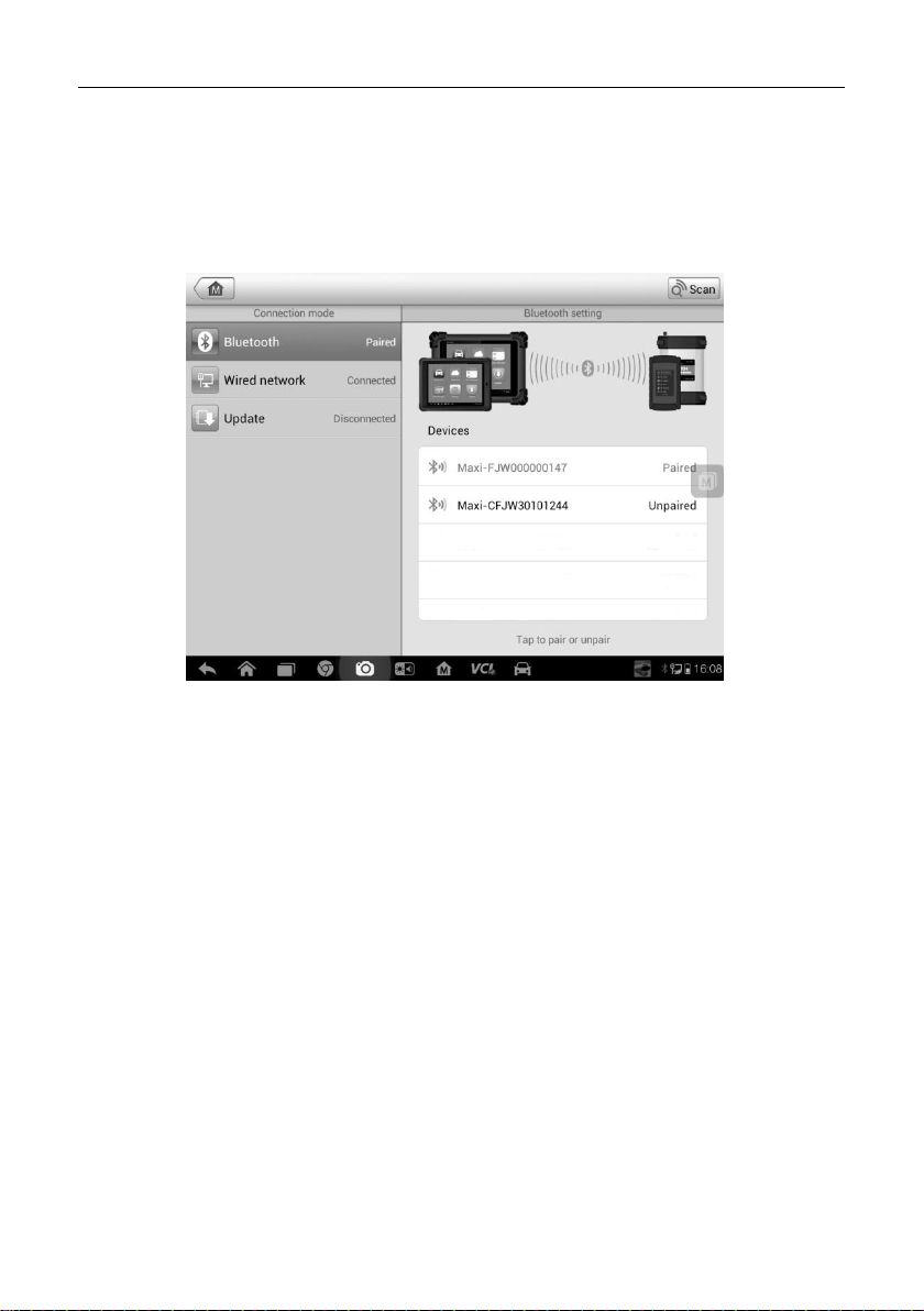
Chapter 10 VCI Manager Operations
This application allows you to pair up the MaxiSys Display Tablet with J2534
Programming Device, and to check t he communication status.
Figure 10-1 Sample VCI Manager Screen
1. Connection Mode – there are three connect ion modes available for selection.
The connection state is displayed alongside.
Bluetooth Paring – when paired to a Bluetooth device, the connection state
displays as Paired; otherwise it di s pl ays as Unpaired.
Wired Network Connection – when connected to a Local Area Net work, the
connection status displays as Connected; otherwise it displays as
Disconnected.
Update (for VCI software on ly) – Update VCI software via inter net through
the MaxiSys tablet network us ing U S B connection
Select a conne c tion mode to manage and set up connection.
2. Settings – this sec tion allows you to manage wireless p airing or set up network
connection.
Bluetooth Setting – searches and displays the type and a partial serial
93
 Loading...