

Page 1

Trademarks
Autel®, MaxaeroTM, X-MemoTM and X-StarTM are trademarks of Autel Aerial
Technology Co., Ltd., registered in China, the United States and other
countries. All other marks are trademarks or registered trademarks of their
respective holders.
Copyright Information
No part of this manual may be reproduced, stored in a retrieval system or
transmitted, in any form or by any means, electronic, mechanical,
tocopying, recording, or otherwise, without the prior written permission of
pho
Maxaero.
Disclaimer of Warranties and Limitation of Liabilities
All information, specifications and illustrations in this manual are based on
the latest information available at the time of printing. Maxaero reserves the
right to make changes at any time without notice. While information of this
manual has been carefully checked for accura
the completeness and correctness of the contents, including but not limited
to the product specifications, functions, and illustrations.
cy, no guarantee is given to
Use the products within the limits permitted by local laws and regulations. In
purchasing the products, the buyer/user agrees to bear full responsibilities of
the results of using this product. Maxaero will not be liable for any direct
damages or for any sp
economic consequential damages (including lost profits).
IMPORTANT:
manual carefully, paying extra attention to the safety warnings and
precautions.
Before operating or maintaining this unit, please read this
ecial, incidental, or indirect damages or for any
i
Page 2

Safety Information
For your own safety and the safety of others, and to prevent damage to the
product and other properties, it is important that the instructions and all
safety information presented throughout the product manuals be read and
understood by all persons operating, or coming into contact with, the
product.
IMPORTANT:
This product is not intended for use by children without adult
supervision. Do not use with incompatible components or alter this product
in any way inconsistent with the instructions provided by Maxaero.
z
Fly with an experienced pilot for the first flight is strongly recommended.
z
Fly in open and safe area; keep away from people and moving vehicles
especially when taking-off and landing.
z
Remove the batteries before assembly or when not in use.
z
Keep away from the moving and powered parts especially rotating
propellers.
z
Remove all propellers during configuration and setup.
z
Keep the small or electrical parts out of the reach of children.
z
Keep all the parts dry and clean.
z
Keep away from heat sources or humid and hostile environments.
z
Make a thorough preflight check before each flight.
z
Remove the propellers when testing the motors’ operation.
z
Make sure the batteries of all devices (aircraft, remote controller,
camera, and mobile) are fully charged.
z
Make sure the failsafe function of your remote controller is enabled
before take-off.
z
Do not fly in GPS mode when less than 6 satellite signals are received.
z
Keep away from electromagnetic interference.
z
Use with only authorized accessories approved or provided by Maxaero.
ii
Page 3

About Battery Usage
The product is powered by a built-in Lithium-ion Polymer battery.
LiPo/Li-Ion batteries can be extremely hazardous and special attention is
required during usage. Read and follow all safety messages and instructions
presented to avoid personal injuries or property damages.
DANGER:
The built-in Lithium-ion Polymer battery is factory replaceable
only; incorrect replacement or tampering with the battery pack may cause an
explosion.
z
Do not use a damaged battery charger.
z
Do not disassemble or open, crush, bend or deform, puncture or shred.
z
Do not modify or remanufacture, attempt to insert foreign objects into
the battery, expose the battery to fire, explosion or other hazards.
z
Disconnect and remove the Li-Po battery from the aircraft after use to
prevent trickle discharge. During storage, make sure the battery charge
does not fall below 3V.
z
Stop using or charging the battery immediately whenever the battery
starts to swell, smoke or leak.
z
Only use the charging device that has been qualified with device per the
standard. Use of an unqualified battery or charger may present a risk of
fire, explosion, leakage, or other hazards.
z
The heavier the payload, the shorter the flight time will be as more
battery power may be consumed.
z
The battery recharging time varies depending on the remaining battery
capacity.
z
Battery life inevitably shortens over time.
z
Since over charging may shorten battery life, remove the battery or the
device from its charger once it is fully charged. Unplug the charger once
charging is complete.
iii
Page 4

z
Leaving the product in extreme environments may reduce the capacity
and life of the battery. Always keep the battery within normal
temperatures.
z
Completely discharge the battery prior to disposal.
z
Dispose of the battery properly.
For Services and Support:
http://www.maxaero.com
0086-755-86147779 (China)
Support@maxaero.com
Or contact your local selling agent for technical assistance in all other
markets.
iv
Page 5

Contents
DISCLAIMER OF WARRANTIES AND LIMITATION OF LIABILITIES
SAFETY INFORMATION
ABOUT BATTERY USAGE
CHAPTER 1 USING THIS MANUAL
1.1 C
ONVENTI ONS
1.1.1 B
1.1.2 T
1.1.3 N
1.1.4 H
1.1.5 P
CHAPTER 2 GENERAL INTRODUCTION
2.1 IN T
2.2 A
IRCRAFT
2.2.1 F
2.2.2 B
2.2.3 F
2.2.4 A
2.2.5 3-
2.2.6 C
2.3 R
EMOTE CONTROLLER
2.3.1 F
2.3.2 R
...................................................................................... II
...................................................................................III
.................................................................... 1
......................................................................................... 1
OLD TEXT
......................................................................................... 1
ERMINOLOGY
OTES AND IMPORTANT MESSAGES
YPERLINKS
ROCED URE S
.................................................................................... 1
........................................................... 1
....................................................................................... 2
...................................................................................... 2
............................................................. 3
HE BOX
............................................................................................ 3
.............................................................................................. 7
UNCTIONAL DESCRIPTION
UILT-IN SMART FLIGHT SYSTEM
LIGHT
LED I
NDICATOR LIGHT
IRCRAFT BAT T ER Y
AXIS CAMERA GIMBAL
AMERA
......................................................................................... 18
...................................................................... 7
............................................................... 9
................................................................ 11
............................................................................. 12
...................................................................... 16
............................................................................. 20
UNCTIONAL DESCRIPTION
EMOTE CONTROLLER INDICATOR LIGHTS
.................................................................... 21
................................................... 24
............................... I
2.3.3 TECHNICAL SPECIFICATIONS................................................................ 26
CHAPTER 3 PRE/POST-FLIGHT OPERATIONS
3.1 P
REPARING AIRCRAFT
3.1.1 R
3.1.2 I
3.1.3 C
3.1.4 I
3.1.5 M
.............................................................................. 27
EMOVING GIMBAL LOCK
NSTALLING PROPELLERS
HARGING FLIGHT BAT T ER Y
NSTALLING AND REMOVING THE BAT TE R Y
OUNTING THE CAMERA
..................................................................... 27
....................................................................... 28
................................................................... 29
..................................................................... 31
................................................... 27
.................................................. 30
Page 6

3.2 P
3.3 P
3.4 I
CHAPTER 4 FLIGHT OPERATIONS
4.1 P
4.2 C
4.3 R
4.4 X-S
4.5 PC A
REPARING REMOTE CONTROLLER
3.2.1 RE-
3.3.1 I
3.3.2 R
3.3.3 E
3.3.4 RE-
3.4.1 R
PAIRING REMOTE CONTROLLE R
REPARING MOBILE DEVICE
NSTALLING MOBILE APP
EGIST ERING USER ACCOUNT
STABLISHING
PAIRING
NSTALLING PC AID SUITE
EGIST ER PC AID ACCOUNT
X-S
TA R WIFI NETWORK
X-S
TAR WIFI NETWORK
....................................................................... 34
...................................................................... 35
......................................................................... 38
................................................................... 40
REFLIGHT CHECKLIST
ALIBRATING COMPASS
EMOTE CONTROLLE R AND FLIGHT OPERATIONS
4.3.1 M
4.3.2 F
4.3.3 L
4.3.4 O
4.4.1 X-S
4.4.2 C
4.4.3 G
4.4.4 C
4.4.5 S
OTOR STAR T-UP AND TAKE-OFF
LIGHT ATTITUDE CONTROLS
ANDING AND MOTOR SHUT-DOWN
PERATIONS OF SMART FLIGHT FEATURES
TAR MOBILE APP OPERATIONS
TAR MOBILE APP MAIN MENU
AMERA OPERATIONS
ROUND STATI ON OPERATIONS
ONFIGURATION OPERATIONS
ETTINGS OPERATIONS
ID OPERATIONS
.............................................................................. 40
............................................................................ 41
......................................................................... 55
........................................................................ 77
............................................................................... 79
............................................................... 32
........................................................... 33
................................................................ 35
...................................................... 35
........................................................ 36
.................................................................. 38
.............................................. 43
............................................................ 43
.................................................................. 44
........................................................ 47
.................................................. 49
............................................................... 53
.......................................................... 53
.............................................................. 61
................................................................ 67
CHAPTER 5 MAINTENANCE AND SERVICE .............................................. 82
5.1 MAINTENANCE INSTRUCTIONS ................................................................ 82
5.2 TROUBLESHOOTING CHECKLIST ............................................................... 83
5.3 SERVICE PROCEDUR ES ........................................................................... 85
CHAPTER 6 WARRANTY ......................................................................... 87
Page 7

Chapter 1 Using This Manual
This manual contains product usage instructions.
Some illustrations shown in this manual may contain optional modules or
accessories that are not included on your system. Contact your sales
representative for availability of other modules and optional accessories.
1.1 Conventions
The following conventions are used.
1.1.1 Bold Text
Bold emphasis is used to highlight selectable items such as
buttons and menu options.
Example:
z
Tap OK.
1.1.2 Terminology
The term “select” means highlighting a button or menu item and
tapping it to confirm the selection.
1.1.3 Notes and Important Messages
The following messages are used.
Notes
A
NOTE
explanations, tips, and comments.
provides helpful information such as additional
Important
IMPORTANT
result in property damages or personal injuries.
indicates a situation which, if not avoided, may
1
Page 8

1.1.4 Hyperlinks
Hyperlinks, or links, that take you to other related articles,
procedures, and illustrations are available in electronic documents.
Blue colored text indicates a selectable hyperlink.
1.1.5 Procedures
An arrow icon indicates a procedure.
Example:
¾
To use the camera:
1 Tap the
Camera
button. The camera screen opens.
2 Focus the image to be captured in the view finder.
3 Tap the blue circle. The view finder now shows the
captured picture and auto-saves the taken photo.
2
Page 9
Chapter 2 General Introduction
The X-Star is the new generation of smart unmanned aircraft system. It is
extremely easy to fly and reliable. Featuring the advanced built-in Smart
Flight System, a high-performance remote control, combined with a powerful
mobile app, the X-Star system allows safe and stable flight maneuvers both
manually and automatically. The stabilized 3-axis camera gimbal offers ideal
solutions for smooth aerial photographing and video recording, making the
system incredibly versatile and powerful.
This manual describes the construction and operation of the product, and
how it works to deliver flight maneuvers for ideal aerial photographing
solutions.
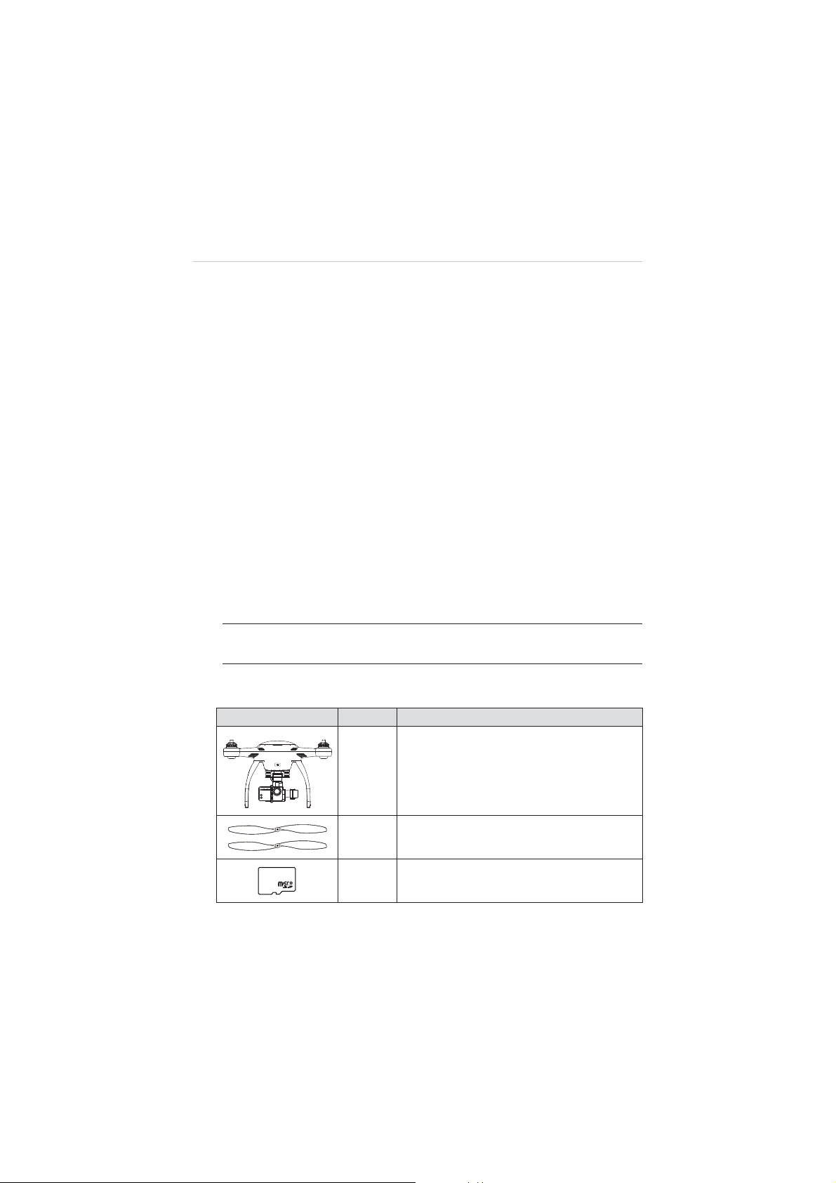
2.1 In The Box
The complete X-Star ST1 standard package comes with the following
items. Before using the system, check if everything is included.
NOTE:
The package may or may not contain the camera and the
camera accessories kit depending on the Gimbal system purchased.
Table 2-1
Package Contents
Image Qty. Description
Aircraft
X1
Integrated with a 3-axis Gimbal and a
Camera (optional)
Propeller
4 with red nut, 4 with white/black nut
8GB MicroSD Card
Inserted in the Camera MicroSD card slot
3
8GB
X4 Pair
X1
Page 10
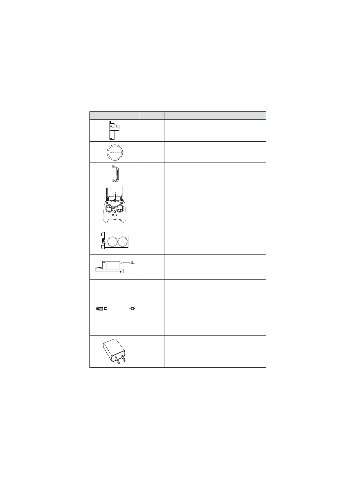
Image Qty. Description
Gimbal Lock
X1
Protects the Camera Gimbal when not in
use
Lens Cap
X1
Protects camera lens from dust and
scratches
X1
X1
X1
X1
X1
X1
Gimbal Camera Securing Bracket
Secures the camera to the mount
Remote Controller
Phone holder and 5000mAh Li-Ion battery
included
Aircraft Battery
6400mAh Rechargeable Li-Po battery
Provides
ʈ
25 minutes of flight time if fully
charged.
Aircraft Battery Charger
Connects the Aircraft Battery to the external
power port for AC/DC power supply
Micro-USB Cable
z
Connects the Remote Control to the
USB Power Adapter for power supply;
z
Connects the Aircraft or the Remote
Control to the PC for firmware update or
configurations;
z
Connects the Camera Gimbal to the PC
for camera file transfer.
USB Power Adapter
Connects to the external power port and
provides power supply to the Remote
Control through the Micro-USB Cable.
4
Page 11
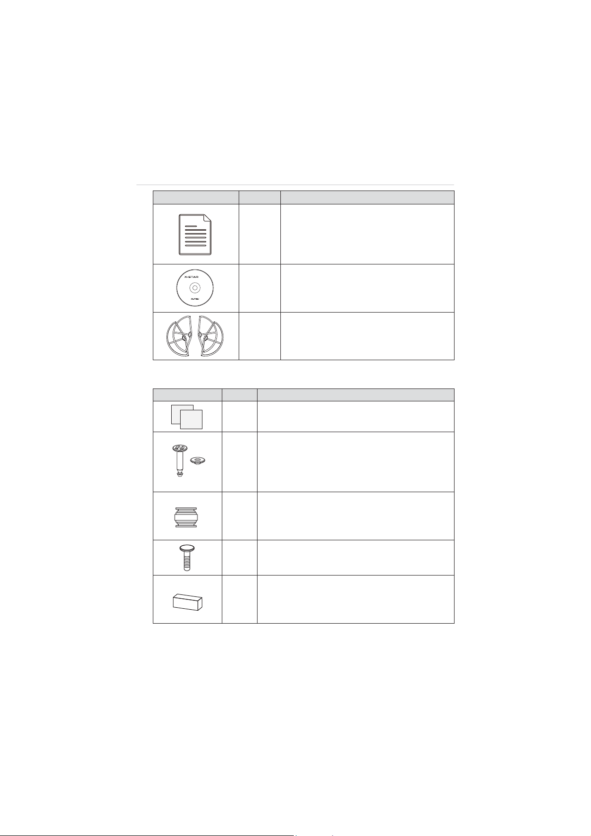
Image Qty. Description
Manuals
z
User Manual
z
X3
X-Star ST1 Quick Start Guide
z
Camera Mount Quick Start Guide (for
camera attached gimbals)
PC Suite
Suitable for:
ವWindows 8
ವWindows 7
ವWindows Vista
:indows XP
Autel Intelligent Technology Corp., Ltd.
All Rights Reserved
www.autel.com
X1
CD
Includes PC Aid Program and User
Manual, etc.
Optional
Acc.
Propeller Guards
Surround the propellers and protect them
from damage. (4 in 1 set)
Aircraft Maintenance Kit
Image Qty. Description
Indication Stickers
X2
Helps pilots to identify the front side of the aircraft.
Anti-drop Lock Pins
Fix the Camera Gimbal to the mounting rack
X2
connected to the aircraft to avoid dropping.
2 pins mounted on deliver; 2 extra supplied for
maintenance use
Vibration Absorber
Fixed in between the gimbal’s mounting rack and
X4
the Gimbal to reduce vibrations and avoid
mechanical damage.
Spare Screws
X11
M3X5 (6pcs); M3X8 (5pcs)
Rubber Pad
Stick to the 4 corners at the bottom of the landing
X4
gear to support the aircraft when it is on the
ground, and when it is landing or taking off.
5
Page 12
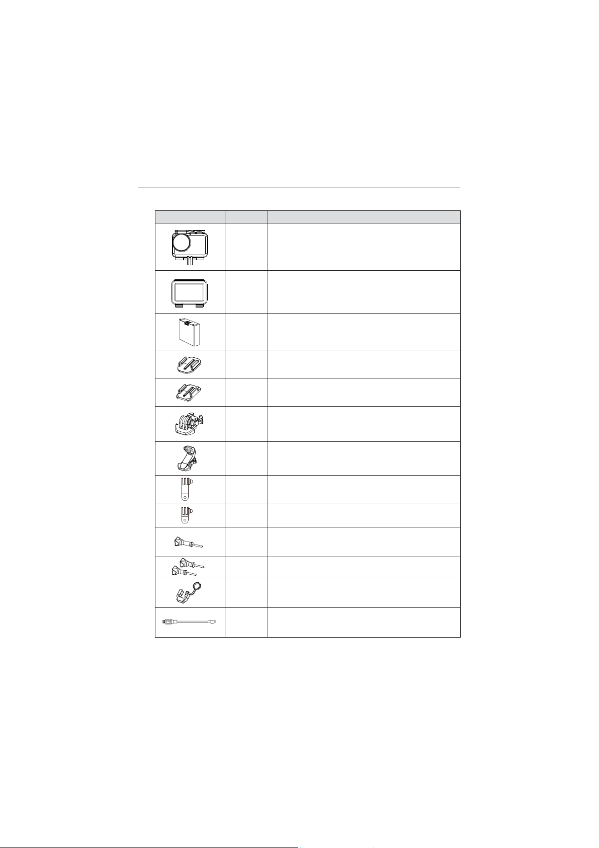
Camera Accessories Kit
Image Qty. Description
X1
X2
X1
X1
X1
X2
X1
X1
X1
Waterproof Housing
Allows underwater photographing.
Backdoors
z
Opened (without cover, not waterproof)
z
Covered (with touchable screen protector)
Camera Battery
940mAh Rechargeable Li-Po Battery installed on
delivery
Flat Mount
Curved Mount
Short Connectors
Long Connector
90qC Rotate Connector (long)
90qC Rotate Connector (short)
X1
X2
X1
X1
Connecting Screw (long)
Connecting Screws (short)
Fixing Rubber
Prevents the Rotate Connector from slipping off.
Mini USB Cable
Connects the Camera to the PC for file transfer.
6
Page 13
2.2 Aircraft
The X-Star aircraft is a quadcopter with an integrated stabilized camera
gimba. The camera may or may not be supplied depending on the
gimbal model purchased. The Micro-USB port on the aircraft supports
convenient connection that allows easy flight configuration and system
update through the PC Aid Software.
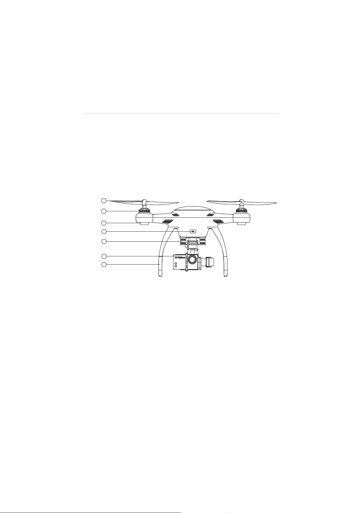
2.2.1 Functional Description
Figure 2-1
Front Side
1. Propeller – 9.4 x 4.3 inch
2. Motor
3. Front LED Indicator Light – helps to identify the aircraft nose
4. Micro-USB Port – allows communication between the Smart
Flight System and the PC Aid program through USB
connection
5. 3-axis Camera Gimbal
6. Camera
7. Front Sticker – helps to identify the aircraft nose
7
Page 14
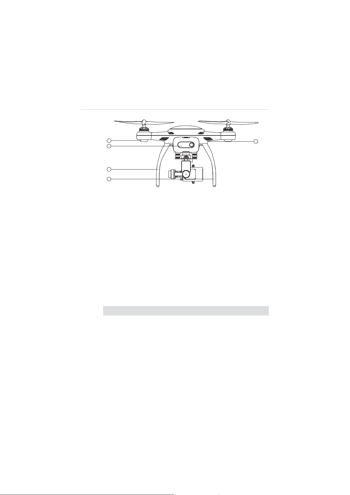
Figure 2-2 Rear Side
8. Rear LED Indicator Light – indicates flight status
9. Aircraft Battery
10. RC Pairing Button – prepares the aircraft to perform pairing
with the Remote Control, see 3.2.1 Re-pairing Remote
Controller on page 33 for detailed instructions
11. Landing Gear
12. Compass
Aircraft Specifications
Table 2-2 Aircraft Specifications
Item Descriptions
Max. Payload 0.8kg
r
Hover Precision Horizontal:
Max. Yaw Rate 180
q
/s
Max. Inclination Angle GPS Mode: 30
2m; Vertical: r1m;
q
; ATTI Mode: 30
Max. Ascent/Descent Speed Ascent: 6m/s; Descent: 2m/s
Max. Cruising Speed 12m/s
Diagonal Wheelbase 352mm
8
q
Page 15

Item Descriptions
Propeller Size 9.4”x4.3”
WiFi Frequency 2.4GHz
Receiver Frequency 5.8GHz
Flight Modes
z
z
Operating Environment Temperature0q
Storage Temperature 0
Weight (Battery & Propellers
1.1kg
included)
2.2.2 Built-in Smart Flight System
The X-Star features the Built-in Smart Flight System which
enables autopilot flight control that provides great ease of use and
stability. The Smart Flight System consists of various modules
such as the GPS receiver, the Compass and the Inertial
Measurement Unit (IMU). It works as the central computer of the
aircraft and supports various functions such as Intelligent
Orientation Control (IOC), Go Home, and Failsafe, etc.
Table 2-3 Smart Flight System Modules
Module Descriptions
An electronic device consists of a gyroscope,
IMU
Compass
accelerometer and magnetometer that measures flight
velocity, gravitational force and orientation.
Reads geomagnetic information and assists the GPS
receiver for accurate position calculation.
GPS
IOC
z
z
C~50qC(32qF~122qF)
q
C~45qC(32qF~113qF)
ATTI
Waypoint
GPS Receiver
Receives GPS signals and determines the latitude and
longitude of the aircraft location.
9
Page 16
Table 2-4 Smart Flight System Functions
Function Descriptions
Configures the aircraft to fly in the direction relative to
IOC
the home point or consistent to the initial aircraft
orientation, instead of its nose and tail.
Go Home
Commands the aircraft to return to and land on the
specified home point.
Enables the aircraft to take automatic protection
Failsafe
measure when communication with the remote control
is lost, to prevent damage or injuries.
NOTE:
A home point is usually memorized by the system each time as the
point where the aircraft takes off. The home point can also be repositioned
during flight. See 4.3.4 Operations of Smart Flight Features on page 49 for
details.
Table 2-5 Supported Flight Modes
Flight Modes Descriptions
Stabilizes and holds the aircraft in position on stick
release when activated (requires at least 6 GPS satellite
GPS Mode
signals)
, which offers more stable and smooth flight
maneuvers. It allows the safety features including Go
Home, IOC and Failsafe for safer flight experiences.
Stabilizes and holds the aircraft to the altitude on stick
release. The ATTI mode provides more agility in flight
ATTI Mode
controls with attitude and speed mixture. It allows the
safety features including Go Home, IOC and Failsafe for
safer flight experiences.
Provides freer and more agile flight maneuvers
depending on 100% mechanical driving by controls of
the command sticks.
Manual Mode
This mode is only recommended for experienced pilots,
and is disabled by default. It can be activated through
flight configurations with the PC Aid or X-Star Mobile
App.
10
Page 17

2.2.3 Flight LED Indicator Light
Ș
The LED Indicator Lights on the aircraft can be found at both the
front and rear sides. The Front Indicators are mainly used for
helping pilots to identify the position of the aircraft nose, and the
Rear Indicators are used for showing the current flight status of
the aircraft.
The LED Indicator Lights will light up when the aircraft is turned on.
The table below describes the definitions of the LED Indicator
Light status.
Ș - Indicates solid light;
Ȗ – Indicates flashing light;
R – Indicates red colored light;
G – Indicates green colored light;
Y – Indicates yellow colored light
R-
Ș
” sta
nds for
Example: “
Table 2-6 Definitions of Flight LED Indicator Light Status
LED Indicator Status Descriptions
R-Ș(Front LEDs)
RED SOLID
Light up when the motors start spinning
after the aircraft is powered on, indicating
the position of the aircraft nose.
light.
G-Ȗ(Rear LEDs)
Y-Ȗ(Rear LEDs)
R-Ȗ-Slow
(Rear LEDs)
Displayed when in GPS Flight Mode. This
mode can be activated only when more
than 6 GPS satellites are found.
Displayed when in non-GPS Flight mode,
or when less than 6 GPS satellites are
found.
Displayed when communication with the
remote controller is lost.
11
Page 18

LED Indicator Status Descriptions
Ȗ
R-
Ȗ
-Quick
(Rear LEDs)
Y-Ȗ(Front & Rear LEDs)
Y-Ș(Rear LEDs)
G-Ș(Rear LEDs)
R-Ȗ(Front & Rear LEDs)
2.2.4 Aircraft Battery
The Aircraft Battery is a rechargeable Li-Po Battery with the
capacity of 6400mAh specially designed for the X-Star aircraft. It
can only be charged by the charger supplied with the X-Star
package, and can provide sufficient power for about 25 minutes of
continuous flight if fully charged.
Light up when battery voltage is less than
20%.
Indicates compass calibration is required.
See 4.2
Calibrating Compass
on page
41 for detailed instructions.
Displayed during the 1
st
step of compass
calibration.
Displayed during the 2
nd
step of compass
calibration.
Indicates hardware problems possibly
caused by:
z
IMU deviation or abnormal
z
Compass error
z
Remote Controller recalibration
required
See 5.2
Troubleshooting Checklist
on page 83 for detailed information.
The Aircraft Battery features several smart functionalities for
charge-discharge management that improves the battery’s
longevity.
12
Page 19

Table 2-7 Aircraft Battery Features
Feature Descriptions
Balancing
Balances the voltage of each battery cell to
prevent overcharging or over-discharging.
Retrieves and transfers battery info, including
Communication
battery level, current, voltage, battery life, and
temperature to the aircraft and the controller.
Charging Temperature
Detection
Low Battery Protection
Stops battery charging when environment
temperature is out of allowed range.
Activates alarm when battery level is less than
20%.
LED Capacity Indicator Indicates current battery level.
z
Automatically stops charging when battery
Overcharging &
Over-discharging
Protection
voltage reaches 12.8V to prevent damage.
z
Automatically stops discharging when
battery voltage reaches 8.4V to prevent
damage.
z
Cuts off power supply when a short circuit
occurs to prevent damage.
Short Circuit Protection
z
All LED lights on the battery front panel will
flash green w
hen a short circuit is
detected.
Power Saving
Turns the battery off automatically after 10
minutes of inactivity.
13
Page 20
Aircraft Battery Specifications
Table 2-8 Aircraft Battery Specifications
Item
Battery Type
Capacity
Battery Voltage
Charging
Environment Temperature
Discharging
Environment Temperature
Storage Temperature & Humidity Temp: -10
Descriptions
Rechargeable Li-Po Battery
6400mAh
11.1V
0
q
C~40qC(32qF~104qF)
-20
q
C~60qC(-4qF~140qF)
q
C~45qC(14qF~113qF);
Humidity: 5~70%
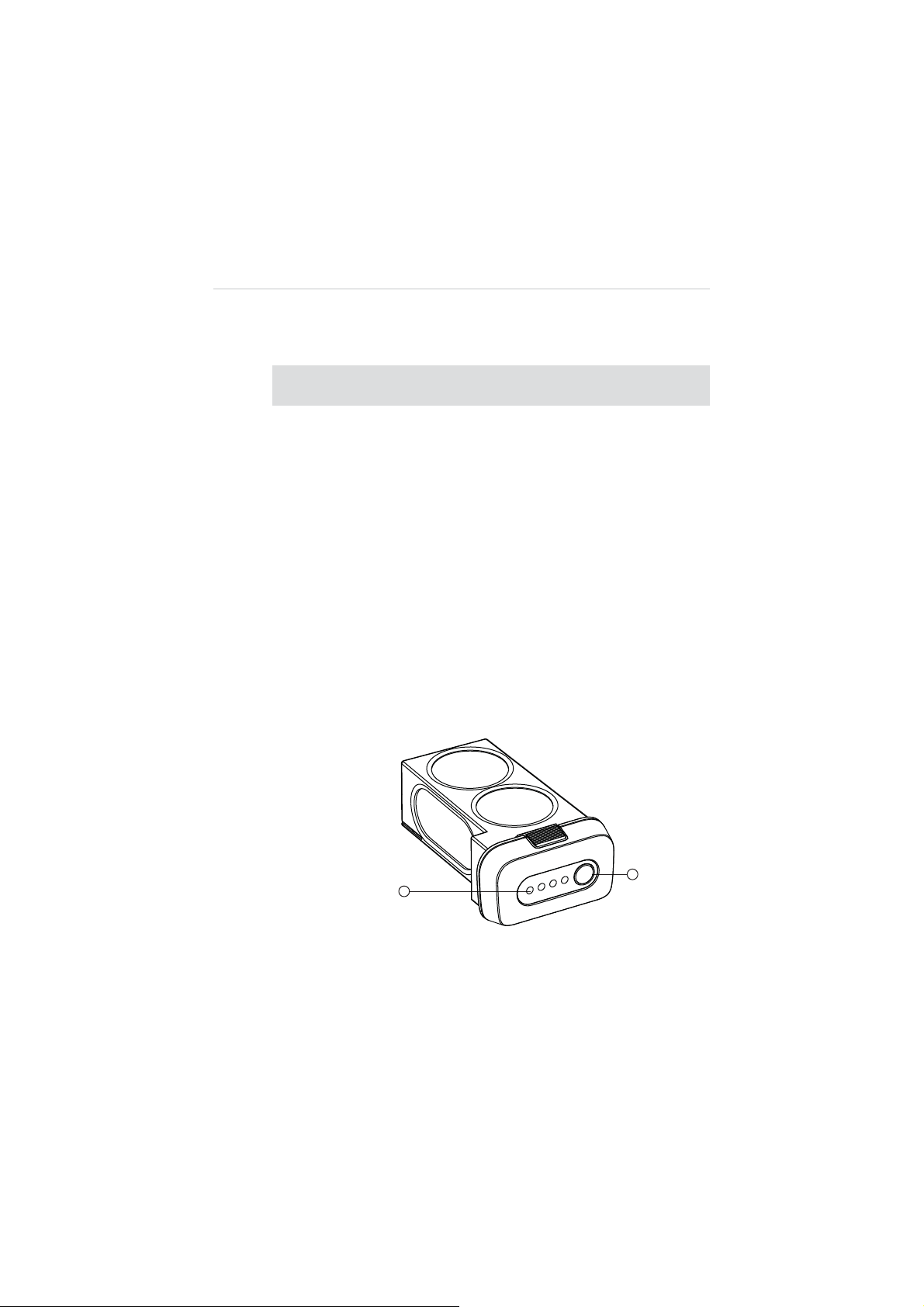
Functional Descriptions
The Aircraft Battery front panel contains 4 LED Capacity Indicator
Lights and 1 Power Button.
Figure 2-3 Aircraft Battery
14
Page 21

1. Capacity Indicator Lights
2. Power Button – allows you to check the battery level and turn
on/off the battery
A. To turn on the battery and power up the aircraft, long
press the Power Button for 3 seconds. The Capacity
Indicator Lights will illuminate and indicate the current
battery level. (See Table 2-9 on page 15 for details.)
B. To turn off the battery, long press the Power Button for 3
seconds.
C. To check the current battery level when the battery is
powered off, short press the Power Button once, and
the Capacity Indicator Lights will illuminate and indicate
the current battery level.
The table below describes the specific battery levels indicated by
the Capacity Indicator Lights during discharging process.
Table 2-9
Ș
- Indicates solid green light; Ȗ- Indicates flashing green light
Indicator Status Battery Level
See 3.1.3 Charging Flight Battery on page 29 for more
details.
Capacity Indicator Status while Discharging
90%~100%
75%~89%
60%~75%
50%~60%
40%~50%
25%~40%
15%~25%
0%~15%
15
Page 22
2.2.5 3-axis Camera Gimbal
The 3-axis Camera Gimbal mounted to the aircraft is specially
designed to allow smooth aerial photographing to minimize
camera vibration or shake.
It is powered through the Aircraft Battery, and therefore it is turned
on at the same time with the aircraft. A self-test is performed each
time the Gimbal starts up.
The X-Star system is compatible with more than one gimbal model.
Depending on the specific gimbal model purchased, the gimbal
may or may not have a camera mounted, and the camera, if
supplied, may or may not be detachable.
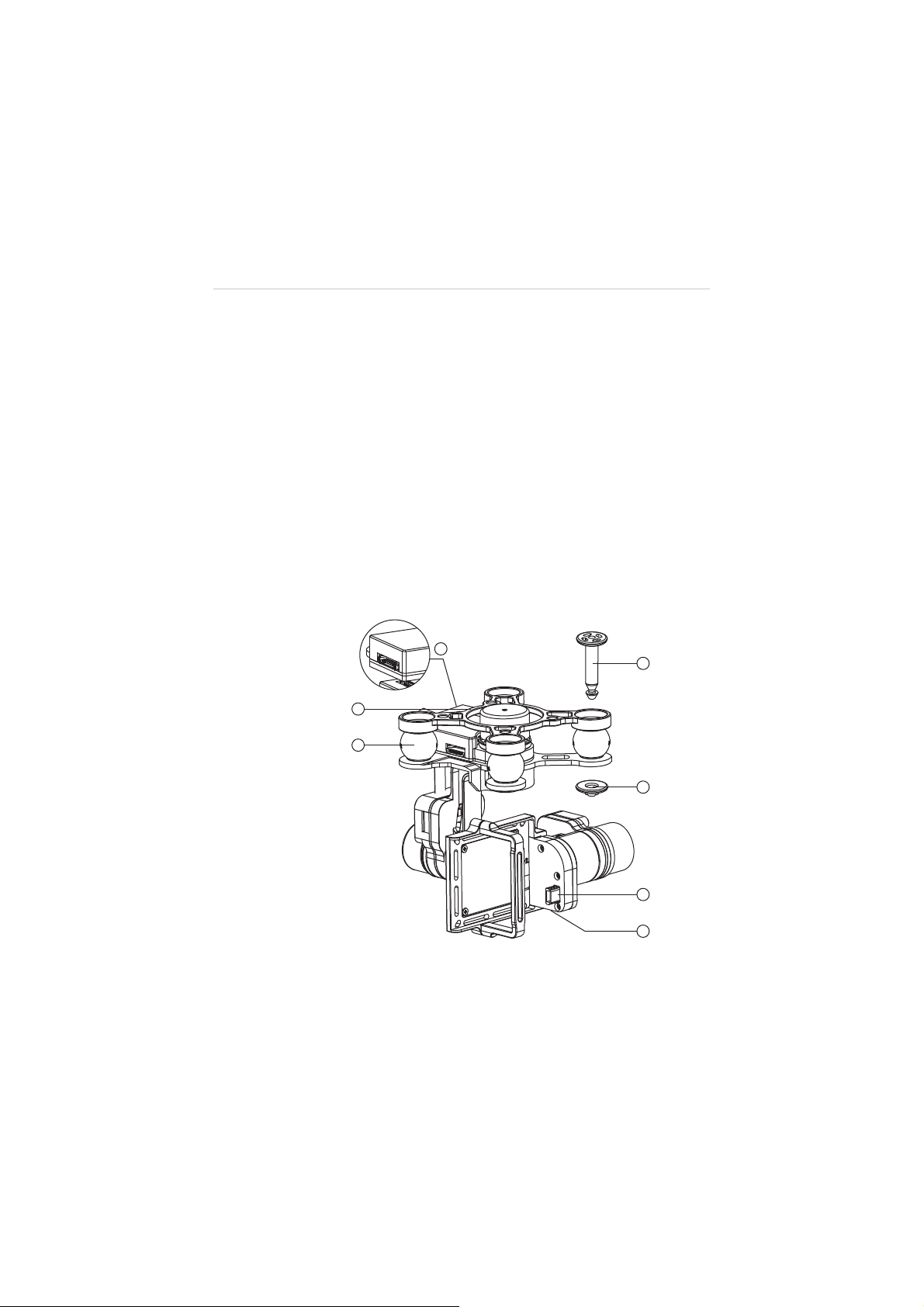
Figure 2-4
'
(
Standard 3-axis Camera Gimbal Sample
16
Page 23

1. Mounting Rack
2. Vibration Absorber
3. Anti-drop Lock Pin
A. Press the pin through the hole at the corner of the
gimbal’s mounting rack with the Vibration Absorber in
between;
B. Press the stud from the bottom up to lock the pin.
4. Aircraft Communication Port
5. Camera Connector
6. Micro-USB Port – connects to the PC using the Micro-USB
cable supplied for camera file transfer. Do not disconnect the
camera from the gimbal while transferring.
Camera Gimbal Specifications
Table 2-10
Camera Gimbal Specifications
Item Descriptions
Operating Current
340mA@12V (Camera Off)
600mA@12V (Camera On)
Operating
Environment Temperature
Control Accuracy
Controllable Range
Maximum Angular Velocity
NOTE:
The Camera Gimbal comes with a gimbal lock attached
q
C~45qC
0
Tilt/Roll:
Yaw:
r
Pitch: 0
q
/s (r150°/S)
90
r
0.02
q
0.03
q
q
~90q(-130~+45°)
which protects the gimbal from incidental rotation to avoid damage.
Remove the clamp before powering up the aircraft (see
on page 27
).
17
Figure 3-1
Page 24
The 3-axis Camera Gimbal for X-Star supports 2 working
modes:
1. FPV Mode – synchronizes the camera gimbal movements
with the aircraft to provide a real time video piloting
experience from a first-person view.
2. Non-FPV Mode – enables stabilized camera tilting control for
creative aerial photography.
See 4.4.4 Configuration Operations on page 67 for detailed
configuration instructions.
2.2.6 Camera
The Camera mounted to the Aircraft is stabilized by the 3-axis
Camera Gimbal. Depending on the gimbal’s working mode applied,
it enables both real time FPV piloting control and smooth aerial
photographing and video recording based on the pilot’s needs.
See 3-axis Camera Gimbal on page 16 for more information.
The Camera has a built-in Li-Po battery, which can be charged
either by the Aircraft Battery when mounted to the gimbal on the
aircraft, or by connecting to the PC using the Mini USB Cable
supplied.
Turn on the camera before powering up the aircraft.
mode
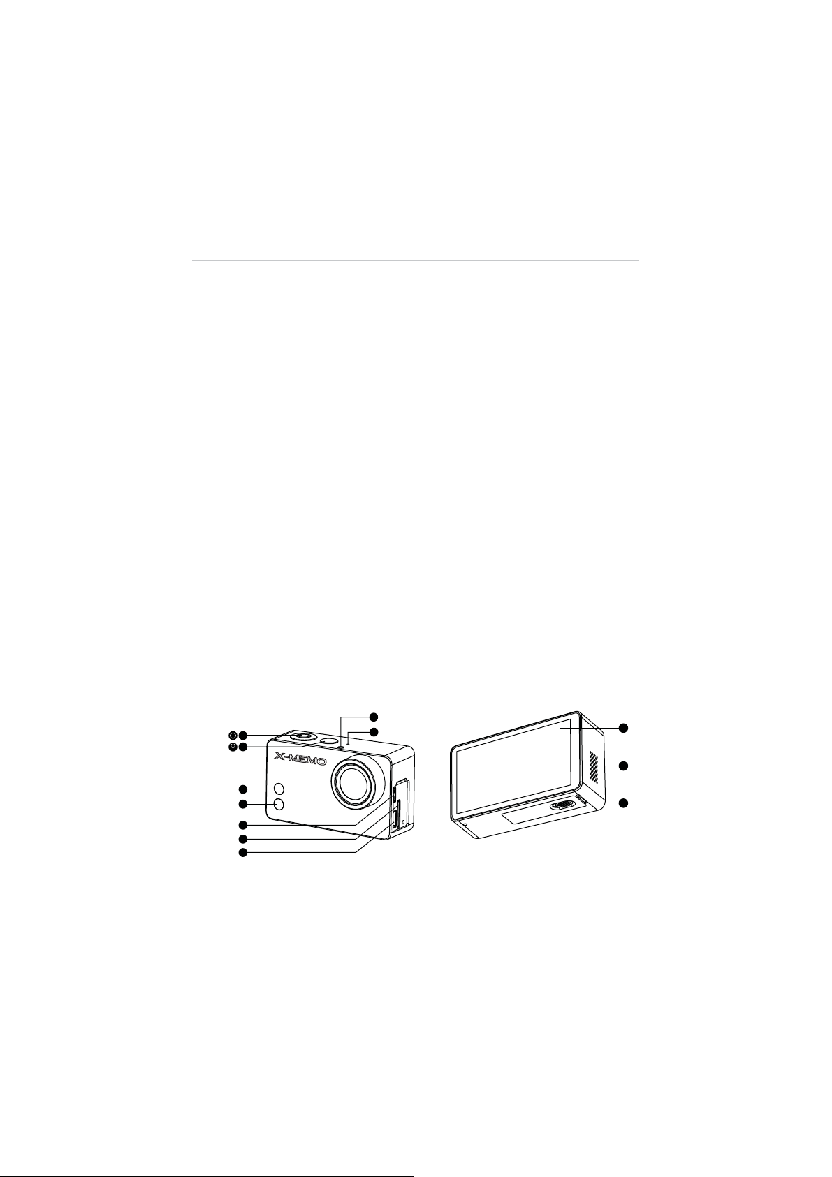
Figure 2-5
18
Camera 6-Side View
Page 25
1. Shutter/Select Button 2. Power/Mode Button
3. WiFi Status Light (blue) 4. Camera Status Light (red)
5. Micro HDMI Port 6. MicroSD Card Slot
7. Mini USB Port 8. LED Status Light
9. Microphone 10. Touch Screen
11. Audio Speaker 12. Battery Compartment Lock
Table 2-11
Camera Functional Descriptions
Name Description
1. Shutter/Select
Button
Press this button to:
A. Take photos or videos
B. Make selections on menus
A. Press this button once to turn on the
camera.
B. Press and hold for 3 seconds to turn off
the camera.
2. Power/Mode Button
C. When the camera is powered on,
pressing this button allows you to switch
among the camera
Playback
sequence.
3. WiFi Status Light
(blue)
4. Camera Status
Light (red)
Indicates the WiFi communication status.
Indicates the working status of the camera
when taking photos or videos.
Connects the camera to a compatible
5. Micro HDMI Port
computer monitor, digital television, or video
projector for high definition video file transfer.
6. MicroSD Card Slot
7. Mini USB Port
8. LED Status Light
Stores camera files.
Connects to and communicates with the
gimbal or the PC for file transfer.
Synchronizes with the Camera and WiFi
Status lights for convenient identification.
and the
Modes
Setting
, the
options in
19
Page 26

Name Description
9. Microphone
Records sound when taking videos.
10. Touch Screen
11. Audio Speaker
12. Battery
Compartment Lock
NOTE:
The camera lens is covered by a lens cap on delivery to protect the
camera lens from dust and scratches. Remove the lens cap before use.
Works as the display monitor featuring
intuitive touch control.
Makes alert sounds and plays audios.
Locks or unlocks the Battery Compartment.
Contains a 940mAh rechargeable Li-Po
battery.
Camera Specifications
Table 2-12
Item Descriptions
Operating Environment Temperature -10qC~50qC(14qF~122qF)
Effective Pixels 12MP
HD Recording Resolution 1080P/60fps
Max. Recording Field of View 160
Refer to the supplied camera manual for more operation instructions.
NOTE:
Camera Specifications
q
2.3 Remote Controller
The X-Star Remote Controller enables wireless communication with the
Aircraft through a 5.8GHz radio frequency band. The maximum working
range of the Remote Controller through RF signal in an open area is
about 400m when set as CE compliant, or about 800m when set as
FCC compliant.
20
Page 27
The built-in 2.4GHz WiFi module on the Remote Controller allows
self-generated WiFi network connection for real time flight and video
data transmission between the aircraft and the mobile device enabling
convenient controls of aerial photographing and remote piloting.
NOTE:
The X-Star WiFi Network is only established when the aircraft,
the Remote Controller and the mobile device are properly connected
through WiFi connection. See 3.3.3 Establishing X-Star WiFi Network
on page 35 for detailed instructions.
2.3.1 Functional Description
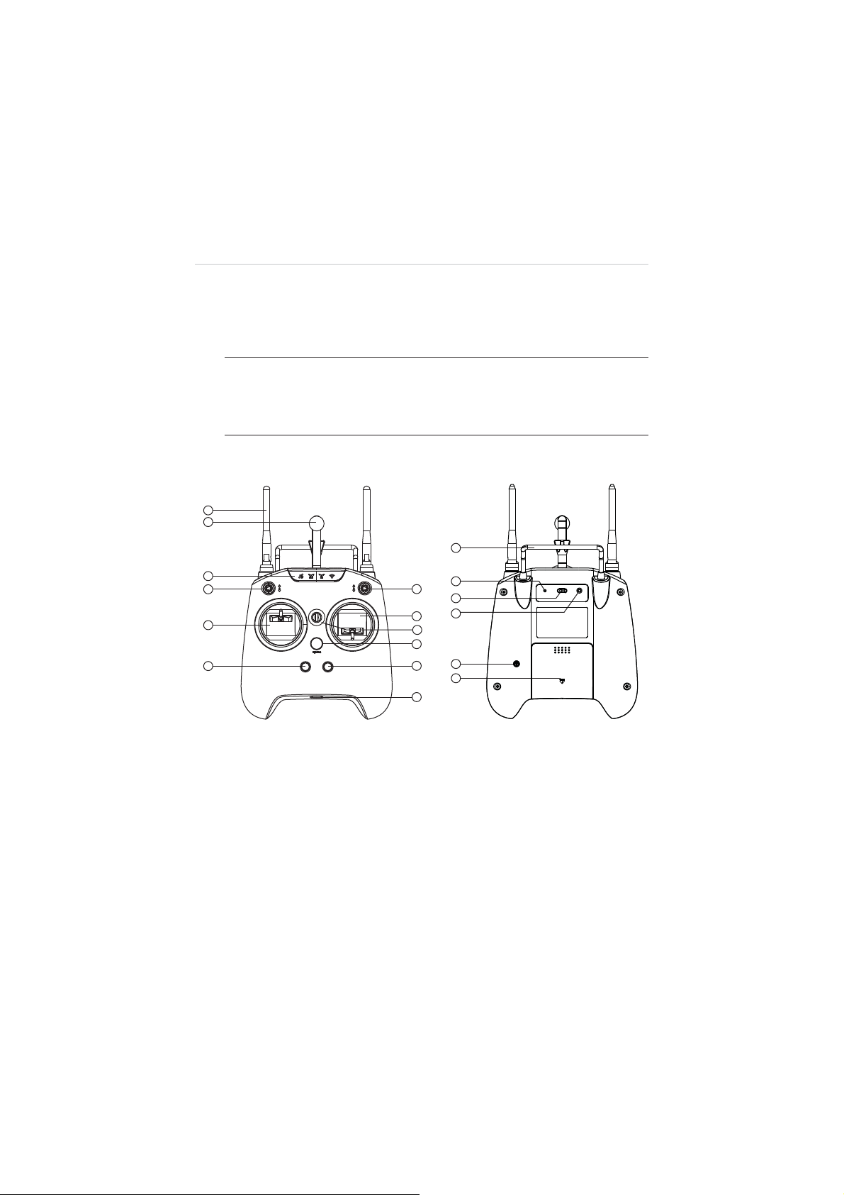
Figure 2-6
Remote Controller Front and Rear View
1. WiFi & RF Antennas 2. Mobile Holder
3. Indicator Light Panel 4. Smart Control Switch
5. Flight Mode Switch 6. Left Command Stick
7. Right Command Stick 8. Strap Hole
9. Power Button 10. Take-off Button
11. Landing Button 12. Micro USB Port
Re-Pair WiFi CE/FCC
21
Page 28

13. Support Stand 14. Re-pair Hole
15. WiFi Switch 16. CE/FCC Control Screw
17. Buzzer 18. Battery Compartment
Table 2-13
Remote Controller Functional Descriptions
Name Description
z
The 5.8GHz RF signal antenna
communicates with and transmits control
signals to the aircraft.
1. WiFi & RF Antennas
z
The 2.4GHz WiFi antenna receives and
transfers flight data and camera data to
the X-Star Mobile App.
Holds the mobile device with the X-Star
2. Mobile Holder
Mobile App installed with up to 90
adjustable viewing angle for optimum
visibility.
Indicates different status of:
z
GPS satellite signal strength
z
Aircraft battery level
3. Indicator Light Panel
z
RF remote control signal strength
z
WiFi communication
See 2.3.2 Remote Controller Indicator Lights
on page 24 for detailed information.
q
4. Smart Control Switch
5. Flight Mode Switch
Switch to activate the Smart Flight function
of IOC or Go Home controls.
Switch to change flight modes:
Up: GPS Mode
Middle & Down: ATTI Mode
22
Page 29

Name Description
Set by default:
Throttle Up and Down: ascends and
6. Left Command Stick
descends
Rudder Left and Right: yaws left and yaws
right
Set by default:
7. Right Command
Stick
Elevator Up and Down: forward and
backward
Aileron Left and Right: left and right
8. Strap Hole Attaches to a neck strap for easy portability.
Long press for 3 seconds to turn on/off the
remote controller, a quick buzz can be heard
at the same time.
9. Power Button
The power button shows solid green light
when the remote controller is turned on. See
2.3.2 Remote Controller Indicator Lights on
page 24 for detailed information.
When the motors start up, pressing this
button for 3 seconds commands the aircraft
10. Take-off Button
to take off and hover at an altitude of 2m.
A buzz sound can be heard at the same time
when activated.
Pressing this button for 3 seconds
11. Landing Button
commands the aircraft to land. A buzz sound
can be heard at the same time when
activated.
Connects the remote controller to the PC
12. Micro USB Port
through the Micro USB Cable supplied for
battery charging, firmware update or RC
configurations.
13. Support Stand
Holds up the remote controller at a 40
degree angle.
23
Page 30

Name Description
14. Re-pair Hole
Pressing the Re-pair Hole with a thin rod
allows re-pairing the X-Star WiFi network.
Switches on/off the WiFi module to allow
15. WiFi Switch
flight and video data transmission between
the aircraft and the mobile device.
z
Turn the control screw for a full clockwise
16. CE/FCC Control
Screw
turn to set as CE compliant;
z
Turn the control screw for a full
counter-clockwise turn to set as FCC
compliant.
17. Buzzer Makes alert sounds.
18. Battery Compartment Contains a rechargeable Li-Ion battery.
See 4.3 Remote Controller and Flight Operations on page 43 for
more instructions about the remote controller operations.
NOTE:
The Remote Controller makes an alert sound after 15
minutes of inactivity, and turns off automatically after 30 minutes of
inactivity.
2.3.2 Remote Controller Indicator Lights
There are 7 indicator lights on the remote controller, among which
4 are displayed on the Indicator Light Panel at the front top; the
other 3 indicators are displayed separately on the Power Button,
the Take-off Button and the Landing Button.
The Indicator Light Panel is activated when the WiFi switch at the
back of the remote controller is turned on. It displays in response
to the flight data received through the X-Star WiFi network, so
make sure to pair up the devices first.
NOTE:
solid red lights when the X-Star WiFi network is disconnected.
The 4 indicator lights on the Indicator Light Panel display
24
Page 31

The definitions for each of the Indicator Light are described in the
table below:
Table 2-14 Remote Controller Indicator Lights
Item Button Description
z
Shows green light when GPS mode is
enabled and more than 6 GPS satellite
GPS Signal
signals are received;
z
Shows red light when the GPS mode is
disabled or less than 6 GPS satellite
signals are received.
z
Shows green light when the aircraft
battery is sufficient;
z
Aircraft Battery
Shows yellow light when the aircraft
battery level is less than 20% (2
Low Battery Protection activated);
z
Shows red light when the aircraft battery
nd
Level
level is less than 10% (1st Level Low
Battery Protection activated).
z
Shows green light when communication
between the remote controller and the
aircraft through RF signals is active and
RF Signal
stable;
z
Shows red light when communication
between the remote controller and the
aircraft is lost.
WiFi Signal
RC Power
Shows green light when the X-Star WiFi
network is active and stable;
z
Shows green light when powered up;
z
Shows red-green flashing light when
the remote controller battery voltage is
low;
z
Shows red flashing light when charging.
25
Page 32

Item Button Description
Tak e Of f
Landing
Lights up when pressed, turns off when
released.
Lights up when pressed, turns off when
released.
2.3.3 Technical Specifications
Item Descriptions
Operating Frequency
(RF Receiver)
WiFi Repeater Frequency 2.4GHz
Operating Temperature 0
Storage Temperature -20
Communication Distance
(open area)
Transmission Power (EIRP) CE: 25mW; FCC:150mW;
Operating Current/Voltage WIFI ON: Max. 550mA@3.7V
Battery 5000mAh rechargeable Li-Ion
Power Consumption Max:2.2W
Weight (battery included) 610g
5.8GHz
q
C~50qC
q
C~75qC
CE:400m; FCC:800m;
Battery
26
Page 33

Chapter 3 Pre/Post-flight Operations
The X-Star features the user-friendly design that requires very simple
assembly to get the aircraft ready to fly. However, it is essential to read and
follow all the instructions and warnings in this manual, prior to assembly,
setup or use, in order to operate correctly and avoid damages or injuries.
IMPORTANT:
in any way inconsistent with this manual, failure to operate this product in a
safe and responsible manner could result in injury or damage.
Do not use with incompatible components or alter this product
3.1 Preparing Aircraft
Follow the instructions in this section to prepare the Aircraft for flight.
3.1.1 Removing Gimbal Lock
Remove the Gimbal Lock before powering up the Aircraft to avoid
damage. Pull out the attached gimbal lock carefully as illustrated
below (Figure 3-1):
Figure 3-1
Removing the Gimbal Lock
27
Page 34

Replace the Gimbal Lock to protect the gimbal from accidental
rotation to avoid damage when not in use.
3.1.2 Installing Propellers
IMPORTANT:
Do not power up the aircraft while installing or
removing the propellers. Use only authorized propellers.
It is recommended to wear protective gloves when assembling
and removing the propellers.
On each of the propellers there are one Lock icon and one Unlock
icon with an arrow icon indicating the rotate direction to fasten or
unfasten the propellers.
Name Icon Description
Lock Icon
Unlock
Icon
¾
To install the propellers
Fasten the propeller by rotating the propeller in
the indicated direction.
Unfasten the propeller by rotating the propeller
in the indicated direction.
1. Remove the warning cards from motors after reading.
Do not power up the aircraft.
2. Match two of the propellers with red nuts to the
corresponding motors with red paint, and the other two
with black or gray nuts to the unpainted motors.
3. Fasten the propeller by rotating in the direction indicated
by the Lock Icon.
¾
To remove the propellers
1. Power off the aircraft.
2. Unfasten the propeller by rotating in the direction
indicated by the Unlock Icon.
28
Page 35

IMPORTANT:
1. Check and ensure every propeller is properly installed
and in good condition before each flight.
2. Keep off and do not touch the propellers and motors
when they are spinning.
3.1.3 Charging Flight Battery
¾
To charge the Aircraft Battery
NOTE:
If the current battery level is ʈ80%, turn on the battery
before charging.
1. Connect the supplied Aircraft Battery Charger to the wall
socket.
2. Connect the battery to the charger. The Capacity
Indicator Lights will illuminate and indicate the battery
level during charging. (See Table 3-1 on page 30 for
details.)
3. The Capacity Indicator Lights will turn off when the
battery is fully charged. Disconnect the charger and the
battery when charging is completed.
Figure 3-2
Charging the Aircraft Battery
The table below describes the specific battery levels indicated by
the Capacity Indicator Lights when charging.
29
Page 36

Table 3-1 Capacity Indicator Status while Charging
Ș - Indicates solid green light; Ȗ- Indicates flashing green light
Indicator Status Battery Level
3.1.4 Installing and Removing the Battery
¾
To install the battery
1. Make sure the battery is powered off before installation.
2. Insert the battery into the aircraft battery compartment
as shown below (Figure 3-3). A click sound is heard
when the battery has been properly installed.
ʈ
95%
ʈ
80%
ʈ
50%
ʈ
25%
ʇ
25%
Figure 3-3
Installing the Aircraft Battery
30
Page 37

¾
To remove the battery
1. Make sure the battery is powered off before removal.
2. Press and hold the top and bottom tabs on the battery,
and pull it out slowly.
3.1.5 Mounting the Camera
In the case when the purchased gimbal set does not come with a
camera. The camera needs to be mounted manually by the user
before flight.
NOTE:
Use only cameras authorized or specified by Maxaero
which are compatible with the gimbal.
¾
To mount the camera
1. Align and connect the Mini USB Port on the camera to
the Camera Connector on the gimbal.
2. Align the upper and lower screw holes of the Camera
Securing Bracket to the corresponding holes on the
gimbal mount.
3. Fasten the securing bracket to the gimbal mount by
screwing up the screws supplied, through the aligned
holes (Figure 3-4).
31
Page 38

Figure 3-4
Mounting the Camera
3.2 Preparing Remote Controller
¾
To charge the Remote Controller
1. Connect the remote controller to the USB Power Adapter
using the Micro USB Cable supplied.
2. Plug the USB Power Adapter to the wall socket.
3. The Power Button on the remote controller will show flashing
red light during charging. When charging is complete, the
Power Button changes into solid green light, in this case,
disconnect the power adapter and the remote controller.
32
Page 39

¾
To power up the remote controller
NOTE:
It is recommended to power up the remote controller
before turning on the aircraft.
1. Adjust the remote controller power output by twisting the
CE/FCC Control Screw using a Philips screwdriver. Turn the
screw clockwise for a full turn to set as CE compliant; or turn
the screw counter-clockwise for a full turn to set as FCC
compliant.
2. Press and hold the Power Button for 3 seconds until the
Power Button lights up in solid green. At the same time, 2
brief buzz sounds can be heard if the remote controller is set
as CE compliant, whereas 3 brief buzz sounds can be heard
when set as FCC compliant.
3. Turn on the WiFi switch at the rear side of the remote
controller. The remote controller retrieves flight data while
communicating with the aircraft and the indicator lights will
light up indicating various aircraft and connection status.
3.2.1 Re-pairing Remote Controller
The Remote Controller and the aircraft are paired by default, this
enables the devices to pair up automatically when both powered
up.
Re-pairing between the aircraft and the Remote Controller may be
required when one of the devices has been replaced. In this case,
perform re-pairing by using the RC Pairing Button on the aircraft
(see 2.2.1 Functional Description on page 7 for more information).
33
Page 40

¾
To re-pair the aircraft and the remote controller
1. Turn off the remote controller.
2. Turn on the aircraft.
3. Press and hold the RC Pairing Button on the aircraft for
about 3 seconds, the pairing indicator beside the RC
Pairing Button will flash slowly in green light, indicating
the aircraft is ready to re-pair.
4. Push and hold the left command stick leftward while
pressing and holding the Power
Button on the remote
controller for a few seconds, the pairing indicator will
change from slow flashing light to quick flashing light
when pairing is successful.
3.3 Preparing Mobile Device
By connecting your mobile device to the X-Star WiFi network, the
X-Star Mobile App configures the device to perform as a FPV monitor
and a ground station for remote piloting, flight configuration and
waypoint navigation, etc.
The X-Star mobile application works on either iOS or Android smart
phones. It can be downloaded from the official website, google play,
apple store or by scanning the QR code shown on the package.
Supported system:
A. iOS6.1 or later
B. Android 4.0 or later
34
Page 41

3.3.1 Installing Mobile App
Download the X-Star Mobile App from the website, and follow the
procedures below to install it on your mobile device. Detailed
information about X-Star Mobile app operations will be described
in 4.4 X-Star Mobile App Operations on page 53.
¾
To install the X-Star Mobile App:
1. Power up the mobile device, and launch the browser after
the internet connection is enabled.
2. Login to the official website: http://www.maxaero.com
3. Click
4. Search and download the installation file of X-Star Mobile
5. Tap
Download
App
Install
and the X-Star application will be installed
onto your mobile device.
.
on the home page.
NOTE:
The X-Star application will be regularly updated. Please
check occasionally for latest updates.
3.3.2 Registering User Account
When the X-Star Mobile app is properly installed, tap the app icon
to run the software. The first thing to do is to log into your X-Star
account before further operation. If you haven’t created your
account, tap
Register
and follow the instructions to complete your
registration.
3.3.3 Establishing X-Star WiFi Network
The X-Star WiFi Network is established when the aircraft, the
remote controller and the mobile device are properly connected
through WiFi connection. This enables the mobile device to
receive real time camera data in-flight and monitor flight
maneuvers through the X-Star Mobile App.
35
Page 42

¾
To connect the mobile device with the X-Star network
1. Power up the remote controller.
2. Power up the X-Star aircraft.
3. Switch on the Wi-Fi connection on your mobile device.
4. Tap the
Settings
option on your mobile device. Turn on
the WiFi function, and select the X-Star Network from the
list. The network may display as X_Star suffixed with a
serial number.
5. Open the X-Star Mobile App on your mobile device.
6. The SSID of the network and a green tick icon will be
displayed on top of the main screen of the X-Star App
when the connection is successful.
3.3.4 Re-pairing X-Star WiFi Network
When the X-Star WiFi Network connection fails, or either the
aircraft or the remote controller is replaced and re-paired, the
X-Star WiFi Network will need to be re-established as well.
¾
Re-pair the X-Star WiFi Network
1. Power on all the devices including the aircraft, the remote
controller, and the mobile device.
2. Re-pair the aircraft and the remote controller if one of the
devices is replaced. See 3.2.1 Re-pairing Remote
Controller on page 33 for detailed instructions.
3. After powering up the remote controller for 30 seconds,
press and hold the Re-pair Hole at the back of the remote
controller with a thin rod until a brief alert sound is heard.
4. Wait for 30 seconds until the WiFi Signal indicator on the
remote controller starts flashing, indicating the WiFi
network is ready to be re-established.
36
Page 43

5. Enable Wi-Fi connection on your mobile device.
6. Select the X-Star Wi-Fi network from the list.
7. Tap to launch the X-Star Mobile App, and tap the
Settings
icon.
8. Choose
(
Figure 3-5
9. Tap
Pairing
in the menu list to enter the Pairing page
).
MAC
button to manually enter or scan the MAC code
of the aircraft.
NOTE:
By scanning the QR code at the bottom of the aircraft,
the SSID and the MAC address will be automatically
retrieved.
10. Tap
Finish
to complete the re-pairing. The WiFi Signal
indicator on the remote controller will show solid green
light when connection is successful.
Figure 3-5 Pairing Screen
37
Page 44

3.4 Installing PC Aid Suite
The PC Aid Suite is specially developed for enhancing aircraft
capabilities and refining flight performance. This comprehensive
program allows users to perform pre and post flight configurations and
upgrade firmware for the X-Star aircraft, gimbal and remote controller
on the PC.
The PC Aid software package is included in the product CD supplied,
and it is regularly updated through the internet.
¾
To install the PC Aid software to the PC:
1. Insert the CD into the CD-ROM of the PC. The driver
installation wizard will load momentarily.
2. Click
3. Click the
4. Click
Next
on the welcome page.
Change
install the program, and click
click
Next
installation folder.
Install
installed onto the PC.
button, and select a destination folder to
to continue without changing the default
and the PC Aid Setup.exe program will be
3.4.1 Register PC Aid Account
After the PC Aid Suite is properly installed, click the
Start Menu
using for the first time, users are required to create the X-Star user
account before login. Click
instructions to finish your registration. It is recommended to
register with the same user account you used for the X-Star
Mobile App.
, select
X-Star PC Aid
Register
38
Next
to continue. Or directly
Windows
to launch the program. When
and follow the onscreen
Page 45

Figure 3-6
Login Prompt
After successful registration, enter your X-Star username and
password to sign in the PC Aid operation program.
See 4.5 PC Aid Operations on page 79 for detailed operation
instructions of the PC Aid software.
39
Page 46

Chapter 4 Flight Operations
After all pre-flight preparations have been done properly, before proceeding
to perform your first flight, take a few minute to familiarize yourself with the
controls of your X-Star by following the operation instructions described in
this section.
IMPORTANT:
instructions presented throughout this manual be read and understood by all
persons operating, or coming into contact with the product.
Before flying the X-Star aircraft, make sure all safety
4.1 Preflight Checklist
Follow the steps below to carry out a full preflight check-up to get ready
for the first flight.
¾
Check up before flight
9
The camera is stably mounted to the gimbal.
9
The camera lens cap is removed.
9
The gimbal lock is removed.
9
The propellers are properly installed and in good condition.
9
The flight battery, the remote control, the camera and the
mobile device are fully charged.
9
The aircraft and the remote controller are paired.
9
The X-Star Mobile App and the PC Aid software are properly
installed.
9
Firmware of the flight, gimbal, and remote control systems
has been updated to the latest version.
9
The configurations of the flight, gimbal, and remote control
systems are done properly.
40
Page 47

9
The mobile device is mounted to the remote controller and
properly connected to the X-Star WiFi Network.
9
The ground station on the X-Star Mobile App is enabled.
9
The camera function on the X-Star Mobile App is
synchronizing with the mounted camera.
9
Familiarize yourself with the flight controls.
9
Find a suitable area for flying.
4.2 Calibrating Compass
Make sure to calibrate the compass every time when flying in a new
location. The 4 LED indicators on the aircraft will show yellow flashing
light when the flight system detects compass deviation, indicating that
compass calibration is required.
IMPORTANT:
The compass is very sensitive to electromagnetic
interference, which may cause compass error leading to poor
performance or flight failure.
Be sure the following requirements are met when carrying out compass
calibration:
9
Perform calibration outdoors (recommended to perform on an
open space such as a lawn);
9
Be free from all magnetic interferences, such as magnetite or steel
reinforcement found in concrete;
9
Be away from both underground and overhead power lines.
¾
To calibrate the compass
1. Quickly flip the Flight Mode Switch up and down for 5 times
or above. The rear LEDs on the aircraft will show solid yellow
lights when the calibration command is confirmed.
41
Page 48

2. Hold the aircraft horizontally and revolve for 360qaround.
The rear LEDs on the aircraft will change into solid green
lights when this is done successfully.
Figure 4-1 Horizontal Calibration
3. Hold the aircraft vertically with the nose down and rotate for
360
q
around. The LEDs on the aircraft will display normally
in correspondence to the current flight mode when calibration
is completed successfully.
Nose Down
Figure 4-2 Vertical Calibration
NOTE:
If the calibration is unsuccessful, the LEDs on the aircraft
will flash yellow lights again. In this case, repeat the above steps
to try again.
42
Page 49

4.3 Remote Controller and Flight Operations
The Remote Controller is specially designed for convenient remote
flight controls with 2 command sticks for aerial maneuvers in different
directions, including Pitch, Roll, Yaw and Vertical (ascent and descent).
The Smart Control Switch on the top left of the remote controller front
panel allows pilots to conveniently activate the safety features – IOC
(middle) or Go Home (down). Do not apply the IOC or Go Home
controls when taking off.
The Flight Mode Switch on the top right of the remote controller front
panel allows pilots to switch between different flight modes – GPS or
ATTI mode. See
Table 2-5
on page 10 for details.
NOTE:
received. In this case, the aircraft will not be able to take off.
Do not fly in GPS mode when less than 6 satellite signals are
4.3.1 Motor Start-up and Take-off
The motors must be started before commanding the aircraft to
take off. The standard operating procedures are described below.
¾ To start the motors and take off
1. Push the Smart Control Switch to the Up position as the
IOC and Go Home features are not applied.
2. Push the Flight Mode Switch to the position of a desired
mode for flight control.
A. Up: GPS Mode
B. Middle: ATTI Mode
C. Down: Manual Mode (disabled by default)
3. Push and hold both the Command Sticks to their bottom
corners either toe-in or toe-out for a few seconds to start
the motors.
43
Page 50
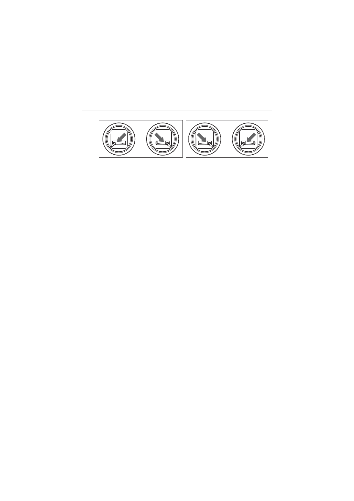
Figure 4-3 Motor Start-up or Shut-down
4. Release the sticks gently and simultaneously after the
motors have started spinning for 2 seconds.
5. Command the aircraft to take off. There are 2 methods
available:
A. Push the Throttle upward to take off the aircraft
manually.
B. Press and hold the Take-off button on the remote
controller for 2 seconds. The remote controller
makes a brief beep sound when the take-off
command is sent successfully.
Once the command is sent, the aircraft ascends
automatically and starts hovering when it reaches
the height of 2 meters.
4.3.2 Flight Attitude Controls
The aircraft reacts to the control inputs of the command sticks
transmitted through the RF signals. The flight speed varies
according to the push strength applied when moving the sticks.
NOTE:
For beginners it is recommended to move the command
sticks lightly and slowly to keep the aircraft flying in a controllable
speed. By applying the GPS mode, the aircraft self-positioning
capability is enabled, which allows more stable and safer flight
maneuvers.
44
Page 51

The 4 primary flight controls include:
A. Throttle
– commands the aircraft to ascend by pushing the
stick upward, and descend by pushing it downward.
:NXUZZRK[V
:NXUZZRKJU]T
)ROSH
*KYIKTJ
Figure 4-4 Throttle Control – Aircraft Left Side View
B. Rudder
– commands the aircraft to yaw left or right by
pushing the Rudder left or right.
Rudder right
Nose Yaws Right
45
Page 52

Rudder left
Nose Yaws Left
Figure 4-5 Rudder Control- Aircraft Top View
C. Elevator
– commands the aircraft to pitch up and down to
move forward or backward by pushing the Elevator upward
or downward.
Elevator down
Forward
Elevator up
Backward
Figure 4-6 Elevator Control – Aircraft Left Side View
46
Page 53

D. Aileron
– commands the aircraft to roll left or right by
pushing the Aileron left or right.
Aileron left
Aileron right
Figure 4-7 Aileron Control – Front View
4.3.3 Landing and Motor Shut-down
left
right
The aircraft may be landed manually, automatically, or passively
depending on different circumstances.
IMPORTANT:
The aircraft must be landed gently on a flat surface
to avoid damage.
z
Manual landing
Pilots may manually land the aircraft whenever and wherever they
choose and regard as safe by controlling the command sticks on
the remote controller.
47
Page 54

¾
To manually land the aircraft and shut down the motors
1. Maneuver the aircraft to the desired position for landing.
2. Release the command sticks when the aircraft reaches
the target position to let it hover.
3. Push the Throttle down slightly and gently to land the
aircraft.
4. When the aircraft has properly landed, operate with one
of the command methods below to shut off the motors:
A. Push the Throttle to the bottom position and hold
for 3 seconds, until the 4 motors stop spinning.
This simple method is recommended for
beginners.
B. Push and hold both the Command Sticks to their
bottom corners simultaneously, either toe-in or
toe-out, for a few seconds to stop the motors
(
Figure 4-3
).
5. Release the stick(s) gently and simultaneously after the
motors have stopped spinning.
z
Automatic landing
The Landing Button on the remote controller allows pilots to land
the aircraft automatically from where it is hovering (i.e. land onsite),
with one single click, without worries of controlling the flight
attitudes.
¾
To auto land the aircraft using the Landing Button
1. Maneuver the aircraft to the desired position for landing.
2. Release the command sticks when the aircraft reaches
the target position to let it hover.
3. Press and hold the Landing Button for 3 seconds until a
beep sound is heard.
4. Wait about 3 seconds and the aircraft will start to
descend and land automatically.
48
Page 55

z
Landing due to low battery
Generally it is recommended to land the aircraft immediately when
the battery level reaches 20% or lower, this will be indicated by the
indicator lights on both the aircraft and the remote controller.
A. The rear LEDs on the aircraft will show quick flashing red
lights.
B. The Aircraft Battery Indicator on the remote controller will
show yellow light.
z
Passive landing due to low battery
The aircraft will be forced to land automatically on wherever it is
hovering when the battery level reaches 10% or lower to avoid
accidents and damages.
z
Passive landing when Failsafe is activated
When the Failsafe function is activated, the aircraft will perform Go
Home (if GPS is available) or Onsite Landing (if GPS is not
available) to avoid accidents and damages.
4.3.4 Operations of Smart Flight Features
The X-Star Smart Flight System supports 3 major smart features:
z
Intelligent Orientation Control
To activate the IOC function during flight, toggle the Smart Control
Switch on the top left of the remote controller to the middle
position.
This feature has 2 control modes: Home Lock and Course Lock.
The Home Lock mode works in GPS mode only, while the Course
Lock mode works in both GPS and ATTI modes.
49
Page 56

Descriptions of the IOC modes:
Home Lock
- configures the aircraft to fly in the direction relative
to the home point, instead of its nose and tail. In this mode, the
Elevator will always move the aircraft on a line towards or away
from the initial take-off location, and the Aileron will make it move
right or left perpendicular to that line.
Course Lock
– also known as “Carefree Orientation” mode. In
this mode, all control directions are based on the initial orientation
of the aircraft, regardless of its current nose direction. This mode
can be used to keep the aircraft staying on track even if it is being
rotated.
In addition, Course Lock mode works regardless of distance from
the starting point, while Home Lock mode requires the aircraft to
be at least 10 meters away from home point. If the aircraft is
getting closer within 10 meters boundary from home point, Home
Lock mode will be automatically switched to Course Lock mode.
NOTE:
The flying direction is relative to the starting point but not
the location of the pilot. Home Lock mode works in GPS mode
only while Course Lock mode works in both GPS and ATTI
modes.
z
Go Home
The Go Home function only works in GPS mode. To manually
activate the Go Home function using the remote controller, toggle
the Smart Control Switch to the down position.
When the Go Home command has been successfully received,
the aircraft automatically maneuvers itself to return and land on
the prescribed home point with the shortest path.
When the Go Home procedure is activated, the remote controller
control will be disabled temporarily while the aircraft returns to the
home point. The Remote Controller control will be regained when
the aircraft starts to descend allowing the pilots to adjust the
aircraft attitude for a safe landing.
50
Page 57

NOTE:
For safety reasons, if the aircraft is hovering at the altitude
lower than 30 meters when the Go Home function is activated, it
will ascend to the 30-meter altitude before starting to return.
To manually regain control of the aircraft during the activated Go
Home procedure, take one of the methods below:
A. When Go Home is activated manually
Toggle the Smart Control Switch from Go Home position to
the other positions to regain control.
B. When Go Home is activated by Failsafe
There are 2 ways to regain control:
1. Press and hold the Take-off button on the remote
controller for 3 seconds. A brief beep sound can be
heard when the command has been sent successfully.
Move the command sticks to control the aircraft; if the
aircraft reacts correspondingly, the communication is
recovered.
2. Push the Throttle upward to the position of 60% in range,
i.e. slightly above the middle point (
Figure 4-8
), and
hold for 2 seconds. In this case, the aircraft may fly
upward slightly when the remote controller control is
recovered.
100%
60%
0%
Figure 4-8 Push the Throttle Upward (60% in range)
51
Page 58

A home point is usually memorized by the system as the point
where the aircraft motors start up each time. The home point can
also be repositioned during flight.
¾
Reposition the home point during flight
1. Maneuver the aircraft to the desired home point.
2. Release the command sticks when the aircraft reaches
the target position to let it hover.
3. Press and hold the Take-off Button for 3 seconds until a
beep sound is heard.
4. Press the Take-off Button again within a 5-second
interval; hold the button until a beep sound is heard.
The rear LEDs of the aircraft will show quick flashing
green lights for 3 seconds indicating the reset is
successful.
z
Failsafe
The Failsafe function will be activated after 5 seconds when
communication between the aircraft and the remote controller is
lost. This function enables the aircraft to automatically take the
protection measure.
Go Home is set as the priority protection measure when Failsafe is
activated.
In the case when GPS is available at the time Failsafe is activated,
the aircraft will start the Go Home procedure automatically.
In the case when GPS is not available (i.e. received GPS satellite
signals are less than 6) when Failsafe is activated, the aircraft will
hover for a 10 seconds interval. If GPS becomes available during
this interval, the aircraft will start the Go Home procedure,
otherwise the aircraft will land onsite.
52
Page 59

4.4 X-Star Mobile App Operations
The X-Star Mobile Application is a fully-featured program with 4
essential functions. It configures your mobile to perform as the central
monitor for remote piloting control, aerial shooting and recording, and
helps to tune the aircraft parameters to achieve refined and smooth
flight performance.
The 4 essential control functions are:
A. Camera Remote Control
– performs capturing, recording and set
camera settings through wireless control
B. Flight Data Display
z
Flight
z
Gimbal
z
Remote Controller
z
IMU Modules
z
Aircraft Battery
C. Ground Station Navigation
- displays parameters of:
– programs GPS waypoint navigation
missions, and set waypoint altitude, hover time and overall speed
D. Configuration Function
– performs parameter configuration for
the flight control system, gimbal system and remote controller
4.4.1 X-Star Mobile App Main Menu
Before first flight, make sure your mobile device is properly
connected to the X-Star WiFi network. When connection is
successful, the SSID of the WiFi network alongside with a green
tick icon will be displayed on the header of the Main Menu as
below.
53
Page 60

Figure 4-9 X-Star Mobile App Main Menu
The application buttons on the Main Menu are listed and
described in the table below:
Table 4-1 Application Buttons
Name Button Description
Allows data synchronization for
Camera
image display and camera pairing for
FPV or non-FPV navigation
Allows to locate the aircraft, and
Ground Station
perform waypoint navigation and
flight settings
Allows to perform parameter
Configuration
configuration and firmware upgrades
for the flight, gimbal and remote
control systems
Settings
Allows users to set various control
settings of the application
54
Page 61

4.4.2 Camera Operations
The Camera function works as a flight monitor that synchronizes
the screen display with the onboard camera, allowing users to
perform various camera operations and configurations for aerial
photo-and-video shooting. To enter the Camera Operation screen
(Figure 4-10), tap the
Camera
button on the Main Menu.
Figure 4-10
Camera Operation Screen
1. Pitch Control Panel
2. Status Information Bar
3. Camera Operation Panel
4. Ground Station Split Screen
z
Pitch Control Panel
The Pitch Control Panel consists of 3 control buttons, the
functions of which are described respectively from top to
bottom as follows:
1)
Back
– returns to X-Star Mobile App Main Menu
2)
Mode Switch
– switches between Normal Mode and
Physical Control Mode
55
Page 62

Normal Mode
In this mode, the camera pitch movement is controlled
by the pitch scroll bar. Scroll it up to tilt the camera
upwards or down to tilt the camera downwards.
Physical Control Mode
In this mode, the camera pitch angle simulates with the
motions of the mobile device. Tilt the mobile device
forward to pitch the camera down or backward to pitch
the camera up.
3)
Pitch Scroll Bar
– scrolls up or down to control the
camera pitch movement (Normal mode only)
z
Status Information Bar
The Status Information Bar on the top of the Camera
Operation Screen consists of 8 items. The features of each
item are described respectively from left to right as follows:
1)
Pitch Angle –
indicates the camera pitch angle
Flight Altitude –
2)
Flight Speed –
3)
Primary Flight Display –
4)
indicates planned flight height
indicates the current flying speed
indicates primary flight
information including the flight attitude (pitch and roll),
aircraft orientation, and approximate location
WiFi Indicator –
5)
Battery Level –
6)
Micro-SD Card –
7)
indicates the intensity of WiFi signal
displays current aircraft battery level
indicates the status of the Micro-SD
Card
The icon will be highlighted when a valid Micro-SD Card
is properly inserted. The number beside the icon shows
the remaining photo number.
8)
GPS –
displays the number of satellite signals received
56
Page 63
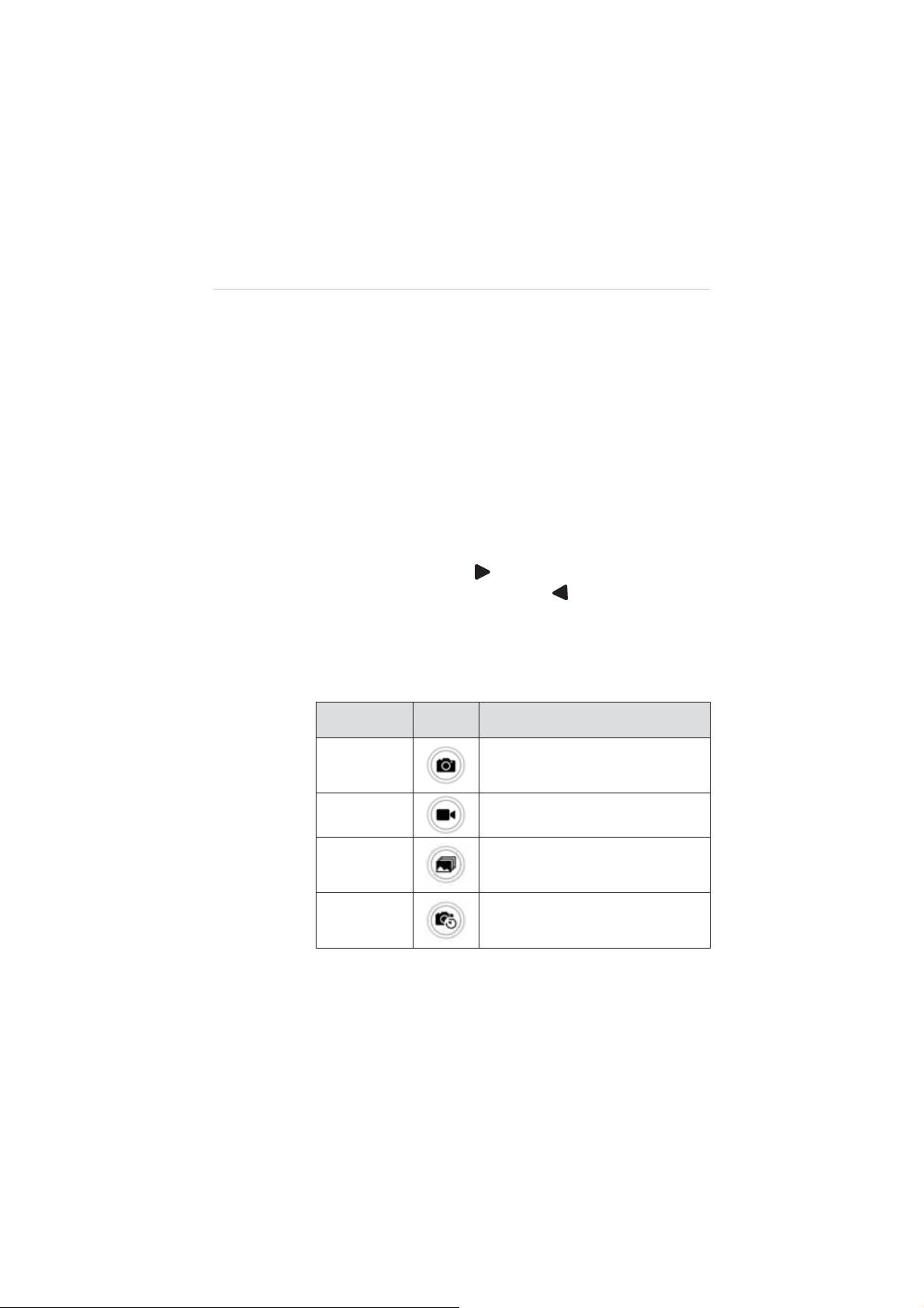
z
Camera Operation Panel
The Camera Operation Panel includes 5 items, the functions
of which are described respectively from top to bottom as
follows:
1)
Camera Settings
2)
Camera Mode
– opens the camera settings menu
– allows choosing different camera
modes, including single capture, burst mode, timed
capture and video shooting
3)
Shooting Button
– displays the current camera mode,
tapping which allows to execute the selected camera
mode action
Hide/Display
4)
– tap to hide the flight information bar
and the pitch control panel; tap to show them again
The table below lists and describes the functions of the
4 camera modes.
Table 4-2
Camera Mode Buttons
Mode Button Description
Single
Capture
Video
Burst
Time Lapse
Captures a single photo
Records video
Captures up to 10 photos in one
second
Captures a series of Photos at preset
intervals
57
Page 64

Camera Settings
By tapping the
Settings
button, the Settings Panel will be
displayed (Figure 4-11), which allows you to adjust camera
configuration settings.
Figure 4-11
Camera Settings Panel
The functions of each setting option are described in the
table below:
Table 4-3
General Camera Settings
Settings Button Options
Resolution
Frame Rate
FPS
1080P (16:9) (default); 960P (4:3);
720P (16:9); WVGA (16:9)
24, 30, 48, 60, 120, 240 fps (NTSC)
*PAL: 50 fps.
Time Lapse
Time
Stamp
0.5, 1, 2 sec; 5 sec (default),
10, 30, 60 sec
OFF (default); Date; Time; Date/Time
58
Page 65

Settings Button Options
TV System
Format ɰ;
Reset ɰ;
NOTE:
When you select Format in camera settings, the SD
PAL; NTSC (default)
(default)
(default)
card will be formatted. Make sure to create a back-up copy of
the SD card files.
When you select TV system to view a TV/HDTV, select
NTSC for North American televisions; for those outside of
North America, select PAL in most cases.
¾
To format a Micro-SD card:
1. Tap the
Camera Settings
button on the right side of
the screen to open the Settings Panel.
2. Tap
Format
button and a prompt will appear to
remind you that all data in the Micro-SD card will be
deleted if you proceed with this action.
3. Tap
YES
to complete formatting.
4. Reboot the camera when completed.
IMPORTANT:
Do not shut down the camera, or remove the
battery or Micro-SD card during the procedure.
After the above settings have been completed, you can
proceed with photo shooting or video recording.
¾
To take a photo:
1. Tap the
Camera Mode
button to select a desired
shooting method.
59
Page 66

Single Capture
: press
single photo
Burst Mode
: press
continuous capture
Time Lapse
: press
Shooting
timed capture, and press again to stop
2. Tap the
Shooting
button to run the selected camera
mode action.
¾
To record a video:
1. Tap the
Camera Mode
mode.
2. Tap the
Shooting
button to start recording: a red dot
will flash to indicate the recording is in progress and
a time code will appear in the upper right corner of
the preview screen.
3. Press the
¾
To view the saved photos or videos:
1. Press the
Shooting
Back
button on Pitch Control Panel to
button again to stop recording.
return to the main menu.
2. Tap the
Album
icon to view the saved photos or
recorded videos.
Shooting
Shooting
button once for a
button once for
button once to begin a
button and select the
Video
z
Ground Station Split Screen
The Ground Station Split Screen, located on the lower right
corner of the screen, allows the pilot to view the current
Ground Station operation during camera filming. Tapping the
Split Screen allows users to quickly switch to the Ground
Station operation screen.
60
Page 67

4.4.3 Ground Station Operations
The Ground Station function allows you to create flight plans by
placing waypoints, setting waypoint altitude, hover time and
overall speed, etc. To perform this function, tap the
Station
(Gmap or Amap) to initiate the program.
icon on the Main Menu, and select a desired map type
Ground
NOTE:
Figure 4-12
Make sure your mobile device is connected to the internet
Ground Station Operation Screen
when using this function for the first time to allow auto installing of
the maps.
1. Control Panel
2. Status Information Bar
3. Functional Buttons
4. Camera Split Screen
z
Control Panel
The Control Panel contains a number of buttons that allow
you to create flight plans, execute flight missions and
command the aircraft home. The table below provides a brief
description of the Control Panel buttons:
61
Page 68

Table 4-4
Control Panel Buttons
Name Button Description
Back
Returns to X-Star Mobile App Main
Menu
Waypoints
Start
Pause
Go Home
Landing
z
Status Information Bar
Opens the Waypoint Control Panel
Uploads the flight mission
Suspends execution of the flight
mission
Aborts the flight mission and
commands the aircraft home
Lands the aircraft
The Status Information Bar on the top of the main sections of
the screen displays the following items from left to right:
Flight Mode –
1)
Flight Altitude –
2)
Current Aircraft Distance –
3)
indicates the current flight mode
indicates planned flight height
indicates the distance
between the current aircraft position and the home point
Primary Flight Display –
4)
indicates various flight
information including the flight attitude (pitch and roll)
characteristics, orientation, and approximate location
info
5)
Flight Speed –
Wi-Fi Signal –
6)
7)
Battery Level –
GPS –
8)
displays number of satellite signals received
indicates the current flying speed
indicates the intensity of Wi-Fi signal
displays current battery level
62
Page 69

z
Functional Buttons
The Functional buttons are vertically aligned on the right side
of the operation screen. They are mainly used for controlling
flight speed, calibrating the compass, selecting map view and
locating the home point. Detailed descriptions of the
Functional Buttons are listed in the following table:
Table 4-5
Functional Buttons
Name Button Description
Speed
Compass
Map View
Sets the desired level flight speed: high
(8m/s), medium (5m/s) or low (2m/s).
Initiates the compass calibration
procedure.
Allows choosing a desired map view:
Normal, Hybrid or Satellite view.
Locates the current home point retrieved
from X-Star system on the map;
Locator
When aircraft GPS data is not available,
it will locate the current mobile position
on the map.
NOTE:
For safety concerns, there are only 3 gears of level flight
speed under auto mode: high speed (8m/s), medium speed (5m/s)
and low speed (2m/s).
z
Main Section
The Main Section, which occupies the center area of the
screen, displays the map and the current location of the
aircraft. In addition, there is a circle on the Main Section,
within which defines the
Safety Zone
. The aircraft can fly in
this area safely and legally.
63
Page 70
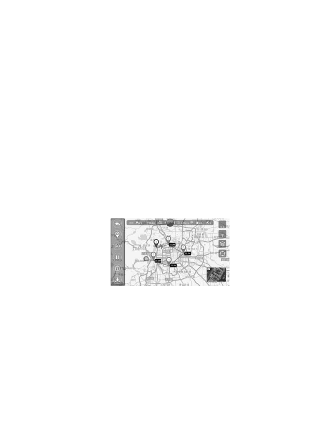
¾
To view the map on Main Section:
1. Tap the
Map View
button to choose among the
Normal, Hybrid or Satellite view.
2. Use two fingers to zoom in or zoom out the map.
3. Tap to move the map to view different areas.
z
Camera Split Screen
The Camera Thumbnail, located on the lower right corner of
the screen, allows the pilot to view the current camera filming
during Ground Station operation. Tapping the thumbnail
allows users to quickly switch to the camera operation
screen.
z
Waypoint Operations
Tapping the
launches the
Waypoints
button on the Control Panel opens
Waypoint Operation Panel
Figure 4-13
Waypoint Operation Panel
(Figure 4-13).
The Waypoint Operation Panel features the key functions of
the Ground Station, which allows you to set flight plans by
placing waypoints, defining flight altitude and hover time, etc.
The table below provides brief functional descriptions of the
Waypoint Operation Buttons:
64
Page 71

Table 4-6
Waypoint Operation Buttons
Name Button Description
Back
Exits the waypoint operation mode.
Adds a waypoint. The total number of
Add
Waypoints
waypoints should not exceed 20.
Waypoints cannot be added beyond
500m from the home point or outside
of the Safety Zone.
Draw
Waypoints
Remove
Waypoints
Move
Waypoints
Delete
Waypoints
Safety
Zone
NOTE:
N/A
To optimize video transmission quality, the aircraft is
Creates the flight route by sliding
through the map.
Removes the selected waypoint one
by one.
Moves the waypoint position one at a
time.
Deletes all waypoints.
Refers to the area within the circle.
The aircraft can fly in this area safely
and legally.
restricted to operate within a 500m-radius area from the
Home Point.
¾
To move the waypoints:
1. Tap the
Move Waypoints
button.
2. Tap on the specific waypoint, and drag it to a new
location.
3. Tap the
Move Waypoints
button again to confirm
the change.
65
Page 72

¾
To edit the waypoints:
1. Tap the desired waypoint number at the bottom of
the screen.
2. Adjust the waypoint altitude and hover time as
demanded.
3. Tap
¾
To start the flight mission:
1. Tap the
OK
to complete the waypoint setting.
Back
button to return to the Ground Station
Control Panel after completing the waypoint flight
plan setting.
GO
2. Tap
on the Control Panel to start the flight
mission.
¾
To terminate the waypoint mission:
There are two ways to terminate the waypoint mission:
1) Regain control of the aircraft by pushing the Flight
Mode Switch on the remote controller to
position. The aircraft will abort the mission and
respond to the navigation by the remote controller.
ATTI
2) Tap the
Go Home
button to activate the Go Home
procedure. The aircraft will terminate the mission
and return to the home point and land automatically.
¾
To land the aircraft:
When the flight mission has been completed, the
aircraft will return to the home point (i.e. take-off point)
automatically and hover.
There are 2 ways to land the aircraft:
1) Regain control of the aircraft using the remote
controller to land the aircraft manually or by using
the 1-click
2) Tap the
Landing
Landing
button
button on the Ground Station
Control Panel.
66
Page 73

4.4.4 Configuration Operations
The Configuration program is designed to configure and upgrade
the Smart Flight System and the Remote Controller. To optimize
the X-Star system performance for accurate and stable flight
maneuvering, it is recommended to perform configurations and
firmware upgrades on a regular basis, either through PC Aid or
X-Star Mobile App.
z
Flight Limits
Figure 4-14
Configuration Operation Screen
All unmanned aerial vehicle (UAV) pilots should comply with
all regulations from ICAO (International Civil Aviation
Organization) and national rules of the air in their own state.
For safety concerns, it is required to set up the flight limits to
ensure safe and legal operation of this product. The flight
limits settings include flight height, distance limits and Flight
Restricted Areas.
To set the flight limits, click the
Flight Limits
icon and the
screen below will be displayed:
67
Page 74

Figure 4-15
Flight Limits Setting Screen
You can set the maximum flight height and distance to
protect the aircraft from losing signal or being out of control.
When these limits are determined, the aircraft cannot fly
outside the preset limit boundaries under GPS mode. In
non-GPS mode, the aircraft is only restricted to the preset
height limit. For distance limit under non-GPS mode, it may
be various depending on the regulations and laws in different
areas and countries.
NOTE:
Under GPS mode, the maximum flight height must be
within 800 meters and flight distance must be within 1000
meters.
z
Gimbal
The Gimbal function is designed to perform Gimbal
parameters tuning such as sensitivity (roll, pitch and yaw)
and control speed, and to activate or deactivate FPV mode.
Tap the Gimbal icon, and the screen is displayed as below:
68
Page 75

Angle Limits
1)
Figure 4-16
Gimbal Control Screen
A. Horizontal Limit – sets the maximum angle on
horizontal axis
B. Vertical Limit – sets the maximum angle on vertical
axis
Control Sensitivity
2)
- adjusts the speed of camera pitch
movement
Mode Switch
3)
A. Non-FPV Mode –enables stabilized camera tilting
control
B. FPV Mode
–synchronizes the camera gimbal
movement with the aircraft
z
Flight Parameters
The Flight Parameters option is used to tune the systemic
parameters of the aircraft, including level flight speed,
descent speed, ascent speed and yaw rate, so as to achieve
safe and smooth flight maneuvers. Due to the highly
stabilized control system, the level speed, descent speed,
ascent speed and yaw rate can be adjusted within the
following ranges:
69
Page 76

Speed Range
Level Flight Speed 2m/s – 12m/s
Descent Speed 1m/s – 3m/s
Ascent Speed 1m/s – 6m/s
Yaw R at e 60q/s - 360 q/s
z
Remote Controller
The Remote Controller function enables the pilots to choose
preferred transmitter modes, calibrate command sticks and
testify if the Smart Control Switch and the Flight Mode Switch
work properly.
Tap the
Remote Controller
be displayed.
Figure 4-17
icon, and the screen below will
Remote Controller Screen
70
Page 77

The Remote Controller configuration screen consists of 3
sections.
1) Transmitter Modes Section
There are 3 transmitter modes: Mode 1, Mode 2, and
Mode 3. Each mode indicates how the movement of
command sticks controls the actions of the aircraft
correspondingly. Below are the illustrations of Mode 1,
Mode 2, and Mode 3:
Figure 4-18 Mode 1, 2 and 3
71
Page 78

The table below describes the respective aircraft
movements reacting to the movements of the command
sticks.
Table 4-7
Controls of the Command Sticks
Command Stick Movement Aircraft Movement
Throttle Up/Down Ascend/Descend
Rudder Left/Right Yaw Left/Right
Elevator Up/Down Forward/Backward
Aileron Left/Right Left/Right
2) Command Sticks Calibration
There are 4 channels in total for command sticks
calibration. They are A, E, T and R channels,
representing Aileron, Elevator, Throttle and Rudder
respectively. Before calibration, make sure your
desired transmitter mode has been selected.
¾
To calibrate the command sticks:
1. Turn on the remote controller and then the aircraft.
2. Connect your mobile device to the X-Star Wi-Fi
Network.
3. Launch the X-Star App on your mobile device.
4. Tap the
5. Tap the
Configuration
icon on the main menu.
Remote Controller
option.
6. Select your preferred transmitter mode and
familiarize yourself with the controls of the sticks.
7. Rotate the sticks in a circular pattern by their
maximum ranges several times and then back to the
middle position. You can do both sticks at a time or
one at a time.
72
Page 79

8. Tap
Finish
on the top right side to complete the
calibration. If all scale icons (A, E, T and R) fall in the
middle position, the remote controller is ready for
use.
3) Switch and Button Test
The Switch and button Test section allows users to test
the 2 switches on the front top of the remote controller
and 2 buttons at the bottom of the remote controller.
The upper switch group allows testing of the Smart
Control Switch which includes Normal, IOC and Go
Home modes.
The lower switch group allows testing of the Flight Mode
Switch which includes GPS, ATTI and ATTI modes.
The bottom two buttons allows testing of the 1-click
Take-off and Landing buttons.
When pushing the switch on the remote controller to a
specific position or press the specific button, the
corresponding mode will be highlighted accordingly.
Test both switches and buttons in each of their positions
successively.
Figure 4-19
Switch and Button Test – in Normal Pos.
73
Page 80

z
Failsafe
The Failsafe mode is set to enable the aircraft to take default
emergency protection procedure when communication with
the remote controller is lost, to prevent damage or injury. Go
Home is set as the priority protection measure when Failsafe
is activated.
When the Go Home procedure initiates, the aircraft’s nose
will be oriented towards Home Point. If the aircraft’s altitude
is lower than 30 meters, it will ascend to 30 meters height to
reduce risks of crashing or damages. If the aircraft altitude is
higher than 30 meters, then the aircraft will remain at its
height level, and returns to the home point with the shortest
flight route.
To view the demonstrations of the Failsafe procedure, tap the
Failsafe icon and the screen as shown below will be
displayed.
Figure 4-20
Failsafe Screen
There are several occasions that may cause the loss of the
remote controller signal:
A. The controller has been turned off
B. The aircraft has flown out of the distance limit
C. The signal between the aircraft and the remote controller
has been blocked or interfered
74
Page 81

z
Battery
The Battery function allows you to view the current status and
general information of the aircraft battery, and check the Low
Battery Protection settings. There are 2 levels of protection
measures for the inflight low battery concerns. Tap the
Battery
icon to enter the battery screen as below:
Figure 4-21
Battery Screen
The displayed battery information includes the following
items:
Current Status
1)
– displays voltage and current values of
the aircraft battery
General Information
2)
– displays general aircraft battery
information
Second Level Protection
3)
– activated when the battery
level reaches 20%, which by default triggers the rear
LEDs on the aircraft to quick flash in red lights. Users
can also activate/deactivate Go Home measure for this
protection setting
75
Page 82

4)
First Level Protection
– activated when the battery
level drops below 10% that forces the aircraft to
immediately land onsite
It is highly recommended to activate the Go Home procedure
or manually command the aircraft to return when the low
battery alarm is triggered (i.e. when the rear LEDs of the
aircraft show with quick flashing red lights).
z
IOC (Intelligent Orientation Control)
Intelligent Orientation Control (IOC) is a smart feature that
helps the pilot to navigate the aircraft without worrying about
its nose direction. This is very helpful for new pilots to regain
control of the aircraft orientation in case that the aircraft flies
too far away from the home point or when its orientation is
uncertain.
The IOC feature includes 2 modes:
1) Home Lock (HL) Mode
2) Course Lock (CL) Mode
See detailed descriptions of the IOC modes at 4.3.4
Operations of Smart Flight Features on page 49.
Tap the
IOC
icon on the main menu, and the IOC screen is
displayed (Figure 4-22).
76
Page 83

Figure 4-22
IOC Screen
NOTE:
The flying direction is relative to the starting point but
not the location of the pilot. Home Lock mode works in GPS
mode only while Course Lock mode works in both GPS and
ATTI modes.
z
View Status
Tapping
View Status
information screen, which presents an overview list of the
configuration status of the X-Star system.
4.4.5 Settings Operations
The
Settings
pilot to adjust 3 categories of items displayed on the Settings
menu, including camera settings, flight control and gimbal settings
and general settings.
icon on X-Star Mobile App Main Menu allows the
from the main menu displays an
77
Page 84

z
Camera Settings
1)
Toolbar Auto Hide
disable auto hide of the operation panels
2)
When Communication Lost
operation mode in case when communication is lost
3)
Preview Quality
– tap to select the resolution and
frame rate
z
Flight Control and Gimbal Settings
1)
Parameter Unit
– tap to select a measurement unit:
English or Metric
Ground Station
2)
– slide the button to enable or disable
the ground station feature
Compass Calibration
3)
calibration
Low Battery Auto Return
4)
or disable the auto return function for low battery
protection
5)
FPV Mode
– slide the button to activate or deactivate
the FPV mode
z
General Settings
1)
Low Battery Protection
disable the Low Battery Protection function
2)
Tips
– tap to enable tip display during operation
3)
Pairing
– displays the SSID and MAC information of the
paired aircraft, and allows pairing to other aircraft by
entering new SSID and MAC address
4)
Rename SSID
– tap to rename the SSID of the X-Star
WiFi Network
Find My X-Star
5)
– locates the aircraft position according
to the last GPS signal retrieved before communication is
lost
78
– slide the button to enable or
– allows to set the camera
– tap to start compass
– slide the button to enable
– slide the button to enable or
Page 85

4.5 PC Aid Operations
The PC Aid Suite is specially developed for enhancing aircraft
capabilities and refining flight performance. This comprehensive
program allows users to perform pre and post flight configurations and
upgrade firmware for the X-Star aircraft, gimbal and remote controller
on the PC.
Launch the PC Aid program after installation is complete.
After logging in to your PC Aid account, a prompt screen will appear to
remind you to connect the aircraft or the remote controller to the
computer, if you haven’t done already. In this case, use the USB cable
supplied to connect the devices. The PC Aid operation screen will be
displayed when the connection is successful.
Figure 4-23
PC Aid Operation Screen
79
Page 86

The PC Aid Operation screen includes 3 main sections:
z
Menu Bar
The Menu Bar consists of 4 tags:
1) Flight Control System Settings
2) Gimbal Settings
3) Remote Controller Settings
4) Firmware Upgrades
Selecting each tag will navigate you to the corresponding
operation page.
z
Navigation Pane
The Navigation Pane displays all the items that are required
to be adjusted or calibrated for the flight system, gimbal and
remote controller before or after flight. The items may vary
according to the specific tag selected on the Menu Bar.
z
Main Screen
This section, which occupies a great part of the display area
on the PC Aid operating screen, shows various content
depending on the operation selected on the Menu Bar and
Navigation Pane.
Table 4-8
Functional Buttons under the Flight Tag
Name Button Description
Allows pilots to set limits for the flight
Flight Limits
height, distance and speed, and
displays the different categories of
flight restricted areas.
Examines and calibrates the
IMU Calibration
parameters of the gyroscope,
acceleration sensor, and compass to
ensure accurate flight controls.
80
Page 87

Name Button Description
Enables the aircraft to take automatic
Failsafe
failsafe measure when communication
with the remote controller is lost.
Displays the battery information, and
Battery
allows activating/deactivating the low
battery protection function.
Allows pilots to set the IOC mode for
IOC
easy aircraft navigation when its
orientation is uncertain.
View Status
Table 4-9
N/A
Functional Buttons under the Gimbal Tag
Displays current configuration status of
the X-Star system.
Name Button Description
Basic
Table 4-10
Functional Buttons under Remote Controller Tag
Adjusts and calibrates gimbal
parameters.
Name Button Description
Allows pilots to choose preferred
Remote
Controller
Remote Control Mode, calibrate
command sticks, and testify if the
control switches and sticks work
properly.
81
Page 88

Chapter 5 Maintenance and Service
To ensure optimum performance of the product, we advise that the
maintenance instructions in this section are read and followed carefully.
5.1Maintenance Instructions
The following shows how to maintain your devices, together with precautions
to take.
y
Keep the devices in dry conditions and within normal operating
temperatures.
y
Dry your hands before using the devices. The touch screen of the
camera may not work if it is moist, or if you tap it with wet hands.
y
Do not store the devices in humid, dusty or dirty areas.
y
Do not attempt to disassemble your devices.
y
Use a soft cloth with alcohol or a mild window cleaner to clean the touch
screen of the camera.
y
Do not use any abrasive cleansers, detergent or chemicals on the
camera.
y
Avoid dropping your devices, especially on a hard surface.
y
Use only authorized battery chargers and accessories. Any malfunction
or damage caused by the use of unauthorized battery charger and
accessories will void the limited warranty.
y
Ensure that the battery charger does not come in contact with
conductive objects.
82
Page 89

5.2Troubleshooting Checklist
This section helps users to detect possible causes to certain
problems occurred, and provide feasible solutions to handle
certain operation failures.
A.
When the aircraft indicates failure during self-check
LED lights flashing slowly in red and the buzzers beep all the time)
9
Check if the IMU is properly calibrated through the PC Aid or
X-Star Mobile App
9
Check if the remote controller parameters are properly
calibrated
B.
When the aircraft motors fail to start up
9
Check if the remote controller and the aircraft are properly
paired
9
Check if the remote controller parameters are properly
calibrated
C.
When take-off fails after motors are initiated
9
Check if the Smart Control Switch is in the Normal position
(flipped up)
(with 4
9
Make sure the Flight Mode Switch is not in the GPS position
when the GPS satellite signals are less than 6
9
Check if the battery level is high enough
9
Check if the aircraft is in no-fly zone
9
Check if the aircraft is placed on a flat ground
D.
When the aircraft’s flight time reduces
9
Make sure the battery is in a warm environment before use
83
Page 90

E.
When pairing up, the aircraft does not respond to the remote
controller
9
Make sure there is no large metal object, wireless source or
other remote controller around
F.
If the Wi-Fi connection fails all the time
9
Make sure to be free from all magnetic or signal interferences
G.
If the camera is powered off during video recording
9
Keep the MicroSD card inside the camera. Restart the
camera and wait until the video files are recovered (partial
data may be lost)
H.
If acquisition of the SSID fails
9
Check if both the aircraft and the remote controller are
powered on
9
Make sure WiFi is enabled on both the mobile device and the
Remote Controller
I.
If the aircraft is out of sight and the Wi-Fi connection is lost
9
Enable Go Home procedure to let it return or activate IOC
procedure to manually navigate it to return
J.
If the camera fails to be synchronized with the mobile device
9
Check if your mobile device supports synchronization of the
1080i60 video files
9
If the video size is too large, it cannot be synchronized to the
mobile device
9
Check if your mobile device is connected to X-Star WiFi
Network
K.
If sharing of files failed
9
Check if your mobile device is connected to the internet
84
Page 91

L.
If the X-Star mobile app is accidentally closed when the
aircraft is in Ground Station mode
9
If the app is closed when the flight mission is under execution,
the aircraft will continue to finish
9
If the app is closed when the flight mission is being
suspended, and failed to reconnect with the aircraft within 1
minute, Go Home procedure will be automatically activated
9
Regain manual control of the aircraft using the remote
controller
5.3Service Procedures
This section introduces information for technical support, repair service,
and application for replacement or optional parts.
Technical Support
If you have any question or problem on product operations, please:
z
Call 0086-755-86147779 (China).
z
Contact local distributers or agents.
z
Visit our website http://www.maxaero.com.
Repair Service
If it becomes necessary to return your device for repair, please
download the repair service form from www.maxaero.com
form. The following information must be included:
A.
Contact name
B.
Return address
C.
Telephone number
D.
Product name
85
, and fill in the
Page 92

E.
Complete description of the problem
F.
Proof-of-purchase for warranty repairs
G.
Preferred method of payment for non-warranty repairs
NOTE:
For non-warranty repairs, payment can be made via Visa,
Master Card, or with approved credit.
Send the device to your local agent, or to the following address:
6th-10th Floor, Building B1, Zhiyuan, Xueyuan Road, Xili, Nanshan,
Shenzhen, 518055, China
Other Services
You can purchase the optional accessories directly from Maxaero’s
authorized tool suppliers, and/or your local distributors or agents.
Your purchase order should include the following information:
z
Contact information
z
Product or part name
z
Item description
z
Purchase quantity
86
Page 93

Chapter 6 Warranty
Autel Aerial Technology Co., Ltd. (the Company) warrants to the original
retail purchaser of this product, that should this product or any part thereof
during normal consumer usage and conditions be proven defective in
material or workmanship that results in product failure within the valid
warrant period from the date of delivery, such defect(s) will be repaired, or
replaced (with new or rebuilt parts) with Proof of Purchase, at the
Company’s option, without charge for parts or labor directly related to the
defect(s).
Please visit http://www.maxaero.com
warranted for the different parts of this product.
The Company shall not be liable for any incidental or consequential
damages arising from the use, misuse, or mounting of the device. Failure to
follow the safety instructions presented throughout the manual will void the
warranty of the product. Some states or countries do not allow limitations on
how long an implied warranty lasts, so the above limitation may not apply to
you.
for details of the limited periods
This warranty does not apply to:
a) Products subjected to abnormal use or conditions, accident,
mishandling, neglect, unauthorized alteration, misuse, improper
installation or repair or improper storage;
b) Products whose mechanical serial number or electronic serial number
has been removed, altered or defaced;
c) Damage from exposure to excessive temperatures or extreme
environmental conditions;
d) Damage resulting from connection to, or use of any accessory or other
product not approved or authorized by the Company;
e) Defects in appearance, cosmetic, decorative or structural items such as
framing and non-operative parts.
f) Products damaged from external causes such as fire, dirt, sand, battery
leakage, blown fuse, theft or improper usage of any electrical source.
87
Page 94

FCC Caution:
This equipment has been tested and found to comply with the limits for a Class B digital device,
pursuant to part 15 of the FCC Rules. These limits are designed to provide reasonable
protection against harmful interference in a residential installation. This equipment generates,
uses and can radiate radio frequency energy and, if not installed and used in accordance
with the instructions, may cause harmful interference to radio communications. However,
there is no guarantee that interference will not occur in a particular installation. If this
equipment does cause harmful interference to radio or television reception, which can be
determined by turning the equipment off and on, the user is encouraged to try to correct the
interference by one or more of the following measures:
—Reorient or relocate the receiving antenna.
—Increase the separation between the equipment and receiver.
—Connect the equipment into an outlet on a circuit different from that to which the receiver is
connected.
—Consult the dealer or an experienced radio/TV technician for help.
Page 95

FCC Caution:
Any Changes or modifications not expressly approved by the party responsible for
compliance could void the user's authority to operate the equipment.
This device complies with part 15 of the FCC Rules. Operation is subject to the following two
conditions:
(1) This device may not cause harmful interference, and (2) this device must accept any
interference received, including interference that may cause undesired operation.
This equipment complies with FCC radiation exposure limits set forth for an
uncontrolled environment.
This equipment should be installed and operated with minimum distance 20cm
between the radiator& your body.
This transmitter must not be co-located or operating in conjunction with any other antenna or
transmitter.
Note:This equipment has been tested and found to comply with the limits for a Class B digital
device, pursuant to part 15 of the FCC Rules. These limits are designed to provide
reasonable protection against harmful interference in a residential installation. This equipment
generates, uses and can radiate radio frequency energy and, if not installed and used in
accordance with the instructions, may cause harmful interference to radio communications.
However, there is no guarantee that interference will not occur in a particular inst allation. If this
equipment does cause harmful interference to radio or television reception, which can be
determined by turning the equipment off and on, the user is encouraged to try to correct the
interference by one or more of the following measures:
—Reorient or relocate the receiving antenna.
—Increase the separation between the equipment and receiver.
—Connect the equipment into an outlet on a circuit different from that to which the receiver is
connected.
—Consult the dealer or an experienced radio/TV technician for help.
 Loading...