

Page 1
Quick Reference Guide
APB112 SMART KEY SIMULATOR
Email: sales@autel.com
Web: www.autel.com
Page 2
Thank you for purchasing AUTEL tool. Manufactured to a
high standard, our tool will, if used according to these
instructions and properly maintained, give you years of
trouble-free performance.
Product Description
APB112 smart key simulator is designed to collect the
data sent from the ignition coil, aiming to identify the
ignition coil troubles and decode the data of the vehicle
key chip. It can also simulate the vehicle key chip.
Currently, it supports to simulate the 4D type chip and
more key chip types will be supported with subsequent
upgrades.
1
2
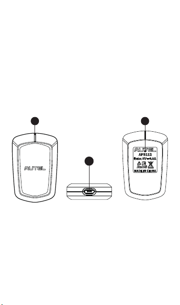
APB112 Smart Key Simulator
1. Status indicator---Indicates the current status (lights
solid blue - the power supply is working properly and in
default state; flashes green – the data interaction
status; flashes red - the status of upgrading; lights solid
red - the Boot status)
2. USB interface---provides power and data
communication
3. Product Information
3
Page 3

Getting Started
IMPORTANT: Before operating or maintaining this
unit, please read these instructions carefully, pay
extra attention to the safety warnings and
precautions. Use this unit correctly and properly.
Failure to do so may cause damage and/or personal
injury and will void the product warranty.
1. Connect the APB112 Smart Key Simulator to Autel
Diagnostic Device using the supplied USB cable.
2. After connection, the status indicator lights solid blue,
indicating that the APB112 Smart Key Simulator is
working properly and then automatically communicates
with the Diagnostic Device.
3. The APB112 Smart Key Simulator application is
automatically upgraded on Autel Diagnostic Device
according to the selected vehicle system function.
4. Place the Smart Key Simulator close to the ignition coil
for data collection, which is used for decoding the chip.
After decoding, the original car chip data can be
copied.
5. The emulator key chip can generate various types of
key chips with subsequent upgrades according to
requirements.
Precautions:
1. The APB112 Smart Key Simulator needs to be used
together with the Autel Diagnostic Device.
2. Do not disconnect the USB cable when use.
Connection Diagram
Page 4

Packing List
APB112 Smart Key Simulator
Quick Reference Guide
USB Cable
Warranty
Autel guarantees that the APB112 Smart Key Simulator is
free from material and manufacturing for a period of 12
months, whichever comes first. Autel will at its discretion
replace any merchandise during the warranty period. The
warranty shall be void if any of the following occurs:
1. Improper installation of the product;
2. Improper use;
3. Product damage due to collision, man-made damage
or natural disasters;
4. Exceed the product-specific use restrictions.
For service and support, please contact us.
http://pro.autel.com / www.autel.com / support@autel.com
0049 (0) 61032000522 (Europe) / (+507) 308-7566 (South
© Autel Intelligent Technology Corp., Ltd. All Rights Reserved.
0086-755-86147779 (China HQ) /
1-855-288-3587/1-855-AUTELUS (North America)
America) / 03 9480 2978 / +61 476293327 (Australia)
Page 5

FCC STATEMENT :
This device complies with Part 15 of the FCC Rules.
Operation is subject to the following two conditions:
(1)This device may not cause harmful interference, and
(2)This device must accept any interference received,
including interference that may cause undesired
Warning: Changes or modifications not expressly approved
by the party responsible for compliance could void the user's
authority to operate the equipment.
NOTE: This equipment has been tested and found to comply
with the limits for a Class B digital device, pursuant to Part 15
of the FCC Rules. These limits are designed to provide
reasonable protection against harmful interference in a
residential installation. This equipment generates uses and can
radiate radio frequency energy and, if not installed and used in
accordance with the instructions, may cause harmful
interference to radio communications. However, there is no
guarantee that interference will not occur in a particular
installation. If this equipment does cause harmful interference
to radio or television reception, which can be determined by
turning the equipment off and on, the user is encouraged to
try to correct the interference by one or more of the following
measures:
Reorient or relocate the receiving antenna.
Increase the separation between the equipment and
receiver.Connect the equipment into an outlet on a circuit
different from that to which the receiver is connected.
Consult the dealer or an experienced radio/TV technician for
help.
operation.
 Loading...