

Page 1

Trademarks
Autel®,MaxiSys®,MaxiDAS®, MaxiScan®, MaxiCheck®, MaxiRecorder®,
and MaxiCheck
registered in China, the United States and other countries. All other marks
are trademarks or registered trademarks of their respective holders.
®
are trademarks of Autel Intelligent Technology Corp., Ltd.,
Copyright Information
No part of this manual may be reproduced, stored in a retrieval system or
transmitted, in any form or by any means, electronic, mechanical,
photocopying, recording, or otherwise without the prior written permission
of Autel.
Disclaimer of Warranties and Limitation of Liabilities
All information, specifications and illustrations in this manual are based on
the latest information available at the time of printing.
Autel reserves the right to make changes at any time without notice. While
information of this manual has been carefully checked for accuracy, no
guarantee is given for the completeness and correctness of the contents,
including but not limited to the product specifications, functions, and
illustrations.
Autel will not be liable for any direct, special, incidental, indirect damages
or any economic consequential damages (including the loss of profits).
IMPORTANT
Before operating or maintaining this unit, please read this manual carefully,
paying extra attention to the safety warningsandprecautions.
For Services and Support
pro.autel.com
www.autel.com
1-855-288-3587/1-855-AUTELUS (North America)
0086-755-86147779 (China)
support@autel.com
For technical assistance in all other markets, please refer to Service and
Support section in this manual.
i
Page 2

Safety Information
For your own safety and the safety of others, and to prevent damage to the
device and vehicles upon which it is used, it is important that the safety
instructions presented throughout this manual be read and understood by
all persons operating or coming into contact with the device.
There are various procedures, techniques, tools, and parts for servicing
vehicles, as well as in the skilloftheperson doing the work. Because of the
vast number of test applications and variations in the products that can be
tested with this equipment, we cannot possibly anticipate or provide advice
or safety messages to cover every circumstance. It is the automotive
technician’s responsibility to be knowledgeable of the system being tested.
It is crucial to use proper service methods and test procedures. It is
essential to perform tests in an appropriate and acceptable manner that
does not endanger your safety, the safety of others in the work area, the
device being used, or the vehicle being tested.
Before using the device, always refer to and follow the safety messages
and applicable test procedures provided by the manufacturer of the vehicle
or equipment being tested. Use the device only as described in this manual.
Read, understand, and follow all safety messages and instructions in this
manual.
Safety Messages
Safety messages are provided to help prevent personal injury and
equipment damage. All safety messages are introduced by a signal word
indicating the hazard level.
DANGER
Indicates an imminently hazardous situation which, if not avoided, will
result in death or serious injury to the operator or to bystanders.
WARNING
Indicates a potentially hazardous situation which, if not avoided, could
result in death or serious injury to the operator or to bystanders.
ii
Page 3

Safety Instructions
The safety messages herein cover situations Autel is aware of. Autel
cannot know, evaluate or advise you as to all of the possible hazards. You
must be certain that any condition or service procedure encountered does
not jeopardize your personal safety.
DANGER
When an engine is operating, keep the service area WELL VENTILATED
or attach a building exhaust removal system to the engine exhaust system.
Engines produce carbon monoxide, an odorless, poisonous gas that
causes slower reaction time and can lead to serious personal injury or loss
of life.
SAFETY WARNINGS
Always perform automotive testing in a safe environment.
Wear safety eye protection that meets ANSI standards.
Keep clothing, hair, hands, tools, test equipment, etc. away from all
moving or hot engine parts.
Operate the vehicle in a well-ventilated work area, for exhaust gases
are poisonous.
Put the transmission in PARK (for automatic transmission) or
NEUTRAL (for manual transmission) and make sure the parking brake
is engaged.
Put blocks in front of the drive wheels and never leave the vehicle
unattended while testing.
Be extra cautious when working around the ignition coil, distributor cap,
ignition wires and spark plugs. These components create hazardous
voltages when the engine is running.
Keep a fire extinguisher suitable for gasoline, chemical, and electrical
fires nearby.
Do not connect or disconnect any test equipment while the ignition is
on or the engine is running.
Keep the test equipment dry, clean, free from oil, water or grease. Use
a mild detergent on a clean cloth to clean the outside of the equipment
as necessary.
iii
Page 4

Do not drive the vehicle and operate the test equipment at the same
time. Any distraction may cause an accident.
Refer to the service manual for the vehicle being serviced and adhere
to all diagnostic procedures and precautions. Failure to do so may
result in personal injury or damage to the test equipment.
To avoid damaging the test equipment or generating false data, make
sure the vehicle battery is fully charged and the connection to the
vehicle DLC is clean and secure.
Do not place the test equipment on the distributor of the vehicle.
Strong electro-magnetic interference can damage the equipment.
iv
Page 5

CONTENTS
SAFETY MESSAGES....................................... .................................... .........................II
SAFETY INSTRUCTIONS
1 USING THIS MANUAL
C
ONVENTIONS............................................................................................................1
Bold Text
...................................................................................................... .........
Notes and Important Messages
Hyperlink.......................................................................... .....................................2
Illustrations
...................................................................................................... .....
2 GENERAL INTRODUCTION
F
UNCTIONAL DESCRIPTION......................................................... ..............................3
TECHNICAL SPECIFICATIONS
IRELESS COMMUNICATION
W
POWER SOURCE..................................................................... ...................................5
3 GETTING STARTED
POWERING UP
...................................................................................................... ......
NAVIGATION BUTTONS..............................................................................................8
4EOBD
5 SERVICE
...................................................................................................... ....................
...................................................................................................... .............
O
IL RESET SERVICE................................. .................................... ...........................11
ELECTRONIC PARKING BRAKE (EPB) SERVICE
EPB Safety
...................................................................................................... ...
BMS.........................................................................................................................13
Register Battery Replacement
STEERING ANGLE SENSOR (SAS) SERVICE
DPF SERVICE.................................... .................................... ..................................15
TIRE PRESSURE MONITOR SYSTEM (TPMS) SERVICE
IMMO S
ERVICE
6HISTORY................................... ..................................................................... ...........18
...................................................................................................... .........................
7ME
.............................................................................................
..............................................................................................
.......................................................................
....................................................................................
.....................................................................................
.....................................................................................
.................................................................................................
...................................................
.......................................................................
.........................................................
.......................................
...................................................................................................... .
10
11
12
12
13
14
16
16
19
III
1
1
1
2
3
4
5
6
6
v
Page 6

EGISTER.................................................................................................................19
R
...................................................................................................... ................
LOG IN
EPAIR REPORTS
R
....................................................................................................
19
20
VCI CONNECTION.................................................. .................................... ..............21
APPS UNINSTALL
RDER MANAGEMENT
O
.....................................................................................................
.............................................................................................
21
22
VCI MANAGEMENT....................................... .................................... .......................22
DATA LOGGING
ETTINGS
S
..................................................................................................... ...
..................................................................................................... ............
22
23
Unit................................................... ...................................................................23
User Guide
About
U
SER MANUAL.........................................................................................................24
8 PRODUCT TROUBLESHOOTING
VEHICLE LINKING ERROR
...................................................................................................... ...
...................................................................................................... .............
.......................................................................
........................................................................................
23
24
25
25
9 COMPLIANCE INFORMATION............................................................... ............. 26
10 WARRANTY AND SERVICE
LIMITED ONE YEAR WARRANTY
...............................................................................
.............................................................................
28
28
This warranty does not apply to:....................................................................28
SERVICE AND SUPPORT
..........................................................................................
29
vi
Page 7

1
Using This Manual
This manual contains device usage instructions.
Some illustrations shown in this manual may contain modules and optional
equipment that are not included in your system. Contact your sales
representative for availability of other modules and optional tools or
accessories.
Conventions
The following conventions are used.
Bold Text
Bold text is used to highlight selectable items such as buttons and menu
options.
Example:
Tap OK.
Notes and Important Messages
Notes
A NOTE provides helpful information such as additional explanations, tips,
and comments.
Example:
NOTE
New batteries reach full capacity after approximately 3 to 5 charging and
discharging cycles.
1
Page 8

Important
IMPORTANT indicates a situation which, if not avoided, may result in
damage to the test equipment or vehicle.
Example:
IMPORTANT
Keep the cable away from heat, oil, sharp edges and moving parts.
Replace damaged cables immediately.
Hyperlink
Hyperlinks, or links, that take you to other related articles, procedures, and
illustrations are available in electronic documents. Blue italic text indicates
a selectable hyperlink and blue underlined text indicates a website link or
an email address link.
Illustrations
Illustrations used in this manual are samples, the actual testing screen may
vary for each vehicle being tested. Observe the menu titles and on-screen
instructions to make correct option selection.
2
Page 9
2
General Introduction
The wireless diagnostic interface MaxiAP AP200 is a small interface
adapter used to connect to a vehicle’s diagnostic connector (DLC) and
connect wirelessly with the iOS or Android devices for vehicle data
transmission, making your iOS or Android devices (hereinafter referred to
as device or devices) into a powerful diagnostic tool.
The MaxiAP AP200 package includes a Bluetooth (BT) OBDII connector
and a MaxiAP200 app. It is the perfect Do-It-Yourself tool for customers
looking for quick and easy OBDII as well as vehicle-specific diagnostic
functions. It is almost compatible with all European, Asian, and U.S.
international vehicle models.
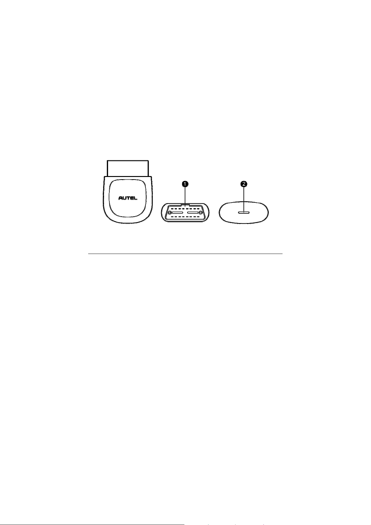
Figure 2- 1 Product View
Functional Description
1. Vehicle Data Connector (16-pin) – connects the MaxiAPAP200 to the
vehicle’s 16-pin DLC directly.
2. Power LED – indicates system status.
The power LED displays green, blue, red depending on power level and
operating state.
3
Page 10

A. Green
Lights solid green when the MaxiAP AP200 is plugged in and not
connected with the device.
B. Blue
Lights solid blue when the device is connected with the MaxiAP
AP200 via Bluetooth.
Flashes blue when the device is communicating with the MaxiAP
AP200, for example, when the device is reading Engine DTCs.
C. Red
Lights solid red when the MaxiAP AP200 is updating the firmware
or when the update failed.
NOTE
When the MaxiAP AP200 has lost connection from the device for more
than 10 minutes, the LED goes off and the AP200 enters power saving
standby mode. The power LED will light when reconnected.
Technical Specifications
Table 2- 1 Specifications
Item Description
Communications BT3.0 + BT4.0
Wireless Frequency 2.4 GHz
Input Voltage Range 9VDCto26VDC
Supply Current 100 mA@12 V
Sleep Mode Current 3mA@12V
Operating Temp. 0°C to 50°C
Storage Temp. -20°C to 70°C
4
Page 11

Dimensions (L * W *H)59.2 mm (2.33’’) * 48.5 mm (1.91’’) * 24.6 mm
(0.97’’)
Weight 35g (0.07 lb.)
Wireless Communication
The MaxiAP AP200 uses BT communication. It can transmit vehicle data to
your iOS or Android devices without a physical connection. The working
range for BT communication is about 33 feet (about 10 m). Signal lost due
to moving out of range will automatically be restored once the device is
brought within transmission range to the MaxiAP AP200 connector.
Power Source
The MaxiAP AP200 operates on 12-volt vehicle power that it receives
through the vehicle data connection port. The unit powers on whenever it is
connected to an OBDII/ EOBD compliant data link connector (DLC).
5
Page 12

3
Getting Started
NOTE
The images and illustrations depicted in this manual may differ from the
actual ones. The user interface for iOS and Android devices might be
slightly different.
Powering Up
1. Download & installation
Search for MaxiAP200 in APP Store or Google Play to download
and install the app to your device.
Or scan the QR code to download the MaxiAP200 app.
2. Register & login
Open the MaxiAP200 app and click Register near the top right.
Follow the on-screen instructions to complete the registration.
Log in with the registered email address and password.
NOTE
You can log i n with your registered Autel user ID if you already have one.
3. Plug the connector of the MaxiAP200 tool into the vehicle’s Data Link
Connector (DLC).
The vehicle’s DLC is generally located under the vehicle dash.
6
Page 13

4. Turn the ignition to Key On, Engine Off position.
The LED on AP200 illuminates solid green.
5. VCI Connection
Tap Me > VCI Connection or the VCI button near the top right of the
Home screen. Tap the Bluetooth name of the MaxiAP AP200 tool to
pair it with the device. The Bluetooth name starts with AP, followed by
the serial number of the tool.
Ensure the device’s Bluetooth is turned on.
When the device is successfully paired with the tool, you will hear
a beep sound and the LED on the tool illuminates solid blue.
Check if the communication status turns to VCI connected. Tap
Done near the top left to return to the Home screen.
NOTE
For IOS devices, pair the MaxiAP AP200 tool with the device via Settings >
Bluetooth and then go back to the app.
6. Bind VCI
Tap Me > VCI Management. Scan the QR code on the MaxiAP AP200
tool to put in the serial number. Check if the email information is
correct. Tap Bind to bind VCI.
7. Your MaxiAP200 app is now ready for use.
Tap Mall to purchase vehicle-specific software.
7
Page 14

Figure 3-1 Sample MaxiAP200 Job Menu
8. The table below briefly describes each of the applications in theAP200
system.
Table 3- 1 Applications
Button Name Description
Eobd Accesses EOBD/OBDII diagnostic functions.
Service Accesses 19 service functions.
History
Accesses diagnosis and service records with
vehicle information and DTCs included.
Navigation Buttons
Operations of the Navigation buttons at the bottom of the screen are
described in the table below:
8
Page 15

Table 3- 2 Navigation Buttons
Button Name Description
Home Returnsto the Home screen.
Mall Displays software programs available
Displays list of functions, including Repair
Me
Reports, VCI Connection, Uninstall Vehicle
Software, Order Management, VCI
Management, Settings and User Manual
9
Page 16

4
n
Eobd
This option provides EOBD/OBDII diagnostic functions for vehicles. read
and clear pending, stored and permanent codes for European, Asian, and
U.S. OBDII/EOBD compatible vehicles, 1996 and newer.
It can also read and clear enhanced codes for engine and transmission
systems of GM, Chrysler, and Ford vehicles. Autel provides regular
updates for this app that will expand vehicle coverage and access to
available modules.
Tap > to view the details of a specific DTC (Diagnostic Trouble Codes). At
the bottom of the DTC Details screen, you can also tap the Previous or
Next button to view the details of the previous or next DTC. Or tap the
snowflake button at the bottom middle of the screen to view the freeze
Figure 4- 1 Sample Eobd Funcion Scree
frame of the specific DTC, if available.
10
Page 17

5
Service
The Service section is specially designed to provide you with quick access
to the vehicle systems for various scheduled service and maintenance
performances. The typical service operation screen is a series of menu
driven executive commands. By following the on-screen instructions to
select appropriate execution options, enter correct values or data, and
perform necessary actions, the system will guide you through the complete
performance for various service operations.
The most commonly performed service functions include:
Oil Reset Service
EPB Service
BMS Service
SAS Service
DPF Service
TPMS Service
IMMO Service
After entering each special function, the displayed screen consists of two
applications: Diagnosis and Hot Functions.TheDiagnosis is for you to
read/clear data since this is necessary after some special functions. Hot
Functions consists of sub functions of the selected special function.
Oil Reset Service
This function allows you to perform reset for the Engine Oil Life system,
which calculates an optimal oil life change interval depending on the
vehicle driving conditions and climate. The Oil Life Reminder must be reset
every time the oil is changed, so the system can calculate when the next oil
change is required.
11
Page 18

IMPORTANT
Always reset the engine oil life to 100% after every oil change.
NOTE
All required work must be carried out before the service indicators are reset.
Failure to do so may result in incorrect service values and cause DTCs to
be stored by the relevant control module.
Electronic Parking Brake (EPB) Service
This function has a multitude of usages to maintain the electronic braking
system safely and effectively. The applications include deactivating and
activating the brake control system, assisting with brake fluid control,
opening and closing brake pads, and setting brakes after disc or pad
replacement, etc.
EPB Safety
It may be dangerous to perform Electronic Parking Brake (EPB) system
maintenance, so before you begin the service work, please keep these
rules i n mind.
Ensure that you are fully familiar with the braking system and its
operation before commencing any work.
The EPB control system may be required to be deactivated before
carrying out any maintenance/diagnostic work on the brake system.
This can be done from the tool menu.
Only carry out maintenance work when the vehicle is stationary and on
level ground.
Ensure that the EPB control system is reactivated after the
maintenance work has been completed.
NOTE
Autel accepts no responsibility for any accident or injury arising from the
maintenance of the Electronic Parking Brake system.
12
Page 19

BMS
The BMS (Battery Management System) allows the scan tool to evaluate
the battery charge state, monitor the close-circuit current, register the
battery replacement, and activate the rest state of the vehicle.
NOTE
1. This function is not supported by all vehicles. The screens shown in
this section are examples.
2. The sub functions and actual test screens of the BMS may vary for
different test vehicles, please follow the on-screen instructions to make
correct option selection.
The vehicle may use either a sealed lead-acid battery or an AGM
(Absorbed Glass Mat) battery. Lead acid battery contains liquid sulphuric
acid and can spill when overturned. AGM battery (known as VRLA battery,
valve regulated lead acid) also contains sulphuric acid, but the acid is
contained in glass mats between terminal plates.
It is recommended that the replacement aftermarket battery has the same
specifications, such as capacity and type, with the battery used in the
vehicle. If the original battery is replaced with a different type of battery (e.g.
a lead-acid battery is replaced with an AGM battery) or a battery with a
different capacity (mAh), the vehicle may require reprogramming the new
battery type in addition to performing the battery reset. Consult the vehicle
manual for additional vehicle-specific information.
Register Battery Replacement
This option allows displaying the mileage reading of last battery
replacement, registering the battery replacement after replacing a new
battery and informing the power management system that a new battery
has been fitted to the vehicle.
If the battery change is not registered, the power management system will
not function properly, which may not provide the battery with enough
charging power to operate the car and limit the functions of individual
electrical equipment.
13
Page 20

Steering Angle Sensor (SAS) Service
Steering Angle Sensor Calibration permanently stores the current steering
wheel position as the straight-ahead position in the steering angle sensor
EEPROM. Therefore, the front wheels and the steering wheel must be set
exactly to the straight-ahead position before calibration. In addition, the
vehicle identification number is also read from the instrument cluster and
stored permanently in the steering angle sensor EEPROM. On successful
completion of calibration, the steering angle sensor fault memory is
automatically cleared.
Calibration must always be carried out after the following operations:
Steering wheel replacement
Steering angle sensor replacement
Any maintenance that involves opening the connector hub from the
steering angle sensor to the column
Any maintenance or repair work on the steering linkage, steering gear
or other related mechanism
Wheel alignment or wheel track adjustment
Accident repairs where damage to the steering angle sensor or
assembly, or any part of the steering system may have occurred
NOTE
1. AUTEL accepts no responsibility for any accident or injury arising from
servicing the SAS system. When interpreting DTCs retrieved from the
vehicle, always follow the manufacturer’s recommendation for repair.
2. All software screens shown in this manual are examples, actual test
screens may vary for each vehicle being tested. Observe the menu
titles and on-screen instructions to make correct option selections.
3. Before starting the procedure, make sure the vehicle has ESC. Look
for the button on dash.
14
Page 21

DPF Service
The DPF function allows you to carry out numerous functions to the Diesel
Particulate Filter system without having to send your car to a main dealer.
The tool will manage DPF regeneration, DPF component replacement
teach-in and DPF teach-in after replacing the engine control unit.
ECM monitors driving style and selects a suitable time to employ
regeneration. Cars driven a lot at idling speed and low load will attempt to
regenerate earlier than cars driven more with high load and high speed. In
order for regeneration to take place, a prolonged high exhaust temperature
must be obtained.
In the event of the car being driven in such a way that regeneration is not
possible, i.e. frequent short journeys, a diagnostic trouble code will
eventually be registered, DPF light and “Check Engine” indicator comes on.
A service regeneration can be requested in the workshop, using the
diagnostic tool.
Before carrying out a forced DPF regeneration using the tool, check the
following items:
The fuel light is not on.
No DPF-relevant faults stored in system.
The vehicle has the correct spec engine oil.
The oil for diesel is not contaminated.
IMPORTANT
Before diagnosing a problem vehicle and attempting to perform an
emergency regeneration, it is important to obtain a full diagnostic log and
read out relevant measured value blocks.
NOTE
1. The DPF will not regenerate if the engine management light is on, or
there is a faulty EGR valve.
2. The ECU must be re-adapted when replacing the DPF and when
topping up the fuel additive Eolys.
15
Page 22

3. If the vehicle needs to be driven in order to perform a DPF service,
ALWAYS have a second person help you. One person should drive
the vehicle while the other person observes the screen on the Tool.
Trying to drive and observe the Scan Tool at the same time is
dangerous, and could cause a serious traffic accident.
Tire Pressure Monitor System (TPMS) Service
This function allows you to quickly look up the tire sensor IDs from the
vehicle’s ECU, as well as to perform TPMS replacement and sensor test.
Take Tire pressure sensor replacement (Front left wheel sensor) as an
example.
NOTE
During this application the wheel unit 8 digit identifications will need to be
entered using the screen displayed.
The sensor identifications can be accessed by reading directly from the
wheel unit or by using the identification reading tool.
On completion, a specific road test will be required followed by the tire
pressure monitor system application.
IMMO Service
An immobilizer is an anti-theft mechanism that prevents an automobile’s
engine from starting unless the correct ignition key or other device is
present. This device prevents thieves from starting the car by a method
known as hot wiring. Most new vehicles have an immobilizer as standard
equipment. An important advantage of this system is that it doesn’t require
the car owner to activate it; it operates automatically. An immobilizer is
considered as providing much more effective anti-theft protection than an
audible alarm alone; many auto insurance companies offer lower rates for
vehicles that are equipped with them.
16
Page 23

As an anti-theft device, an immobilizer disables one of the systems needed
to start a car's engine, usually the fuel supply or the ignition. This is
accomplished by radio frequency identification between a transponder in
the ignition key and a device called a radio frequency reader in the steering
column. When the key is placed in the ignition, the transponder sends a
signal with a unique identification code to the reader, which relays it to a
receiver in the vehicle's computer control module. If the code is correct, the
computer allows the fuel supply and ignition systems to operate and start
the car. If the code is incorrect or absent, the computer disables the system,
and the car will be unable to start until the correct key is placed in the
ignition.
The IMMO service of MX808 enables you to disable the lost vehicle keys
and program the replacement key fob. It could be one replacement key fob
or more, depending on your needs.
To program the replacement key fob(s)
1. Tap IMMO KEYS after entering the Service function from the
MaxiCheck Job Menu.
2. Tap Automatic Selection or Manual Selection to acquire vehicle
VIN information and tap Yes to confirm.
3. Tap Erase/Program all key fobs in the IMMO function list after it
is displayed, the list may vary for different vehicles being tested.
NOTE
1) To complete key fob programming, you need to acquire the Security
Code, which can be acquired through the Security Code Read function
in hot functions.
2) Before programming, please check and erase the fault codes.
17
Page 24

6
History
This function stores records of test vehicle history, including vehicle
information and the retrieved DTCs from previous diagnostic sessions, and
displays all information in an easy-to-check table list, on which you can view
summarized details and manually input other information about the test vehicle
and diagnostic loggings, etc. The Vehicle History also provides direct access
to the previously tested vehicle and allows you to restart a diagnostic session
without the need to do vehicle identification again.
18
Page 25

7
Me
Register
1. Tapthe Register button on the Me screen.
2. Enter the email address, verification code and password on the
register screen. Tap the Verification code button and an email will be
sent to your address.
3. TapRegister to complete the registration.
Figure 14- 1 Sample Register Screen
Log in
After registering the tool, log in with your registered email and password. If
you forget the password, you can tap the Forget password? button to
19
Page 26

Figure 14-2 Sample Log in Screen
retrieve it.
Repair Reports
The MaxiAP AP200 app automatically saves a repair report for each
diagnostic session. Based on the trouble codes found in the specific
vehicle, a repair report contains the definition of the DTCs (stored, pending,
permanent codes and manufacture-specific codes) and possible causes. A
PDF can also be generated for easy viewing, sharing, and printing.
20
Page 27

To create a repair report, tap Read DTCs,tap“I” next to a trouble code on
iOS devices or “>” on Android devices. The repair report is saved under
Figure 12- 1 Sample Repair Reports Screen
Saved Reports on the Me screen.
VCI Connection
Through this option you can do VCI Connection. Tap the Bluetooth name of
the MaxiAP AP200 to pair with the device. When the device is successfully
paired and communicating with the MaxiAP AP200, the LED on the
MaxiAP AP200 lights solid blue. Tap Done on the VCI Management screen
to return to the Me Screen. Your MaxiAP AP200 is now ready.
Apps Uninstall
Tap the Apps Uninstall option, a list of installed Apps will display.There is
an uninstall button on the right side of each App. Tap the corresponding
button to uninstall unwanted Apps.
21
Page 28

Order Management
This function can help you manage orders efficiently.
VCI Management
Tap the VCI Management, the status of VCI connection will display. Below
the status picture, there is a list of connectable BT devices and the word
“paired” and “unpaired” show connection status of each BT devices.
Figure 14- 3 Sample VCI Management Screen
Data Logging
Coming soon.
22
Page 29

Settings
Select the Settings application to open a setup screen to adjust the default
setting and view information about the MaxiAP AP200 system. There are
three system settings.
Unit
User Guide
About
Figure 14-4 Sample Settings Screen
Unit
This option allows you to adjust the measurement unit for the diagnostic
system. You can tap Imperial or Metric to switch between these two
measurement units.
User Guide
Instructions of how to use this app.
23
Page 30

About
About displays the following information, current version of the app, Eobd
version, Privacy Policy & Terms of Use. Tap Privacy Policy & Terms of
Use to view detailed information.
Figure 14-5 Sample About Screen
User Manual
This option allows you to view the User Manual of MaxiAP AP200. The
user manual contains safety instructions, operation instructions, product
troubleshooting, and service and support information.
24
Page 31

8
Product Troubleshooting
This chapter describes problems that you may encounter while using the
MaxiAP AP200.
Vehicle Linking Error
A communication error occurs if the MaxiAP AP200 fails to communicate
with the vehicle’s control module when performing diagnostic procedures.
Please do the following check-ups:
Verify that the ignition is ON.
Check that the MaxiAP AP200 connector is securely connected to the
vehicle’s DLC.
Turn the ignition off and wait for about 10 seconds.Then turn the
ignition back on and continue the operation.
Verify the control module is not defective.
25
Page 32

9
Compliance Information
FCC COMPLIANCE FCC ID:
This device complies with Part 15 of the FCC Rules and with RSS-210 of
Industry Canada. Operation is subject to the following two conditions:
1 This device may not cause harmful interference.
2 This device must accept any interference received, including
interference that may cause undesired operation.
WARNING
Changes or modifications not expressly approved by the party responsible
for compliance would void the user’s authority to operate the equipment.
NOTE
This equipment has been tested and found to comply with the limits for a
Class B digital device, pursuant to Part 15 of the FCC Rules. These limits
are designed to provide reasonable protection against harmful interference
in a residential installation.
This equipment generates uses and can radiate radio frequency energy
and, if not installed and used in accordance with the instructions, may
cause harmful interference to radio communications. However, there is no
guarantee that interference will not occur in a particular installation. If this
equipment does cause harmful interference to radio or television reception,
which can be determined by turning the equipment off and on, the user is
encouraged to try to correct the interference by one or more of the following
measures: ⅰ. Reorient or relocate the receiving antenna. ⅱ. Increase the
separation between the equipment and receiver. ⅲ . Connect the
equipment into an outlet on a circuit different from that to which the receiver
is connected. ⅳ. Consult the dealer or an experienced radio/TV technician
for help.
26
Page 33

FCC Radiation Exposure Statement:
This equipment complies with FCC radiation exposure limits set forth for an
uncontrolled environment. This equipment should be installed and
operated with minimum distance 20cm between the radiator & your body.
RoHS COMPLIANCE
This device is declared to be in compliance with the European RoHS
Directive 2011/65/EU.
CE COMPLIANCE
This product is declared to conform to the essential requirements of the
following Directives and carries the CE mark accordingly:
EMC Directive 2014/30/EU
R&TTE Directive 1999/5/EC
Low Voltage Directive 2014/35/EU
27
Page 34

10
Warranty and Service
Limited One Year Warranty
Autel Intelligent Technology Corp., Ltd. (the Company) warrants to the
original retail purchaser of this Autel device that should this product or any
part thereof during normal usage and under normal conditions be proven
defective in material or workmanship that results in product failure within
one year from the date of purchase, such defect(s) will be repaired, or
replaced (with new or rebuilt parts) with Proof of Purchase, at the
Company’s option, without charge for parts or labor directly related to the
defect(s).
The Company shall not be liable for any incidental or consequential
damages arising from the use, misuse, or mounting of the device. Some
states do not allow limitation on how long an implied warranty lasts, so the
above limitations may not apply to you.
This warranty does not apply to:
1) Products subjected to abnormal use or conditions, accident,
mishandling, neglect, unauthorized alteration, misuse, improper
installation or repair or improper storage;
2) Products whose mechanical serial number or electronic serial number
has been removed, altered or defaced;
3) Damage from exposure to excessive temperatures or extreme
environmental conditions;
4) Damage resulting from connection to, or use of any accessory or other
product not approved or authorized by the Company;
5) Defects in appearance, cosmetic, decorative or structural items such
as framing and non-operative parts.
6) Products damaged from external causes such as fire, dirt, sand,
battery leakage, blown fuse, theft or improper usage of any electrical
source.
28
Page 35

IMPORTANT
All data on the product may be deleted during the repair process. You
should create a back-up copy of all your data on your product before
shipping it for warranty service.
Service and Support
If you have any questions regarding the product, please contact one of our
offices in your region.
AUTEL NORTH AMERICA
Phone: 855-AUTEL-US (855-288-3587) Monday-Friday 9am-6pm
EST
Website: www.autel.com
Email: ussupport@autel.com
Address: 175 Central Avenue, Suite 200, Farmingdale, New York,
USA. 11735
AUTEL EUROPE
Phone: 0049 (0) 61032000522
Website: www.autel.eu
Email: sales.eu@autel.com, support.eu@autel.com
Address: Robert-Bosch-Strasse 25, 63225, Langen, Germany
AUTEL CHINA HQ
Phone: 0086-755-8614 7779
Website: www.autel.com
Email: support@autel.com
Address: 6th-10th floor, Building B1, Zhiyuan, Xueyuan Road, Xili,
Nanshan, Shenzhen, 518055, China.
AUTEL SOUTH AMERICA
Phone: (+507) 308-7566
29
Page 36

Website: www.autel.com/es
Email: sales.latin@autel.com, latsupport@autel.com
Address: Office 103, Building 3845, International Business Park,
Veracruz, Panamá Pacífico, Panamá
AUTEL AUSTRALIA
Phone: 03 9480 2978 / +61 476293327
Website: www.autel.com.au
Email: sales@autel.com.au
Address: 155 Islington Street, Melbourne, Collingwood, VIC
For technical assistance in other markets, please contact your local
distributor.
30
 Loading...