

Page 1

i
Trademarks
Autel®, MaxiSys®, MaxiDAS®, MaxiScan®, MaxiCheck®, MaxiRecorder®,
and MaxiCOM®are trademarks of Autel Intelligent Technology Corp., Ltd.,
registered in China, the United States and other countries. All other marks
are trademarks or registered trademarks of their respective holders.
Copyright Information
No part of this manual may be reproduced, stored in a retrieval system or
transmitted, in any form or by any means, electronic, mechanical,
photocopying, recording, or otherwise without the prior written permission
of Autel.
Disclaimer of Warranties and Limitation of Liabilities
All information, specifications and illustrations in this manual are based
on the latest information available at the time of printing.
Autel reserves the right to make changes at any time without notice.
While information of this manual has been carefully checked for accuracy,
no guarantee is given for the completeness and correctness of the
contents, including but not limited to the product specifications, functions,
and illustrations.
Autel will not be liable for any direct, special, incidental, indirect damages
or any economic consequential damages (including the loss of profits).
IMPORTANT
Before operating or maintaining this unit, please read this manual
carefully, paying extra attention to the safety warnings and precautions.
For Services and Support
pro.autel.com
www.autel.com
1-855-288-3587/1-855-AUTELUS (North America)
0086-755-86147779 (China)
Support@autel.com
For technical assistance in all other markets, please contact your local
selling agent.
Page 2

ii
Safety Information
For your own safety and the safety of others, and to prevent damage to
the device and vehicles upon which it is used, it is important that the
safety instructions presented throughout this manual be read and
understood by all persons operating or coming into contact with the
device.
There are various procedures, techniques, tools, and parts for servicing
vehicles, as well as in the skill of the person doing the work. Because of
the vast number of test applications and variations in the products that
can be tested with this equipment, we cannot possibly anticipate or
provide advice or safety messages to cover every circumstance. It is the
automotive technician’s responsibility to be knowledgeable of the system
being tested. It is crucial to use proper service methods and test
procedures. It is essential to perform tests in an appropriate and
acceptable manner that does not endanger your safety, the safety of
others in the work area, the device being used, or the vehicle being
tested.
Before using the device, always refer to and follow the safety messages
and applicable test procedures provided by the manufacturer of the
vehicle or equipment being tested. Use the device only as described in
this manual. Read, understand, and follow all safety messages and
instructions in this manual.
Safety Messages
Safety messages are provided to help prevent personal injury and
equipment damage. All safety messages are introduced by a signal word
indicating the hazard level.
DANGER
Indicates an imminently hazardous situation which, if not avoided, will
result in death or serious injury to the operator or to bystanders.
WARNING
Indicates a potentially hazardous situation which, if not avoided, could
result in death or serious injury to the operator or to bystanders.
Page 3

iii
Safety Instructions
The safety messages herein cover situations Autel is aware of. Autel
cannot know, evaluate or advise you as to all of the possible hazards.
You must be certain that any condition or service procedure encountered
does not jeopardize your personal safety.
DANGER
When an engine is operating, keep the service area WELL VENTILATED
or attach a building exhaust removal system to the engine exhaust
system. Engines produce carbon monoxide, an odorless, poisonous gas
that causes slower reaction time and can lead to serious personal injury
or loss of life.
SAFETY WARNINGS
Always perform automotive testing in a safe environment.
Wear safety eye protection that meets ANSI standards.
Keep clothing, hair, hands, tools, test equipment, etc. away from all
moving or hot engine parts.
Operate the vehicle in a well-ventilated work area, for exhaust gases
are poisonous.
Put the transmission in PARK (for automatic transmission) or NEUTRAL
(for manual transmission) and make sure the parking brake is
engaged.
Put blocks in front of the drive wheels and never leave the vehicle
unattended while testing.
Be extra cautious when working around the ignition coil, distributor cap,
ignition wires and spark plugs. These components create hazardous
voltages when the engine is running.
Keep a fire extinguisher suitable for gasoline, chemical, and electrical
fires nearby.
Do not connect or disconnect any test equipment while the ignition is on
or the engine is running.
Keep the test equipment dry, clean, free from oil, water or grease. Use a
mild detergent on a clean cloth to clean the outside of the equipment
as necessary.
Page 4

iv
Do not drive the vehicle and operate the test equipment at the same
time. Any distraction may cause an accident.
Refer to the service manual for the vehicle being serviced and adhere to
all diagnostic procedures and precautions. Failure to do so may
result in personal injury or damage to the test equipment.
To avoid damaging the test equipment or generating false data, make
sure the vehicle battery is fully charged and the connection to the
vehicle DLC is clean and secure.
Do not place the test equipment on the distributor of the vehicle. Strong
electro-magnetic interference can damage the equipment.
Page 5

v
CONTENTS
SAFETY INFORMATION
.............................................................................................
II
SAFETY MESSAGES
.................................................................................................
II
SAFETY INSTRUCTIONS.......................................................................................... III
1 USING THIS MANUAL........................................................................................... 1
CONVENTIONS......................................................................................................... 1
2 GENERAL INTRODUCTION................................................................................. 3
MAXICOM MK808BT DISPLAY TABLET
...............................................................
4
VCI – VEHICLE COMMUNICATION INTERFACE
......................................................
7
OTHER ACCESSORIES.......................................................................................... 10
3 GETTING STARTED............................................................................................ 11
POWERING UP...................................................................................................... 11
POWERING DOWN.................................................................................................15
4 DIAGNOSTICS
......................................................................................................
17
ESTABLISHING VEHICLE COMMUNICATION
.........................................................
17
GETTING STARTED............................................................................................... 19
VEHICLE IDENTIFICATION..................................................................................... 21
NAVIGATION...........................................................................................................26
DIAGNOSIS.............................................................................................................29
GENERIC OBD II OPERATIONS
...........................................................................
41
EXITING DIAGNOSTICS
.........................................................................................
45
5 SERVICE................................................................................................................ 47
OIL RESET SERVICE.............................................................................................47
ELECTRONIC PARKING BRAKE (EPB) SERVICE.................................................51
BATTERY MANAGEMENT SYSTEM (BMS) SERVICE........................................... 54
STEERING ANGLE SENSOR (SAS) SERVICE
......................................................
58
DIESEL PARTICLE FILTER (DPF) SERVICE
.........................................................
66
6 DATA MANAGER..................................................................................................74
OPERATIONS ......................................................................................................... 74
Page 6

vi
7 SETTINGS
..............................................................................................................
79
UNIT
.......................................................................................................................
79
LANGUAGE............................................................................................................. 80
PRINTING SETTING............................................................................................... 81
NOTIFICATION CENTER.........................................................................................83
AUTO UPDATE....................................................................................................... 84
SYSTEM SETTINGS
...............................................................................................
85
ABOUT
....................................................................................................................
86
8 UPDATE..................................................................................................................88
TABLET UPDATE....................................................................................................88
MAXIVCI MINI UPDATE........................................................................................ 90
9 VCI MANAGER......................................................................................................92
BT PAIRING
...........................................................................................................
92
UPDATE
.................................................................................................................
93
PROGRAMMER UPDATE........................................................................................93
10 SHOP MANAGER...............................................................................................94
VEHICLE HISTORY.................................................................................................95
WORKSHOP INFORMATION................................................................................... 97
CUSTOMER MANAGER
..........................................................................................
98
11 ACADEMY
..........................................................................................................
102
12 REMOTE DESK................................................................................................ 103
13 MAXIFIX............................................................................................................. 105
NAVIGATION........................................................................................................ 105
OPERATIONS ....................................................................................................... 108
14 SUPPORT
..........................................................................................................
115
PRODUCT REGISTRATION
..................................................................................
115
SUPPORT SCREEN LAYOUT............................................................................... 116
MY ACCOUNT......................................................................................................116
USER COMPLAINT ...............................................................................................117
DATA LOGGING................................................................................................... 120
COMMUNITIES
.....................................................................................................
121
Page 7

vii
TRAINING CHANNELS
.........................................................................................
123
FAQ DATABASE
..................................................................................................
123
15 QUICK LINK.......................................................................................................124
16 FUNCTION VIEWER........................................................................................125
17 MAINTENANCE AND SERVICE................................................................... 128
MAINTENANCE INSTRUCTIONS...........................................................................128
TROUBLESHOOTING CHECKLIST
........................................................................
129
ABOUT BATTERY USAGE
...................................................................................
129
SERVICE PROCEDURES......................................................................................130
18 COMPLIANCE INFORMATION..................................................................... 133
19 WARRANTY...................................................................................................... 136
LIMITED ONE YEAR WARRANTY........................................................................136
Page 8

1
1 Using This Manual
This manual contains device usage instructions.
Some illustrations shown in this manual may contain modules and
optional equipment that are not included in your system. Contact your
sales representative for availability of other modules and optional tools or
accessories.
Conventions
The following conventions are used.
Bold Text
Bold text is used to highlight selectable items such as buttons and menu
options.
Example:
Tap OK.
Notes and Important Messages
Notes
A NOTE provides helpful information such as additional explanations, tips,
and comments.
Example:
NOTE
New batteries reach full capacity after approximately 3 to 5 charging and
discharging cycles.
Page 9

2
Important
IMPORTANT indicates a situation which, if not avoided, may result in
damage to the test equipment or vehicle.
Example:
IMPORTANT
Keep the cable away from heat, oil, sharp edges and moving parts.
Replace damaged cables immediately.
Hyperlink
Hyperlinks, or links, that take you to other related articles, procedures,
and illustrations are available in electronic documents. Blue italic text
indicates a selectable hyperlink and blue underlined text indicates a
website link or an email address link.
Illustrations
Illustrations used in this manual are samples, the actual testing screen
may vary for each vehicle being tested. Observe the menu titles and
on-screen instructions to make correct option selection.
Page 10

3
2 General Introduction
Featuring the powerful Cortex-A9 processor, and an 7.0 inch LCD
capacitive touch screen, based on the Android multitasking operating
system, and combined with the ability to quickly read and clear DTCs for
all available modules of the majority of the makes and models on the
market, the MaxiCOM MK808BT is your ideal auto diagnostic and service
tool. MK808BT provides you with superior special functions, including Oil
Reset, EPB(Electronic Parking Brake), SAS (Steering Angle Sensor),
BMS (Battery Management System), and DPF (Diesel Particulate Filter).
There are two main components of the MK808BT system:
MK808BT Display Tablet – the central processor and monitor for the
system.
MaxiVCI Mini (Vehicle Communication Interface) – the device for
accessing vehicle data.
This manual describes the construction and operation of both devices and
how they work together to deliver diagnostic solutions.
Page 11
4
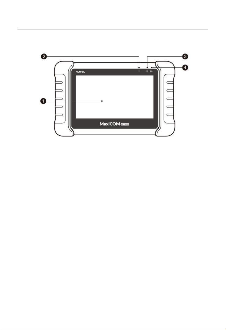
MaxiCOM MK808BT Display Tablet
Functional Description
1. 7.0” LCD Capacitive Touchscreen.
2. Ambient Light Sensor – detects ambient brightness.
3. Power LED – indicates battery level & charging or system status.
4. Vehicle Communication LED – flashes green when the Display
Tablet is communicating/linking with the vehicle’s system.
The power LED displays green, yellow or green depending on power level
and operating state.
A. Green
Illuminates green when the Display Tablet is charging and
the battery level is above 90%.
Illuminates green when the Display Tablet is powered on
and the battery level is above 15%.
B. Yellow
Illuminates yellow when the Display Tablet is charging and
the battery level is below 90%.
C. Red
Illuminates red when the Display Tablet is powered on and
the battery level is below 15%.
Figure 2- 1 Display Tablet Front View
Page 12
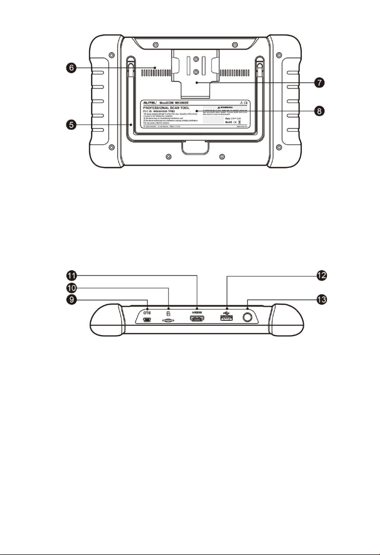
5
5. Collapsible Stand – extends from the back to allow hands-free
viewing of the Display Tablet.
6. Heat Sink
7. MaxiVCI Mini Holder
8. Built-in Battery
Figure 2- 3 Display Tablet Top View
9. Mini USB OTG Port
10. Micro SD Card Slot – holds the micro SD card.
11. HDMI (High-Definition Multimedia Interface) Port
12. USB Port
13. Lock/Power Button – turns the device on & off with long press, or
locks the screen with short press.
Power Sources
The tablet can receive power from any of the following sources:
Internal Battery Pack
Figure 2- 2 Display Tablet Back View
Page 13

6
External Power Supply
Internal Battery Pack
The tablet can be powered with the internal rechargeable battery, which if
fully charged can provide sufficient power for about 7 hours of continuous
operation.
External Power Supply
The tablet can be powered from a wall socket using the USB charging
cable and the USB external power adapter. The external power supply
also charges the internal battery pack.
Technical Specifications
Table 2- 1 Specifications
Item
Description
Recommended Use
Indoor
Operating System
AndroidTM4.4.2, KitKat
Processor
Cortex-A9 processor (1.5 GHz)
Memory
32GB
Display
7-inch LCD capacitive touchscreen with
1024 x 600 resolution
Connectivity
Mini USB 2.0
USB 2.0
Wi-Fi
HDMI Type A
Micro SD card (supports up to 32GB)
Sensors
Light sensor for brightness auto changing
Audio input/output
Input: N/A
Output: buzzer
Power and Battery
3.7 V/5000 mAh lithium-polymer
battery
Page 14

7
Item
Description
Charges via 5 VDC power supply
Tested Battery Life
Around 7 hours of continuous use
Battery Charging
Input
5 V/1.5 A
Power Consumption
600 mA (LCD on with default brightness,
Wi-Fi on) @3.7 V
Operating Temp.
0 to 55°C(32 to 131°F)
Storage Temp.
-20 to 60°C (-4 to 140°F)
Operating Humidity
5% - 95% non-condensing
Dimensions (
W x H x D
)
237.8 mm (9.4”) x 148.6 mm (5.9”) x 35.5
mm (1.4”)
Net Weight
788 g (2.42 lb.)
Protocols
ISO9141-2, ISO14230-2, ISO15765,
K/L-Line, Flashing Code, SAE-J1850
VPW, SAE-J1850PWM, ISO11898
(Highspeed, Middlespeed, Lowspeed and
Singlewire CAN, fault-tolerant CAN), SAE
J2610,GM UART,UART Echo Byte
Protocol, Honda Diag-H Protocol, TP2.0,
TP1.6
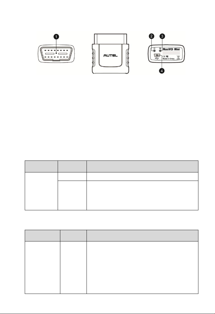
VCI – Vehicle Communication Interface
The wireless diagnostic interface MaxiVCI Mini is a small vehicle
communication interface (VCI) used to connect to a vehicle’s data link
connector (DLC) and connect wirelessly with the tablet for vehicle data
transmission.
Page 15
8
Functional Description
1. Vehicle Data Connector (16-Pin) – connects the MaxiVCI Mini to the
vehicle’s 16-pin DLC directly.
2. Power LED – refer to Table 2- 2 Power LED on the Front Panel on
page 8 for details.
3. Connection LED – refer to Table 2- 3 Connection LED on the Front
Panel on page 8 for details.
4. USB Port – provides the easiest connection between the device and
the tablet via a USB cable.
Table 2- 2 Power LED on the Front Panel
LED
Color
Description
Power
Green
Lights solid green when powered on.
Red
Blinks red when system failure occurs.
Note: The power LED briefly lights red each
time the device powers on and then lights
green when the device is ready.
Table 2- 3 Connection LED on the Front Panel
LED
Colo
Description
Connection
Green
Lights solid green when the device is
successfully connected via the USB
cable but is not communicating with the
vehicle.
Blinks green when the device is
successfully connected via the USB
cable and is communicating with the
vehicle.
Figure 2- 4 MaxiVCI Mini Views
Page 16

9
LED
Colo
Description
Blue
Lights solid blue when the device is
successfully connected via BT but is not
communicating with the vehicle.
Blinks blue when the device is
successfully connected via BT and is
communicating with the vehicle.
Technical Specifications
Table 2- 4 Specifications
Item
Description
Communications
BT V.2.1 + EDR
USB 2.0
Wireless Frequency
2.4 GHz
Input Voltage Range
12 VDC to 24 VDC
Supply Current
150 mA @ 12 VDC
Operating
0°C to 50°C (ambient)
Storage
-20°C to 70°C (ambient)
Dimensions
(L x W x H)
47 mm (1.7”) x 23 mm (0.9”) x 51 mm
(2.0”)
Weight
33.1g (0.07 lb.)
Power Sources
The MaxiVCI Mini operates on 12-volt vehicle power, which is received
through the vehicle’s DLC. The unit powers on whenever it is connected
to the vehicle’s DLC.
Page 17
10
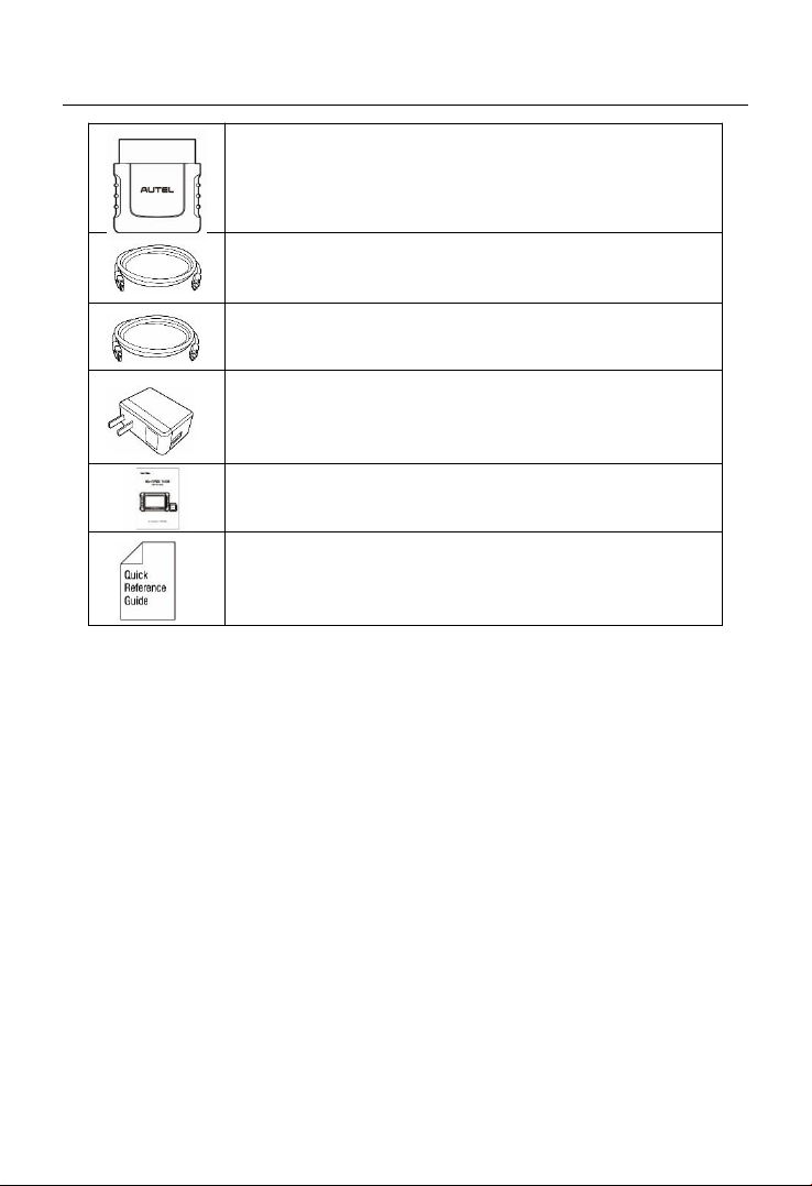
Other Accessories
MaxiVCI Mini
Connects to the vehicle’s DLC and provides wireless
connection between the tablet and the vehicle.
USB Cable (for test)
2 m
USB Cable (for charging)
90 cm
USB External Power Adapter
Together with the mini USB cable, connects the
tablet to the external DC power port for power supply.
User Manual
Tool operations instructions.
Quick Reference Guide
Device connection, MaxiVCI Mini and diagnostic
software update instructions.
Page 18
11
3 Getting Started
Ensure the tablet is sufficient charged or is connected to the external
power supply (see Power Sources on page 5).
NOTE
The images and illustrations depicted in this manual may differ slightly
from the actual ones.
Powering Up
Long press the Lock/Power button on the top right side of the tablet to
power on the unit. The power LED light will illuminate green. The system
boots up and displays the lock screen. Slide the Lock icon to the left to
enter the MaxiCOM Job Menu or slide to the right to unlock.
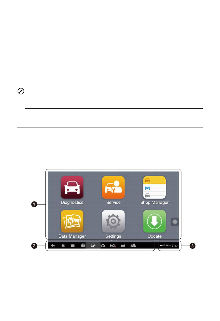
Figure 3- 1 Sample MaxiCOM MK808BT Job Menu
1. Application Buttons
2. Locator and Navigation Buttons
3. Status Icons
Page 19
12
NOTE
The tablet screen is locked by default when first powered on. It is
recommended to lock the screen to protect the information in the system
and reduce the power consumption.
The touch screen navigation is menu driven enabling quickly access to
functions and features by tapping on options headings and answering
dialog windows. Detailed descriptions of the menu structures are found in
the application chapters.
Application Buttons
Descriptions of the tool applications are displayed in the table below.
Table 3-1 Applications
Button
Name
Description
Diagnostics
Accesses diagnostic functions menu. See
Diagnostics on page 17.
Service
Accesses special functions menu. See
Service on page 47.
Shop
Manager
Allows you to edit and save workshop
information and customer data, as well as
reviewing test vehicle history records. See
Shop Manager on page 93.
Data
Manager
Accesses the organization system for saved
data files. See Data Manager on page 错误!
未定义书签。.
Settings
Accesses MaxiCOM system settings menu
and general tablet menu. See Settings on
page 77.
Update
Checks for the latest update available for the
MaxiCOM system, and performs updates. See
Update on page 86.
Page 20
13
Button
Name
Description
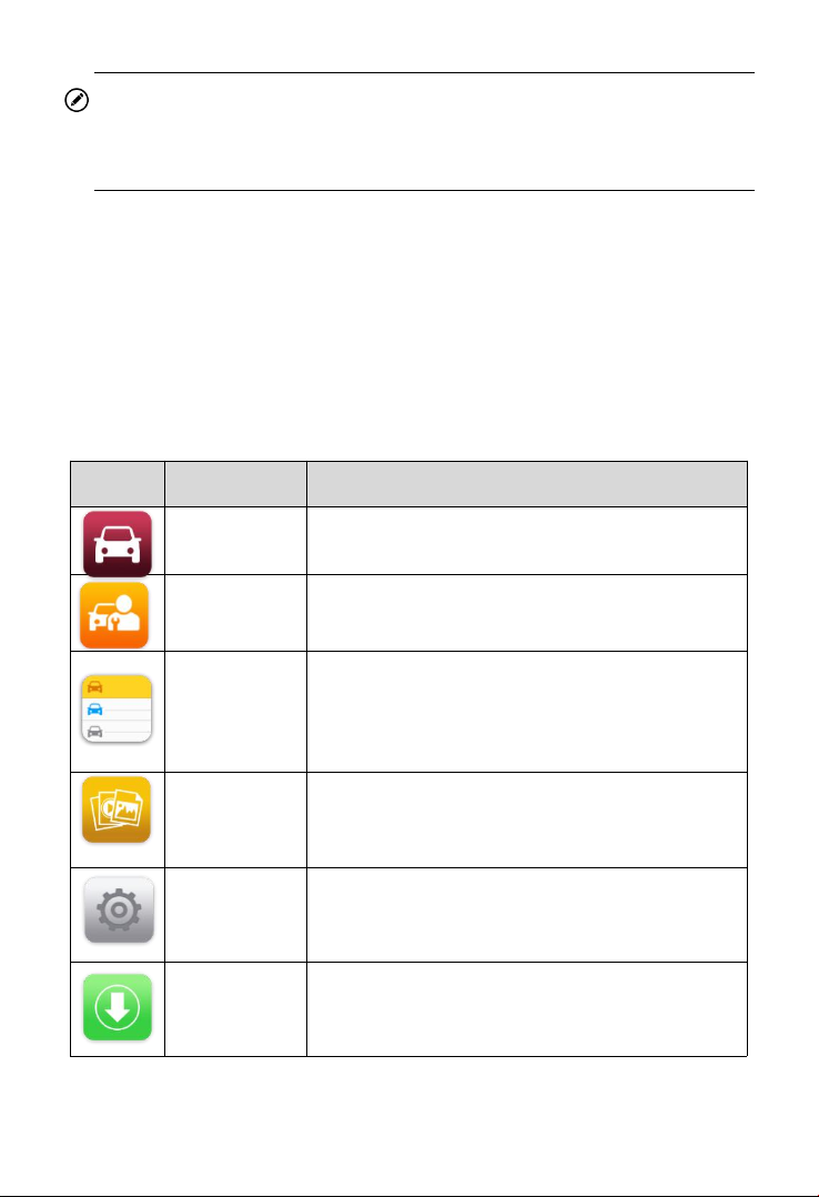
Support
Launches the Support platform which
synchronizes Autel’s on-line service base
station with the MaxiCOM tablet. See Support
on page 114.
Academy
Accesses technical tutorials and training
articles about the device usage and vehicle
diagnostic techniques. See Academy on page
101 for details.
Remote
Desk
Configures the unit to receive remote support
using the TeamViewer application program.
See Remote Desk on page 错 误 ! 未 定义 书
签。.
MaxiFix
Launches the MaxiFix platform which provides
the most compatible and abundant repair
techniques and diagnostics database. See
MaxiFix on page 104.
Quick Link
Provides associated website bookmarks to
allow quick access to product update, service,
support and other information. See Quick Link
on page 123.
Function
Viewer
Provides quick search for the supported
functions and vehicles of Autel diagnostic
tools
. See
Function Viewer on page
124.
Locator and Navigation Buttons
Operations of the Navigation buttons at the bottom of the screen are
described in the table below:
Table 3- 2 Locator and Navigation Buttons
Page 21
14
Button
Name
Description
Locator
Indicates which screen you are on. Swipe
the screen left or right to view the previous or
next screen.
Back
Returns to the previous screen.
Android
Home
Returns to Android System’s Home screen.
Recent
Apps
Displays a list of applications that are
currently in use. Tap an app icon to launch.
To remove an app, swipe it to the top or
bottom.
Chrome
Launches the Android built-in browser.
Screenshot
Takes a screenshot when you want to save
the displayed information.
MaxiCOM
Home
Returns to MaxiCOM Job Menu from other
operations.
VCI
Opens the VCI Manager application. The
check at the bottom right corner indicates the
tablet is communicating with the MaxiVCI
Mini. An X will display if the tablet is not
connected to VCI.
Diagnostics
Shortcut
Returns to the Diagnostics screen.
Service
Shortcut
Returns to the Service screen.
System Status Icons
As the tablet is working with the Android operating system, you may refer
to Android documents for more information.
Page 22
15
By up sliding the bottom right corner, a Shortcuts Panel will be displayed,
on which you are allowed to set various system settings of the tablet.
Operations of each button on the panel are described in the table below:
NOTE
The shortcuts buttons will be highlighted when enabled, and dimmed
when disabled.
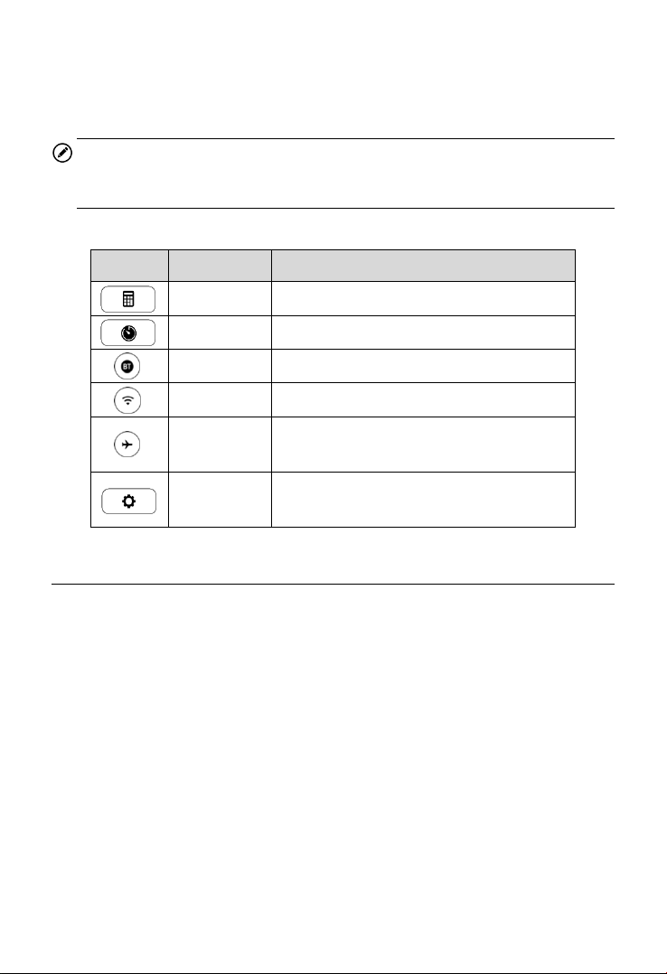
Table 3- 3 System Status Icons
Button
Name
Description
Calculator
Launches calculator when pressed.
Clock
Launches clock when pressed.
BT
Enables/disables BT when pressed.
Wi-Fi
Enables/disables Wi-Fi when pressed.
Airplane
Mode
Enables/disables Airplane Mode when
pressed.
System
Settings
Launches the Android System Settings
screen when pressed.
Powering Down
All vehicle communications must be terminated before shutting down the
tablet. A warning message displays if you attempt to shut down the tablet
while it is communicating with the vehicle. Forcing a shut-down while
communicating may lead to ECM problems on some vehicles. Please exit
the Diagnostics application before powering down.
To power down the tablet
1. Long press the Lock/Power Button.
2. Tap Power off option.
3. Tap OK, the tablet will turn off in a few seconds.
Page 23

16
Reboot System
In case of system crash, long press the Lock/Power button and tap
Reboot option to reboot the system.
Page 24

17
4 Diagnostics
The Diagnostics application can retrieve ECU information, read & erase
DTCs, and view live data. The Diagnostics application can access the
electronic control unit (ECU) for various vehicle control systems, including
engine, transmission, antilock brake system (ABS), airbag system (SRS).
Establishing Vehicle Communication
The Diagnostics operations require connecting the MK808BT Diagnostic
Platform to the test vehicle through the MaxiVCI Mini. To establish proper
vehicle communication to the tablet, please perform the following steps:
1. Connect the MaxiVCI Mini to the vehicle’s DLC for both
communication and power supply.
2. Connect the MaxiVCI Mini to the tablet via BT pairing.
3. A green check will display atop the VCI navigation button at the
bottom bar on the screen. If communication has been established,
the MK808BT is ready to start vehicle diagnosis.
Vehicle Connection
The tablet communicates with the vehicle via the BT connection provided
by the MaxiVCI Mini.
To connect the MaxiVCI Mini to the test vehicle, simply insert the Vehicle
Data Connector on the MaxiVCI Mini into the vehicle’s DLC which is
generally located under the vehicle dash and the MaxiVCI Mini will be
automatically powered on.
NOTE
The vehicle’s DLC is not always located under the dash; refer to the
vehicle’s user manual for DLC location.
Page 25

18
VCI Connection
The MaxiVCI Mini Power LED will light solid green when properly
connected to the vehicle and ready to establish communication with the
tablet.
The wireless diagnostic interface MaxiVCI Mini supports 2 communication
methods with the tablet, wireless BT and USB.
BT Connection
BT pairing is recommended as the first choice for the communication
between the tablet and the MaxiVCI Mini. The working range for BT
communication is about 33 feet (about 10 m), enabling remote vehicle
diagnostics.
More than one MaxiVCI Mini to connect to the test vehicles, you can
perform vehicle diagnosis on various vehicles conveniently by pairing the
tablet separately to each of the MaxiVCI Mini devices connected to the
different test vehicles via wireless BT. Without the need to repeat the
plugging and unplugging procedure which is unavoidable through
traditional wired connection, BT connection saves you more time and
provides higher efficiency.
Refer to BT Pairing on page 91 for details.
USB Cable Connection
Use the provided USB cable to connect the tablet to the MaxiVCI Mini. A
green check will display atop the VCI navigation button at the bottom bar
of the screen and the MaxiVCI Mini Connection LED will light solid green
when connection between the devices is successful.
NOTE
The USB communication method will take priority over BT communication
if both are enabled.
No Communication Message
A. If the tablet is not connected to the MaxiVCI Mini correctly, an “Error”
message may display. This indicates that the tablet cannot access
the vehicle control module. In this case, please do the following
Page 26

19
check-ups:
Check if the MaxiVCI Mini is powered up.
Check if the MaxiVCI Mini is properly positioned.
Check if the Connection LED on the MaxiVCI Mini is illuminated for
BT or USB.
In case of BT connection, check if the network is configured
correctly, or if the right MaxiVCI Mini has been paired up with the
tablet.
If during the diagnosis process, the communication is
suddenly interrupted due to the loss of signal, check if there
is any object that causes signal interruption.
Try standing closer to the MaxiVCI Mini to obtain more stable
signals and faster communication speed.
In case of USB connection, check the cable connection between
the tablet and the MaxiVCI Mini.
Check if the Power LED on the MaxiVCI Mini is flashing red and if
so, it indicates there is a hardware problem with the MaxiVCI
Mini, in this case, contact technical support for help.
B. If the MaxiVCI Mini is unable to establish a communication link, a
prompt message displays with check instructions. The following
conditions are the possible causes:
The MaxiVCI Mini is unable to establish a communication link with
the vehicle.
The system selected for testing is not equipped on the vehicle.
There is a loose connection.
There is a blown vehicle fuse.
There is a wiring fault of the vehicle or the adapter.
There is a circuit fault in the adapter.
Incorrect vehicle identification was entered.
Getting Started
Ensure a communication link is established between the test vehicle and
the tablet via the MaxiVCI Mini.
Page 27
20
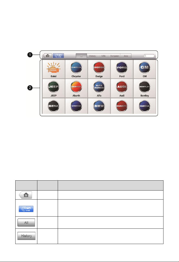
Vehicle Menu Layout
When the tablet device is properly connected to the vehicle, the platform
is ready to start vehicle diagnosis. Tap on the Diagnostics application
button on the MaxiCOM MK808BT Job Menu to access the Vehicle Menu.
1. Top Toolbar Buttons
2. Vehicle Manufacturer Buttons
Top Toolbar Buttons
The operations of the toolbar buttons at the top of the screen are listed
and described in the table below:
Table 4- 1 Top Toolbar Buttons
Button
Name
Description
Home
Returns to the MaxiCOM Job Menu.
VIN
Scan
Provides a fast way to identify the test vehicle. See
Vehicle Identification on page 21 for details.
All
Displays all the vehicle manufacturers.
History
Displays the stored test vehicle history records.
See Vehicle History on page 94 for details.
Figure 4- 1 Sample Vehicle Menu
Page 28

21
USA
Displays the USA vehicle menu.
Europe
Displays the European vehicle menu.
Asia
Displays the Asian vehicle menu.
Search
Searches for a specific vehicle make.
Cancel
Exits the search screen or cancels an operation.
Vehicle Manufacturer Buttons
To begin, select the manufacturer button of the test vehicle, followed by
the vehicle mode and year.
Vehicle Identification
The MaxiCOM diagnostic system supports four methods for Vehicle
Identification.
1. Auto VIN Scan
2. Manual VIN Input
3. Automatic Selection
4. Manual Selection
Auto VIN Scan
The MaxiCOM diagnostic system features the latest VIN-based Auto VIN
Scan function to identify vehicles and scan all the diagnosable ECUs and
run diagnostics on the selected system. This function is compatible with
2006 and newer vehicles.
To perform Auto VIN Scan
1. Tap the Diagnostics application button from the MaxiCOM Job
Menu. The Vehicle Menu displays.
2. Tap the VIN Scan button on the top toolbar to open the dropdown
list.
Page 29
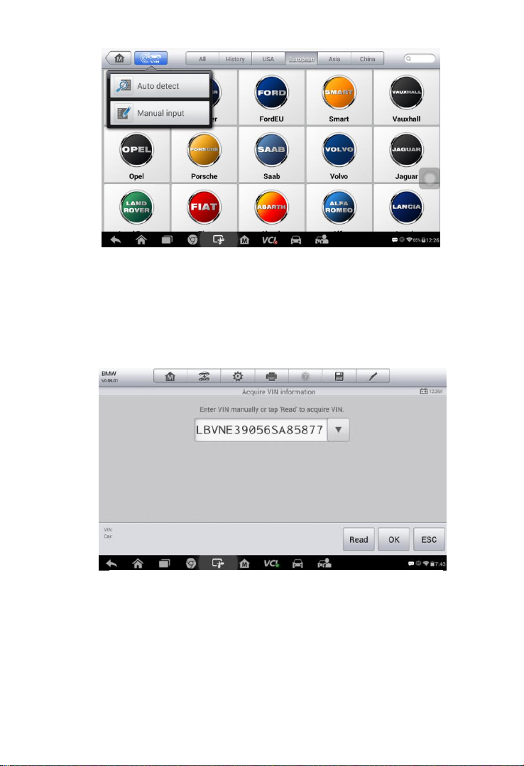
22
3. Select Auto Detect. Once the test vehicle is identified, the screen
will display the vehicle VIN. Tap OK at the bottom right to confirm
the vehicle VIN. If the VIN does not match with the test vehicle’s
VIN, enter VIN manually or tap Read to acquire VIN again.
4. Tap OK to confirm the vehicle profile or NO if the information is not
correct.
Figure 4- 2 Sample Auto VIN Screen
Figure 4- 3 Sample Auto Detect Screen
Page 30
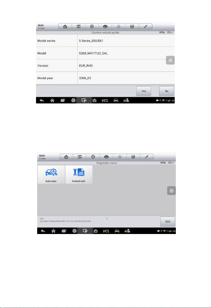
23
Figure 4- 4 Sample Vehicle Profile Screen
5. The tool establishes communication with the vehicle and reads the
control unit information. Choose Auto Scan to scan all the test
vehicles’ available systems or tap Control Unit to access a
specific system to diagnose.
Figure 4- 5 Sample Diagnostic Screen
Page 31

24
Manual VIN Input
For vehicles not supporting the Auto VIN Scan function, you may
manually enter the vehicle VIN.
To perform Manual VIN Input
1. Tap the Diagnostics application button from the MaxiCOM Job
Menu. The Vehicle Menu displays.
2. Tap the VIN Scan button on the top toolbar to open the dropdown
list.
3. Select Manual Input.
4. Tap the input box and enter the correct VIN.
5. Tap Done. Once the vehicle is identified, the Vehicle Diagnostics
screen displays.
6. Tap Cancel to exit Manual Input.
Figure 4- 6 Sample Diagnostic Screen
Page 32

25
Automatic Selection
The Auto VIN Scan can be selected after selecting the test vehicle
manufacturer.
To perform Automatic Selection
1. Tap the Diagnostics application button from the MaxiCOM Job
Menu. The Vehicle Menu displays.
2. Tap the manufacturer button of the test vehicle.
3. Tap Automatic Selection and the VIN information will be acquired
automatically. Follow the on-screen instruction to display the
diagnostic screen.
Manual Selection
When the vehicle’s VIN is not automatically retrievable through the
vehicle's ECU, or the specific VIN is unknown, the vehicle can be
manually selected.
This mode of vehicle selection is menu driven, repeat the first two steps
from the automatic selection operation and tap Manual Selection.
Through a series of on-screen prompts and selections, the test vehicle is
chosen. If needed, press the Back button at the bottom right corner of the
screen to return to previous screen.
Figure 4- 7 Sample Selection Screen
Page 33

26
Navigation
Navigating the Diagnostics interface and selecting test are discussed in
this section.
Diagnostics Screen Layout
The diagnostic screens typically include four sections.
1. Diagnostics Toolbar
2. Status Information Bar
3. Main Section
4. Functional Buttons
Diagnostics Toolbar
The Diagnostics Toolbar contains a number of buttons such as print and
save. The table below provides a brief description of the operations of the
Diagnostics Toolbar buttons.
Figure 4- 8 Sample Diagnostics Screen
Page 34
27
Table 4- 2 Diagnostics Toolbar Buttons
Button
Name
Description
Home
Returns to the MaxiCOM Job Menu.
Vehicle
Swap
Exits the service session of the currently identified
test vehicle and returns to the vehicle menu
screen.
Settings
Opens the settings screen. See Settings on page
77 for details.
Print
Prints a copy of the displayed data. See Printing
Setting on page 79 for details.
Help
Displays operations instructions or tips.
Save
Saves the current page. See Data Manager on
page 72 for details.
Data
Logging
Records the communication data and ECU
information of the test vehicle. See Data Logging
on page 119 for details.
To print data in Diagnostics
1. Tap the Diagnostics application button from the MaxiCOM Job
Menu. The Print button on the diagnostic toolbar is available
throughout the Diagnostics operations.
2. Tap Print. A drop-down menu displays. Tap Print This Page to
print a screen shot copy of the current screen.
3. A temporary file will be created and sent to the connected
computer for printing.
4. When the file is transferred successfully, a confirmation message
displays.
To submit Data Logging reports in Diagnostics
1. Tap the Diagnostics application button from the MK808BT Job
Menu. The Data Logging button on the diagnostic toolbar is
available throughout the Diagnostics operations.
Page 35

28
2. Tap the Data Logging button. The button displays blue during the
active recording process.
3. Tap the Data Logging button again to end recording. A submission
form will display for inputting of the report information.
4. Tap the Send button to submit the report form via the Internet. A
confirmation message displays when the report has been
successful sent.
Status Information Bar
The Status Information Bar at the top of the Main Section displays the
following items:
1. Menu Title – displays the menu heading of the Main Section.
2. Voltage Icon – displays the vehicle’s voltage status.
Main Section
The Main Section of the screen varies according to the stage of
operations. The Main Section can display vehicle identification selections,
the main menu, test data, messages, instructions and other diagnostic
information.
Functional Buttons
The displayed Functional Buttons vary depending on the stage of
operations. Functional Buttons can be used to navigate menus, to save or
clear diagnostic data, to exit scanning and to perform a number of other
control functions. The use of these buttons will be discussed in detail in
the following sections of the corresponding test operations.
Screen Messages
Screen messages appear when additional input is needed before
proceeding. There are three main types of on-screen messages:
Confirmation, Warning, and Error.
Page 36

29
Confirmation Messages
This type of messages usually displays as an “Information” screen, to
inform the user that a selected action cannot be reversed or when an
action has been initiated and confirmation is needed to continue.
When a user-response is not required to continue, the message displays
briefly.
Warning Messages
This type of messages displays a warning that a selected action may
result in an irreversible change or loss of data. An example of this type of
message is the “Erase Codes” message.
Error Messages
Error messages display when a system or procedural error has occurred.
Examples of possible errors include a disconnection or communication
interruption.
Making Selections
The Diagnostics application is a menu driven program that presents a
series of choices. As a selection is made, the next menu in the series
displays. Each selection narrows the focus and leads to the desired test.
Tap the screen to make menu selections.
Diagnosis
The Diagnostics application enables a data link to the electronic control
system of the test vehicle for vehicle diagnosis. The application performs
functional tests, retrieves vehicle diagnostic information such as trouble
and event codes and live data from various vehicle control systems such
as engine, transmission, ABS.
There are two options available when accessing the Diagnosis section:
1. Auto Scan – starts auto scanning for all the available systems on the
vehicle.
2. Control Units – displays a selection menu of all available control units
Page 37

30
of the test vehicle.
After a selection is made and the tablet establishes communication with
the vehicle, the corresponding function menu or selection menu displays.
Auto Scan
The Auto Scan function performs a comprehensive scanning over all the
ECUs in the vehicle’s ECU to locate systems faults and retrieve DTCs. An
example of Auto Scan interface is pictured as below:
1. Navigation Bar
2. Main Section
3. Functional Buttons
Navigation Bar
List Tab – displays the scanned data in list format.
Progress Bar – indicates the test progress.
Main Section
Column 1 – displays the sequence numbers.
Column 2 – displays the scanned systems.
Column 3 – displays the diagnostic indicators describing test results:
Figure 4- 9 Sample Auto Scan Operation Screen
Page 38

31
These indicators are defined as follows:
-!-: Indicates that the scanned system may not support the code
reading function, or there is a communication error between the
tablet and the control system.
-?-: Indicates that the vehicle control system has been detected,
but the tablet cannot accurately locate it.
Fault(s) | #: Fault(s) indicates there is/are detected fault code(s)
present; “#” indicates the number of the detected faults.
Pass | No Fault: Indicates the system has passed the scanning
process and no fault has been detected.
Column 4 – to perform further diagnosis or testing on a specific system
item, tap the○>
button to the right of that item. A Function Menu screen
will display.
Functional Buttons
A brief description of the Auto Scan’s Functional Buttons’ operations are
displayed in the table below.
Table 4-3 Functional Buttons
Name
Description
Report
Displays the diagnostic data in the report form.
Quick
Erase
Deletes codes. A warning message screen will display
to inform you of possible data loss when this function is
selected.
OK
Confirms the test result. Continues to the system
diagnosis after required system is selected by tapping
the item in the Main Section.
Pause
Suspends scanning and it will change to Continue
button after tapping.
ESC
Returns to the previous screen or exits Auto Scan.
Page 39

32
Control Units
Manually locate a required control system for testing through a series of
choices. Follow the menu driven procedures and make proper selections;
the application guides the user to the proper diagnostic function menu
based on selections.
The Function Menu options vary slightly for different vehicles. The
function menu may include:
ECU Information – provides the retrieved ECU information in detail. An
information screen opens upon selection.
Read Codes – displays detailed information of DTC records retrieved
from the test vehicle’s ECU.
Erase Codes – erases DTC records and other data from the test
vehicle’s ECU.
Live Data – retrieves and displays live data and parameters from the
test vehicle’s ECU.
NOTE
Toolbar functions such as saving and printing of test results can be
performed throughout diagnostic testing. Data logging and access to help
information are also available.
To perform a diagnostic function
1. Establish communication with the test vehicle.
2. Identify the test vehicle by selecting from the menu options.
Figure 4- 10 Sample Function Menu
Page 40
33
3. Select the Diagnosis section.
4. Locate the required system for testing by Auto Scan or through
menu driven selections in Control Units.
5. Select the desired diagnostic function from the Function Menu.
ECU Information
This function retrieves and displays the specific information for the tested
control unit, including unit type, version numbers and other specifications.
The sample ECU Information screen displays as below:
1. Diagnostics Toolbar Buttons – see Table 4- 2 Diagnostics Toolbar
Buttons on page 27 for detailed descriptions of the operations for
each button.
2. Main Section – the left column displays the item names; the right
column shows the specifications or descriptions.
3. Functional Button – ESC (a Back) button is available; tap it to exit
after viewing.
Read Codes
This function retrieves and displays the DTCs from the vehicle’s control
system. The Read Codes screen varies for each vehicle being tested. On
some vehicles, freeze frame data can also be retrieved for viewing. The
sample Read Codes screen displays as below:
Figure 4- 11 Sample ECU Information Screen
Page 41

34
1. Diagnostics Toolbar Buttons – see Table 4- 2 Diagnostics Toolbar
Buttons on page 27 for detailed descriptions of the operations for
2. Main Section
Code Column – displays the retrieved codes from the vehicle.
Status Column – indicates the status of the retrieved codes.
Description Column – detailed descriptions for the retrieved codes.
Snowflake Icon – only displays when freeze frame data is available
for viewing; selecting this icon will display a data screen, which
looks behaves similar to the Read Codes screen.
3. Functional Button
Help – tap to view fault code information, including fault description,
condition for fault identification and driver information.
Freeze Frame – tap to view the freeze frame.
Search – tap to search for related fault code information on
Google.
ESC – tap to return to the previous screen or exit the function.
Erase Codes
After reading the retrieved codes and making appropriate vehicle repairs,
use this function to erase vehicle codes.
To erase codes
Figure 4- 12 Sample Read Codes Screen
each button.
Page 42
35
1. Tap Erase Codes from the Function Menu.
2. A warning message displays to advise of data loss if this function is
completed.
a) Tap Yes to continue. A confirming screen displays when the
operation is successfully done.
b) Tap No to exit.
3. Tap ESC on the confirming screen to exit Erase Codes.
4. Perform the Read Codes function again to check if codes have
been erased successfully.
Live Data
When this function is selected, the screen displays the data list for the
selected module. The items available for any control module vary by
vehicle. The parameters display in the order that they are transmitted by
the ECM, so expect variation between vehicles.
Gesture scrolling allows for quick movement through data list. Using one
or two fingers, simply swipe the screen up or down to locate the data you
want. The figure below shows a typical Live Data screen:
1. Diagnostics Toolbar Buttons – tap the drop-down button at the top
center of the screen and the toolbar buttons will display. See on Table
4- 2 Diagnostics Toolbar Buttons page 27 for detailed descriptions of
the operations for each button.
2. Main Section
Figure 4- 13 Sample Live Data Screen
Page 43

36
Name Column – displays the parameter names.
a) Check Box – tap the check box on the left side of the
parameter name to make item selection. Tap the check box
again to deselect the item.
b) Drop-down Button – tap the drop-down button on the right
side of the parameter name to open a sub menu, providing
data display mode options.
Value Column – displays the values of the parameter items.
Unit Column – displays the unit for the parameters.
To change the unit mode, tap the Setting button on the top
toolbar and select a required mode. See Unit on page 77 for
more information.
Display Mode
There are four types of display modes available for data viewing.
Select the proper mode for the diagnostic purpose.
Tap the drop-down button on the right side of the parameter name to
open a sub menu. There are four buttons to configure the data
display mode, and one Help button on the right for access to
additional information.
Each parameter item displays the selected mode independently.
1) Analog Gauge Mode – displays the parameters in the form of an
analog meter graph.
2) Text Mode – this is the default mode which displays the
parameters text, displaying in list format.
NOTE
Status parameters, such as a switch reading, can primarily be viewed in
text form such as ON, OFF, ACTIVE, and ABORT. Whereas, value
parameter, such as a sensor reading, can be displayed in text mode and
additional graph modes.
3) Waveform Graph Mode – displays the parameters in waveform
graphs.
When this mode is selected, three control buttons display on the right
side of the parameter item for manipulation of display status.
Text Button – resumes Text Display Mode.
Page 44

37
Scale Button – changes the scale values that are displayed below
the waveform graph. There are four scales available: x1, x2, x4
and x8.
Zoom-in Button – tap once to display the selected data graph in full
screen.
Edit Button – tap this button to open an edit window, on which
you can set the waveform color and the line thickness
displayed for the selected parameter item.
Scale Button - changes the scale values, which are displayed
below the waveform graph. There are four scales available:
x1, x2, x4 and x8.
Zoom-out Button – exits full screen display.
4) Digital Gauge Mode – displays the parameters in form of a digital
gauge graph.
Full Screen Display – this option is only available in the waveform
graph mode, and primarily in Graph Merge status for data
comparison. Under this mode, there are three control buttons
available on the top right side of the screen.
To edit the waveform color and line thickness in a data graph
1. Select one to three parameter items to display in Waveform
Graph mode.
2. Tap the Zoom-in Button on the right to display the data
graph in full screen.
3. Select a parameter item on the left column.
4. Select a desired sample color from the middle column.
5. Select a desired sample line thickness from the right column.
6. Repeat step 3-5 to edit the waveform for each parameter
item.
7. Tap Done to save the setting and exit, or tap Cancel to exit
without saving.
3. Functional Buttons
The operations of available functional buttons on Live Data screen
are described below:
Back – returns to the previous screen or exits the function.
Page 45

38
Record – starts recording the retrieved live data; the recorded data is
then stored as a video clip in the Data Manager application for future
review. This function can be triggered automatically at preset
threshold value or values may be set manually. The triggering mode
and record duration can be configured in the Setting mode of Live
Data.
Freeze Frame – displays the retrieved data in freeze frame mode.
Previous Frame – displays previous frame of the freeze data.
Next Frame – advances to the next frame in the freeze data.
Clear Data – clears all previously retrieved parameter values at a
cutting point.
To Top – moves a selected data item to the top of the list.
Graph Merge – tap this button to merge selected data graphs (for
Waveform Graph Mode only). This function is useful for comparison
between different parameters.
NOTE
In this mode, Graph Merge can only display up to three parameter items.
To cancel Graph Merge mode, tap the drop-down button on the right
side of the parameter name, and select a data display mode.
Show – tap this option to switch between the two options; one
displays the selected parameter items, the other displays all the
available items.
Setting – tap this button to access setting menu to set the trigger
mode, recording duration and threshold values for data recording,
and define other control settings.
Page 46

39
There are four navigation buttons on top of the Setting mode screen.
Selected Button – displays the configuration screen to set the threshold
values, an upper limit and a lower limit, for triggering the buzzer
alarm. This function is only applied to the Waveform Graph display
mode.
a) MIN – tap to display virtual keyboard and enter the required lower
limit value.
b) MAX – tap to display virtual keyboard and enter the required upper
limit value.
c) Buzzer Alarm – switches the alarm on and off. The alarm function
makes a beep sound as a reminder whenever the data reading
reaches the preset minimum or maximum point.
To set threshold limits for the parameter values
1. Tap the Setting functional button at the bottom of the Live Data
screen.
2. Tap the Selected navigation button.
3. Select a parameter item on the left column, or enter the item name
in the Search bar.
4. Tap on the right side of the MIN button, and enter the required
minimum value.
5. Tap on the right side of the MAX button, and enter the required
maximum value.
Figure 4- 14 Sample Setting Mode in Live Data
Page 47

40
6. Tap the ON/OFF button on the right side of the Buzzer Alarm
button to turn it on or off.
7. Tap Done to save the setting and return to the Live Data screen; or
tap Cancel to exit without saving.
If the threshold limits are successfully set, two horizontal lines will display
on each of the data graphs (when Waveform Graph Mode is applied) to
indicate the alarm point. The threshold lines are displayed in different
colors from the waveform of the parameters.
Record Button – displays the configuration screen for Record Setting, to
set the trigger type, duration and trigger point for the data recording
function.
a) Trigger Type – sets the trigger mode for data recording, Manual
and Auto. There are four options available:
1) Manual – manually starts and stops data recording.
2) DTC – auto triggers data recording when any DTC is
detected.
3) DTC Check Mode – auto triggers data recording when certain
pre-selected DTC types are detected.
4) Parameter – auto triggers data recording when any
parameter value reaches the preset threshold.
b) Duration – sets the recording time (for Auto trigger mode only).
c) Trigger Point – reserves a relative percentage of a record length
before the data recording start point for reference (for Auto
trigger mode only).
To perform setting for live data record
1. Tap the Setting functional button at the bottom of the Live Data
screen.
2. Tap the Record navigation button.
3. Tap the
○
>
button on the right of Trigger Type bar and select the
required trigger mode.
4. Tap the
○
>
button on the right of Duration bar and select a
length of time.
5. Tap the○>
button on the right of Trigger Point bar and select a
relative percentage of a record length to be reserved before the
Page 48

41
data recording start point.
6. Tap Done to save the setting and return to the Live Data screen; or
tap Cancel to cancel without saving and exit Setting.
Done Button - confirms and saves the setting, and returns to the Live
Data screen.
Cancel Button – cancels the setting operation, and returns to the Live
Data screen.
Generic OBD II Operations
This option presents a quick way to check for DTCs, isolate the cause of
an illuminated malfunction indicator lamp (MIL), check monitor status
prior to emissions certification testing, verify repairs, and perform a
number of other services that are emissions-related. The OBD direct
access option is also used for testing OBD II/EOBD compliant vehicles
that are not included in the Diagnostics database.
The diagnostics toolbar buttons at the top of the screen function the same
as those available for specific vehicle diagnostics. See Table 4- 2
Diagnostics Toolbar Buttons on page 27 for details.
General Procedure
To access the OBD II/EOBD diagnostics functions
1. Tap the Diagnostics application button from the MaxiCOM Job
Menu. The Vehicle Menu displays.
2. Tap the EOBD button. There are two options to establish
communication with the vehicle.
Auto Scan – when this option is selected, the diagnostic tool
attempts to establish communication using each protocol in
order to determine the one from which the vehicle is
broadcasting.
Protocol – when this option is selected, the screen opens a
sub menu listing various protocols. A communication
protocol is a standardized way of data communication
between an ECM and a diagnostic tool. Global OBD may
use several different communication protocols.
Page 49

42
3. Select a specific protocol under the Protocol option. Wait for the
OBD II Diagnostic Menu to display.
NOTE
Tapping the○i
button displayed beside the function name opens a
bubble with additional function information.
4. Select a function option to continue.
DTC & FFD
I/M Readiness
Live Data
On-Board Monitor
Component Test
Vehicle Information
Vehicle Status
NOTE
Not all functions are supported by all vehicle.
Function Descriptions
This section describes the various functions of each diagnostic option:
Figure 4- 15 Sample OBD II Diagnostic Menu
Page 50
43
DTC & FFD
When this function is selected, the screen displays a list of Stored and
Pending Codes. A snowflake button will display on the right side of the
DTC
item when the Freeze Frame data is available for viewing. Tap Clear DTC
to erase codes.
Stored Codes
Stored codes are the current emission-related DTCs from the ECM of
the vehicle. OBD II/EOBD Codes have a priority according to their
emission severity, with higher priority codes overwriting lower priority
codes. The priority of the code determines the illumination of the MIL
and the codes erase procedure. Manufacturers rank codes differently,
so expect to see differences between makes.
Pending Codes
These are codes that were generated during the last drive cycle, but
before the DTC actually sets, two or more consecutive drive cycles
are needed. The intended use of this service is to assist the service
technician after a vehicle repair and after clearing diagnostic
information, by reporting test results after a driving cycle.
a) If a test failed during the drive cycle, the DTC associated with that
test is reported. If the pending fault does not occur again within
40 to 80 warm-up cycles, the fault is automatically cleared from
Figure 4- 16 Sample DTC & FFD Screen
Page 51

44
memory.
b) Test results reported by this service do not necessarily indicate a
faulty component or system. If test results indicate another
failure after additional driving, then a DTC is set to indicate a
faulty component or system, and the MIL is illuminated.
Freeze Frame
Typically, the stored frame is the last DTC that occurred. Certain
DTCs that have a greater impact on vehicle emission, have a higher
priority. In these cases, the top prioritized DTC is the one for which
the freeze frame records are retained. Freeze frame data includes a
“snapshot” of critical parameter values at the time the DTC is set.
Clear DTC
This option is used to clear all emission related diagnostic data such
as DTCs, freeze frame data and manufacturer-specific enhanced
data from the vehicle’s ECM.
A confirmation screen displays when the clear codes option is
selected to prevent accidental loss of data. Select Yes to continue or
No to exit.
I/M Readiness
This function is used to check the readiness of the monitoring system. It is
an excellent function to use prior to having a vehicle inspected for state
emissions compliance. Select I/M Readiness to display a sub menu with
two choices:
Since DTCs Cleared – displays the status of monitors since the last
time the DTCs are erased.
This Driving Cycle – displays the status of monitors since the
beginning of the current drive cycle.
Live Data
This function displays the real time PID data from ECU. Displayed data
includes analog inputs and outputs, digital inputs and outputs, and system
status information broadcast on the vehicle data stream.
Live data can be displayed in various modes, see Live Data on page 35
for detailed information.
Page 52

45
On-Board Monitor
Use this option to view the results of On-Board Monitor tests. The tests
are useful after servicing or after erasing a vehicle’s control module
memory.
Component Test
This service enables bi-directional control of the ECM so that the
diagnostic tool is able to transmit control commands to operate the
vehicle systems. This function is useful in determining whether the ECM
responds to a command well.
Vehicle Information
The option displays the vehicle identification number (VIN), the calibration
identification, and the calibration verification number (CVN), and other
information of the test vehicle.
Vehicle Status
This option is used to check the current condition of the vehicle, including
communication protocols of OBD II modules, retrieved codes amount,
status of the Malfunction Indicator Light (MIL), and other additional
information.
Exiting Diagnostics
The Diagnostics application remains open as long as there is an active
communication with the vehicle. You must exit the diagnostics operation
to stop all communications with the vehicle before closing the Diagnostics
application.
NOTE
Damage to the vehicle electronic control module (ECM) may occur if
communication is disrupted. Make sure all connections, such as USB
cable and wireless connection, are properly connected at all times during
testing. Exit all tests before disconnecting the test connection or powering
down the tool.
To exit the Diagnostics application
Page 53

46
1. From an active diagnostic screen, tap the Back or ESC functional
button to exit a diagnostic session step-by-step.
2. Or tap the Vehicle Swap button on the diagnostics toolbar to
return to the Vehicle Menu screen.
3. From the Vehicle Menu screen, tap the Home button on the top
toolbar; or tap the Back button on the navigation bar at the
bottom of the screen.
4. Or tap the Home button on the diagnostics toolbar to exit the
application directly and go back to the MaxiCOM Job Menu.
Now, the Diagnostics application is no longer communicating with the
vehicle and it is safe to open other MaxiCOM applications, or exit the
MaxiCOM Diagnostic System and return to the Android System’s Home
screen.
Page 54

47
5 Service
The Service section is specially designed to provide quick access to the
vehicle systems for various scheduled service and maintenance tasks.
The typical service operation screen is a series of menu driven executive
commands. Follow on-screen instructions to select appropriate execution
options, enter correct values or data, and perform necessary actions. The
application will display detailed instructions to complete selected service
operations.
The most commonly performed service functions include:
Oil Reset Service
EPB Service
BMS Service
SAS Service
DPF Service
After entering each special function, the screen will display two
application choices: Diagnosis and Hot Functions. Diagnosis enables
the reading and clearing of codes which are sometimes necessary after
completing certain special functions. Hot Functions consists of sub
functions of the selected special function.
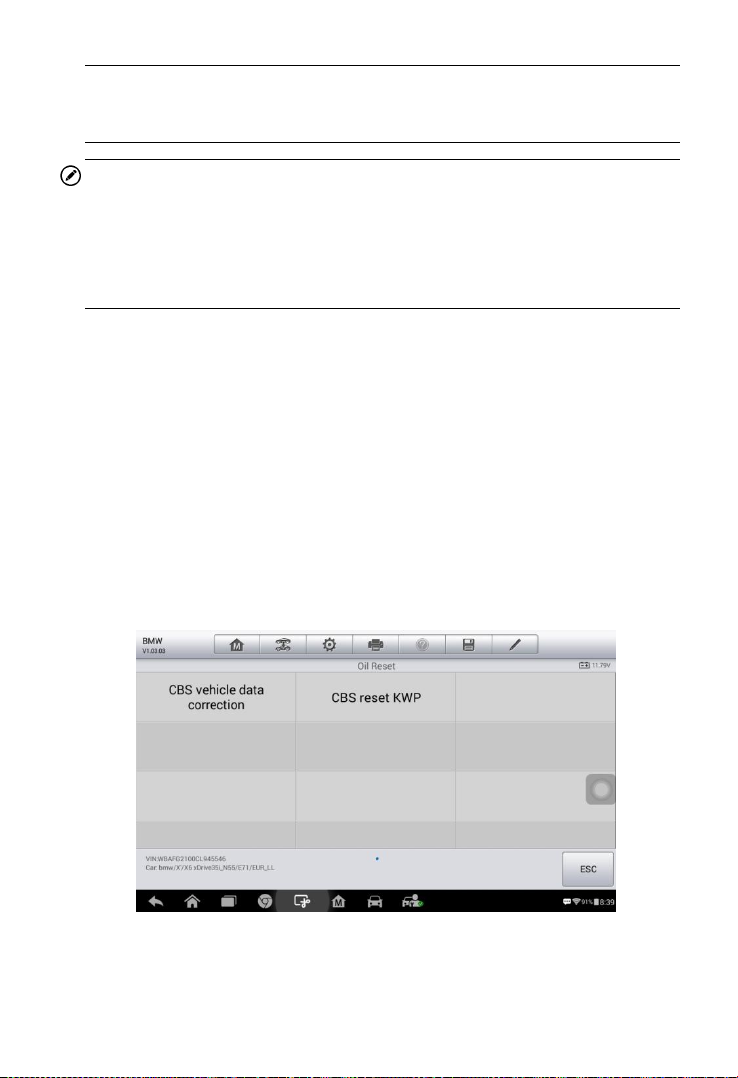
Oil Reset Service
Perform reset for the Engine Oil Life system, which calculates an optimal
oil life change interval depending on the vehicle driving conditions and
climate. The Oil Life Reminder must be reset each time the oil is changed,
so the system can calculate when the next oil change is required.
IMPORTANT
Always reset the engine oil life to 100% after every oil change.
NOTE
Page 55
48
All required work must be carried out before the service indicators are
reset. Failure to do so may result in incorrect service values and cause
DTCs to be stored by the relevant control module.
NOTE
For some vehicles, the scan tool can reset additional service lights such
as maintenance cycle and service interval. On BMW vehicles for an
example, service resets include engine oil, spark plugs, front/rear brakes,
coolant, particle filter, brake fluid, micro filter, vehicle inspection, exhaust
emission inspection and vehicle check.
All software screens shown in this manual are examples, actual test
screens may vary for each vehicle being tested. Observe the menu
headings and on-screen instructions to make correct selections.
To perform oil reset functions
1. Tap the Service application button from the MaxiCOM Job Menu.
2. Tap Oil Reset button. The vehicle manufacturer screen displays.
Tap VIN Scan or the vehicle make to acquire vehicle VIN
information and tap Yes to confirm. See Vehicle Identification on
page 21 for detail.
3. Tap the desired function in the Oil Reset function list. The list may
vary by test vehicle.
4. Follow the step-by-step on-screen instruction to complete the
service. Using CBS vehicle date correction as an example.
Figure 5- 1 Sample Oil Function List
Page 56

49
5. Tap CBS vehicle date correction on the Oil Reset function list to
start the operation. The screen will display the date and time and
ask for confirmation. If the displayed date and time are correct,
tap Yes to confirm. If not, tap No and go to the Settings menu to
set the correct date and time.
6. The available items will display in a table of four columns: CBS
value, availability, service counter and forecast.
7. Tap on the value you want to reset and then tap the Correction
button on the right bottom of the screen.
Figure 5- 2 Sample Oil Reset Service Screen 1
Figure 5- 3 Sample Oil Reset Service Screen 2
Page 57

50
8. The tool will display a function list menu as below. Press the
corresponding number button to perform the desired function.
Tap ESC to exit.
9. When the reset is done, the screen will display “Service function
finished”. Tap Continue to exit.
Figure 5- 4 Sample Oil Reset Service Screen 3
Figure 5- 5 Sample Oil Reset Service Screen 4
Page 58

51
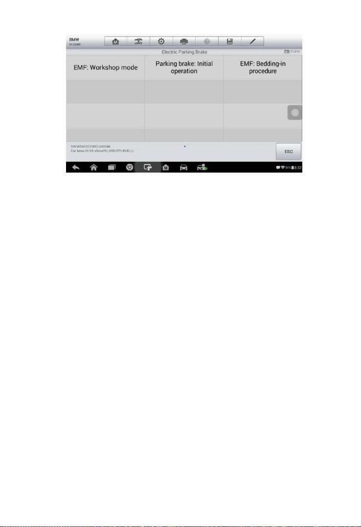
Electronic Parking Brake (EPB) Service
This function has a multitude of usages to maintain the electronic braking
system safely and effectively. The applications include deactivating and
activating the brake control system, assisting with brake fluid control,
opening and closing brake pads, and setting brakes after disc or pad
replacement, etc.
EPB Safety
It may be dangerous to perform Electronic Parking Brake (EPB) system
maintenance, so before you begin the service work, please keep these
rules in mind.
Ensure that you are fully familiar with the braking system and its
operation before commencing any work.
The EPB control system may be required to be deactivated before
carrying out any maintenance/diagnostic work on the brake system.
This can be done from the tool menu.
Only perform maintenance work when the vehicle is stationary and
on level ground.
Ensure that the EPB control system is reactivated after the
maintenance work has been completed.
NOTE
Autel accepts no responsibility for any accident or injury arising from the
maintenance of the Electronic Parking Brake system.
To perform EPB functions
1. Tap the Service application button from the MaxiCOM Job Menu.
2. Tap EPB button. The vehicle manufacturer selection screen will
display. Tap VIN Scan or the vehicle manufacturer to acquire
vehicle VIN information and tap Yes to confirm. See Vehicle
Identification on page 21 for detail.
3. Tap the desired service in the EPB function list. The list may vary
for different vehicles being tested.
Page 59
52
4. Follow the step-by-step on-screen instruction to complete the
service. Using Parking brake: Initial operation as an example.
5. Press ESC button to exit.
Parking brake: Initial operation
This service function would start up the parking brake. It must be
conducted after the following operation:
Terminal 15 OFF
Terminal 15 ON
Press brake pedal forcefully
Keep brake pedal pressed
Apply parking brake(pull button)
Release parking brake button (press)
Figure 5- 6 Sample EPB Function List
Page 60

53
1) Tap Yes to proceed with this service function or the No button at the
bottom left to exit.
2) When the operation is successfully completed, a “Completed
successfully” message will display on the screen, press Continue to
exit.
Figure 5- 7 Sample Parking brake: Initial operation
Screen 1
Figure 5- 8 Sample Parking brake: Initial operation
Screen 2
Page 61

54
Battery Management System (BMS) Service
The Battery Management System (BMS) allows the scan tool to evaluate
the battery charge state, monitor the close-circuit current, register the
battery replacement, and activate the rest state of the vehicle.
NOTE
1. This function is not supported by all vehicles. The screens shown in
this section are examples.
2. The sub functions and actual test screens of the BMS vary by vehicle,
please follow the on-screen instructions to make correct option
selection.
The vehicle may use either a sealed lead-acid battery or an AGM
(Absorbed Glass Mat) battery. Lead acid battery contains liquid sulphuric
acid and can spill when overturned. AGM battery (known as VRLA battery,
valve regulated lead acid) also contains sulphuric acid, but the acid is
contained in glass mats between terminal plates.
It is recommended that the replacement aftermarket battery has the same
specifications, such as capacity and type, as the existing battery. If the
original battery is replaced with a different type of battery (e.g. a lead-acid
battery is replaced with an AGM battery) or a battery with a different
capacity (mAh), the vehicle may require reprogramming of the new
battery type, in addition to performing the battery reset. Consult the
vehicle manual for additional vehicle-specific information.
Register Battery Replacement
This option displays the mileage reading when the last battery was
replaced, registers the battery replacement after replacing a new battery
and informing the power management system that a new battery has
been installed.
If the battery change is not registered, the power management system will
not function properly, which may not provide the battery with enough
charging power to operate the vehicle or limit the functionality of vehicle’s
electrical systems.
Using the BMW as an example.
To register the battery exchange
Page 62
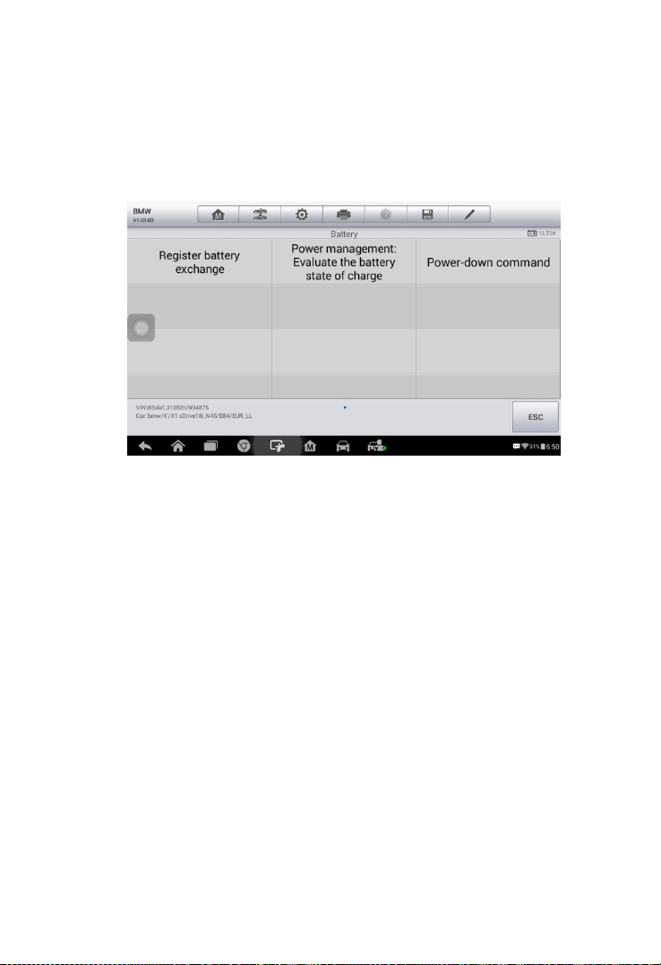
55
1. Tap the Service application button from the MaxiCOM Job Menu.
2. Tap BMS button and wait for the vehicle manufacturer screen. You
can tap VIN Scan or the vehicle make to acquire vehicle VIN
information and tap Yes to confirm. See Vehicle Identification on
page 21 for detail.
3. Tap Register battery exchange in the Battery function list. The
list may vary by test vehicle.
4. Tap on the desired function to complete. In our example, tap F1
Register battery replacement.
Figure 5- 9 Sample BMS Function List
Page 63
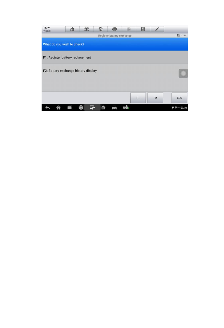
56
5. Read carefully the information on the screen and scroll through list
to view all functions.
There are four functions listed:
F1 Enter battery replacement: Same capacity
F2 Enter battery replacement: Higher/lower capacity
F3 Enter battery replacement: Changing from the normal
lead-acid battery (white housing) to AGM battery (black housing)
Figure 5- 10 Sample BMS Screen 1
Page 64

57
ESC End service function.
Take the second function as an example.
Figure 5- 12 Sample BMS Screen 3
6. Read carefully the information on the screen and tap Continue to
the next screen.
7. Follow the on-screen instructions to input the data matrix code of
the newly installed battery which should be on the label of the
battery. Tap OK to continue.
Figure 5- 11 Sample BMS Screen 2
Page 65

58
Figure 5- 13 Sample BMS Screen 4
8. When the battery exchange is successfully entered, tap Continue
to complete the operation.
Figure 5- 14 Sample BMS Screen 5
Steering Angle Sensor (SAS) Service
Steering Angle Sensor Calibration permanently stores the current
steering wheel position as the straight-ahead position in the steering
angle sensor EEPROM. Therefore, the front wheels and the steering
wheel must be set exactly to the straight-ahead position before calibration.
In addition, the vehicle identification number is also read from the
instrument cluster and stored permanently in the steering angle sensor
Page 66

59
EEPROM. On successful completion of calibration, the steering angle
sensor fault memory is automatically cleared.
Calibration must always be carried out after the following operations:
Steering wheel replacement
Steering angle sensor replacement
Any maintenance that involves opening the connector hub from the
steering angle sensor to the column
Any maintenance or repair work on the steering linkage, steering
gear or other related mechanism
Wheel alignment or wheel track adjustment
Accident repairs where damage to the steering angle sensor or
assembly, or any part of the steering system may have occurred
NOTE
1. AUTEL accepts no responsibility for any accident or injury arising
from servicing the SAS system. When interpreting DTCs retrieved
from the vehicle, always follow the manufacturer’s recommendation
for repair.
2. All software screens shown in this manual are examples, actual test
screens may vary for each test vehicle. Pay attention to the menu
titles and on-screen instructions to make correct option selections.
3. Before starting the procedure, make sure the vehicle has ESC button.
Look for the button on dash.
Using BMW as an example.
1. Tap the Service application button from the MaxiCOM Job Menu.
2. Tap SAS button and wait for the vehicle manufacturer screen. You
can tap VIN Scan or the vehicle make to acquire vehicle VIN
information and tap Yes to confirm. See Vehicle Identification on
page 21 for detail.
3. Tap the desired function in the SAS function list. The list may vary by
Page 67
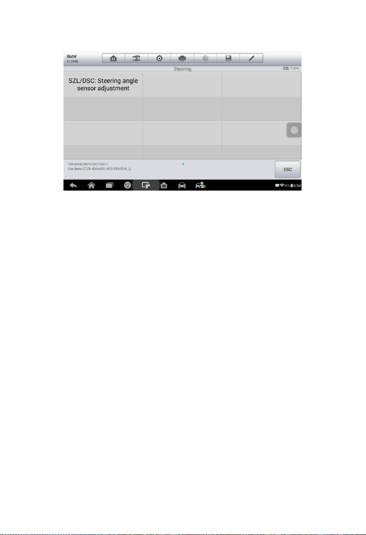
60
test vehicle.
Figure 5- 15 Sample SAS Function Menu
Steering Angle Sensor adjustment
This function allows users to perform steering angle sensor calibration
and clear records. The function options vary by vehicles.
1) Tap Steering Angle Sensor adjustment from the SAS function
menu to enter the function screen.
2) The steering angle must be calibrated after following jobs:
-Replacement of steering column switch cluster
-Encoding of DSC control unit
-Adjustment work on steering geometry
-Working on steering and/or front axle
Page 68

61
Tap continue to the next step.
Figure 5- 16 Sample SAS Function Screen 1
3) The run flat indicator must be additionally initialised after adjusting
the steering angle sensor on completion of the following work:
-Encoding of DSC control unit
-Replacement of DSC control unit
Tap continue to proceed.
Figure 5- 17 Sample SAS Function Screen 2
Page 69

62
4) Read the complete information carefully and tap Yes to the next step,
tap No to exit.
Figure 5- 18 Sample SAS Function Screen 3
5) Follow the step-by-step on-screen instruction to continue.
Figure 5- 19 Sample SAS Function Screen 4
6) Read the complete information carefully and tap Yes to end the test
module or tap No to continue.
Page 70

63
Figure 5- 20 Sample SAS Function Screen 5
7) Exactly set front wheels to straight-ahead position. The steering
wheel must be positioned horizontally. Tap Continue to the next
step.
Figure 5- 21 Sample SAS Function Screen 6
8) Read the attention carefully and tap Continue to the next step.
Page 71

64
Figure 5- 22 Sample SAS Function Screen 7
9) The adjustment procedure is started in this step, please wait until the
“Adjustment was successful” message displayed. Tap Continue to
proceed.
10) Confirm the degrees of the steering angle and then tap Yes to
continue.
Figure 5-23 Sample SAS Function Screen 8
Page 72
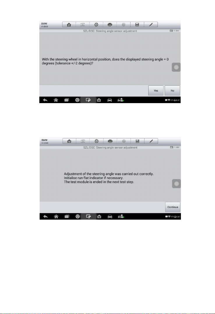
65
Figure 5- 24 Sample SAS Function Screen 9
11) Adjustment of the steering angle was carried out correctly.Tap
Continue to end the test module.
Figure 5- 25 Sample SAS Function Screen 10
Page 73

66
Diesel Particle Filter (DPF) Service
The Diesel Particle Filter (DPF) function manages DPF regeneration,
DPF component replacement teach-in and DPF teach-in after replacing
the engine control unit.
The ECM monitors driving style and selects a suitable time to employ
regeneration. Cars driven a lot at idling speed and low load will attempt to
regenerate earlier than cars driven more with high load and speed. In
order for regeneration to take place, a prolonged high exhaust
temperature must be obtained.
In the event of the car being driven in such a way that regeneration is not
possible, i.e., frequent short journeys, a diagnostic trouble code will
eventually be registered in addition to the DPF light and “Check Engine”
indicators displaying. A service regeneration can be requested in the
workshop, using the diagnostic tool.
Before performing a forced DPF regeneration using the tool, check the
following items:
The fuel light is not on.
No DPF-relevant faults are stored in system.
The vehicle has the correct spec engine oil.
The oil for diesel is not contaminated.
IMPORTANT
Before diagnosing a problem vehicle and attempting to perform an
emergency regeneration, it is important to obtain a full diagnostic log and
read out relevant measured value blocks.
NOTE
1. The DPF will not regenerate if the engine management light is on, or
there is a faulty EGR valve.
2. The ECU must be re-adapted when replacing the DPF and when
topping up the fuel additive Eolys.
3. If the vehicle needs to be driven in order to perform a DPF service, a
second person is needed for the function. One person should drive
Page 74

67
the vehicle while the other person observes the screen on the Tool.
Do not attempt to drive and observe the scan tool at the same time.
This is dangerous and puts your life and the lives of other motors and
pedestrians at risk.
1. Tap the Service application button from the MaxiCOM Job Menu.
2. DPF button and wait for the vehicle manufacturer screen. You can tap
VIN Scan or the vehicle make to acquire vehicle VIN information and
tap Yes to confirm. See Vehicle Identification on page 21 for detail.
3. Tap the desired function in the DPF function list. The list may vary by
test vehicle.
Figure 5- 26 Sample DPF Service Function Menu
4. Follow the step-by-step on-screen instruction to complete the service.
Using Diesel particulate filter:-Request regeneration as an example.
Diesel particulate filter:-Request regeneration
1. Tap Diesel particulate filter:-Request regeneration from the service
functions menu.
2. Read the Note carefully and tap Continue to the next step.
Page 75
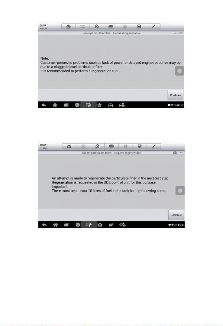
68
Figure 5- 27 Sample DPF Function Screen 1
3. A series of instruction screens display for users to perform the Request
regeneration step by step.
4. The particulate filter can only be regenerated by driving the vehicle and
it requires approximately 45 minutes.Tap Continue to the next step.
Figure 5- 28 Sample DPF Function Screen 2
Page 76

69
Figure 5- 29 Sample DPF Function Screen 3
5. The tool will display a function list menu as below. Press the
corresponding number button to perform the desired function.Tap F1 to
perform Request regeneration or tap ESC to end this procedure.
6. When perform successfully, a “ Regeneration was successfully
requested ” message will display on the screen.Tap Continue to the
next step.
Figure 5- 30 Sample DPF Function Screen 4
Page 77

70
Figure 5- 31 Sample DPF Function Screen 5
7. Switch off the ignition and tap Continue to the next step.
Figure 5- 32 Sample DPF Function Screen 6
8. Turn on ignition again and start engine.Read the notes on the screen
carefully and then tap Continue to the next step.
Page 78
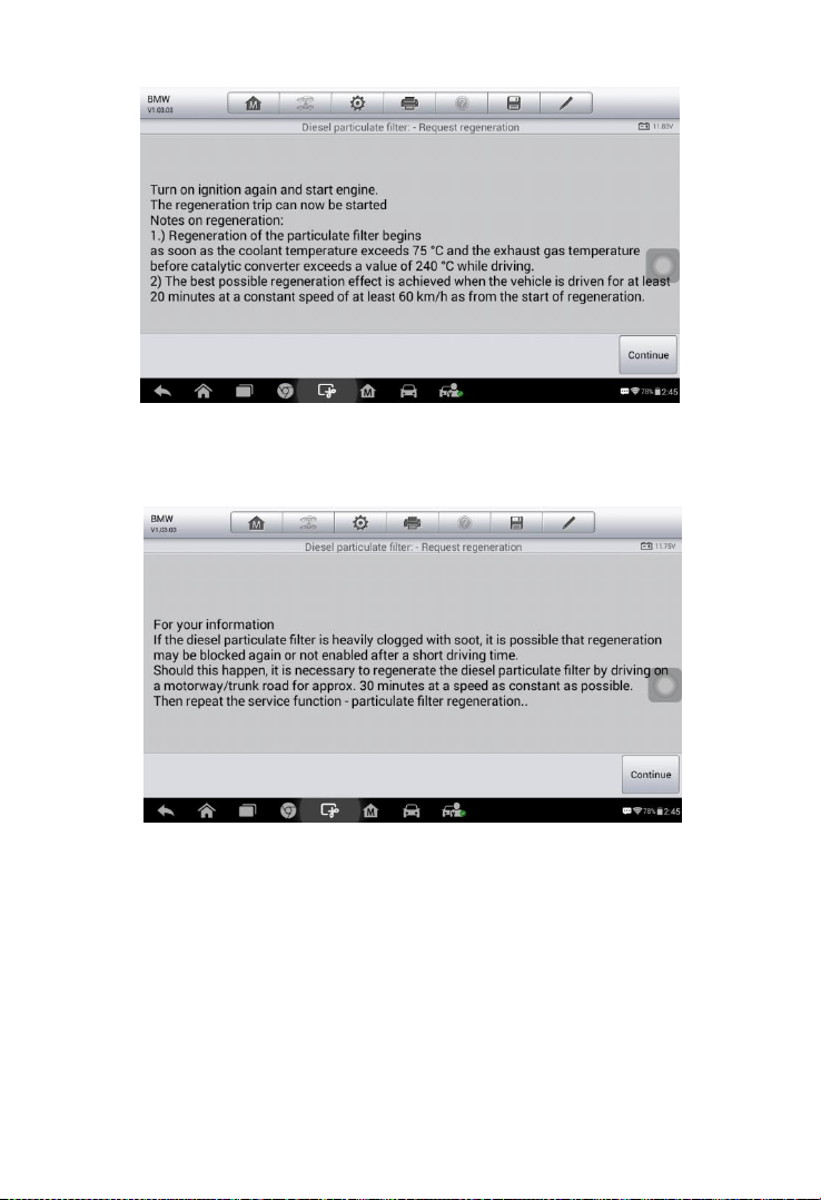
71
Figure 5- 33 Sample DPF Function Screen 7
9. Read the information carefully and then tap Continue to the next step.
10. The current regeneration status is shown in the following step.Read the
information carefully and then tap Continue to the next step.
Figure 5- 34 Sample DPF Function Screen 8
Page 79

72
Figure 5- 35 Sample DPF Function Screen 9
11. A series of instruction screens display for users to perform the particle
filter regeneration step by step. Follow the onscreen instructions and tap
Continue button until the tool displays the regeneration status as
below.
Figure 5- 36 Sample DPF Function Screen 10
12. Tap F1 to continue display the status of current regeneration or tap ESC
to exit.
Page 80

73
Figure 5- 37 Sample DPF Function Screen 10
Page 81

74
6 Data Manager
The Data Manager application is used to store, print, and review the
saved files. Most operations are controlled through the toolbar.
Selecting the Data Manager application opens the file system menu.
Different file types are sorted separately under different options, there are
five types of information files to be viewed or played back.
Operations
Data Manager Operations are based on toolbar controls. Details are
explained in the following sections.
Figure 6- 1 Sample Data Manager Main Screen
Page 82

75
Image Files
The Image section contains all captured screenshot images.
Figure 6- 2 Sample Image Screen
1. Toolbar Buttons – used to edit, print and delete the image files. See
the following table for detailed information.
2. Main Section – displays the stored images.
Table 6-1 Toolbar Buttons in Image Screen
Button
Name
Description
Back
Returns to the previous screen.
Enter Edit
Tap this button to display the editing
toolbar. Print, delete or view image
information.
Cancel
Tap this button to close the editing
toolbar or cancel file search.
Search
Quickly locates the image file by
entering the vehicle name, test path,
file name or file info.
Info
Tap this button to display the details.
Print
Tap this button to print the selected
image.
Page 83

76
Delete
Tap this button to delete the selected
image.
To edit image information
1. Select Data Manager application from the MaxiCOM Job Menu.
2. Select Image to access the image database.
3. Select an image to display in full screen.
4. Tap the screen to display the editing toolbar.
5. Tap the Info button to display image information.
6. Tap the Edit button on the top right corner of the window. The
editing screen displays.
7. Edit the image information by entering the new file name, and file
information.
8. Tap Done to save the information and exit, or tap Cancel to exit
without saving.
NOTE
The printer driver program must be installed in order for the tablet’s Wi-Fi
printer capabilities can be used.
To install the printer driver program
1. Please download the Maxi PC Suite from www.autel.com >
Support & Updates > Firmware & Downloads > UPDATE CLIENT,
and install to your windows-PC. The Maxi PC Suite consists of
Autel Printer, MaxiSys Pinter and PC Suite.
2. Double click on Setup.exe item.
3. Select the installation language and the printer driver installation
wizard will load momentarily.
4. Follow the wizard instructions on the screen and click Next to
continue.
5. Click on Install and the printer driver program will be installed onto
the computer.
6. Click on Finish to complete the installation procedure.
To delete selected images
1. Select Data Manager application from the MaxiCOM Job Menu.
Page 84

77
2. Select Image to access the JPG database.
3. Tap the Enter Edit button to display the editing toolbar.
4. Select the images that need to be deleted by tapping the thumbnail
images, the selected thumbnail displays a tick icon at the bottom
right corner.
5. Tap the Delete button, and then Delete Selected, then the
selected images will be deleted.
PDF Files
The PDF section stores and displays all saved data PDF files. Select a
PDF file from the database to display.
The standard Adobe Reader application is used for file viewing and
editing, please refer to the associated Adobe Reader manual for detailed
instructions.
Review Data
The Review Data section allows playback of the recorded data frames of
live data streams.
On the Review Data main screen, select a record file to playback.
Figure 6- 3 Sample Data Playback Screen
1. Drop-down Toolbar – tap the button at the top center of the screen to
Page 85

78
open the Drop-down Toolbar.
2. Main Section – displays the recorded data frames.
3. Navigation Toolbar – controls data playback.
Use the Navigation Toolbar buttons to playback the record data from
frame to frame.
Tap Back to exit data playback.
Apps Uninstall
This section manages the firmware applications installed on the
MaxiCOM Diagnostics System. Select this section to open a management
screen, on which you all the available vehicle diagnostic application can
be reviewed.
Tap on the vehicle manufacturer icon that you wish to delete. The
selected icon will display a blue check at the upper right corner. Tap the
Delete button on the top bar to delete the firmware from the system
database.
Data Logging
The Data Logging section allows you to launch Support platform directly
to view all records of all sent or unsent (saved) data loggings on the
diagnostic system. For more details, please refer to Data Logging on
Page 119.
Page 86

79
7 Settings
Tap the Settings button to adjust the default setting and view information
about the MaxiCOM system. There are seven options available for the
MaxiCOM system settings:
Unit
Language
Printing Setting
Notification Center
Auto Update
About
System Settings
This section describes the procedures to adjust the device’s system settings.
Unit
This option allows you to adjust the measurement unit for the diagnostic
system.
To adjust the unit setting
1. Tap the Settings application on the MaxiCOM Job Menu.
2. Tap the Unit option on the left column.
3. Select the appropriate measurement unit, Metric or English. A tick
icon will display to the right of the selected unit.
4. Tap the Home button on the top left corner to return to the
MaxiCOM Job Menu. Or select another setting option for system
Page 87

80
setup.
Figure 7- 1 Sample Unit Setting Screen
Language
This option allows you to adjust the display language for the MaxiCOM
system.
To adjust the language setting
1. Tap the Settings application on the MaxiCOM Job Menu.
2. Tap the Language option on the left column.
Figure 7- 2 Sample Language Setting Screen
3. Select the appropriate language. A check will display to the right of
the selected language.
Page 88

81
4. Tap the Home button on the top left corner to return to the
MaxiCOM Job Menu, or tap another setting to adjust.
Printing Setting
Configure this option to enable the tablet to print through a specified Wi-Fi
network connection.
To setup the printer connection
1. Tap the Settings application on the MaxiCOM Job Menu.
2. Tap the Printing Setting option on the left column.
3. Tap the Print via Network item to activate the printing function,
which enables the device to send files to the printer through the
networked PC via Wi-Fi connection.
4. Tap the Home button on the top left corner to return to the
MaxiCOM Job Menu, or tap another setting to adjust.
Figure 7- 3 Sample Printing Setting Screen
Printing via APP
MK808BT provides the most convenient printing method, printing via
APP.
To realize this function, please make sure a Wi-Fi printer is available and
then purchase a Wi-Fi printer APP and install it onto your tablet.
Page 89

82
By a simple click on the Print button of a saved file on the tablet, the file
will be printed automatically.
Printing via PC
If the Wi-Fi printer is not available, you can also use your windows-PC to
print the data on the tablet. Follow the instructions below to realize this
function.
To install the printer driver program to a computer
1. Download the Maxi PC Suite from www.autel.com and install to
your windows-PC.
2. Double click on Setup.exe item.
3. Select the installation language and the wizard will load
momentarily.
4. Follow the instructions on the screen and click Next to continue.
5. Click on Install and the printer driver program will be installed onto
the computer.
6. Click on Finish to complete the installation.
NOTE
The MaxiSys Printer runs automatically after the installation. The
computer, printer and the tablet must be connected to the same network.
To perform printing through the computer
1. Run the MaxiSys Printer program on the computer.
2. Click Test Print to make sure the printer is working successfully.
3. Tap the Print button on the toolbar. A temporary document will be
created and sent to the computer for printing and the received
document automatically when the Auto Print option is selected.
4. Tap the Print button on the toolbar of the tablet. A test document
will be sent to the computer.
If the Auto Print option in the MaxiSys Printer is selected, the
MaxiSys Printer will print the received document
automatically.
Page 90

83
If the Auto Print option is not selected, click Open PDF File
button to view all the temporary files. Select the file(s) to
print and click Print.
Notification Center
This option allows you to turn the Notification Center function on or off.
The Notification Center function configures the MaxiCOM tablet to receive
regular on-line messages from the server for system update notifications
or other service information via the Internet. It is highly recommended to
keep this function ON all the time, to ensure notifications of updates are
received. Internet access is required for receiving on-line messages.
To enable the Notification Center function
1. Tap the Settings application on the MaxiCOM Job Menu.
2. Tap the Notification Center option on the left column.
3. Tap the ON/OFF button to enable or disable the Notifications
function. If the function is enabled the button turns blue, or if
disabled the button turns gray.
Figure 7- 4 Sample Notification Screen
4. Tap the Home button on the top left corner to return to the
MaxiCOM Job Menu or choose another setting to adjust.
When the Notification Center function is turned on, and new messages
are received by the MaxiCOM device, a notification message displays on
the MaxiCOM Job Menu. Press on the message bar and drag it down,
Page 91
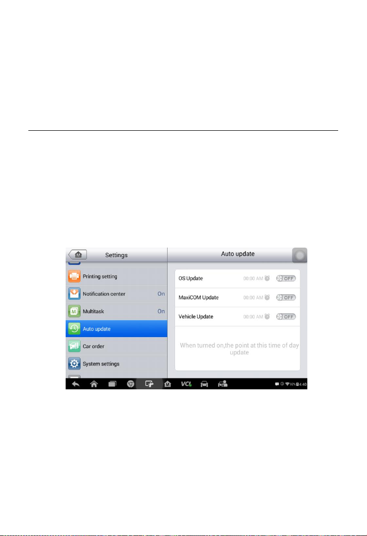
84
and the received messages are shown in the list. Swipe up or down to
view if the message list populates additional screen.
Tap a specific message to launch the corresponding application. For
example, tap on an Update notification message and the Update
application will launch.
Auto Update
The Auto Update allows the tool to automatically update the OS, the
MaxiCOM system, and the Vehicle coverage software. Each can be
configured to update automatically at specified times. Tap the ON/OFF
button and set the desired automatic update time.
To set auto system or vehicle update
1. Tap the Settings application on the MaxiCOM Job Menu.
2. Tap the Auto Update option on the left column. The three auto
update items display on the right.
Figure 7- 5 Sample Auto Update Screen
3. Select the update type to schedule. Toggle the button to ON.
4. To set download time, use the + and – button or tap on the
Page 92

85
numbers and the manual input screen will display. Tap Done to
complete the time setting.
Figure 7- 6 Sample Set Time Screen
NOTE
The tool must be connected to the Internet at the time download is
scheduled.
System Settings
Access the Android system setting interface to adjust background system
settings including wireless and network settings, sound and display
screen settings and system security settings.
To enable the App Switcher function
1. Tap the Settings application on the MaxiCOM Job Menu.
2. Tap the System settings option on the left column.
Page 93
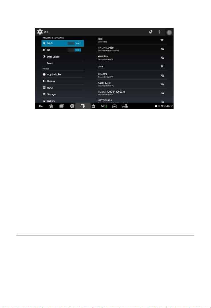
86
Figure 7- 7 Sample System Settings Screen
3. Tap the App Switcher option on the left column.
4. Check the box beside “Always show the App Switcher” on the
right side of the screen, then the App Switcher icon will display.
Short pressing the App Switcher icon opens a control panel:
Tap a specific app shortcut button to access selected application
screen.
Long press a specific app shortcut button to display the app menu.
The shortcut can be altered here.
Press and drag the App Switcher icon to alter the icon position on
the screen.
Refer to Android documentation for additional information about Android
system settings.
About
About displays information regarding the MaxiCOM diagnostic device
including the product name, version, hardware, and serial number.
To check the MaxiCOM product information in About
1. Tap the Settings application on the MaxiCOM Job Menu.
2. Tap the About option on the left column. The product information
screen displays on the right.
Page 94
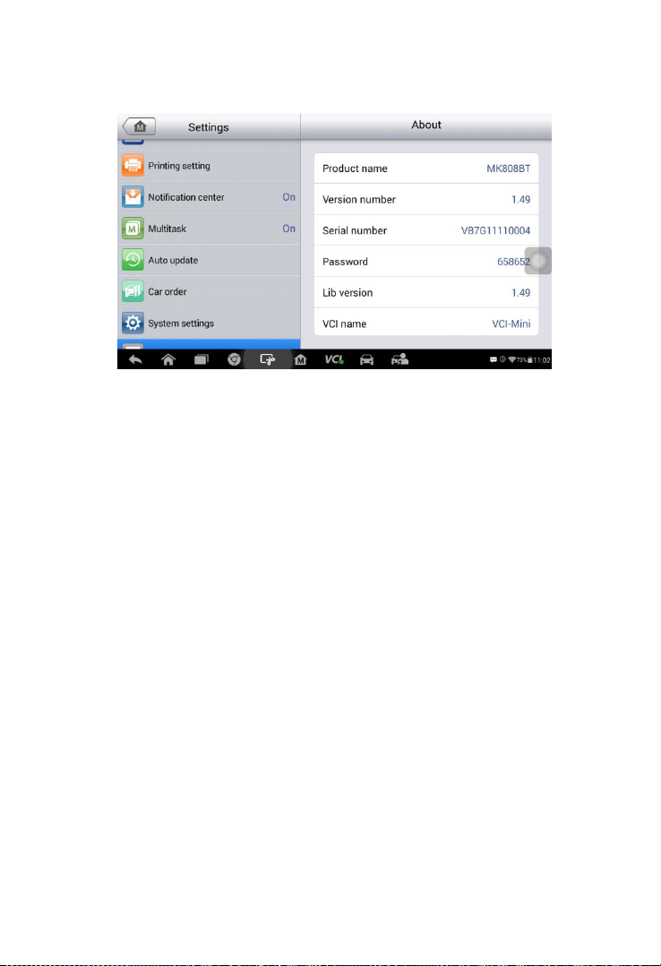
87
3. Tap the Home button on the top left corner to return to the
MaxiCOM Job Menu or select another setting to adjust.
Figure 7- 8 Sample About Screen
Page 95

88
8 Update
This chapter describes the update operation for both the MK808BT tablet
and the MaxiVCI Mini. The software and firmware updates of the tablet
can be completed on the tablet via Internet, while the updates for MaxiVCI
Mini can be completed either via the connection with the tablet or via the
connection with a PC.
Tablet Update
The Update application on the tablet downloads the latest released
software. The updates improve the MaxiCOM applications’ capabilities,
typically by adding new tests, new model coverage or by adding
enhanced applications.
Software Update
The tablet automatically searches for available updates for all of the
MaxiCOM software when it is connected to the Internet. Any updates that
are found can be downloaded and installed on the device. This section
describes update procedures in the MaxiCOM System. A notification
message displays if an update is available when the Notifications Center
function is enabled in the Settings application (See Notification Center
page 81 for details).
Page 96

89
Figure 8- 1 Sample Update Screen
1. Navigation and Controls
Home Button – returns to the MaxiCOM Job Menu.
Update All – updates all available updates.
Diagnostics Tab – displays all available vehicle diagnostic
software.
Search Bar – search specific update item by inputting the file name,
for example: enter a vehicle manufacturer.
2. Status Bar
Left Side – displays the MaxiCOM device model information and
serial number.
Right Side – displays an update progress bar indicating the
completion status.
3. Main Section
Left Column – displays vehicle buttons and update software
version information; tap the About button to display a function
list with additional software update details.
Middle Column – displays a brief introduction about the new
changes to the software operation or capabilities. Tap
○
i
button to open an information screen to view more details, and
Page 97

90
tap the dim area around to close the window.
Right Column – according to the operation status of each software
item, the button displays differently.
a) Tap Update to update the selected item.
b) Tap Pause to suspend the updating procedure.
c) Tap Continue to go on updating the suspended update.
Firmware Update
No separate update button exists to update tablet’s firmware. The
firmware update package will be downloaded together with the software
package. An update firmware message will display.
MaxiVCI Mini Update
Update via Display Tablet
Before updating the VCI software, ensure the tablet’s connection to the
Internet is stable.
To update the MaxiVCI Mini software
1. Power on the tablet.
2. Using a USB cable, connect the MaxiVCI Mini to the tablet.
3. Tap the VCI Manager application on the MaxiCOM Job Menu of
the tablet.
4. Select Update from the connection mode list.
5. The current version and the latest version of the VCI software will
be displayed after a few seconds. Click Update Now to update
the VCI software if available.
Update via PC
1. Down the Maxi PC Suite from www.autel.com > Support & Updates >
Firmware Downloads > Update Client, and install it onto your
windows-PC.
2. Using a USB cable, connect the MaxiVCI Mini to a PC.
Page 98

91
3. Launch the PC Suite on the PC which is installed after the installation
of Maxi PC Suite and click MaxiVCI Mini icon in the Device Selection
window.
4. The PC will automatically recognize the MaxiVCI Mini.
5. Click Update to complete the update if an update is available.
Page 99

92
9 VCI Manager
This application pairs the tablet with the MaxiVCI Mini, checks the
communication status and update the VCI software.
Figure 9- 1 Sample VCI Manager Screen
1. Connection Mode – there are three connection modes available for
selection. The connection state is displayed alongside.
BT Paring – when paired to a wireless device, the connection state
displays as Paired; otherwise it displays as Unpaired.
Update (for VCI software only) – when the MaxiCOM tablet and the
MaxiVCI Mini are connected by a USB cable, this function is
used to update VCI software via Internet.
2. BT Setting
The BT Setting screen displays the types and product serial numbers
for all the devices available for pairing. Tap a required device to start
pairing. The BT status icon displayed to the left of the device name
indicates the received signal strength.
BT Pairing
The MaxiVCI Mini needs to be connected to a vehicle, so that it is
powered during the synchronization procedure. Ensure the tablet has
sufficient battery life or is connected to an external power supply.
Page 100

93
To pair the MaxiVCI Mini with the Tablet
1. Power on the tablet.
2. Insert the 16-pin vehicle data connector of the MaxiVCI Mini to the
vehicle data link connector (DLC).
3. Tap the VCI Manager application on the MaxiCOM Job Menu of
the tablet.
4. Select BT from the connection mode list.
5. Tap the Scan button at the top right corner. Now the device starts
searching for available pairing units.
6. The device name may display as Maxi suffixed with a serial
number. Select the appropriate device for pairing.
7. When paring is successfully done, the connection status displayed
to the right of the device name is shown as Paired.
8. Once paired, the VCI button on the system Navigation bar at the
Connection LED on the MaxiVCI Mini illuminates solid blue. This
signifies that the tablet is connected to the MaxiVCI Mini, and is
ready to perform vehicle diagnosis.
9. Tap the paired device again to unpair it.
10. Tap the Home button on the top left to return to the MaxiCOM
Job Menu.
NOTE
A MaxiVCI Mini can be paired to only one tablet at a time, and once it’s
paired, the device will not be discoverable to other devices.
Update
Please refer to Update via Display Tablet on page 89 for details.
Programmer Update
Coming soon.
 Loading...