

Page 1

Table of Contents
1. Safety Precautions and Warnings......................1
2. Using the Auto Computer...................................2
2.1 Tool Descriptions ......................................2
2.2 Specifications.............................................3
2.3 Accessories.................................................3
2.4 Navigation Characters..............................3
2.5 Connecting to the Vehicle.........................4
2.6 Setup...........................................................6
2.7 Fill-up.......................................................12
2.8 Speed ........................................................14
2.9 Tool Information.....................................16
3. Trip Computer...................................................17
4. Gauges ................................................................19
5. Scan Tool............................................................20
5.1 Reading and Erasing Codes...................20
5.2 Retrieving I/M Readiness Status ...........21
5.3 Reading Freeze Frame Data ..................22
5.4 Viewing VIN Number.............................22
6. Vehicle Black Box..............................................23
7. Warranty and Service.......................................25
7.1 Limited One Year Warranty .................25
7.2 Service Procedures..................................25
Page 2

1
1. Safety Precautions and Warnings
To prevent personal injury or damage to vehicles and/or the
auto computer, read this instruction manual first and observe
the following safety precautions at a minimum whenever
working on a vehicle:
z Always keep attentive while driving.
z DO NOT try to make any adjustments while driving.
z DO NOT mount the auto computer in a position which can
obstruct the view of the driver.
z DO NOT mount the auto computer in a manner which could
cause it to be propelled through the vehicle during an accident
causing injury, such as over or near an airbag.
z DO NOT route the cable in a manner which would interfere
with the operation of the vehicle controls.
z Keep the auto computer dry, clean, free from oil/water or
grease. Use a mild detergent on a clean cloth to clean the
outside of the auto computer, when necessary.
Page 3
2. Using the Auto Computer
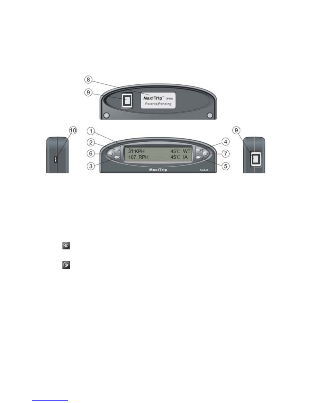
2.1 Tool Descriptions
○
1
LCD Display – Displays retrieved data.
○
2○3○4○5
Menu Selection Buttons -- When there is ► or ◄ icon
on the screen next to the button, press it to do what is displayed next
to it or to change to next available items. When viewing trip
information or gauge readings, the ► or ◄icon may not show.
○
6
Button -- Returns to previous screen, exit a menu or wake up
the tool from sleep mode.
○
7
Button -- Moves to next screen; it is also used to enter time
setup screen, and to reset CURRENT and VBB (Vehicle Black Box)
data.
○
8
Rear Label -- Provides model number of products.
○
9
OBDII Connector Port -- Connects the tool to vehicle’s DLC
with the OBDII cable supplied.
○
10
USB Port -- Connects the tool to a computer with the USB cable
supplied to update the tool.
2
Page 4

2.2 Specifications
1) Display: Backlit, 2 lines * 16 character display
2) Operating Temperature: 0 to 60°C (32 to 140 F°)
3) Storage Temperature: -20 to 70°C (-4 to 158 F°)
4) Power: 8 to 16 volts provided via vehicle battery
5) Dimensions:
Length Width Height
140 mm (5.51”)*43.6 mm (1.72”)*26.6 mm (1.05”)
6) NW: 0.2kg (0.44lbs) GW: 0.5kg(1.11lb)
2.3 Accessories
1) User’s manual -- Instructions on tool operations
2) OBD2 cable -- Provides power to tool and communicates
between the tool and vehicle.
3) USB cable -- Connects the tool to a computer for software
updates.
4) CD software -- Contains update tool, DTC lookup software
and etc.
5) Sticker -- Used to attach the tool to the position you have
chosen in your vehicle.
2.4 Navigation Characters
Characters used to help navigate the auto computer are:
1) “►or◄” -- Indicates the button next to it can be used and
presses it to do what is displayed next to it.
2) “
or ”-- Indicates more information is available on
previous/next screens.
3) “Pd” -- Identifies a pending code when viewing DTCs.
4) “←”-- Moves to previous digit.
5) “→”-- Moves to next digit; Indicates an option is selected.
6) “+”-- Increase digit value.
7) “-”-- Decrease digit value.
8) “∮” -- Indicates average speed and fuel economy.
9) “
” -- Indicates fuel volume.
10) “---” -- Indicates invalid data or an item is not supported.
3
Page 5
2.5 Connecting to the Vehicle
Follow steps below to connect the tool to the vehicle:
1) Connect the OBD II cable to the tool.
2) Place the tool to the position you have chosen.
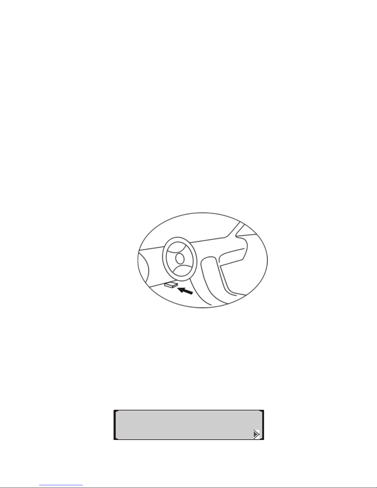
3) Locate DLC on vehicle.
• The DLC is usually located 12 inches from the center of the
instrument panel (dash), under or around the driver’s side for
most vehicles. If Data Link Connector is not located under
dashboard, a label should be there telling location. For some
Asian and European vehicles, the DLC is located behind the
ashtray and the ashtray must be removed to access the
connector. A plastic DLC cover may be found for some
vehicles and you need to remove it before plugging the OBD2
cable. If the DLC cannot be found, refer to the vehicle’s service
manual for the location.
4) Plug OBD II cable to the vehicle’s DLC.
5) Turn the ignition on. Engine can be off or running.
6) The auto computer starts to communicate with the vehicle.
If the vehicle is not OBDII compliant, a “Not Support”
message shows, and the auto computer goes to VIEW
MODE after 2 seconds. In VIEW MODE you are
allowed to view trip information and perform setups
only.
View Mode
◄
T
RIP SETUP
4
Page 6
If the auto computer fails to communicate with the
vehicle’s ECU (Engine Control Unit), a “Link Error”
message shows as below:
Link Error!
◄ AGAIN EXIT►
Use the button next to AGAIN to try to connect to the
vehicle, and the tool re-attempts to communicate with
the ECU. If there is still no communication between
them, a “CHECK MANUAL” message comes up
prompting you to refer to user’s manual of the tool for
troubleshooting tips.
Follow steps below to troubleshoot it:
9 Verify that the ignition is ON;
9 Check if the OBD II connector is securely connected
to the vehicle’s DLC;
9 Verify that the vehicle is OBD2 compliant;
9 Turn the ignition off and wait for about 10 seconds.
Turn the ignition back to on and repeat the procedure
from step 5.
9 If the auto computer still fails to communicate with
the ECU, contact the manufacturer.
Or press the button next to EXIT to enter VIEW MODE .
The auto computer keeps trying to connect to the
control module in VIEW MODE till communication is
established.
View Mode
◄
T
RIP SETUP
If the engine is off for about 20 seconds or there is no
communication between the tool and the vehicle for
about 20 seconds the trip computer automatically goes
to SLEEP mode. To wake up the tool from SLEEP
mode, press
.
7) When communication is established, it shows the HOME
screen.
5
Page 7
◄TRIP GAUGE►
◄SCAN SETUP
z The HOME screen is defaulted to display 4 menu
options as shown in the figure above. It can be set to
show the CURRENT trip information also. HOME
screen hereafter in the manual refers to the default
setting.
2.6 Setup
The auto computer allows you to make following adjustments and
settings:
1) Fuel: Selects the fuel type your vehicle uses.
2) Engine: Sets up engine size.
3) Size: Selects tank size of the vehicle
4) Unit: Changes unit of measure.
5) Time: Adjusts time displayed by the auto computer.
6) Rate: Sets sampling and recording rate.
7) Display: Sets contrast, display mode and home screen of the
tool.
8) Default: Resets all units, engine displacement, engine type,
tank size, gauge settings, trip data and screen settings to
manufacturer defaults. But VBB will not be cleared.
• The auto computer uses flash memory to save settings, so they
will not be lost when the tool is disconnected from the vehicle.
To enter setup menu
1) Press the button next to SETUP to perform various setups.
◄TRIP GAUGE►
◄SCAN SETUP
A. Vehicle Setup
NOTE: In order to get accurate data of fuel economy, distance
to empty, time to empty and etc., always perform vehicle setups
if it is the first time to use the auto computer in a vehicle, it is
6
Page 8
used in another vehicle and then return it back to this one, or it
is reset to factory defaults.
Fuel
1) Press the button next to FUEL to enter fuel setup menu.
FUEL SIZE►
◄ENGINE UNITS►
2) Use the button on the upper left or upper right to select the
fuel type your vehicle uses.
◄ GAS ►
Fuel Type SAVE►
3) Press SAVE button and an “→” icon appears on the screen
indicating the type is selected.
◄
→HYBRID ►
Fuel Type SAVE►
• DIESELa and DIESELb do not refer to different types of
diesel fuel. They only affect the way fuel consumption is
computed and are selected based on the way the vehicle
computer reports its sensor information. Most diesel vehicles
use DIESELa. Do the following to determine which your
diesel vehicle uses: set engine size
→
choose DIESELa
→
warm up the engine and idle in neutral or park→select
TRIP->CURRENT->GPH and note the GPH reading
→
step
on the accelerator pedal. If the GPH reading increases, you
have a DIESELa vehicle. If the GPH drops or stays the same,
you have a DIESELb vehicle.
Tank Size
• The limits of tank size are 0 -150L (0 - 39G).
1) Press the button next to SIZE to set the tank size of your
vehicle.
7
Page 9
FUEL SIZE►
◄ENGINE UNITS►
2) Use the button next to “-” or “+” to change the tank size, and
press SAVE button to save, and return to previous menu.
- 56 LITERS +
Tank Size SAVE ►
Engine
• The limits of engine size are 0-9.9L (0-2.6G)
1) Press the button next to ENGINE.
FUEL SIZE►
◄ENGINE UNITS►
2) Use the button next to “-” or “+” to change engine size, and
press SAVE button.
- 2.4 LITRES +
ENGINE SAVE►
Units of Measure
1) Press the button next to UNITS to change units of measure.
FUEL SIZE►
◄ENGINE UNITS►
2) Use the upper left or upper right button to change between
metric and English unit of measure, and press SAVE.
◄ METRIC ►
Units SAVE►
8
Page 10
B. Tool Setup
Time
1) Press
from home screen.
• If the home screen is set to display information of current trip,
use
first and then press button.
2) Press the button next to TIME.
3) Press
to enter time adjustment screen.
19:36:26
2007/11/26
- 19:36:26 +
← 2007/11/26 →
VBB TIME►
◄FILLUP RATE►
4) Use the button next to “←” or “→” to select a digit, and then
use the button next to “-” or “+” to increase or decrease
value.
5) Press
to finish and save the setup, and a “SET OK”
message show. If you do not wish to save the adjustment
press to exit.
Rate
1) Press
from home screen.
VBB TIME►
◄FILLUP RATE►
2) Press the button next to RATE.
SMP RATE
◄REC RATE
3) To change data update rate, press the button next to SMP
RATE.
9
Page 11
◄ NORMAL ►
SMP Rate SAVE►
4) Use the upper left or upper right button to select a sampling
rate between “NORMAL” and “SLOW”, and press SAVE
button.
• NORMAL is the factory default rate. If this causes some
updates to be skipped or irregular operation, SLOW should
be used. NORMAL can be used in PWM and all the CAN
vehicles, and SLOW should be used in VPW, ISO and KWP
vehicles. Observe the protocol type of your vehicle detected
by the auto computer in the screen when it links to the vehicle.
5) To change recording rate, press the button next to REC
RATE.
SMP RATE
◄REC RATE
6) Use the upper left and upper right button to change, and press
SAVE button to save the setup.
◄ 3 Seconds ►
REC Rate SAVE►
• When the recording rate is set to “2 Seconds” the auto
computer is able to record up to 150 hours of driving data;
when it is set to “3 Seconds” it can record a maximum of 300
hours of data.
Display
1) Press
from home screen twice.
SPEED DISPLAY►
◄ABOUT DEFAULT►
2) Press the button next to DISPLAY.
10
Page 12
MODE HOME►
◄CONTRAST
3) To change the display of trip items, press the button next to
MODE.
◄ 2 Items ►
Trip Mode SAVE►
4) Use the upper left or upper right button to change between “2
Items” and “4 Items”, and press SAVE.
z “X Items” indicates how many items are displayed in
one screen when viewing trip information.
5) To change the display of home screen, press the button next
to HOME.
MODE HOME►
◄CONTRAST
6) Use the upper left or upper right button to select MENU to
show 4 menu options in one screen, or to set the screen to
show current trip information by selecting CURRENT TRIP,
and press SAVE.
• It is advisable to set the home screen to show current trip
information if you use the trip computer in one vehicle only.
• If the trip computer is set to show information of current trip,
use
to exit current trip display before viewing other
information, or performing setups.
7) To change the contrast of display, press the button next to
CONTRAST.
MODE HOME►
◄CONTRAST
8) Use the button next to “-” or “+” to adjust, and press SAVE.
11
Page 13
◄ 3 ►
Contrast SAVE►
Default
1) To reset the auto computer to factory defaults, press from
home screen twice.
SPEED DISPLAY►
◄ABOUT DEFAULT►
2) Press the button next to DEFAULT.
Are you sure?
◄YES NO►
3) Press YES to reset the tool to factory defaults, or press NO to
exit.
2.7 Fill-up
NOTE: In order to get more accurate fuel consumption
readings, and to get valid TANK information, use the FILLUP
function every time when your vehicle is refueled. Make sure
the tank size and fuel types are properly set before useing this
function.
1) Fill the tank in gas station and let the pump shut off
automatically.
2) Press the button next to FILLUP, and press DONE without
adjusting the indicated fuel on the first fill-up after connecting
the auto computer to the vehicle.
3) Drive your vehicle normally with the auto computer
connected.
4) When the tank is around 1/4 full, drive to the same gas station,
use the same fuel pump, fill up the tank at the same rate and
let it shut off automatically.
5) Press the button next to FILLUP.
12
Page 14
VBB TIME►
◄FILLUP RATE►
6) Use the button next to “-” or “+” to change the adjustment
factor in 0.1% step till the number to the right of “→”agrees
with the value reported by the fuel dispenser.
- 1.2% LITRE +
15.0 → 16.8 DONE►
z The number to the left of “→” is the amount of fuel the
auto computer believes was used since last fill-up; the
number to the right of “→” is the amount of fuel
reported by fuel dispenser. Before changing the
adjustment factor, these two numbers are the same.
7) Press DONE to finish the adjustment and the fuel economy
will be immediately affected by the adjustment.
• Record the adjustment factor for your vehicle if you use it in
another vehicle and then return it back to this one, so you can
later adjust it back to the recorded one by doing the following:
use FILLUP with engine off
→
press DONE to clear TANK
data
→
when refuel, press FILLUP again→use “-” or “+” to
enter the adjustment factor manually.
• It is advisable to use the FILLUP function immediately after
refuel. When you forget to do so, you can also change the
adjustment factor directly if less than 1 gallon/liter has been
used since the previous fill-up sequence was done.
IMPORTANT: Do not rely on a low reading of DISTANCE TO
EMPTY to decide when the next fill-up should be, as the
absolute accuracy is limited by following variables:
λ Different shutoff levels of fuel pumps;
λ Different tilt of the vehicle at the fuel pump due to
ground slope or vehicle loading;
λ Different temperature of the fuel (changes density –
best to refill in the morning when the fuel is colder);
13
Page 15

λ Variations in vehicle sensors due to temperature and
time;
λ Pump accuracy limits.
2.8 Speed
A. To Do Speed Correction
Speed and distance adjustments are used to compensate for
changes in tire size, gears, tire wear, etc...
There are several means of speed correction:
A. For tire changes, use the formula below to compute an
approximate percentage.
Approximate percentage=
14
( -1) x 100%
Diameter of
Original Tire
Diameter of
New
tir
e
For example, if the diameter of the of original tire is 30 inches, and
that of the new tire is 40 inches, the percentage should be
( -1) x 100% =33%
40
30
So setting the value to 33% will compensate for the tire change.
B. For gear changes, use the formula below to compute an
approximate percentage.
Approximate percentage =
(1- ) x 100%
Old ratio
New ratio
For example, if the old ratio is 2.75, the new one is 3.25, the
percentage should be
(1- ) x 100%= -18%
3.25
2.75
So setting the value to -18% will compensate for the gear change.
Page 16
1) Press the button next to SPEED.
SPEED DISPLAY►
◄ABOUT DEFAULT►
2) Use the button next to ADJUST to enter speed correction
screen.
ADJUST
◄LIMITED
3) Use the button next to “-” or “+” to adjust in 1% step till the
adjustment factor reaches the computed percentage, and press
SAVE button.
- 11% +
100 →111 SAVE►
z The number to the left of “→” is the speed reported by
the vehicle. The number to the right of “
→” is the speed
which is displayed by the auto computer by applying
this correction.
C. To set the speed accurately, you need a handheld GPS. One
person observes the speed displayed on the GPS and adjusts
the percentage till the number to the right of “
→” agrees with
the speed indicated on the GPS while the other is driving. Set
both the GPS and the auto computer to display the same unit
of speed (KPH or MPH) to make more accurate adjustments.
D. Drive at an auto computer indicated speed of 60 MPH and
measure the time between mile marker posts on a highway.
For every second more than 60 it takes to go 1 mile, subtract
1% from the adjustment with the upper left button. Repeat this
a few times until it takes 60 seconds plus or minus a second to
go 1 mile.
• The adjustment does not affect the vehicle speedometer or
odometer readings, but the auto computer indicated speed
and distance only.
15
Page 17
B. To Set Speed Limit
To make the TIME OVER SPEED data in VBB valid, you need
to set a speed limit for the vehicle being tested.
1) Use the button next to LIMITED.
ADJUST
◄LIMITED
2) Use the button next to “-” or “+” to adjust in 1KPH(MPH)
step or use the button next to “+10” to change in 10
KPH(MPH) step till the limit reaches your desired one and
press SAVE button.
- 80KPH +
◄ +10 SAVE►
2.9 Tool Information
This function is used to view software version of the tool and
look up unit conversions between metric and English unit of
measure.
1) Press
twice from home screen.
SPEED DISPLAY►
◄ABOUT DEFAULT►
2) Use the button next to ABOUT.
VERSION
◄CONVERSION
3) Press the button next to VERSION to view software version
on screen.
Version 1. 0 2008
Autel Maxitrip
4) Press
to exit.
16
Page 18
5) To lookup unit conversions, press the button next to
CONVERSION.
VERSION
◄CONVERSION
6) View the conversion results on screen, and Press
to exit.
1 Mile=1.61Km
1Km=0.621Mile
3. Trip Computer
A trip is a process that driving data is recorded. The auto
computer automatically records trip data when the engine is
started. If the engine is off for more than 30 minutes, it starts
recording a new trip.
The auto computer records information about CURRENT,
TODAY, TOTAL and TANK trip data.
CURRENT records trip data since engine is started and it is
able to save up to 24 hours of data. CURRENT data can be
cleared by holding
for about 3 seconds and then pressing
YES.
TODAY records driving data in one day and it saves a
maximum of 24 hours of data. The auto computer starts a new
trip recording at 00:00.
TOTAL saves up to 100 hours of data. The TOTAL
information includes data recorded since last time the tool is
reset. When it records more than 100 hours of data, the driving
distance exceeds 9,999km (6,213 miles) or the fuel used is over
999L (263.85gal), TOTAL data will be cleared automatically,
and it starts recording a new trip.
TANK saves trip data since last fill-up.
Displayed items are as follow:
¾ KPH (MPH): Current vehicle speed
¾ L (GAL): Fuel used of current trip
17
¾ LK∮ (MG∮): Average fuel economy per 100 kilometer/mile
Page 19
¾ LHK (MPG): Fuel economy per 100 kilometer/mile
18
en
¾ XX:XX: Time driven
¾ KM (MI): Distance driv
¾ KM
(MI ): Distance remaining before tank is empty
N
¾ KH∮(MH∮): Average speed
¾ KPH (MPH): Maximum speed
OTE: When vehicle speed is 0, LHK (MPG), Fuel economy
per 100 kilometer/mile, is automatically changed to LPH
(GPH), fuel used per hour.
TANK data shows the following items:
¾ L (GAL): Fuel used since last fill-up
¾ L
(GAL ): Fuel remaining
M last fi
¾ K (MI): Distance driven since ll-up
¾ KM
(MI ): Distance remaining before ta
¾ X m
nk is empty
XX: X: Ti e driven since last fill-up
¾ XX:XX
: Time remaining before tank is empty
¾ LK∮(G ∮): Average fuel economy per 100 kiloK meter/mile
¾ LH∮ (GH∮): Average fuel economy per hour.
IMPORTANT: DO NOT disconnect the auto computer from the
1)
vehicle while driving; otherwise trip data may be lost or
inaccurate.
Use any of the menu selection buttons to select a set of trip
data to view.
CUR
2) View de e any of the tailed trip information on the screen. Us
menu selection buttons to view information of next available
items, or use
to view additional data on next screen(s), or
press
to exit.
RENT TODAY►
◄
20.5 LK∮
TANK TOTAL►
0.0 LPH
0.8L 200 KM
z If seconds,
the trip computer records them automatically and it
the selected items are displayed for about 12
Page 20
19
3) When
shows these items directly when viewing trip
information next time.
viewing current trip information, hold
button for
3 seconds to reset current
about trip data manually.
YES to clear data of current trip or use th
to e
Reset CURRENT?
4) Press e button next to
NO
4. Gauges
mputer can be configured to measure and monitor
different sets of information simultaneously,
mperature
d absolute pressure
cylinder
GAUGES from home screen.
xit.
• TODAY and TOTAL information will not be reset by doing
this.
The auto co
up to four
providing real-time engine performance analysis to allow you
to adjust driving behavior and improve fuel economy.
Displayed items are as follows:
¾ KPH (MPH): Vehicle speed
¾ CWT (FWT): Engine coolant te
¾ RPM: Engine RPM
¾ CIA (FIA): Intake air temperature
¾ MAP: Intake manifol
¾ LOD: Calculated LOD Value
¾ TPS: Absolute Throttle Position
¾ FPR: Fuel Rail pressure
¾ IGN: Ignition timing spark for #1
¾ VLT: Voltage of battery
¾ LP: Fuel system 1 status
1) Press the button next to
ew 2) Vi
◄YES NO►
◄ GAUGES ► TRIP
◄SCAN SETUP
currently selected gauges on screen.
Page 21
e th
31 KPH 45 WT℃
107 RPM 45 IA℃
20
3) Us e button next to a gauge or use
change to next
z
z
5. Scan Tool
Erasing Codes
art scanning.
to
available gauges until they return to the arting ones.
The information available varies from vehicle to vehicle.
st
If the information is not available for a certain gauge, or
a reading is invalid, the trip computer shows “---”.
If the selected gauges are displayed for about 12
seconds, the trip computer records them automatically,
and shows these gauges directly when viewing gauge
readings next time.
5.1 Reading and
1) Press the button next to SCAN to st
Press the button next to DTC to view codes.
◄TRIP GAUGES ►
◄SCAN SETUP
2)
If
DTC I/M►
◄FRZD VIN►
z ow “No Codes
3) If mor e code is detected, use the lower left or lower
no codes were found, the screen will sh
Found!”
e than on
right button to view previous or next codes.
“
P1630 ERASE►
z e of currently
z
x/x” in the screen indicates sequenc
displayed code and the total number of retrieved DTCs.
If a pending code is detected, a “Pd” icon appears.
◄
P2126 Pd ERASE►
◄ 5/6
1/6 ►
Page 22
ase
codes, use the button next to ERASE4) To er .
rni
P0238 Pd ERASE►
21
5) A wa onfirmation. ng message comes up asking for your c
u w
6) If yo des are cleared
7)
AU
ish to erase codes, press YES. When co
successfully, an “Erase Done!” message comes up and the tool
rescans the vehicle to verify. If codes are not cleared, a
“Failed!” message appears.
If you do not wish to erase code, press NO button to exit, and
a “Canceled” message comes up in the screen.
C TION: Erasing the Diagnostic Trouble Codes may allow the
trip computer to delete not only the codes from the vehicle’s
on-board computer, but also “Freeze Frame” data and
manufacturer enhanced data. Further, the I/M Readiness
Monitor Status for all vehicle monitors is reset to Not Ready or
Not Complete status. Do not erase the codes before the system
has been checked completely by a technician.
Retrieving I/M Readiness Status 5.2
operations of the
1) P
◄YES NO►
◄ 6/6
Erase Codes ?
I/M Readiness function is used to check the
Emission System on OBD2 compliant vehicles.
9 “OK” -- Indicates that a particular monitor being checked has
completed its diagnostic testing.
9 “NC” -- Indicates that a particular monitor being checked has
not completed its diagnostic testing.
9 “NA” -- The monitor is not supported on that vehicle.
ress the button next to I/M to view I/M readiness status.
DTC I/M►
◄FRZD VIN►
Page 23
I/M
2) View readiness status on screen.
the button next to any of the items or use
22
3) Use
button to
view additional information.
4) Press
button to exit.
5.3 eading Freeze Frame Data
ZD button.
R
1) To view freeze frame data, press FR
2) Use the us or next PID lower left or right button to view previo
data.
If there is no freeze frame data ava
z b , a “No FRZD”
3) Press
ila le
message shows on the screen. Press BACK or wait a
few seconds to return.
to exit.
5.4 mber
hicle Identification No. on 2002
e information.
FUELSYS1
►
CAT
OK CAT OK H
OK EVAP OK AIR
DTC I/M►
◄FRZD VIN►
OPEN LOOP ◄
Viewing VIN Nu
The tool is able to retrieve Ve
and newer vehicles that support M o de 9.
1) Press the button next to VIN to view vehicl
Page 24
DTC I/M►
◄FRZD VIN►
z If the vehicle does not support this mode, a “Not
Supported!” message comes up on the display. Press
BACK or wait a few seconds to return.
2) View VIN no. on screen.
VIN:
2HGES16684H907941
3) Press
to exit.
6. Vehicle Black Box
The tool works as a vehicle black box (VBB), which is able to
save up to 300 hours of your driving data. The information it
records includes:
¾ Time and date for each trip starts and ends
¾ Distance travel each trip
¾ Maximum speed during trip
¾ Time over-speed
¾ Number of times of acceleration limit exceed during trip
¾ Number of times of deceleration limit exceed during trip
¾ Number of times of hard acceleration
¾ Number of times of hard brake
1) Press from home screen.
◄TRIP GAUGES ►
2) Press the button next to VBB.
◄SCAN SETUP
VBB TIME►
◄FILLUP RATE
z If no data recorded, a “No Data” message shows.
23
Page 25
3) Select a set of trip information to view.
4) Use
to view trip information in next screen.
◄TRIP1 TRIP2 ►
◄TRIP3 TRIP4
Distance: 250Km
Max SPD: 100KPH
5) When viewing recorded data, hold
for about 3 seconds to
clear VBB manually.
Reset VBB?
◄YES NO►
6) Press YES to clear data and a “Reset OK” message shows; or
use NO to exit if you do not wish to clear VBB data.
24
Page 26

25
7. Warranty and Service
7.1 Limited One Year Warranty
Autel warrants to its customers that this product will be free from all
defects in materials and workmanship for a period of one (1) year
from the date of the original purchase, subject to the following terms
and conditions:
1) The sole responsibility of Autel under the Warranty is limited to
either the repair or, at the option of Autel, replacement of the
auto computer at no charge with Proof of Purchase. The sales
receipt may be used for this purpose.
2) This warranty does not apply to damages caused by improper use,
accident, flood, lightning, or if the product was altered or
repaired by anyone other than the Manufacturer’s Service
Center.
3) Autel shall not be liable for any incidental or consequential
damages arising from the use, misuse, or mounting of the auto
computer. Some states do not allow limitations on how long an
implied warranty lasts, so the above limitations may not apply to
you.
4) All information in this manual is based on the latest information
available at the time of publication and no warranty can be
made for its accuracy or completeness. Autel reserves the right
to make changes at any time without notice.
7.2 Service Procedures
If you have any questions, please contact your local store, distributor
or visit our website at
www.auteltech.com.
If it becomes necessary to return the auto computer for repair,
contact your local distributor for more information.
 Loading...