

Page 1

Transmitter System
MANUALE D’USO
USER’S MANUAL
BETRIEBSANLEITUNG
MANUEL DE L’UTILISATEUR
MANUAL DE USUARIO
Modular Series
Page 2

FRANÇAIS
ITALIANO
ENGLISH
DEUTSCH
Per le indicazioni ed avvertenze relative alla macchina comandata dal radiocomando, seguire attentamente
quelle fornite dal costruttore della macchina stessa.
In caso di danneggiamento o smarrimento del presente manuale, è necessario chiederne copia ad AUTEC
specificando il numero di matricola del radiocomando ad esso legato.
Contattare AUTEC qualora alcune istruzioni e/o avvertenze del presente manuale non risultassero chiare.
Le informazioni contenute nel presente manuale sono soggette a modifiche senza preavviso e non
rappresentano un impegno da parte di AUTEC.
Per nessun motivo possono essere riprodotte, in qualsiasi forma/mezzo parti del libretto senza permesso
scritto di AUTEC (inclusa registrazione e fotocopia).
Follow the indications and warnings given by the machine producer regarding the machine controlled by the
radio remote control.
If this manual is lost or damaged, ask for a copy from AUTEC. Please specify the serial number of the relative
radio remote control.
Contact AUTEC if any of the instructions and/or warnings given in this manual are not clear.
The information contained in this manual is subject to modification without notice and is not binding.
No parts of this manual may be reproduced by any means without the written permission of AUTEC (including
recording and photocopying).
Für die Anleitungen und Warnungen, die die von der Funkfernsteuerung gesteuerten Maschine betreffen,
muss man so vorgehen, wie es vom Konstrukteur der Maschine angegeben wurde.
Im Falle einer Beschädigung oder eines Abhandenkommens der vorliegenden Gebrauchsanleitungen, ist es
notwendig, eine weitere Kopie derselben von AUTEC zu erfragen. Dabei sollte man die Kennnummer der
Funkfernsteuerung angeben.
Wenden Sie sich bitte an AUTEC, falls einige Anleitungen und/oder Warnungen des vorliegenden
Handbuchs nicht klar sein sollten.
Im Sinne ständiger Verbesserung aller Erzeugnisse der AUTEC. behalten wir uns Änderungen im Design und
in den technischen Daten ohne vorhergehende Bekanntgabe vor.
Ohne schriftliche Genehmigung der AUTEC darf diese Betriebsanleitung in keiner Form, auch nur
auszugsweise, reproduziert werden.
Pour les indications et les précautions concernant la machine commandé par la radiocommande, suivre ce
qui est indiqué par le constructeur de la machine.
En cas d'endommagement ou de perte du présent manuel, il est nécessaire d'en demander une copie à
AUTEC en spécifiant le numéro de matricule de la radiocommande qui lui est associée.
Contacter AUTEC si certaines instructions et/ou avertissements du présent manuel n'étaient pas clairs.
Les informations contenues dans le présent manuel sont sujettes à modifications sans préavis et ne sont
données qu'à titre indicatif (Document non contractuel).
Toute reproduction ou représentation, intégrale ou partielle, sous quelque forme ou par quelque procédé que
ce soit, de cet imprimé ne peut être faite sans le consentement préalable de la société AUTEC.
Por lo que concierne a las indicaciones y advertencias relativas a la máquina dirigida por el telemando de
radio, seguir las indicaciones del constructor de la máquina.
En caso de daño o perdida de este manual, hay que pedir una copia a AUTEC especificando el relativo
número de matrícula del telemando de radio.
Contactar a AUTEC cuando algunas instrucciones o advertencias no fueran claras en este manual.
Las informaciones contenidas en el presente manual estan sujetas a modificaciones sin previo aviso por
ESPAÑOL
ESPAÑOL
parte de AUTEC.
Bajo ningùn motivo puede ser reproducido, en cualquier forma o medio, parte de este manual o el total del
mismo sin el permiso escrito de AUTEC.
Page 3
1 INDICE E CONVENZIONI
INDICE
1 Indice e convenzioni........................................................................................................ 1
2 Introduzione..................................................................................................................... 2
3 Unità trasmittente MJ....................................................................................................... 5
4 Avvertenze per l’uso ........................................................................................................ 7
5 Avvertenze per la manutenzione ..................................................................................... 8
6 Funzionamento unità trasmittente MJ ............................................................................. 9
7 Frequenze .....................................................................................................................11
8 Programmazioni ............................................................................................................ 12
9 Diagnostica unità trasmittente MJ ................................................................................. 13
CONVENZIONI
In questo manuale, tutte le informazioni importanti vengono evidenziate con le seguenti
simbologie e convenzioni:
!
abcd....
: AVVERTENZE : ISTRUZIONI
abcd....
Italiano
abcd.... abcd....
IL PRESENTE MANUALE FA RIFERIMENTO ESCLUSIVAMENTE ALL’UNITÀ TRASMITTENTE: LE AVVERTENZE RELATIVE ALL’INSTALLAZIONE SONO PRESENTI
NEL MANUALE DELL’UNITÀ RICEVENTE.
PRIMA DI INSTALLARE, METTERE IN FUNZIONE E UTILIZZARE IL RADIOCOMANDO, IL PRESENTE MANUALE DEVE ESSERE LETTO E CAPITO ATTENTAMENTE DA
TUTTE LE PERSONE ADDETTE ALL’INSTALLAZIONE, ALL’USO E ALLA MANUTENZIONE
LIMJNMU0 1 - Indice e convenzioni Pagina 1 di 71
: DATI TECNICI
: TESTI
IMPORTANTI
Page 4

2 INTRODUZIONE
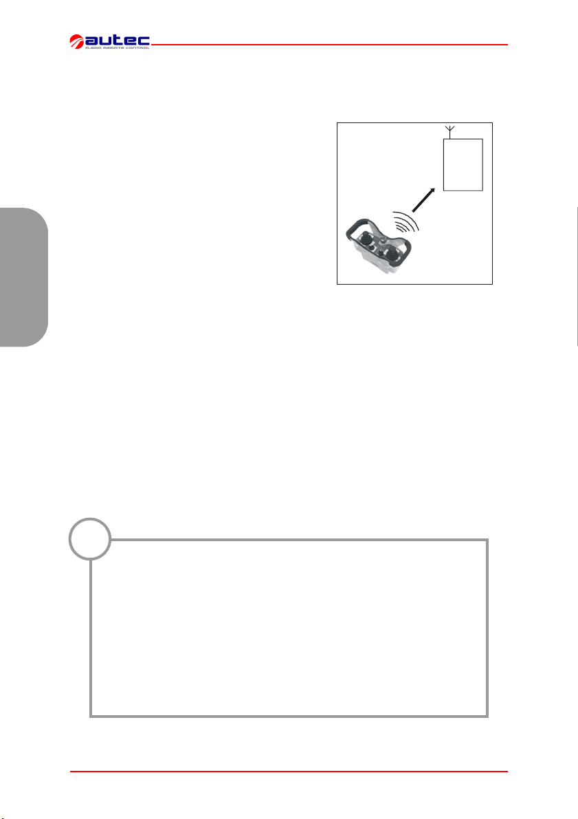
I radiocomandi industriali della serie Modular sono
utilizzati per comandare macchine da posizione remota. Ogni radiocomando industriale è costituito
da un’unità trasmittente portatile da cui l’operatore
può comandare a distanza la macchina e da
un’unità ricevente installata a bordo della macchina stessa.
Italiano
L’unità trasmittente, attraverso una trasmissione a
radiofrequenza, invia un messaggio codificato. In
questo messaggio è presente un valore detto indirizzo (address). Ogni unità ricevente può decodificare esclusivamente i messaggi provenienti dalla
unità trasmittente che possiede lo stesso indirizzo.
Ciò esclude che un’interferenza possa attivare una
qualunque funzione del sistema. Infatti, se la trasmissione a radiofrequenza risulta disturbata, errata o interrotta, l’unità ricevente arresta
autonomamente l’intero sistema.
Ogni radiocomando della serie Modular è conforme
alla Direttiva R&TTE 99/05/CE e ai suoi requisiti essenziali.
alle norme riportate nella dichiarazione di conformità CE allegata a questo manuale.
Ogni radiocomando è inoltre conforme
Unità
Trasmittente
Unità
Ricevente
!
Autec non potrà assumersi alcuna responsabilità se il radiocomando
è installato su applicazioni diverse da quelle consentite:
Macchine per sollevamento materiali (gru edili, carroponti industriali, macchine per la movimentazione materiale in genere,...).
Macchine per ambienti che necessitano di apparecchiature con caratteristiche di antideflagrazione.
Macchine per la movimentazione, il sollevamento e il trasporto di
persone.
Pagina 2 di 71 2 - Introduzione LIMJNMU0
APPLICAZIONI CONSENTITE
APPLICAZIONI NON CONSENTITE
Page 5

!
Si ricorda che in taluni stati si devono rispettare leggi che regolamentano:
- l’uso e/o il possesso di un radiocomando
- l’utilizzo delle frequenze di funzionamento non ancora armonizzato
nei paesi europei.
Nell’allegato “Limitazioni & Autorizzazioni” al presente manuale è
possibile trovare tutte le indicazioni da osservare.
Come richiesto dalla Direttiva Macchine e dalle relative norme armonizzate, è necessario effettuare per ogni macchina un’analisi dei rischi: pertanto, in caso di utilizzo di
un radiocomando, occorre valutare all’interno di questa analisi se la macchina può essere radiocomandata o meno.
La responsabilità di questa analisi è del costruttore della macchina stessa e/o di chi
decide l’installazione e l’uso del radiocomando.
Autec non potrà assumersi alcuna responsabilità se questa analisi dei rischi
non è stata effettuata in maniera corretta.
Per garantire il corretto utilizzo del radiocomando, devono essere sempre rispettate
tutte le prescrizioni vigenti sulla sicurezza del lavoro e sulla prevenzione degli infortuni
sul lavoro. Inoltre, si devono sempre osservare tutte le leggi nazionali relative all’uso
sia della macchina che del radiocomando vigenti nel singolo stato dove il sistema è
utilizzato.
Autec non potrà assumersi alcuna responsabilità se il radiocomando è utilizzato
in condizioni lavorative non a norma.
LIMITAZIONI & AUTORIZZAZIONI
Italiano
In caso di guasto o emergenza, si deve mettere fuori servizio il siste-
!
ma “macchina+radiocomando” fino alla completa eliminazione del
problema esistente.
Eventuali parti danneggiate possono essere sostituite SOLTANTO da personale autorizzato Autec, utilizzando ESCLUSIVAMENTE parti di ricambio originali Autec.
LIMJNMU0 2 - Introduzione Pagina 3 di 71
Page 6

La documentazione allegata ad ogni radiocomando è composta almeno da:
- manuale dell’unità trasmittente
- manuale dell’unità ricevente
- manuale del caricabatterie
- dichiarazione di conformità CE
- certificato di garanzia
Italiano
- scheda tecnica
- allegato “Limitazioni & Autorizzazioni”.
Verificare che siano presenti questi documenti allegati: in caso contrario farne richiesta ad Autec specificando il numero di matricola del radiocomando.
Le condizioni che regolano la garanzia del radiocomando sono riportate sul “Certificato di Garanzia” contenuto nel presente manuale.
Le parti elettroniche con 3 anni di garanzia sono: E16STXEU_, E16SRXEU_ e
E16SCHEU_.
La scheda tecnica rappresenta lo schema di cablaggio tra l’unità ricevente e la
macchina. Deve essere compilata e controllata dall’installatore il quale ha la responsabilità del corretto cablaggio. Effettuate queste necessarie verifiche, l’installatore deve firmare la scheda tecnica che deve rimanere allegata al manuale d’uso
(nel caso in cui la si utilizzi per pratiche amministrative tenerne sempre una copia).
ISTRUZIONI PER GESTIONE DOCUMENTI
CERTIFICATO DI GARANZIA
SCHEDA TECNICA
I dati di identificazione e di omologazione del radiocomando sono riportati su apposite targhette sia sull’unità trasmittente che sull’unità ricevente.
Tali targhette NON DEVONO essere né rimosse dalla loro posizione né alterate o rovinate per nessun motivo. La rimozione comporta l’immediata decadenza della garanzia.
Banda di frequenze ............................................................... 434.040 - 434.790 MHz
............................................................................... * oppure 433.050 - 434.790 MHz
............................................................................... * oppure 869.700 - 870.000 MHz
Canali radio utilizzabili.................................................... 16 (434.040 - 434.790 MHz)
....................................................................................... 32 (433.050 - 434.790 MHz)
....................................................................................... 12 (869.700 - 870.000 MHz)
Canalizzazione utilizzata.................................................................................. 25kHz
Distanza di Hamming .............................................................................................. ≥8
Probabilità di mancata rilevazione dell’errore........................................... <10 exp-11
Raggio d’azione tipico ....................................................................................... 100 m
Tempo di risposta dei comandi ................................................................... < 100 ms
Tempo di risposta comando di STOP ......................................................... < 100 ms
Tempo di emergenza passiva ................................................................. ** 0,5/1 sec.
* vedere allegato “Limitazioni & Autorizzazioni” per scegliere la banda di lavoro consentita e il paragrafo 8 "Pro-
grammazioni" per l’eventuale settaggio.
** vedere paragrafo “Programmazioni” del manuale dell’unità ricevente, impostazioni DIP n°1.
Pagina 4 di 71 2 - Introduzione LIMJNMU0
TARGHETTE IDENTIFICAZIONE
DATI TECNICI GENERALI
Page 7

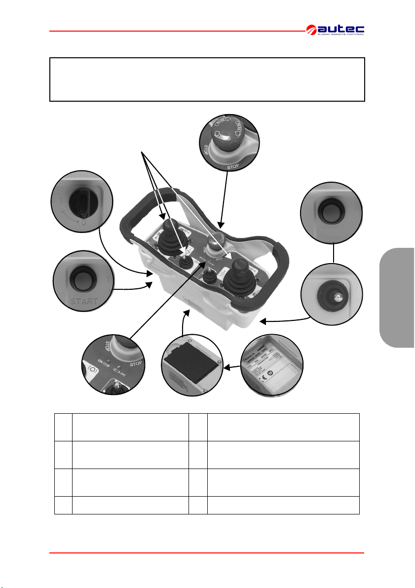
3 UNITÀ TRASMITTENTE MJ
Queste unità trasmittenti possono essere utilizzate con una delle seguenti unità riceventi:
- Type R102
- Type R202
.
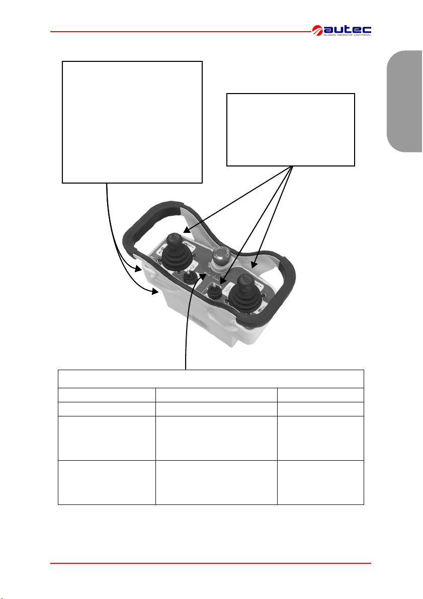
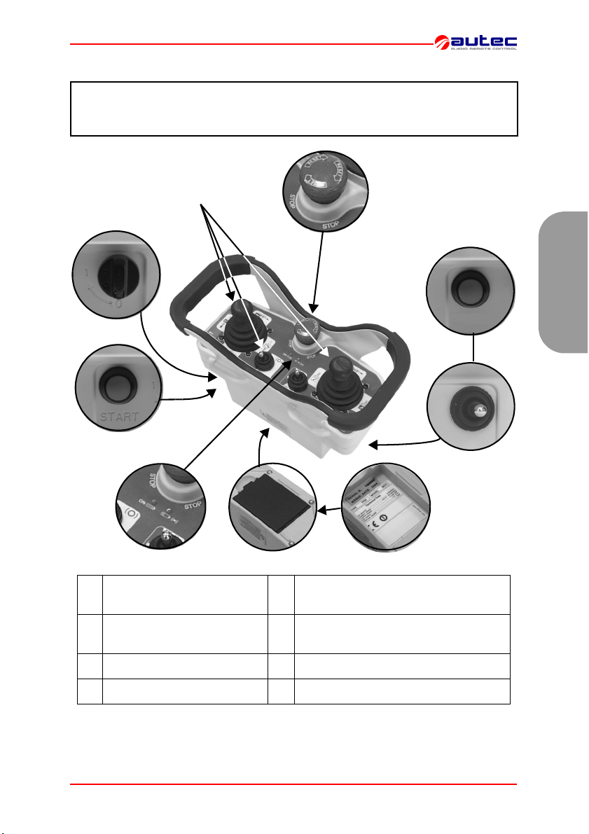
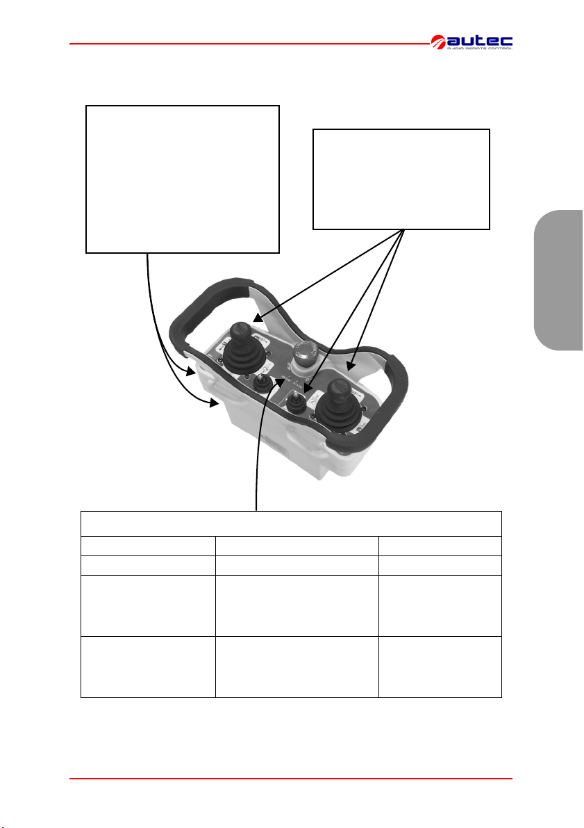
A
H
B
C
Italiano
D
A attuatori (joystick e selettori) E batteria (sul fondo)
B chiave di accensione F
C pulsante di START G pulsante e/o selettore (opzionale)
D led di segnalazione H pulsante di STOP
LIMJNMU0 3 - Unità trasmittente MJ Pagina 5 di 71
E
F
targhetta di identificazione e targhetta
dati tecnici (nel vano batteria)
G
Page 8

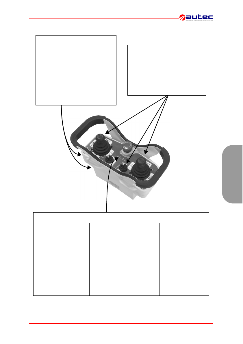
Le unità trasmittenti della serie Modular sono dotate di un doppio controllo che protegge il sistema “radiocomando+macchina”, in posizione neutra (di riposo), dai movimenti involontari dovuti ad eventuali guasti del radiocomando.
.
DATI TECNICI UNITÀ TRASMITTENTE MJ
Italiano
Alimentazione (pacco batteria MBM06MH)........................................ * NiMH 7,2 Vdc
Antenna........................................................................................................... interna
Custodia ............................................................................................... PA 6 (20% fg)
Grado di protezione............................................................................................. IP65
Temperatura di funzionamento ............................................................ -20°C - +55°C
Dimensioni................................................................................... (255x170x126 mm)
Peso .................................................................................................................. 1,3 kg
Potenza trasmettitore (frequenza 433 MHz) ........................................ < 10 mW ERP
Potenza trasmettitore (frequenza 870 MHz) .......................................... < 5 mW ERP
Autonomia con batteria carica (a 20°C) ........................................................... 14 ore
Tempo di preavviso batteria scarica............................................................... 3,5 min
* vedere dati tecnici della batteria nel manuale del caricabatterie.
Pagina 6 di 71 3 - Unità trasmittente MJ LIMJNMU0
Page 9
.
4 AVVERTENZE PER L’USO
!
L’OPERATORE
DOVRÀ SEMPRE
Italiano
SEGUIRE A VISTA tutti i movimenti della macchina e del carico rimanendo all’interno del raggio d’azione tipico.
POSIZIONARSI nelle condizioni migliori di visibilità diretta del sistema “macchina+radiocomando” e del carico.
Prima di iniziare a lavorare, VERIFICARE sempre il corretto funzionamento meccanico del pulsante di STOP: se non funziona, non utilizzare il radiocomando.
SPEGNERE l’unità trasmittente quando si sospende il lavoro, evitando di lasciare il carico sospeso (anche durante la sostituzione della
batteria scarica).
NON LASCIARE MAI l’unità trasmittente incustodita con la chiave
d’accensione inserita.
NON ACCENDERE O AZIONARE MAI l’unità trasmittente se non per
iniziare a lavorare: l’uso improprio potrebbe causare situazioni di pericolo.
NON ACCENDERE O AZIONARE MAI l’unità trasmittente in posti
chiusi fuori visibilità o fuori dal raggio tipico d’azione.
INTERVENIRE immediatamente azionando il pulsante di STOP quando si verifica una situazione di pericolo.
PRESTARE ATTENZIONE a tutta l’area di lavoro ed intervenire in
caso di pericolo azionando manualmente il pulsante di STOP.
FARE ATTENZIONE che sull’unità trasmittente non si depositino materiali (come cemento, sabbia, calce,...) che possano comprometterne l’utilizzo e la sicurezza.
In presenza di malfunzionamento, parti danneggiate e guasti, METTERE fuori servizio il radiocomando fino alla completa eliminazione
del problema.
LIMJNMU0 4 - Avvertenze per l’uso Pagina 7 di 71
Page 10

!
Italiano
L’unità trasmittente non necessita di particolari manutenzioni, tuttavia per lavorare con
un’unità sempre efficace e sicura è necessario:
PRIMA DELL’USO:
- verificare che l’unità sia integra,
- controllare che le guarnizioni, i soffietti ed i cappucci degli attuatori (joystick, selettori
e pulsanti) siano integri, morbidi ed elastici e che i simboli del pannello siano ben visibili,
DOPO L’USO:
- riporla sempre in ambienti puliti ed asciutti,
- accertarsi che la sede d’alloggiamento e i contatti della batteria siano puliti,
- rimuovere la polvere o accumuli di altro materiale dall’unità trasmittente con un panno
inumidito con acqua (per pulire non usare mai solventi, prodotti infiammabili o corrosivi, e non utilizzare idropulitrici ad alta pressione o apparecchi a vapore).
5 AVVERTENZE PER LA MANUTENZIONE
DURANTE TUTTE LE OPERAZIONI DI MANUTENZIONE, ACCERTARSI CHE VENGA TOLTA LA
BATTERIA DALL’UNITÀ TRASMITTENTE.
Eventuali guasti possono esclusivamente essere
riparati da personale autorizzato, utilizzando soltanto pezzi di ricambio originali Autec.
SERVIZIO ASSISTENZA
In tutti i casi di manutenzione straordinaria (riparazione del radiocomando e sostituzione di particolari danneggiati o guasti), interpellare esclusivamente l’Assistenza. Per
rendere possibile un intervento più veloce ed efficace, devono essere comunicati i dati
per una corretta e completa identificazione del radiocomando:
- numero di matricola
- data di acquisto (riportata sul certificato di garanzia)
- indirizzo e numero di telefono del luogo in cui è utilizzato
- anomalia riscontrata
- nome del responsabile da contattare
- ditta fornitrice.
Prima di far intervenire i tecnici dell’Assistenza, è opportuno verificare di aver
eseguito correttamente tutte le istruzioni riportate.
Per la rottamazione, affidare il radiocomando al servizio recupero differenziato dei rottami esistenti nel territorio.
Pagina 8 di 71 5 - Avvertenze per la manutenzione LIMJNMU0
ROTTAMAZIONE
Page 11
6 FUNZIONAMENTO UNITÀ TRASMITTENTE MJ
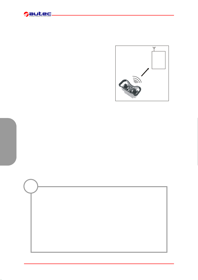
ACCENSIONE
ED AVVIAMENTO
Per accendere l’unità trasmittente,
inserire la chiave d’accensione e
ruotarla nella posizione “I”.
Per avviare le funzioni del radiocomando, premere il pulsante di
START per 1-2 secondi.
Dopo l’avviamento si accende sempre il led di segnalazione verde.
ATTIVAZIONE COMANDI
Azionare gli attuatori a joystick
e/o a selettore relativi a un qualunque comando di movimento
o di selezione che si intende effettuare.
Italiano
SEGNALAZIONI
TIPO SIGNIFICATO INTERVENTO
lampeggio led verde FUNZIONAMENTO NORMALE ///
lampeggio led rosso,
accompagnato dal suono
intermittente del buzzer
luce continua led rosso
all’avviamento, accompagnato dal suono continuo
del buzzer
LIMJNMU0 6 - Funzionamento unità trasmittente MJ Pagina 9 di 71
BATTERIA SCARICA l’unità tra-
smittente si spegne dopo 3,5
minuti dall’inizio del lampeggio
del led
UNO O PIÙ ATTUATORI (di
movimento) e/o IL PULSANTE
DI STOP INSERITI
spegnere l’unità tra-
smittente e sostituire
la batteria
disinserire tutti gli
attuatori e il pulsante
di STOP
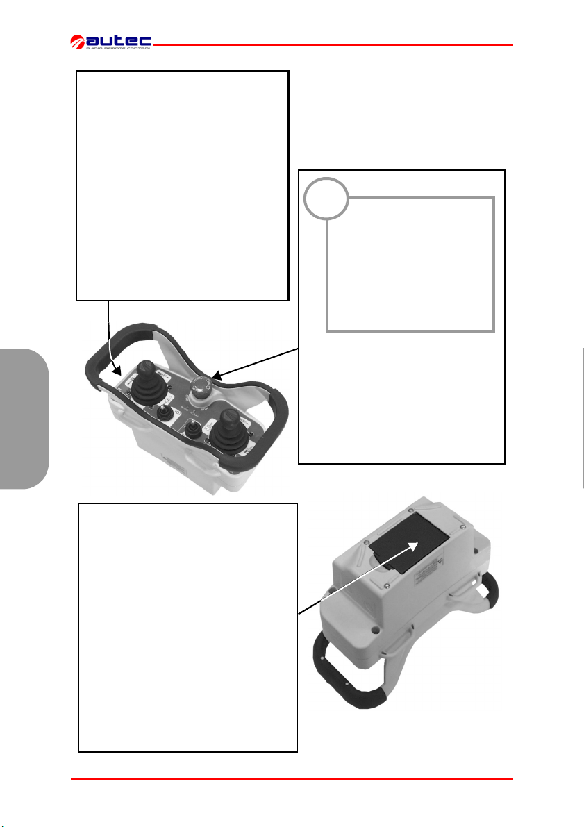
Page 12

L’unità trasmittente deve essere
spenta ogni volta che si sospende il
lavoro girando la chiave d’accensione in posizione “O” ed estraendola
(riporla sempre in un luogo sicuro).
Italiano
Lo spegnimento dell’unità trasmittente
può anche avvenire quando la batteria
non è sufficientemente carica e/o quando il radiocomando non viene utilizzato
per circa 3 minuti e mezzo (vedere paragrafo 8 "Programmazioni" impostazioni DIP n°1.).
SPEGNIMENTO
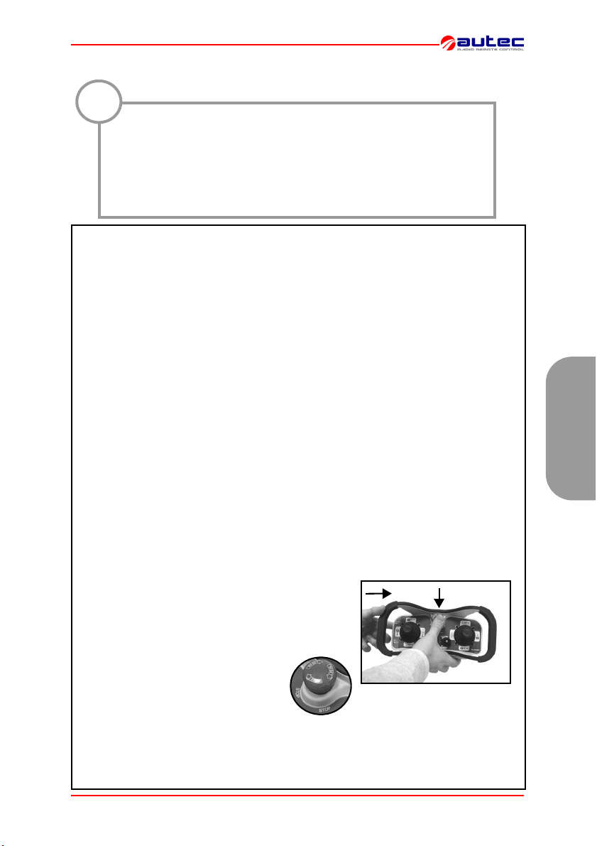
!
Il pulsante di STOP va attivato quando c’è la necessità di arrestare
immediatamente la macchina per il verificarsi di
una qualunque situazione di pericolo.
Per arrestare immediatamente la
macchina, premere il pulsante di
STOP.
Per riprendere a lavorare, dopo aver
verificato che le condizioni lavorative
siano sicure, ruotare nel verso indicato
il pulsante di STOP per disinserirlo e
ripetere la procedura di avviamento.
STOP
BATTERIA
Per caricare una batteria scarica, seguire
la seguente procedura:
1. Inserirla nell’apposito caricabatterie posto in un luogo alla temperatura compresa
tra +5°C e +45°C: inizia così la carica della
batteria segnalata dalla spia “CHARGE”.
2. Dopo un massimo di 3 ore, la spia
“CHARGE” si spegne: la batteria è carica.
Estrarla dal caricabatteria (se non estratta,
la carica continua con una corrente di
mantenimento).
Pagina 10 di 71 6 - Funzionamento unità trasmittente MJ LIMJNMU0
Page 13

7 FREQUENZE
!
Negli stati europei, la banda di frequenze 869.700 - 870.000 MHz è armonizzata, mentre la banda 433.050 - 434.790 MHz non è armonizzata. Verificare eventuali limitazioni nel paese di utilizzo.
Ad esempio alcuni stati europei permettono l'utilizzo di questi apparati radio soltanto nella banda di frequenze 434.050-434.790 MHz.
Nei radiocomandi AUTEC la frequenza radio di lavoro appartiene all’insieme delle frequenze ammesse dalle normative europee in vigore al momento dell’immissione nel mercato.
Un radiocomando può essere programmato in modalità di scansione AUTOMATICA
(programmazione standard del costruttore) o in modalità di selezione MANUALE.
MODALITÀ DI SELEZIONE MANUALE
Operare in modalità di selezione MANUALE consente di lavorare ad una specifica frequenza che deve essere impostata manualmente programmando i dip switch presenti
nei moduli radio (vedere paragrafo 8 "Programmazioni").
Per impostare o modificare questa modalità di funzionamento contattare personale autorizzato Autec.
MODALITÀ DI SCANSIONE AUTOMATICA
Operare in modalità di scansione AUTOMATICA consente di funzionare ad una specifica frequenza che, in caso di interferenza o di conflitto con altri impianti radio, può
essere cambiata attraverso la procedura “Cambio della frequenza di lavoro”.
Tale modalità consente di non intervenire all’interno né dell’unità trasmittente né
dell’unità ricevente.
Italiano
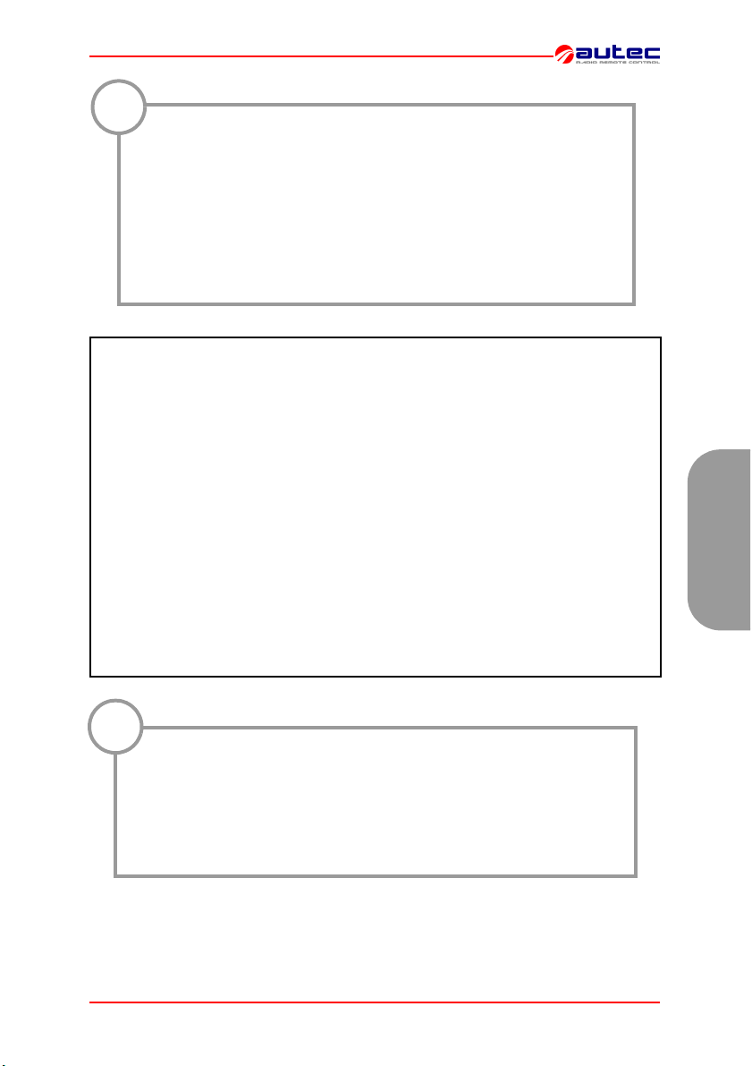
Cambio della frequenza di lavoro
1 Con unità trasmittente avviata (led verde lampeg-
giante):
- premere il pulsante di START senza rilasciarlo (a)
- premere successivamente il pulsante di STOP (b)
- rilasciare infine il pulsante di START.
2 Ruotare nel verso indicato il pulsante
di STOP per disinserirlo e ripetere la
procedura di avviamento.
N.B.: Durante il cambiamento della frequenza di lavoro, l’unità ricevente perde il collegamento radioelettrico con l’unità trasmittente.
Dopo l’avviamento, possono essere richiesti alcuni secondi per il ripristino del
collegamento: mantenere quindi premuto il pulsante di START per circa 8-10 secondi.
LIMJNMU0 7 - Frequenze Pagina 11 di 71
a
b
Page 14

8 PROGRAMMAZIONI
La programmazione dei dip switches deve essere eseguita con unità
!
trasmittente senza batteria e può essere effettuata soltanto da personale autorizzato.
Italiano
Il gruppo di otto dip switches presente nel modulo serve a programmare alcune funzionalità e
impostare la frequenza di lavoro.
Viceversa, non si deve mai modificare la programmazione impostata nell’altro gruppo
presente di quattro dip switches.
DIP MODULO STATO FUNZIONE
1 E16STXEU_
2 E16STXEU_
3
8 E16STXEU_
DIP SWITCHES DEL MODULO RADIO TRASMITTENTE E16STXEU_
Gruppo di 8
dip switches
Gruppo di 4
dip switches
Gruppo di 8 dip switches
ON L’unità trasmittente non si spegne automaticamente
L’unità trasmittente accesa senza comandi di movimento
E16STXEU1
E16STXEU2
OFF
ON
Attivazione dell’avviso di batteria scarica tramite il clac-
OFF
Modalità di scansione automatica delle frequenze nella
ON
Modalità di scansione automatica delle frequenze nella
OFF
ON NON UTILIZZARE
Modalità di scansione automatica delle frequenze nella
OFF
ON
(DIP 3 - DIP 7 vedi “FREQUENCY TABLE” a pagina 71)
Modalità di selezione e scansione automatica delle fre-
OFF
inseriti, si spegne dopo circa 3,5 min.
Disattivazione dell’avviso di batteria scarica tramite il
clacson della macchina
son della macchina
banda 433.050 - 434.040 MHz
banda 434.050 - 434.790 MHz
banda 869.700 - 870.000 MHz
Modalità di selezione manuale delle frequenze
quenze (DIP 3 - DIP 7 OFF)
!
Questi otto dip switches devono essere programmati come il gruppo di 8 dip switches (eccetto il DIP 1) del modulo radio dell’unità ricevente (vedi manuale).
Pagina 12 di 71 8 - Programmazioni LIMJNMU0
Page 15

9 DIAGNOSTICA UNITÀ TRASMITTENTE MJ
Nel caso in cui il sistema “macchina + radiocomando” non si avvii, è opportuno controllare
se il problema interessa il radiocomando o la macchina. Perciò, prima di qualunque verifica,
controllare con il posto comando a cavo il funzionamento della macchina:
- se non si avvia, il problema interessa la macchina stessa
- se si avvia, il problema riguarda il radiocomando. In tal caso, procedere come nella seguente procedura:
Azionando lo
START, il led rosso
è acceso con luce
fissa, e il buzzer
suona?
NO
SI
Il pulsante di
STOP o uno degli
attuatori di
movimento sono
inseriti:
disinserirlo/i.
Il led è acceso con
luce fissa?
NO
SI
Italiano
Il led rosso
lampeggia e il
buzzer suona?
NO
Il led verde
lampeggia?
NO
Se il problema per-
siste,
CHIAMARE
ASSISTENZA
La batteria è scarica:
sostituirla con una
SI
sicuramente carica.
Continua a lampeg-
giare il led e a suo-
nare il buzzer?
SI
Effettuare le
operazioni di
diagnostica relative
all’unità ricevente
NO
Pulire i contatti nella
sede d’alloggiamen-
SI
to della batteria
Continua a lampeg-
giare il led e a suo-
nare il buzzer?
SI
NO
LIMJNMU0 9 - Diagnostica unità trasmittente MJ Pagina 13 di 71
Page 16

Italiano
Pagina 14 di 71 LIMJNMU0
Page 17
1 INDEX AND CONVENTIONS
INDEX
1 Index and conventions................................................................................................... 15
2 Introduction.................................................................................................................... 16
3 MJ transmitting unit ....................................................................................................... 19
4 Warnings for use ........................................................................................................... 21
5 Warnings for maintenance............................................................................................. 22
6 MJ transceiving unit operation....................................................................................... 23
7 Frequencies...................................................................................................................25
8 Programming................................................................................................................. 26
9 MJ transmitting unit diagnostics .................................................................................... 27
CONVENTIONS
In this manual, all important information is indicated using the following symbols and conventions:
!
abcd....
abcd.... abcd....
THIS MANUAL REFERS EXCLUSIVELY TO THE TRANSMITTING UNIT: THE INSTALLATION WARNINGS ARE GIVEN IN THE RECEIVING UNIT MANUAL.
BEFORE INSTALLING, STARTING AND USING THE RADIO REMOTE CONTROL,
THIS MANUAL MUST BE READ AND UNDERSTOOD CAREFULLY BY ALL PEOPLE
WHO INSTALL, USE AND CARRY OUT MAINTENANCE ON THE RADIO REMOTE
CONTROL.
: WARNINGS
: TECHNICAL
DATA
abcd....
: INSTRUC-
TIONS
: IMPORTANT
TEXTS
English
LIMJNMU0 1 - Index and conventions Page 15 of 71
Page 18
2 INTRODUCTION
Industrial radio remote controls of the Modular series are used to command machines from a distance. Each industrial radio remote control is made
up of a portable transmitting unit, from which the
user can remotely control the machine, and a receiving unit installed on board the machine itself.
The transmitting unit uses radio frequencies to
transmit a coded message which contains a value
called address. Each receiving unit can only decode the messages coming from a transmitting unit
with the same address.
This excludes the possibility of an interference activating any system function. If the radio frequency
transmission is disturbed, incorrect or interrupted,
the receiving unit autonomously stops the whole
system.
English
Each Modular series radio remote control is in conformity
with the R&TTE 99/05/CE Directive and all its essential requisites.
Each radio remote control is also in conformity with the norms
given in the EC conformity declaration supplied with this manual.
Tra nsmi tti ng
unit
Receiving
unit
!
Autec cannot be held responsible if the radio remote control is installed on applications that are different from those permitted:
Material lifting machines (construction cranes, industrial bridge
cranes, machines for moving material in general, . . . ).
Machines installed in areas where equipment with explosion-proof
characteristics are being used.
Machines for moving, raising and transporting people.
Page 16 of 71 2 - Introduction LIMJNMU0
PERMITTED USES
FORBIDDEN USES
Page 19
!
It should be remembered that in some countries must be respected
rules which control:
- the use and/or possession of a radio remote control;
- the use of operational frequencies which have not yet been harmonised in Europe.
All the indications that must be observed can be found in the “Limitations & Authorizations” document, which is included in the product’s documentation.
As required by the Machines Directive and relative harmonised standards, all machines must undergo a risk analysis; therefore it is necessary to evaluate, within the
limits of this analysis, if the machine can be radio remote controlled.
The machine producer and/or the person who decides upon radio remote control use
and installation is responsible for this analysis.
Autec cannot be held responsible if the risk analysis is not carried out correctly.
To guarantee correct radio remote control operation, all current regulations regarding
safety at work and accident prevention should be respected. All current user country
national laws regarding the use of both the machine and the radio remote control
MUST ALWAYS be respected.
Autec cannot be held responsible if the radio remote control is used in unlawful
working conditions.
LIMITATIONS & AUTHORIZATIONS
English
!
In any cases of emergencies, faults or damaged parts, ALWAYS stop
the “machine + radio remote control” system until the problem has
been solved.
Any damaged parts can ONLY be replaced by authorised Autec personnel, and only using original Autec spare parts.
LIMJNMU0 2 - Introduction Page 17 of 71
Page 20

The following minimum documentation is supplied with each radio remote control:
- transmitting unit manual
- receiving unit manual
- battery charger manual
- a CE conformity declaration
- a guarantee certificate
- the radio remote control technical data sheet
- the enclosed “Limitations & Authorisations”.
Make sure that the following documents have been supplied: if they are not, re-
quest them from Autec. Please specify the radio remote control serial number.
The conditions of the radio remote control guarantee are given in the “Certificate of
Guarantee” contained in this manual.
The electronic components which have a 3 year guarantee are: E16STXEU_,
E16SRXEU_ and E16SCHEU_.
English
The technical data sheet shows the wiring system between the receiving unit and
the machine. It should be compiled and checked by the installer, who has the re-
sponsibility of correct wiring. Once all necessary checks have taken place the in-
staller must sign the technical data sheet, which must be kept with the user's
manual (always keep a copy of this data sheet in case it is needed for administra-
tive purposes).
The radio remote control identification and approval data is given on plates that are
on both the transmitting unit and the receiving unit.
The plates MUST NOT be removed from where they are placed or damaged oth-
erwise the warranty will be forfeited.
INSTRUCTIONS FOR DOCUMENT MANAGEMENT
CERTIFICATE OF GUARANTEE
TECHNICAL DATA SHEET
IDENTIFICATION PLATES
MODULAR SERIES TECHNICAL DATA
Frequency band .................................................................... 434.040 - 434.790 MHz
....................................................................................... * or 433.050 - 434.790 MHz
....................................................................................... * or 869.700 - 870.000 MHz
Programmable radio channel ......................................... 16 (434.040 - 434.790 MHz)
....................................................................................... 32 (433.050 - 434.790 MHz)
....................................................................................... 12 (869.700 - 870.000 MHz)
Channel spacing............................................................................................... 25kHz
Hamming distance................................................................................................... ≥8
Probability of non-recognition of error ...................................................... <10 exp-11
Typical working range ....................................................................................... 100 m
Time of reply to commands ......................................................................... < 100 ms
Time of reply to STOP................................................................................. < 100 ms
Passive emergency time ......................................................................... ** 0,5/1 sec.
* refer to the “Limitations & Authorisations” insert to select the permitted working band and paragraph 8 "Programming" if setting is necessary.
** refer to paragraph “Programming” in the receiving unit manual, DIP nr. 1 settings.
Page 18 of 71 2 - Introduction LIMJNMU0
Page 21
3 MJ TRANSMITTING UNIT
These transmitting units can be used with one of the following receiving units:
- Type R102
- Type R202.
A
H
B
C
D
actuators (joysticks and
A
B starting keyswitch F
C START pushbutton G pushbutton and/or selector (optional)
D signalling LED H STOP pushbutton
selectors)
E
F
E battery (at the bottom)
technical data plate and identification
plate (in the battery housing)
G
English
LIMJNMU0 3 - MJ transmitting unit Page 19 of 71
Page 22
The transmitting units of Modular series are equipped with a redundant control that
protects the “radio remote control + machine” system, when it is in neutral (rest position), from involuntary movements caused by possible radio remote control faults.
.
MJ TRANSMITTING UNIT TECHNICAL DATA
Power supply (rechargeable battery MBM06MH) .............................. * NiMH 7,2 Vdc
Antenna.......................................................................................................... internal
Housing ................................................................................................ PA 6 (20% fg)
Minimum protection grade................................................................................... IP65
Operating temperature range ............................................................... -20°C - +55°C
Dimensions.................................................................................. (255x170x126 mm)
Weight ............................................................................................................... 1,3 kg
Transmitting power (frequency 433 MHz) ............................................ < 10 mW ERP
Transmitting power (frequency 870 MHz) .............................................. < 5 mW ERP
Battery operation time (at 20°C in countinuous use) ................................... 14 hours
English
Warning of low battery charge........................................................................ 3,5 min
* refer to battery technical data in the battery charger manual.
Page 20 of 71 3 - MJ transmitting unit LIMJNMU0
Page 23
4 WARNINGS FOR USE
.
!
THE OPERATOR
MUST ALWAYS
VISUALLY FOLLOW all movements of the machine and its load remaining inside radio remote control typical working range.
BE POSITIONED in a way that permits him to see the
“machine + radio remote control” system, and above all the load, in
the best possible way.
Before using the radio remote control ALWAYS MAKE SURE that the
STOP push-button can be pressed and released: if it does not work,
do not use the radio remote control.
SWITCH OFF the transmitting unit when work is interrupted. Avoid
leaving the load suspended in the air (even when changing the battery).
NEVER LEAVE the transmitting unit unguarded when the starting
keyswitch is inserted.
ONLY SWITCH ON OR USE the transmitting unit when starting work:
improper use could be hazardous.
NEVER SWITCH ON OR USE the transmitting unit in closed spaces,
with the machine not in sight, or outside the typical working range.
PRESS immediately the STOP button in case of hazard.
PAY ATTENTION to the entire work area. Press the STOP button in
case of hazard.
PAY ATTENTION not to let elements such as cement, sand, lime, etc.
deposit on the transmitting unit because they can compromise
transmitting unit use and safety.
In case of malfunctions and/or damaged and/or faulty parts, PUT the
radio remote control out of use until the problem has been completely eliminated.
English
LIMJNMU0 4 - Warnings for use Page 21 of 71
Page 24

5 WARNINGS FOR MAINTENANCE
!
ENSURE THAT THE BATTERY HAS BEEN REMOVED FROM THE TRANSMITTING UNIT BEFORE CARRYING OUT ANY MAINTENANCE
WORK.
Any faults should be repaired by authorised Autec personnel using original Autec spare parts
only.
No particular maintenance needs to be carried out on the transmitting unit, but the following should be done in order to always keep it reliable and safe:
English
BEFORE USING:
- make sure that the unit is integral,
- make sure that the gaskets, bellows and the actuator hoods (joystick, selectors and
pushbuttons) are whole, soft and elastic, and that the symbols on the panel can be
seen clearly.
AFTER USE:
- always store the unit in a clean dry place,
- make sure that the battery seat is and contacts are clean,
- remove dust or any other material that has deposited on the transmitting unit with a
cloth that has been dampened with water (never use solvents or flammable/corrosive
materials to clean, and do not use high pressure water cleaners or stream cleaners).
When it is necessary to carry out special maintenance (radio remote control repair and
replacement of damaged or faulty parts), do not contact anyone other than our Assistance Service. In order to make the intervention faster and more reliable, please help
us identify the radio remote control correctly and completely by giving:
- the serial number
- the purchase date (given on the guarantee)
- description of the problem found
- the address and telephone number of the place where the radio remote control is being used
- the name of the person to be contacted
- the name of the company that supplied the radio remote control.
Before calling the Assistance technicians, it is advisable to make sure that the
given instructions have been followed correctly.
SERVICE
When scrapping, entrust the radio remote control to the separate scrap collecting services in the user country.
Page 22 of 71 5 - Warnings for maintenance LIMJNMU0
SCRAPPING
Page 25
6 MJ TRANSMITTING UNIT OPERATION
POWER AND STARTING
To switch on the transmitting unit, insert the starting key and turn it to "I".
To start the radio remote control
functions, press the “START” button
for 1-2 seconds.
After starting, the green signalling
LED always lights up.
COMMAND ACTIVATION
Activate the joystick and/or selector actuators relevant to
whatever movement or selection command is to be carried
out.
English
SIGNALS
TYPE MEANING ACTION
blinking green LED OPERATION NORMAL ///
blinking red LED, accom-
panied by intermittent
sounds from the buzzer
steady red LED at start-
ing, accompanied by the
continuous sound from
the buzzer
LIMJNMU0 6 - MJ transmitting unit operation Page 23 of 71
LOW BATTERY.
The transmitting unit switches
off 3 and half minutes after the
LED starts flashing
ONE OR MORE (movement)
ACTUATORS and/or STOP
PUSHBUTTON INSERTED
Switch off the transmit-
ting unit and replace
the battery
Release actuator(s)
and the STOP push-
button
Page 26

The transmitting unit should be
switched off each time work is
stopped by turning the starting key
to "O" and extracting it (always put
the key in a safe place).
The unit may also switch off if the battery is not sufficiently charged and/or
when the radio remote control is not
used for more than 3 and half minutes
(refer to paragraph 8 "Programming"
DIP nr. 1 settings.).
English
SWITCHING OFF
!
The STOP button should
be used when it is necessary to stop the machine immediately in
order to check any danger condition.
To stop the machine immediately,
press the STOP button.
To start working again, after having
made sure that the working conditions
are safe, turn the STOP button in the
direction indicated to deactivate it and
repeat the starting procedure.
STOP
BATTERY
To recharge a flat battery, proceed as follows:
1. Insert the battery into its proper battery
charger, which should be positioned in an
area having a temperature of between
+5°C and +45°C. The battery now starts
charging, a state signalled by the lighting
up of the “CHARGE” pilot light.
2. After a maximum of 3 hours the
"CHARGE" indicator switches off: the battery is fully charged. Remove the battery
from the charger (if the battery is not removed, charging continues in maintenance mode).
Page 24 of 71 6 - MJ transmitting unit operation LIMJNMU0
Page 27

7 FREQUENCIES
!
The use of 869.700 - 870.000 MHz frequencies band has been harmonised in Europe. The use of 433.050 - 434.790 MHz frequencies band
has not been harmonised in Europe yet: check for possible user’s
country limitations.
For example, some European countries only permit the use of this radio equipment in the 434.040 - 434.790 MHz band.
The radio frequency of AUTEC radio remote controls is included in the group of
frequencies permitted by those European regulations that are current at the moment of radio remote control entry onto the market.
Each radio remote control is programmed by the producer in the AUTOMATIC scan
mode (producer's standard programming) or MANUAL selection mode.
MANUAL SELECTION MODE
When operating in the MANUAL selection mode it is possible to work at a specific frequency that must be set manually by programming the dip switches in the radio modules (refer to paragraph 8 "Programming").
To set or modify this operation mode contact personnel that have been authorised by Autec.
English
When operating in the AUTOMATIC scan mode it is possible to operate at a specific
frequency, which can be changed in case of interference or conflict with other radio
equipment using the “Changing the operating frequency” procedure.
This mode avoids internal interventions on the transmitting unit and the receiving unit.
1 With the transmitting unit started (blinking green
LED):
- press the START pushbutton and keep it pressed
(a),
- press the STOP pushbutton (b),
- release the START pushbutton
2 Unlock the STOP pushbutton by
turning it as shown in the photo and repeat the starting procedure.
N.B.: During the work frequency changing process, the receiving unit loses radioelectric connection with the transmitting unit.
After starting, some seconds may be necessary to reset connection, therefore
keep the START button pressed for about 8-10 seconds.
LIMJNMU0 7 - Frequencies Page 25 of 71
AUTOMATIC SCAN MODE
Working frequency change process
a
b
Page 28

!
The group of eight dip switches
found in the module is necessary
for programming some operations and setting the operating
frequency.
The programming set in the other group of four dip switches
must never be modified.
English
DIP MODULE POS. DESCRIPTION
1 E16STXEU_
2 E16STXEU_
3
8 E16STXEU_
8 PROGRAMMING
The dip switches must be programmed with the battery removed
from the transmitting unit and can be done only by authorised personnel.
DIP SWITCHES ON E16STXEU_ RADIO TRANSMITTING UNIT
Group of 8
dip switches
Group of 4 dip
switches
Group of 8 dip switches
ON The transmitting unit never switches off automatically
The transmitting unit switched on without movement
OFF
E16STXEU1
E16STXEU2
commands entered switches off after approx. 3 and half
ON
OFF Activation of low battery warning from horn on machine
ON
OFF
ON DON’T USE
OFF
ON
OFF
Deactivated of low battery warning from horn on
Automatic scan mode of the frequencies in the
Automatic scan mode of the frequencies in the
Automatic scan mode of the frequencies in the
Manual selection of frequencies
(DIP 3 - DIP 7 see “FREQUENCY TABLE” on page 71)
Automatic selection and scanning of frequencies
minutes
machine.
433.050 - 434.040 MHz
434.050 - 434.790 MHz
869.700 - 870.000 MHz
(DIP 3 - DIP 7 OFF)
!
These eight dip switches must be programmed in the same manner
as the group of 8 dip switches (excluding DIP 1) present in the radio
module of the receiving unit (see manual).
Page 26 of 71 8 - Programming LIMJNMU0
Page 29

9 MJ TRANSMITTING UNIT DIAGNOSTICS
If the “machine+radio remote control” system does not start, check if the problem is caused
by the radio remote control or the machine. Before carrying out any verifications, check the
functioning of the machine with the cable control panel:
- if it does not switch on, the problem lies with the machine itself
- if it does switch on, the problem lies with the radio remote control. In this case, proceed
as follows:
When START is
activated, is the red
LED lit steadily and
does the buzzer
sound?
NO
Does the red LED
blink and does the
buzzer sound?
NO
Does the green
LED blink?
NO
If the problem
persists
CALL
TECHNICAL
ASSISTANCE
Is the STOP button
YES
YES
YES
or one of the
actuator inserted?
Release it/them
The battery is dis-
charged: replace it
with one that is
charged. Does it con-
tinue to blink quickly
and the buzzer sound-
diagnostics checks
on the receiving
movement
ing?
NO
Carry out
unit.
Is the led on with a
steady light?
Clean the contacts
in the battery seat.
YES
Does it continue to
blink quickly and the
buzzer sounding?
YES
NO
English
YES
NO
LIMJNMU0 9 - MJ transmitting unit diagnostics Page 27 of 71
Page 30

English
Page 28 of 71 LIMJNMU0
Page 31

1 INDEX UND KONVENTIONEN
INDEX
1 Index und Konventionen................................................................................................ 29
2 Einleitung....................................................................................................................... 30
3 Sendeeinheit MJ............................................................................................................ 33
4 Gebrauchsanweisungen................................................................................................ 35
5 Wartungsanweisungen.................................................................................................. 36
6 Arbeitsweise Sendeeinheit MJ ...................................................................................... 37
7 Frequenzen ................................................................................................................... 39
8 Programmierung............................................................................................................ 40
9 Sendeeinheit MJ-Fehlersuche....................................................................................... 41
KONVENTIONEN
In diesem Handbuch werden alle wichtigen Informationen mit den folgenden Symbolen und
Konventionen hervorgehoben:
!
abcd....
abcd.... abcd....
DAS VORLIEGENDE HANDBUCH BEZIEHT SICH AUSSCHLIEßLICH NUR AUF DIE
SENDEEINHEIT: DIE WARNUNGEN, DIE DIE INSTALLATION BETREFFEN, SIND IN
DER GEBRAUCHSANLEITUNG DER EMPFANGSEINHEIT ZU FINDEN.
BEVOR MAN DIE FUNKFERNSTEUERUNG INSTALLIERT, IN BETRIEB SETZT ODER
BENUTZT, MUß DAS VORLIEGENDE HANDBUCH VON ALLEN FÜR DIE INSTALLATION, BENUTZUNG UND WARTUNG VERANTWORTLICHEN PERSONEN AUFMERKSAM GELESEN UND VERSTANDEN WORDEN SEIN.
LIMJNMU0 1 - Index und Konventionen Seite 29 von 71
: ANWEISUN-
GEN
: TECHNISCHE
DATE
abcd....
: ANLEITUN-
GEN
: WICHTIGE
TEXTE
Deutsch
Page 32
Die industriellen Funkfernsteuerungen der Serie
Modular werden benutzt, um Maschinen aus entfernter Position zu steuern. Jede industrielle Funkfernsteuerung besteht aus einer tragbaren
Sendeeinheit, von der der Bediener die Maschine
aus Entfernung steuern kann, sowie aus einer
Empfangseinheit, die am Rand der Maschine angebracht ist.
Die Sendeeinheit sendet mittels Funkübertragung
eine kodierte Nachricht. In dieser Nachricht ist ein
Wert vorhanden, der Adresse genannt wird. Jede
Empfangseinheit kann ausschließlich nur die
Nachrichten dekodieren, die von der Sendeeinheit
stammen, die dieselbe Adresse hat. Dadurch wird
verhindert, dass eine Interferenz eine jegliche
Funktion des Systems aktivieren kann. Tatsächlich
hält die Empfangseinheit das gesamte System
selbst an, falls sich die Funkübertragung als gestört, fehlerhaft oder unterbrochen herausstellen
sollte.
Jede Funkfernsteuerung der Serie Modular stimmt mit
der Vorschrift R&TTE 99/05/CE und ihren wesentlichen Erfordernissen überein.
Deutsch
Außerdem stimmt jede Funkfernsteuerung mit allen Vorschriften überein,
die in der beiliegenden Konformitätserklärung "CE" aufgeführt sind.
2 EINLEITUNG
Sendeeinheit
Empfangs-
einheit
!
Autec kann keine Verantwortung übernehmen, wenn die Funkfernsteuerung für Anwendungszwecke benutzt wird, die von den vorgesehenen abweichen:
GESTATTETE ANWENDUNGEN
Maschinen für die Hebung von Materialien (Baukrane, industrielle
Laufkrane, Maschinen für den Transport von Materialien im allgemeinen, . . . ).
Maschinen, die in Gegenden installiert sind, die Geräte mit explosionssicheren Eigenschaften voraussetzen und Maschinen für die Bewegung, die Hebung und den Transport von Personen.
Seite 30 von 71 2 - Einleitung LIMJNMU0
NICHT GESTATTETE ANWENDUNGEN
Page 33
!
Wir erinnern daran, dass man in einigen Ländern Gesetze befolgen
muß, die folgendes regeln:
- den Gebrauch und/oder den Besitz einer Funksteuerung
- den Gebrauch von Betriebsfrequenzen, der in den europäischen
Staaten noch nicht abgestimmt wurde.
In der diesem Handbuch beigefügten Anlage "Beschränkungen &
Genehmigungen" findet man alle zu beachtenden Angaben.
Wie es von der Maschinenvorschrift und ihren entsprechenden Weisungen vorgesehen wird, ist es notwendig, für jede Maschine eine Risikoanalyse durchzuführen: deshalb muß man im Falle der Verwendung einer Funkfernsteuerung innerhalb dieser
Analyse überprüfen, ob die Maschine ferngesteuert werden kann oder nicht.
Die Verantwortung dieser Analyse liegt beim Hersteller der Maschine und/oder bei
demjenigen, der die Installation und die Verwendung einer Funkfernsteuerung bestimmt.
Autec kann keine Verantwortung übernehmen, falls die Risikoanalyse nicht korrekt ausgeführt wurde.
Um einen einwandfreien Betrieb der Funkfernsteuerung zu garantieren, müssen stets
alle Vorschriften zur Arbeitssicherheit und Unfallverhütung am Arbeitsplatz beachtet
werden. Außerdem MUß man stets alle geltenden staatlichen Gesetze bezüglich der
Benutzung der Maschine als auch der Funkfernsteuerung im einzelnen Zustand, in
dem das System benutzt wird, beachten.
Autec kann keine Verantwortung übernehmen, falls die Funkfernsteuerung
nicht unter vorschriftsgemäßen Arbeitsbedingungen verwendet wird.
BESCHRÄNKUNGEN & GENEHMIGUNGEN
Deutsch
!
In einem jeglichen Notfall, Defekt oder bei Entdeckung beschädigter
Teile, MUß man das System bis zur vollständigen Beseitigung des
bestehenden Problems außer Betrieb setzen.
Eventuell beschädigte Teile können AUSSCHLIEßLICH nur von autorisiertem Autec-Personal ersetzt werden, indem man nur Originalersatzteile
von Autec benutzt.
LIMJNMU0 2 - Einleitung Seite 31 von 71
Page 34

Die Dokumentation, die jeder Funkfernsteuerung beiliegt, besteht mindestens aus:
- einem Handbuch der Sendeeinheit
- einem Handbuch der Empfangseinheit
- einem Handbuch des Akkus
- der Konformitätserklärung CE
- der Garantieschein
- dem Schaltplan
- der Beilage “Beschränkungen & Genehmigungen”.
Bitte überprüfen Sie, ob Sie über diese beiliegenden Dokumente verfügen:
anderenfalls sollte man Autec um die entsprechende Zulieferung bitten, indem man die Seriennummer der Funkfernsteuerung angibt.
ANLEITUNGEN ZUR ABWICKLUNG VON DOKUMENTEN
Die Bedingungen, die die Garantie der Funkfernsteuerung regeln, sind auf dem
“Garantieschein” aufgeführt, der dem vorliegenden Handbuch beiliegt.
Die elektronischen Teile mit 3 Jahren Garantie sind: E16STXEU_,
E16SRXEU_ und E16SCHEU_.
Der Schaltplan stellt die Verkabelung zwischen der Empfangseinheit und der Maschine dar. Er muß von dem Installateur ausgefüllt und kontrolliert werden, der die
Verantwortung der korrekten Verkabelung trägt. Nachdem diese wichtigen Kontrollen durchgeführt wurden, muß der Installateur die technische Karte unterschreiben, die dem Handbuch beigefügt bleiben muß (im Falle, dass sie für
Verwaltungszwecke verwendet wird, stets eine Kopie machen und aufbewahren).
Deutsch
Die Daten der Identifikation und der Homologation der Funkfernsteuerung sind auf
einem geeigneten Schild aufgeführt, das sich sowohl auf der Sende- als auch auf
der Empfangseinheit befindet.
Diese Schilder DÜRFEN auf keinen Fall von ihrem Platz entfernt oder beschädigt werden, anderenfalls entfällt die Garantie.
Frequenzband ....................................................................... 434.040 - 434.790 MHz
................................................................................... * oder 433.050 - 434.790 MHz
................................................................................... * oder 869.700 - 870.000 MHz
Verfügbare Kanäle ......................................................... 16 (434.040 - 434.790 MHz)
....................................................................................... 32 (433.050 - 434.790 MHz)
....................................................................................... 12 (869.700 - 870.000 MHz)
Kanalabstand ................................................................................................... 25kHz
Hamming Distanz.................................................................................................... ≥8
Restfehler-Wahrscheinlichkeit.................................................................. <10 exp-11
Arbeitsradius ..................................................................................................... 100 m
Reaktionszeit Steuerbefehle ....................................................................... < 100 ms
Reaktionszeit NOTHALT STOP .................................................................. < 100 ms
Reaktionszeit passiver NOTHALT STOP................................................ ** 0,5/1 sec.
* siehe Beilage “Beschränkungen & Genehmigungen”, um den genehmigten Frequenzband zu wählen, und Pa-
ragraph 8 "Programmierung" für die notwendige Einstellung.
** siehe Paragraph “Programmierung” des Handbuchs der Empfangseinheit, Einstellungen DIP Nr.1.
GARANTIESCHEIN
SCHALTPLAN
IDENTIFIKATIONSSCHILD
TECHNISCHE DATEN SERIE MODULAR
Seite 32 von 71 2 - Einleitung LIMJNMU0
Page 35
3 SENDEEINHEIT MJ
Diese Sendeeinheiten können mit einer der folgenden Empfangseinheiten verwendet
werden:
- Type R102
- Type R202
.
A
H
B
C
D
Bedienungen (Joystick oder
A
B Schüssel F
C START-Drucktaste G
D Kontroll-LED H STOP-Drucktaste
LIMJNMU0 3 - Sendeeinheit MJ Seite 33 von 71
Schalter)
E
F
E Batterie (ist am Boden)
Identifikationsschild und Technische
Angeben Schild (im Batteriegehäuse)
Drucktaste und/oder Kippschalter
G
(optionale)
Deutsch
Page 36

Die Sendeeinheiten der Serie Modular sind mit einer doppelten Kontrolle versehen,
die das System “Funkfernsteuerung + Maschine” in Leerstellung (Ruhestellung) vor
ungewollten Bewegungen schützt, die durch eventuelle Schäden an der Funkfernsteuerung verursacht werden könnten.
.
TECHNISCHE DATEN MJ SENDEEINHEIT
Versorgungsspannung (Batteriepaket MBM06MH)............................ * NiMH 7,2 Vdc
Antenne............................................................................................................. Innen
Gehäusematerial.................................................................................. PA 6 (20% fg)
IP-Schutzgrad...................................................................................................... IP65
Arbeitstemperatur................................................................................. -20°C - +55°C
Abmessungen ............................................................................. (255x170x126 mm)
Gewichte ........................................................................................................... 1,3 kg
Übertragungsleistung HF-Teil (Frequenz 433 MHz) ............................ < 10 mW ERP
Übertragungsleistung HF-Teil (Frequenz 870 MHz) .............................. < 5 mW ERP
Laufzeit mit geladenem Akku (bei 20°C).................................................... 14 Stunde
Warnung - erschöpfter Akku........................................................................... 3,5 min
* Siehe technische Angaben des Akkus beim Akkuladegerät Handbuch.
Deutsch
Seite 34 von 71 3 - Sendeeinheit MJ LIMJNMU0
Page 37

.
4 GEBRAUCHSANWEISUNGEN
!
DER BENUTZER
MUß IMMER
Alle Bewegungen der Maschine und der Ladung MIT DEN AUGEN
VERFOLGEN, indem man jedoch im Aktionsradius bleibt.
Sich so POSITIONIEREN, daß er die beste Sicht über das System
“Maschine + Funkfernsteuerung” und vor allem über die Last hat.
Bevor man beginnt, die Funkfernsteuerung zu benutzen, sollte man
stets den einwandfreien mechanischen Betrieb der STOP-Drucktaste
ÜBERPRÜFEN.
Die Sendeeinheit AUSSCHALTEN, wenn man mit der Arbeit aufhört.
Darauf achten, dass die Ladung nicht in der Luft hängen bleibt (auch
während der Auswechslung der leeren Batterie).
Die Sendeeinheit NIEMALS UNBEWACHT mit gestecktem Schlüssel
hinterlassen.
Die Sendereinheit NIEMALS ANSCHALTEN ODER BEDIENEN, soweit
man nicht mit der Arbeit beginnen möchte: Ein unangebrachter Gebrauch könnte gefährliche Situationen verursachen.
Deutsch
Die Sendeeinheit NIEMALS in geschlossenen Räumen, außerhalb
der Sichtweite oder außerhalb des Aktionsradius ANSCHALTEN
ODER BEDIENEN.
Sofort EINSCHREITEN, indem man der STOP-Drucktaste drückt,
wenn sich eine gefährliche Situation ergeben sollte.
Auf die gesamte Arbeitszone AUFPASSEN, und im
Gefahrenfall sofort einschreiten, indem man der STOP-Drucktaste
manuell drückt.
AUFPASSEN, dass sich auf der Sendeeinheit keine Materialien (wie
Zement, Sand, Kalk...) absetzen, die den Gebrauch und die Sicherheit gefährden können.
Im Falle eines schlechten Funktionierens, beschädigten Teilen und
Störungen sollte man die Funkfernsteuerung AUßER BETRIEB setzen, bis das Problem vollständig gelöst und beseitigt wurde.
LIMJNMU0 4 - Gebrauchsanweisungen Seite 35 von 71
Page 38

!
Die Sendeeinheit benötigt keine besonderen Wartungen, trotzdem sind folgende
Schritte notwendig, um mit einer stets wirksamen und sicheren Einheit arbeiten zu
können:
VOR DEM GEBRAUCH:
- überprüfen, ob sie intakt ist,
- kontrollieren, dass die Dichtungen, die Balge und die Kappen der Bedienungen
(Schalter und Knöpfe) unversehrt, weich und elastisch sind und dass die Symbole des
Paneels gut sichtbar sind.
NACH DEM GEBRAUCH:
- Sie stets an sauberen und trockenen Orten einlagern,
- sich darüber vergewissern, daß das Batteriegehäuse und die Kontakte der Batterie
sauber sind,
- den Staub und die Ansammlung anderer Materialien mit einem mit Wasser ange-
Deutsch
feuchteten Lappen von der Em
flammbare / korrosive Lösungsmittel oder Produkte benutzen und keine Hochdruckwasserstrahler
oder Dampfgeräte verwenden).
5 WARTUNGSANWEISUNGEN
WÄHREND DER GANZEN WARTUNG DARAUF
ACHTEN, DASS DIE BATTERIE AUS DER SENDEEINHEIT ENTFERNT WURDE.
Eventuelle Schäden können ausschließlich von autorisiertem Autec-Personal repariert werden, indem
sie nur Originalersatzteile von Autec benutzen.
pfängs-Sendeeinheit entfernen (für die Reinigung niemals ent-
KUNDENDIENST
Im Falle von außergewöhnlichen Wartungen (Reparatur der Funkfernsteuerung und Auswechslung
beschädigter oder kaputter Einzelteile), ausschließlich nur den Kundendienst zu Rate ziehen. Um einen schnelleren und wirksameren Eingriff zu ermöglichen, müssen die folgenden Angaben übermittelt werden, um eine einwandfreie und vollständige Identifikation der Funkfernsteuerung zu
garantieren:
- Kennnummer
- Kaufdatum (auf dem Garantieschein aufgeführt)
- festgestellte Anomalie
- Adresse und Telefonnummer des Ortes, in dem die Funkfernsteuerung benutzt wird
- verantwortlicher Ansprechpartner
- Lieferfirma.
Bevor man die Techniker des Kundendienstes mit den notwendigen Arbeiten
beginnen läßt, sollte man überprüfen, ob man alle aufgeführten Anweisungen
richtig ausgeführt hat.
Für die Verschrottung sollte man die Funkfernsteuerung einem im Gebiet existierenden spezialisierten Rückholdienst anvertrauen.
Seite 36 von 71 5 - Wartungsanweisungen LIMJNMU0
VERSCHROTTUNG
Page 39
6 ARBEITSWEISE SENDEEINHEIT MJ
EINSCHALTUNG UND START
Um die Sendeeinheit anzustellen,
den Zündschlüssel einführen und
ihn auf Position "I" drehen.
Um die Funktionen der Funkfernsteuerung in Betrieb zu setzen, die
Drucktaste “START” für 1-2 Sekunden aktivieren.
Nach der Aktivierung schaltet sich
immer das Kontroll-LED an.
AKTIVIERUNG
DER BEFEHLE
Die Bedienungen mit einem Joystick und/oder mit einem Schalter
aktivieren, die einer jeglichen Bewegungs- oder Auswahlsteuerung
entsprechen, die man durchführen
möchte.
Deutsch
SIGNALISIERUNGEN
TYP BEDEUTUNG IEINGRIFF
Aufleuchten Grüne Led NORMALE ARBEITSWEISE ///
Aufleuchten Rote Led,
gleichzeitiges Ertönen
des Summer (intermittie-
rend)
Fortwährendes Licht rote
Led beim Starten, gleich-
zeitiges Ertönen des
Summer (fortwährend)
LIMJNMU0 6 - Arbeitsweise Sendeeinheit MJ Seite 37 von 71
LEERE BATTERIE Die Sendeeinheit schaltet sich nach Drei-
einhalb Minuten nach Beginn
des schnellen Blinkens der Led
aus
EINE ODER MEHRERE BEDIE-
NUNGEN (der Bewegung) und/
oder STOP-Drucktaste EINGE-
SCHALTET
Die Sendeeinheit aus-
schalten und die Bat-
terie ersetzen
Die Bedienung/en
ausschalten und
STOP Drucktaste
Page 40
AUSSCHALTEN
Die Sendeeinheit muß jedes Mal, wenn
man die Arbeit unterbricht, ausgeschaltet werden, indem man den
Zündschlüssel auf Position "O" dreht
und ihn dann herauszieht (den
Schlüssel stets an einen sicheren Ort
bringen).
Die Sendeeinheit kann sich auch ausschalten, wenn die Batterie nicht ausreichend geladen ist und/oder wenn die
Funkfernsteuerung für Dreieinhalb Minuten nicht benutzt wurde ( siehe Paragraph 8 "Programmierung" Einstellungen
DIP Nr.1).
Deutsch
Um eine erschöpfte Batterie aufzuladen,
sollten folgende Schritte befolgt werden:
1. Die Batterie in das dafür vorgesehene
Akkuladegerät einsetzen, welches sich an
einem Ort mit einer Temperatur zwischen
+5°C e +45°C befindet: Die Batterieladung
beginnt mit dem Aufleuchten der Kontrolleuchte “CHARGE”.
2. Nach maximal 3 Stunden schaltet sich
die Kontrolleuchte "CHARGE" aus: die
Batterie ist aufgeladen. Man muß sie aus
dem Ladegerät herausnehmen (falls sie
nicht herausgenommen wird, fährt die Aufladung mit Haltestrom fort).
BATTERIELADUNG
!
Die STOP-Drucktaste
wird benutzt, wenn die
Notwendigkeit besteht,
die Maschine sofort anzuhalten, um eine jegliche Gefahren-Situation
zu überprüfen.
Um die Maschine sofort anzuhalten,
die STOP-Drucktaste drücken.
Um die Arbeit wieder aufzunehmen,
Nachdem man überprüft hat, daß die
Arbeitsbedingungen sicher sind, die
STOP-Drucktaste in die angegebene
Richtung drehen um sie auszuschalten und den Start wiederholen.
STOP
Seite 38 von 71 6 - Arbeitsweise Sendeeinheit MJ LIMJNMU0
Page 41
7 FREQUENZEN
!
In den europäischen Ländern wurde der Gebrauch von Frequenzen
im 869.700 - 870.00 MHz-Band harmonisiert dagegen der Frequenzen
433.050 - 434.790 MHz-Band nicht.
Die Landbenutzungsbeschränkungen diesen Geräten bevor der Inbetriebnahme Überprüfen.
Z.B.: Einige europäische Staaten genehmigen den Gebrauch dieser
Funkgeräte nur im Bereich 434.040 - 434.790 MHz.
Die Arbeitsfrequenz der Funkfernsteuerungen von AUTEC liegt innerhalb der
Frequenzen, die zur Zeit der Markteinführung gemäß den europäischen Vorschriften zulässig waren.
Der Konstrukteur hat die Funkfernsteuerung mit die Modalitäten einer AUTOMATISCHEN ABTASTUNG (Standardprogrammierung des Erbauers) erbaut oder einer
MANUELLEN WAHL.
Mit MANUELLER Wahl zu arbeiten, ermöglicht, auf einer bestimmten Frequenz zu arbeiten, die manuell eingestellt werden muß, indem man die dip switches, die sich in
den Funk-Modulen befinden, programmiert (siehe Paragraph 8 "Programmierung").
Um diese Betriebsmodalität einzustellen oder zu ändern, muß man sich an ein
von Autec genehmigtes Personal wenden.
Mit AUTOMATISCHER Abtastung zu arbeiten, ermöglicht, auf einer bestimmten Frequenz zu arbeiten, die im Falle von Interferenzen oder im Falle von Störungen durch
andere Funkanlagen durch einen "Wechsel der Arbeitsfrequenz" verändert werden
kann.
Diese Modalität ermöglicht, weder im Inneren der Sendeeinheit noch im Inneren der
Empfangseinheit eingreifen zu müssen.
1 Mit gestarteter Sendeeinheit (grüne Led leuchtet):
- den START-Drucktaste drücken und gedrückt halten (a),
- daraufhin den STOP-Drucktaste drücken (b),
- den START-Drucktaste loslassen.
2 Die STOP-Drucktaste in die angegebene Richtung drehen um sie auszuschalten und den Start wiederholen.
N.B.: Während des Wechsels der Arbeitsfrequenz verliert die Empfangseinheit die funkelektrische Verbindung mit der Sendeeinheit. Nach dem Start können für die Rückstellung der Verbindung einige Sekunden beansprucht werden: Aus diesem Grund
die START-Drucktaste für circa 8 - 10 Sekunden drücken.
MODALITÄT "MANUELLE WAHL"
MODALITÄT "AUTOMATISCHE ABTASTUNG"
Wechsel der Arbeitsfrequenz
a
b
Deutsch
LIMJNMU0 7 - Frequenzen Seite 39 von 71
Page 42

8 PROGRAMMIERUNG
Die Programmierung der dip switch muß mit der Sendeeinheit ohne
!
Batterie durchgeführt werden und nur von autorisiertem Personal
sein werden.
DIP SWITCHES IM SENDEMODUL E16STXEU_
Die Gruppe der acht dip switches, die sich im Modul befinden, dient dazu, einige
Funktionalitäten zu programmieren und die Arbeitsfrequenz einzustellen.
Die in der anderen Gruppe der
vier dip switches eingestellte
Programmierung darf man dagegen nie verändern.
DIP MODUL POS. BESCHREIBUNG
1 E16STXEU_
Deutsch
2 E16STXEU_
E16STXEU1
3
E16STXEU2
8 E16STXEU_
Gruppe von 8
dip switches
Gruppe von 4
dip switches
Gruppe von 8 dip switches
ON Die Sendeeinheit schaltet sich nicht autonom aus
OFF
ON
OFF
ON
OFF
ON NICHT BENUTZEN
OFF
ON
OFF
Die eingeschaltete Sendeeinheit ohne eingeschaltete
Befehle schaltet sich nach dreieinhalb Minuten aus
Deaktivierung der Signalisierung einer leeren Batterie
durch die Hupe der Maschine
Aktivierung der Signalisierung einer leeren Batterie durch
die Hupe der Maschine
Modalität "automatische Abtastung" der Frequenzen im
Bereich 433.050 - 434.040 MHz
Modalität "automatische Abtastung" der Frequenzen im
Bereich 434.050 - 434.790 MHz
Modalität "automatische Abtastung" der Frequenzen im
Bereich 869.700 - 870.000 MHz
Modalität der manuellen Frequenzwahl (DIP 3 - DIP 7
siehe “FREQUENCY TABLE” Seite 71)
Modalität der automatischen Wahl und Abtastung der
Frequenzen (DIP 3 - DIP 7 OFF)
!
Diese acht dip switches müssen wie die Gruppe der 8 dip switches
(außer der DIP 1) des Funkmoduls der Empfangseinheit (siehe
Handbuch) programmiert werden.
Seite 40 von 71 8 - Programmierung LIMJNMU0
Page 43

9 SENDEEINHEIT MJ-FEHLERSUCHE
Im Falle, dass das System “Maschine + Funkfernsteuerung” nicht angeht, ist es vorteilhaft,
zu kontrollieren, ob das Problem die Funkfernsteuerung oder die Maschine betrifft. Somit
sollte man vor jeglicher Kontrolle zuerst die Arbeitsweise der Maschine mit der verkabelten
Befehlsstelle kontrollieren:
- falls sie sich nicht einschaltet, betrifft das Problem die Maschine
- falls sie sich einschaltet, betrifft das Problem die Funkfernsteuerung. In diesem Fall wie
folgt vorgehen:
Ist die rote Led
beim Starten mit
fortwährendem
Licht eingeschaltet
und tönt der
Summer?
NEIN
Leuchtet die rote
Led und tönt der
Summer?
NEIN
Blinkt die Led
langsam?
NEIN
Wenn das Problem
bleibt DEN
TECHNISCHEN
KUNDENDIENST
rufen
Sind der STOP-
Drucktaste oder einer
JA
der beiden Bewe-
gungs-Bedienungen
eingesetzt.Ihn / sie
aussetzen
Die Batterie ist leer: Sie
mit einer ganz vollen
JA
Batterie ersetzen. Fährt
die Led fort, schnell zu
blinken und tönt den
Summer weiter?
Die Fehlersuche
JA
bezüglich der
Empfangseinheit
durchführen.
NEIN
Ist die Led mit
festem Licht
eingeschaltet?
Die Kontakte im
Batteriegehäuse
JA
reinigen. Fährt die
Led fort, schnell zu
blinken?
JA
NEIN
JA
NEIN
Deutsch
LIMJNMU0 9 - Sendeeinheit MJ-Fehlersuche Seite 41 von 71
Page 44

Deutsch
Seite 42 von 71 LIMJNMU0
Page 45

1 INDEX ET CONVENTIONS
INDEX
1 Index et conventions...................................................................................................... 43
2 Introduction.................................................................................................................... 44
3 Unité de Transmission MJ ............................................................................................. 47
4 Conseils pour l’emploi ................................................................................................... 49
5 Conseils pour l’entretien ................................................................................................ 50
6 Fonctionnement de l’unité de transmission MJ ............................................................. 51
7 Frequences....................................................................................................................53
8 Reglages ....................................................................................................................... 54
9 Diagnostic de l’unite de transmission MJ ...................................................................... 55
CONVENTIONS
Dans ce manuel toutes les informations importantes sont mises en évidence à l'aide des
conventions et symboles suivants:
!
abcd....
abcd.... abcd....
LE PRESENT MANUEL SE REFERE EXCLUSIVEMENT A L'UNITE DE TRANSMISSION: LES PRECAUTIONS A PRENDRE CONCERNANT SON INSTALLATION SONT
PRESENTES DANS LE MANUEL DE L'UNITE DE RECEPTION.
AVANT D'INSTALLER, METTRE EN FONCTION ET UTILISER LA RADIOCOMMANDE, LE PRESENT MANUEL DOIT ETRE LU ATTENTIVEMENT ET COMPRIS PAR
TOUTES LES PERSONNES PREPOSEES A SON INSTALLATION, A SON UTILISATION ET A SON ENTRETIEN.
LIMJNMU0 1 - Index et conventions Page 43 de 71
: CONSEILS
: DONNEES
TECHNIQUE
abcd....
: INSTRUC-
TIONS
: TEXTES
IMPORTANTS
Français
Page 46

2 INTRODUCTION
Les radiocommandes industrielles de la série Modular sont utilisées pour commander des machines
de loin. Chaque radiocommande industrielle est
constituée d'une unité de transmission portable, à
partir de laquelle l'opérateur peut commander la
machine à distance, et d'une unité de réception
installée à bord de la machine elle-même.
L'unité de transmission, à travers une transmission
par fréquence radio, envoie un message codé. Ce
message contient une valeur appelée adresse.
Chaque unité de réception peut décoder exclusivement les messages provenant de l'unité de transmission qui possède la même adresse.
Ceci exclut qu'une interférence puisse activer une
fonction quelconque du système. En effet, si la
transmission par fréquence radio est perturbée, erronée ou interrompue, l'unité de réception arrête
tout le système de façon autonome.
Chaque radiocommande de la série Modular est conforme
à la Directive R&TTE 99/05/CE et aux qualités
essentielles qu'elle requiert.
Chaque radiocommande est en outre conforme aux normes reportées
dans la déclaration de conformité CE jointe à ce manuel.
Unité de
Transmission
Unité de
Réception
!
La maison Autec ne pourra en aucun cas être tenue responsable si
la radiocommande est installée sur des applications différentes de
celles permises:
Français
APPLICATIONS PERMISES
Machines pour le soulèvement de matériel (grues pour le bâtiment,
ponts élévateurs industriels, machines de manipulation de matériel
en général ...).
Machines installées dans des milieux où les appareils nécessitent
des caractéristiques antidéflagrantes et machines pour la manipulation, le soulèvement et le transport de personnes.
Page 44 de 71 2 - Introduction LIMJNMU0
APPLICATIONS NON PERMISES
Page 47

!
Nous vous rappelons que dans certains Etats, il faut respecter des
lois qui réglementent:
- l’utilisation et/ou la possession d’une radiocommande,
- l’utilisation des fréquences de fonctionnement qui n’est pas encore
harmonisée dans les Etats européens.
Dans l’annexe "Limitations & Autorisations" de ce manuel, vous
pouvez trouver toutes les indications à observer.
Comme le demande la Directive Machines et les normes harmonisées correspondantes, il est nécessaire d'effectuer une analyse des risques pour chaque machine: c'est
pourquoi, en cas d'utilisation d'une radiocommande, il faut évaluer à l'intérieur de cette
analyse si la machine peut être radiocommandée ou non.
Le constructeur de la machine et/ou la personne qui décide l'installation et l'utilisation
de la radiocommande est responsable de cette analyse.
Autec ne pourra assumer aucune responsabilité si cette analyse des risques n'a
pas étée effectuée de façon correcte.
Pour garantir le fonctionnement correct de la radiocommande, toutes les prescriptions
en vigueur sur la sécurité et sur la prévention des accidents en milieu de travail doivent
toujours être respectées.
En outre, on DOIT toujours observer toutes les lois nationales en vigueur dans chaque
Etat où le système est utilisé aussi bien pour l’utilisation de la machine que pour celle
de la radiocommande.
Autec ne pourra assumer aucune responsabilité si la radiocommande est utilisée dans des conditions de travail hors norme.
LIMITATIONS & AUTORISATIONS
Quel que soit le cas d’urgence, la panne, on DOIT mettre hors service
!
le système “machine + radiocommande” jusqu’à complète élimination du problème existant.
D’éventuelles pièces endommagées peuvent être remplacées EXCLUSIVEMENT par du personnel autorisé Autec et en utilisant uniquement des
pièces de rechange originales Autec.
LIMJNMU0 2 - Introduction Page 45 de 71
Français
Page 48
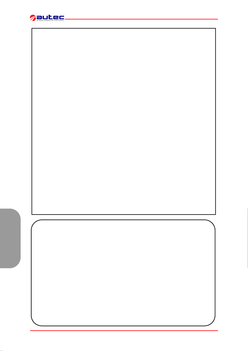
La documentation jointe à chaque radiocommande est composée au moins de:
- manuel de l'unité de transmission
- manuel de l'unité de réception
- manuel du chargeur de batteries
- déclaration de conformité CE
- certificat de garantie
- fiche technique
- annexe “Limitations & Autorisations”.
Vérifier que ces documents soient bien joints: en cas contraire, en faire la demande à Autec en spécifiant le numéro de série de la radiocommande.
Les conditions concernant la garantie de la radiocommande sont indiquées sur le
“Certificat de Garantie” contenu dans le présent manuel.
Les parties électroniques ayant 3 ans de garantie sont: E16STXEU_,
E16SRXEU_ et E16SCHEU_.
La fiche technique représente le schéma de câblage entre l’unité de réception et
la machine. Elle doit être remplie et contrôlée par l’installateur qui est responsable
du bon câblage. Après avoir effectué ces vérifications nécessaires, l'installateur
doit signer la fiche technique qui doit rester annexée au manuel d'utilisation (au cas
où on l'utiliserait pour des démarches administratives, toujours en conserver un
exemplaire).
Les données d'identification et d'homologation de la radiocommande sont reportées sur des plaquettes prévues à cet effet présentes sur les trois unités.
Ces plaques NE DOIVENT pour aucune raison être enlevées de leur emplacement
ou abîmées, sous peine de faire déchoir la garantie.
INSTRUCTIONS POUR LA GESTION DES DOCUMENTS
CERTIFICAT DE GARANTIE
FICHE TECHNIQUE
PLAQUE D'IDENTIFICATION
DONNEES TECHNIQUES SERIE MODULAR
Bande de fréquences .............................................................. 434.040-434.790 MHz
........................................................................................ * ou 433.050-434.790 MHz
...................................................................................... * ou 869.700 - 870.000 MHz
Canaux radio utilisables ................................................... 16 (434.040-434.790 MHz)
Français
......................................................................................... 32 (433.050-434.790 MHz)
....................................................................................... 12 (869.700 - 870.000 MHz)
Canalisation utilisée ......................................................................................... 25kHz
Distance de Hamming............................................................................................. ≥8
Probabilité de non détection des erreurs.................................................. <10 exp-11
Rayon d’action typique...................................................................................... 100 m
Temps de résponse des commandes ......................................................... < 100 ms
Temps de résponse de STOP..................................................................... < 100 ms
Temps d’urgence passive ....................................................................... ** 0,5/1 sec.
* voir annexe “Limitations & Autorisations” pour choisir la bande de travail consentie et le paragraphe 7 "Fre-
quences" pour l'éventuelle mise au point.
** voir paragraphe “Reglages” du manuel de l'unité de réception, programmations DIP n°1.
Page 46 de 71 2 - Introduction LIMJNMU0
Page 49
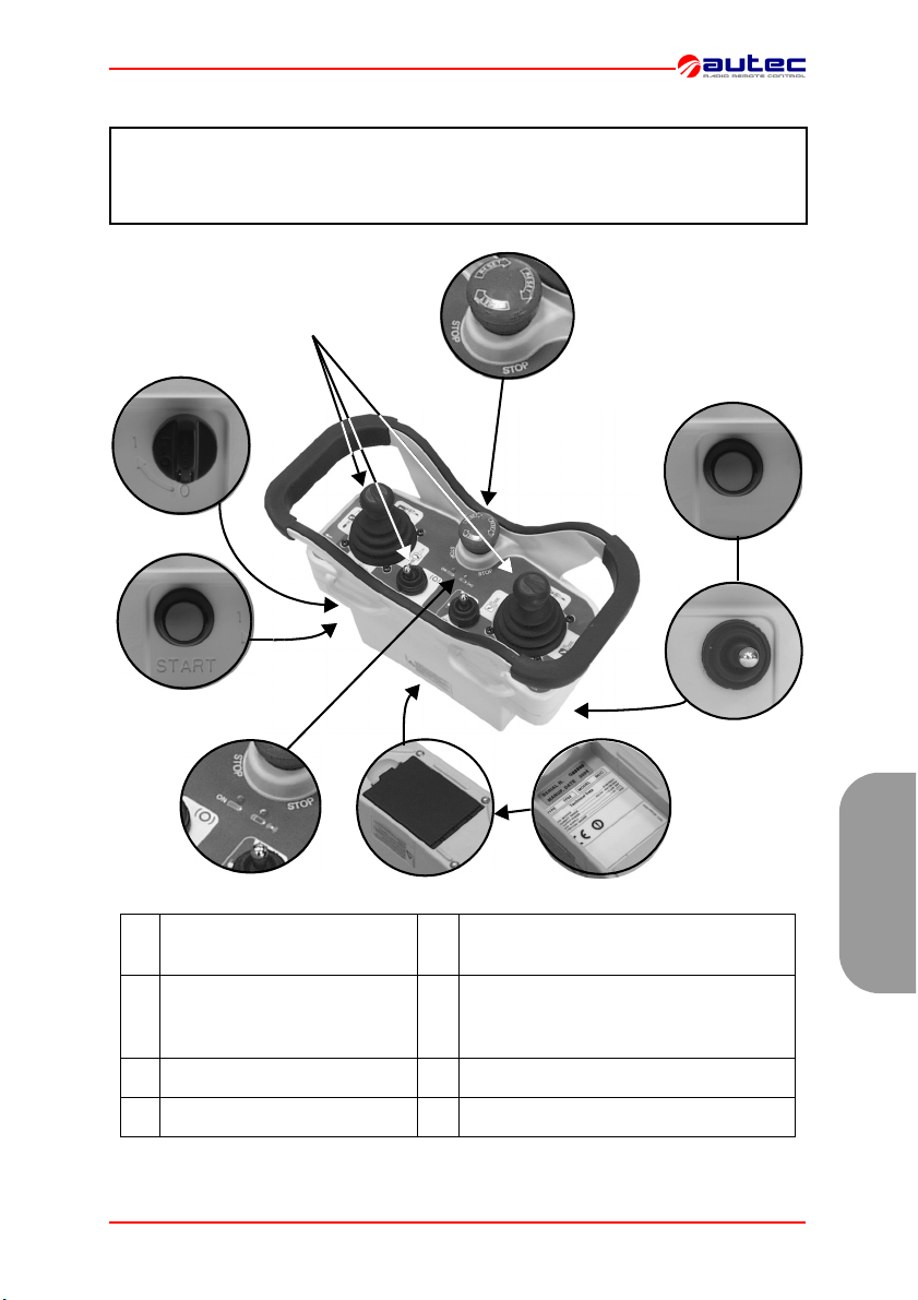
3 UNITÉ DE TRANSMISSION MJ
Ces unités de transmission peuvent être utilisées avec une des unités de réception
suivantes:
- Type R102
- Type R202
.
A
H
B
C
D
actionneurs (joystick ou
A
B clé d’allumage F
C bouton de START G bouton et/ou sélecteurs (optionnel)
D voyant de signalisation H bouton de STOP
LIMJNMU0 3 - Unité de Transmission MJ Page 47 de 71
sélecteurs)
E
F
E batterie (sur le fond)
données technique plaque (dans le
compartiment batterie) et plaque d’iden-
G
tification
Français
Page 50

Les unités de transmission de la série Modular sont équipées d'un double contrôle
qui protège le système “radiocommande+machine”, en position neutre (de repos),
contre les mouvements involontaires dus à d'éventuelles pannes de la radiocommande.
.
DONNEES TECHNIQUES UNITE DE TRANSMISSION MJ
Alimentation (piles MBM06MH).......................................................... * NiMH 7,2 Vdc
Antenne........................................................................................................... interne
Boîtier .................................................................................................. PA 6 (20% fg)
Degré de protection............................................................................................. IP65
Température de service ....................................................................... -20°C - +55°C
Dimensions.................................................................................. (255x170x126 mm)
Poids ................................................................................................................. 1,3 kg
Puissance unité de transmission (fréquence 433 MHz) ....................... < 10 mW ERP
Puissance unité de transmission (fréquence 870 MHz) ......................... < 5 mW ERP
Autonomie avec batterie déchargée (à 20°C) ............................................ 14 heures
Temps avertissement batterie déchargée ...................................................... 3,5 min
* Voir les données technique de la batterie dans le manuel du chargeur de batterie.
Français
Page 48 de 71 3 - Unité de Transmission MJ LIMJNMU0
Page 51

.
4 CONSEILS POUR L’EMPLOI
!
L’OPERATEUR
DEVRA
TOUJOURS:
SUIVRE DE VUE tous les mouvements de la machine et du chargement restant à l'intérieur du rayon d'action typique.
Se PLACER dans les meilleures conditions de visibilité directe du
système “machine + radiocommande” et surtout du chargement.
Avant de commencer à utiliser la radiocommande toujours VERIFIER
le bon fonctionnement mécanique du bouton-poussoir de STOP: S'il
ne fonctionne pas, ne pas utiliser la radiocommande.
ETEINDRE l'unité de transmission quand on suspend le travail, en
évitant de laisser le chargement suspendu (même durant la substitution de la batterie déchargée).
Ne JAMAIS laisser l’unité de transmission sans surveillance avec la
clé d’allumage insérée.
NE PAS ALLUMER OU NE JAMAIS ACTIONNER l'unité de transmission, sauf pour commencer à travailler: l'utilisation impropre pourrait causer des situations de danger.
NE PAS ALLUMER OU NE JAMAIS ACTIONNER l'unité de transmission dans des endroits fermés hors de vue ou hors du rayon typique
d'action.
INTERVENIR immédiatement en actionnant le bouton-poussoir de
STOP quand on rencontre une situation de risque.
FAIRE ATTENTION à toute la zone de travail, intervenant en cas de
danger, en actionnant manuellement le bouton poussoir de STOP.
FAIRE ATTENTION que sur l'unité de transmission ne se dépose
aucun matériau (comme du ciment, du sable, de la chaux,...) qui
pourrait en compromettre l'utilisation et la sécurité.
En présence de dysfonctionnement, de pièces endommagées et de
pannes, METTRE hors service la radiocommande jusqu'à ce que le
problème soit complètement éliminé.
LIMJNMU0 4 - Conseils pour l’emploi Page 49 de 71
Français
Page 52

5 CONSEILS POUR L’ENTRETIEN
!
DURANT TOUTES LES OPERATIONS D'ENTRETIEN, S'ASSURER QUE LA BATTERIE SOIT ENLEVEE DE L'UNITE DE TRANSMISSION.
Les éventuelles pannes peuvent être réparées exclusivement par du personnel autorisé Autec, en
utilisant seulement des pièces de rechange originales Autec.
L'unité de transmission n'a besoin d'aucun entretien particulier, toutefois pour travailler
avec une unité toujours efficace et sure, il faut:
AVANT L'EMPLOI:
- vérifier que l'unité soit intègre,
- contrôler que les garnitures, les soufflets et les capuchons des actionneurs (joystick, sélecteurs et boutons-poussoirs) soient intègres, souples et élastiques, et que les symboles
du panneau soient bien visibles.
APRES L'EMPLOI:
- toujours l'emmagasiner en milieu propre et sec,
- s'assurer que le logement et les contacts de la batterie soient propres,
- enlever la poussière ou les accumulations d'autre matériau de l'unité de transmission
à l'aide d'un chiffon humidifié avec de l'eau (pour nettoyer ne jamais utiliser de solvants
ou de produits inflammables/corrosifs et ne pas utiliser de nettoyeurs à jet d’eau à haute pression ou d’appareils à vapeur).
SERVICE D’ASSISTANCE
Pour tout cas d'entretien extraordinaire (réparation de la radiocommande et substitution de pièces endommagées ou en panne), faire exclusivement appel au service
après-vente. Pour permettre une intervention plus rapide et plus efficace, communiquer les données pour une identification correcte et complète de la radiocommande:
- numéro de matricule
- date d'achat (reportée sur le certificat de garantie)
Français
- anomalie constatée
- adresse et numéro de téléphone du lieu où elle est utilisée
- nom du responsable à contacter
- entreprise fournisseur.
Avant de faire intervenir les techniciens du service après-vente, il faut vérifier
d'avoir effectuer correctement toutes les instructions reportées.
ELIMINATION
Pour l’éliminer confier la radiocommande au service de récupération différenciée de la
ferraille qui existent sur le territoire.
Page 50 de 71 5 - Conseils pour l’entretien LIMJNMU0
Page 53

6
FONCTIONNEMENT DE L’UNITÉ
ALLUMAGE
Pour allumer l'unité de transmission, insé-
rer la clé d'allumage et la tourner dans la
position "I".
Pour mettre les fonctions de la radiocom-
mande en marche, actionner le bouton-
poussoir de “START” pendant 1-2 secon-
des.
Après le démarrage, le led de signalisation
s’allume toujours.
ET MISE EN MARCHE
DE TRANSMISSION MJ
ACTIVATION DES COMMANDES
Agir sur les actionneurs à joystick et/
ou à sélecteur concernant une commande quelconque de mouvement
ou de sélection qu'on entend effectuer.
SIGNALISATIONS
TYPE SIGNIFICATION INTERVENTION
clignotement voyant verte FONCTIONNEMENT NORMAL ///
clignotement voyant
rouge, accompagné
d'une sonnerie intermit-
tente du buzzer
lumière continue voyant
rouge au démarrage,
accompagnée d'une son-
nerie continue du buzzer
LIMJNMU0 6 - Fonctionnement de l’unité de transmission MJ Page 51 de 71
BATTERIE DÉCHARGÉE l’unité
de transmission s'étend après
environ 3,5 minutes du début du
clignotement du voyant
UN OU PLUSIEURS ACTIONNEURS (de mouvement) et/ou
BOUTON DE STOP INSERES
Éteindre l’unité de
transmission et substi-
tuer la batterie
Débrancher le/les
actionneurs et bouton-
poussoir de STOP
Français
Page 54
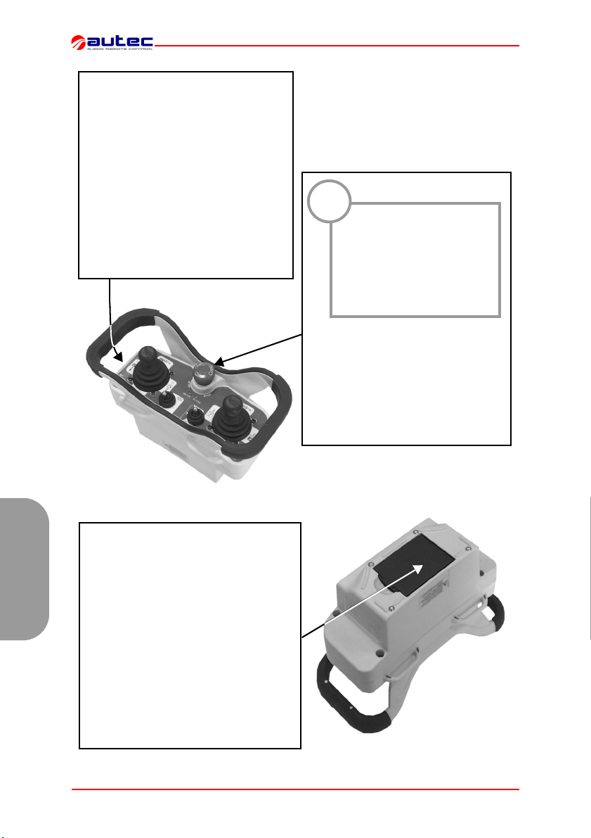
EXTINCTION
L'unité de transmission doit être
éteinte chaque fois qu'on suspend le
travail en tournant la clé d'allumage
en position "O" et en l'extrayant (toujours la déposer en lieu sûr).
L'extinction de l'unité de transmission
peut aussi advenir quand la batterie
n'est pas suffisamment chargée et/ou
quand la radiocommande n'est pas utilisée pendant 3 minutes et demie (voir paragraphe 8 "Reglages" programmations
DIP n°1).
!
Le bouton de STOP doit
être utilisé quand il faut
arrêter immédiatement
la machine si on constate une condition quelconque de danger.
Pour arrêter immédiatement la machine, appuyer sur le bouton de STOP.
Pour reprendre le travail, après avoir
vérifié que les conditions de travail
sont sures, tourner le bouton de STOP
dans le sens indiqué pour le désactiver et répéter la procédure de mise en
route.
STOP
Pour charger une batterie déchargée, suivre la procédure suivante:
1. L’insérer dans le chargeur de batterie
Français
prévu à cet effet placé dans un lieu dont la
température est comprise entre +5°C et
+45°C: le chargement de la batterie commence alors signalé par l’allumage du
voyant “CHARGE”.
2. Après 3 heures au maximum, le témoin
"CHARGE" s'éteint: la batterie est chargée. L'extraire du chargeur de batteries (si
elle n'est pas extraite, la charge continue
avec un courant de maintien).
Page 52 de 71 6 - Fonctionnement de l’unité de transmission MJ LIMJNMU0
BATTERIE
Page 55
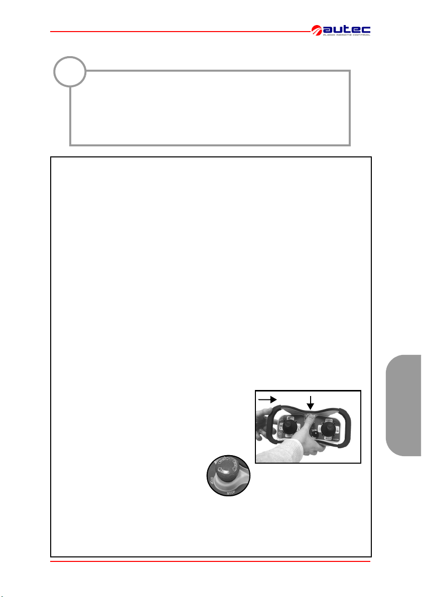
7 FREQUENCES
!
Dans les Etats européens l'utilisation des fréquences sur la bande
869.700 - 870.00 MHz a été harmonisée, ce que a été pas pour la bande 433.050 - 434.790 MHz.
Vérifier les éventuelles limitations dans le pays d'utilisation.
Par exemple certains pays européens permettent l'utilisation de ces
appareils radio seulement sur la bande 434.040 - 434.790 MHz.
Dans les radiocommandes AUTEC la fréquence radio de travail appartient à l'ensemble des fréquences admises par les normatives européennes en vigueur au
moment de l'introduction sur le marché.
Une radiocommande est programmée en modalité de balayage AUTOMATIQUE (programmation standard du constructeur) ou en modalité de sélection MANUELLE.
MODALITE DE SELECTION MANUELLE
Opérer en modalité de sélection MANUELLE permet de travailler à une fréquence spécifique qui doit être programmée manuellement à l'aide des dip switches présents
dans les modules radio (voir paragraphe 8 "Reglages").
Pour programmer ou modifier cette modalité de fonctionnement, contacter le
personnel autorisé par Autec.
Opérer en modalité de balayage AUTOMATIQUE permet de fonctionner à une fréquence spécifique qui, en cas d'interférence ou de conflit avec d'autres installations
radio, peut être changée par la procédure “Changement de la fréquence de travail”.
Cette modalité permet de n'intervenir ni à l'intérieur de l'unité transmission ni à l'intérieur de l'unité de réception.
1 Avec l'unité de transmission en marche (led verte clignotante):
- appuyer sur le bouton-poussoir de START sans le
relâcher (a)
- appuyer ensuite sur le bouton-poussoir de STOP (b)
- puis relâcher le bouton-poussoir de START.
2 Tourner le bouton de STOP dans le
sens indiqué pour le désactiver et répéter la procédure de mise en route.
N.B.: Voyant la séquence de changement de la fréquence de travail, l’unité de réception perd la liaison radioélectrique avec l’unité de transmission. Après la mise en marche, il peut falloir quelques secondes pour le rétablissement de la liaison: maintenir
alors le bouton-poussoir de START actif pendant environ 8-10 secondes.
LIMJNMU0 7 - Frequences Page 53 de 71
MODALITE DE BALAYAGE AUTOMATIQUE
Procédure de changement de la fréquence de travail
a
b
Français
Page 56
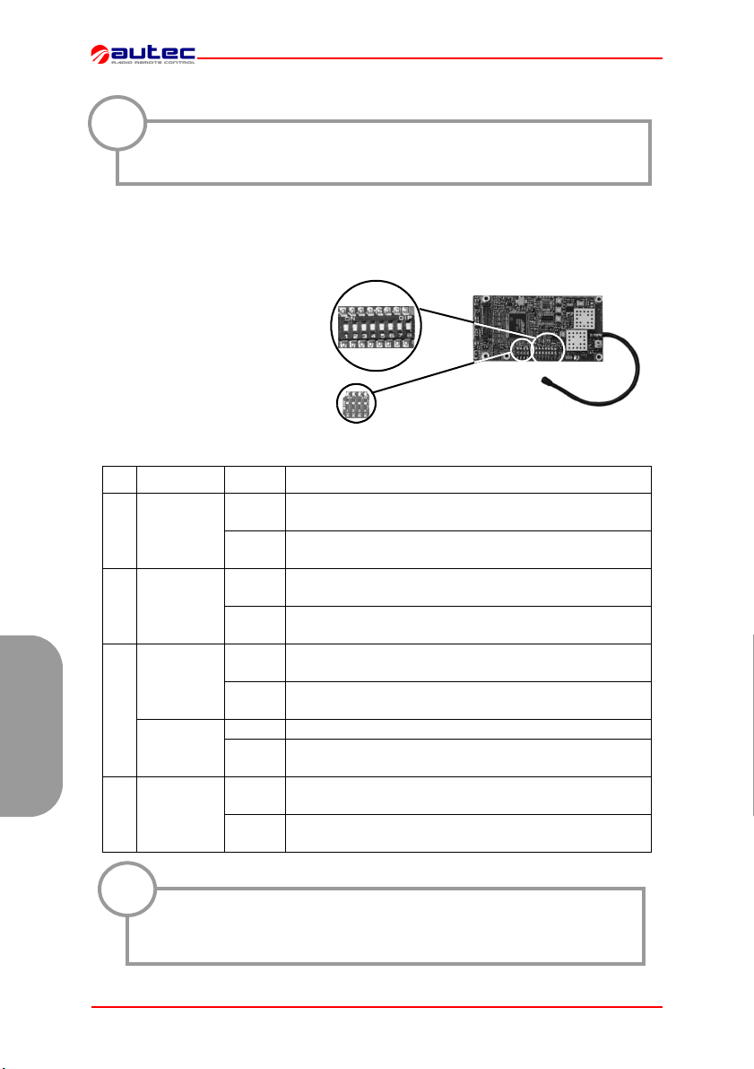
8 REGLAGES
La programmation des dip switch doit être effectuée avec l'unité de
!
transmission sans batterie et peut être effectué exclusivement par
du personnel autorisé.
DIP SWITCH DANS LE MODULE RADIO ÉMETTEUR E16STXEU_
Le groupe de huit dip switches
présent dans le module sert à
programmer certaines fonctions
et à programmer la fréquence de
travail.
Vice versa, il ne faut jamais modifier la programmation établie
dans l'autre groupe présent de
quatre dip switches.
DIP MODULE POS DESCRIPTION
1 E16STXEU_
2 E16STXEU_
E16STXEU1
3
E16STXEU2
Français
8 E16STXEU_
Groupe de 8
dip switches
Groupe de 4
dip switches
Groupe de 8 dip switches
ON
OFF
ON
OFF
ON
OFF
ON NE PAS UTILISER
OFF
ON
OFF
L’unité de transmission ne s’éteint pas de façon auto-
nome.
L’unité de transmission allumée sans commandes insé-
rées s’éteint après 3 minutes et demie
Désactivation de l’avis de batterie déchargée grâce au
Klaxon de la machine
Activation de l’avis de batterie déchargée grâce au
Klaxon de la machine
Modalité de balayage automatique des fréquences dans
bande 433.050 - 434.040 MHz
Modalité de balayage automatique des fréquences dans
bande 434.040 - 434.790 MHz
Modalité de balayage automatique des fréquences dans
bande 869.700 - 870.000 MHz
Modalité de sélection manuelle des fréquences
(DIP 3 - DIP 7 voir “FREQUENCY TABLE” page 71)
Modalité de sélection et balayage automatique des fré-
quences (DIP 3 - DIP 7 OFF)
!
Ces huit dip switches doivent être programmés comme le groupe de
8 dip switches (sauf le DIP 1) du module radio de l'unité de réception
(voir manuel).
Page 54 de 71 8 - Reglages LIMJNMU0
Page 57
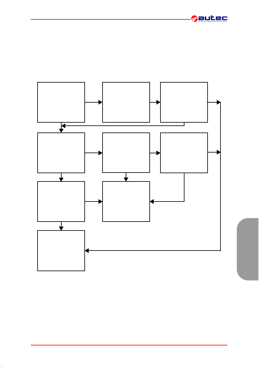
9 DIAGNOSTIC DE L’UNITE DE TRANSMISSION MJ
Au cas où le système “machine + radiocommande” ne se mettrait pas en marche il faudrait
contrôler si le problème concerne la radiocommande ou la machine. Avant toute vérification
et à l'aide du poste de commande câblé, contrôler aussi le fonctionnement de la machine:
- si elle ne démarre pas, le problème intéresse la machine elle-même
- si elle démarre, le problème concerne la radiocommande. Dans ce cas, procéder de la
façon suivante:
En actionnant
START, la voyant
rouge est allumée
avec lumière
continue, et le
buzzer sonne?
NON
La voyant rouge
clignote et le
buzzer sonne?
NON
La voyant verte
clignote
lentement?
NON
Si le problème
persiste
APPELER LE
SERVICE APRES
VENTE
Le bouton de
OUI
STOP ou un des
actionneurs de
mouvement est
inséré. Le/les
déclencher
La batterie est déchar-
gée: la remplacer par
OUI
une batterie sûrement
chargée. Elle continue
à clignoter rapidement
et le buzzer sonne?
Effectuer les
OUI
opérations de
diagnostique
concernant l'unité
de réception.
NON
La voyant est
allumée avec une
lumière fixe?
Les voyant
présentes sont
OUI
toujours toutes
éteintes ou
s'allument de façon
irrégulière?
OUI
NON
OUI
NON
Français
LIMJNMU0 9 - Diagnostic de l’unite de transmission MJ Page 55 de 71
Page 58

Français
Page 56 de 71 LIMJNMU0
Page 59

1 INDICE Y CONVENCIONES
ÍNDICE
1 Indice y convenciones ................................................................................................... 57
2 Introducción................................................................................................................... 58
3 Unidad transmisora MJ.................................................................................................. 61
4 Advertencias de empleo................................................................................................ 63
5 Advertencias para el mantenimiento ............................................................................. 64
6 Funcionamiento unidad transmisora MJ........................................................................ 65
7 Frecuencias...................................................................................................................67
8 Regulaciones................................................................................................................. 68
9 Diagnóstica unidad transmisora MJ .............................................................................. 69
CONVENCIONES
En este manual, todas las informaciones importantes se indican con las siguientes simbologías:
!
abcd....
abcd.... abcd....
ESTE MANUAL SIRVE COMO REFERENCIA EXCLUSIVAMENTE PARA LA UNIDAD
TRANSMISORA: LAS ADVERTENCIAS RELATIVAS A LA INSTALACIÓN DEL TELEMANDO DE RADIO SE ENCUENTRAN EN EL MANUAL DE LA UNIDAD RECEPTORA.
EL PRESENTE MANUAL SE DEBE LEER ATENTAMENTE Y SER COMPRENDIDO
POR TODAS LAS PERSONAS ENCARGADAS DE LA INSTALACIÓN, MANEJO Y MANUTENCIÓN ANTES DE INSTALAR, PONER EN FUNCIÓN O DE MANEJAR EL TELEMANDO.
LIMJNMU0 1 - Indice y convenciones Página 57 de 71
: ADVERTEN-
CIAS
: DATOS TÉCNI-
COS
abcd....
: INSTRUC-
CIONES
: TEXTOS
IMPORTAN-
TES
Español
Page 60

2 INTRODUCCIÓN
Los telemandos industriales de la serie Modular se
emplean para radio-dirigir máquinas por control remoto. Cada telemando industrial está constituido
por una unidad transmisora portátil, desde la que,
el operador puede dirigir a distancia la máquina y
por una unidad receptora instalada en la máquina.
La unidad transmisora, a través de una transmisión
de radio frecuencia envía un mensaje codificado.
En este mensaje se encuentra un valor denominado dirección (address). Cada unidad receptora
puede descodificar exclusivamente los mensajes
que provienen de la unidad transmisora que posee
la misma dirección.
Esto excluye que una interferencia pueda activar
cualquier función del sistema. De hecho, si la
transmisión a radio frecuencia resulta disturbada,
equivocada o interrumpida la unidad receptora detiene automáticamente todo el sistema.
Cada telemando de la serie Modular es conforme
a la directiva R&TTE 99/05/CE y a sus requisitos esenciales.
Cada telemando es además conforme a las normas
que se indican en la declaración de conformidad CE anexa a este manual.
Unidad
Tra nsm is ora
Unidad
Receptora
!
Autec no se asume ninguna responsabilidad si el telemando ha sido
instalado en aplicaciones diferentes de aquellas consentidas
Máquinas para la elevación de materiales (grúas, puentes grúa industriales, máquinas para la manipulación de materiales en general...).
Máquinas que hayan sido instaladas en ambientes en los que sea necesarios equipamientos con características antideflagrante y máquinas para la maniobra, elevación y el transporte de personas.
APLICACIONES PERMITIDAS
APLICACIONES NO PERMITIDAS
Español
Página 58 de 71 2 - Introducción LIMJNMU0
Page 61

!
Se recuerda que en algunos Estados se deben respetar leyes que reglamentan:
- la utilización y la posesión de un telemando
- el empleo de las frecuencias de funcionamiento que no se han
aprobado todavía en los estados europeos.
En el anexo "Limitaciones y Autorizaciones" de este manual, se pueden encontrar todas las indicaciones que hay que observar.
Como requerido por la Directiva de Máquinas y de sus relativas armonizadas, hay que
realizar por cada máquina un análisis de los riesgos: por lo tanto, en caso de empleo
de un telemando, hay que valuar con el análisis de la máquina si la máquina se puede
teledirigir o no.
Este análisis es responsabilidad del fabricante de la máquina misma o de quién decide
instalar y utilizar el telemando.
Autec no se asume ninguna responsabilidad si este análisis de riesgos no se ha
efectuado de modo correcto.
Para poder garantizar el funcionamiento correcto del telemando, se tienen que respetar siempre todas las instrucciones sobre la seguridad en el trabajo y sobre la prevención de accidentes en el trabajo. Además HAY que observar todas las leyes
nacionales relativas tanto al uso de la máquina como del telemando que estén en vigor en el estado donde se utilice el sistema.
Autec no podrá asumirse alguna responsabilidad si se emplea el telemando en
condiciones de trabajo fuera norma.
LIMITACIONES & AUTORIZACIONES
En caso de emergencia o avería HAY que poner fuera de servicio el
!
sistema “máquina + telemando” hasta eliminar por completo el problema existente.
Eventuales partes dañadas pueden ser sustituidas EXCLUSIVAMENTE
por personal autorizado Autec, usando únicamente piezas de repuesto
originales Autec.
LIMJNMU0 2 - Introducción Página 59 de 71
Español
Page 62

La documentación anexa a cada telemando está compuesta de almenos:
- manual de la unidad transmisora
- manual de la unidad receptora
- manual del cargador de la batería
- la declaración de conformidad CE
- certificado de garantía
- ficha técnica
- anexo “Limitaciones & Autorizaciones”.
Comprobar que se hallen estos documentos anexos: si no fuera así, solicitarlos a Autec especificando el número de matrícula del telemando.
Las condiciones que regulan la garantía del telemando se indican el “Certificado
de Garantía” que contiene este manual.
Las partes electrónicas con 3 años de garantía son: E16STXEU_,
E16SRXEU_ y E16SCHEU_.
La ficha técnica representa el diagrama de conexionado entre la unidad de recepción y la máquina. Esta tiene que ser rellenada y controlada por el instalador, éste
tiene la responsabilidad de efectuar el conexionado correcto. Efectuadas estas
comprobaciones necesarias, el instalador tiene que firmar la ficha técnica que
debe permanecer anexa al manual de empleo (en el caso en que ésta se utilice
para prácticas administrativas hay que tener siempre una copia).
Los datos de identificación y homologación del telemando están indicados en la adecuada placa, ya sea sobre la unidad de transmisión o sobre la unidad de recepción.
Dichas placas NO SE TIENEN que quitar de su posición o dañar nunca por
ningún motivo, en caso contrario, la pena es la resolución de la garantía.
INSTRUCCIONES PARA LA GESTIÓN DE DOCUMENTOS
CERTIFICADO DE GARANTÍA
FICHA TÉCNICA
PLACAS DE IDENTIFICACIÓN
Banda de frecuencias............................................................ 434.040 - 434.790 MHz
......................................................................................... * o 433.050 - 434.790 MHz
......................................................................................... * o 869.700 - 870.000 MHz
Canales de Radio disponibles........................................ 16 (434.040 - 434.790 MHz)
....................................................................................... 32 (433.050 - 434.790 MHz)
....................................................................................... 12 (869.700 - 870.000 MHz)
Ancho de banda ............................................................................................... 25kHz
Distancia de Hamming ............................................................................................ ≥8
Probabilidad de fallo en la detección de error.......................................... <10 exp-11
Alcance.............................................................................................................. 100 m
Tiempo de respuesta de los mandos .......................................................... < 100 ms
Tiempo de respuesta de STOP................................................................... < 100 ms
Tiempo de emergencia pasiva ................................................................ ** 0,5/1 sec.
* ver anexo “Limitaciones & Autorizaciones" para elegir la banda de funcionamiento consentida y elpárrafo 8
Español
"Regulaciones" para su posible restablecimiento.
** ver párrafo “Regulaciones" del manual de la unidad receptora, regulaciones DIP nº 1.
Página 60 de 71 2 - Introducción LIMJNMU0
DATOS TÉCNICOS
Page 63

3 UNIDAD TRANSMISORA MJ
Estas unidades transmisoras se pueden emplear con una de las siguientes unidades
receptoras:
- Type R102
- Type R202
.
A
H
B
C
D
actuadores (joystick o selec-
A
B llave de encendido F
C pulsador de START G pulsador y/o selector (opcional)
D led de señalización H pulsador de STOP
LIMJNMU0 3 - Unidad transmisora MJ Página 61 de 71
tores)
E
F
E Batería (bajo)
placa de identificación y placa de datos
técnicos (en el alojamiento de la bate-
G
ría)
Español
Page 64
Las unidades transmisoras de la serie Modular están equipadas de un doble control
que protege el sistema "telemando+máquina", en posición neutra (de descanso), de
los movimientos involuntarios debidos a posibles averías del telemando.
.
DATOS TÉCNICOS UNIDAD TRANSMISORA MJ
Alimentación (batería MBM06MH) ..................................................... * NiMH 7,2 Vdc
Antena............................................................................................................. interna
Cubierta................................................................................................ PA 6 (20% fg)
Grado de protección............................................................................................ IP65
Temperatura de trabajo........................................................................ -20°C - +55°C
Medidas....................................................................................... (255x170x126 mm)
Peso .................................................................................................................. 1,3 kg
Potencia transmisora (frecuencia 433 MHz) ........................................ < 10 mW ERP
Potencia transmisora (frecuencia 870 MHz) .......................................... < 5 mW ERP
Autonomía con batería cargada (a 20°C)..................................................... 14 horas
Tiempo de preaviso batería descargada........................................................ 3,5 min
* ver los datos técnicos de la batería en el manual del cargador de la batería.
Español
Página 62 de 71 3 - Unidad transmisora MJ LIMJNMU0
Page 65
.
4 ADVERTENCIAS DE EMPLEO
!
EL OPERARIO
DEBERÁ
SEGUIR EN MODO VISIBLE todos los movimientos de la máquina y
de la carga permaneciendo al interior del radio de acción
COLOCARSE con la mayor visibilidad directa posible del sistema
“máquina + telemando “ y de la carga.
Antes de emplear el telemando hay que COMPROBAR siempre que
el funcionamiento mecánico del pulsador STOP sea correcto: si no
funcionase, no utilizar el telemando.
APAGAR la unidad transmisora cuando se suspenda el trabajo evitando que la carga permanezca en suspensión aun cuando se debe
efectuar la sustitución de la batería descargada.
NO DEJAR NUNCA sin vigilancia la unidad transmisión con la llave
de accionamiento
NO ENCENDER O ACCIONAR NUNCA la unidad transmisora sino
para empezar a trabajar: el empleo impropio puede causar situaciones de peligro.
NO ENCENDER O ACCIONAR NUNCA la unidad transmisora en lugares cerrados sin visibilidad o fuera del radio típico de acción.
INTERVENIR inmediatamente accionando el pulsador STOP cuando
se verifique una situación de peligro.
PRESTAR ATENCIÓN a toda el área de trabajo, interviniendo en caso
de peligro, accionando manualmente el pulsador STOP.
HAY QUE TENER CUIDADO en que no se deposite en la unidad
transmisora materiales (como cemento, arena, cal...) que puedan
perjudicar su utilización y seguridad.
Si se presentase un mal funcionamiento, partes dañadas y averías,
HAY QUE PONER fuera de servicio el telemando hasta que no se resuelva por completo el problema.
LIMJNMU0 4 - Advertencias de empleo Página 63 de 71
Español
Page 66
5 ADVERTENCIAS PARA EL MANTENIMIENTO
!
CERCIORARSE QUE DURANTE TODAS LAS OPERACIONES DE MANTENIMIENTO SE HAYA QUITADO LA
BATERÍA DE LA UNIDAD TRANSMISORA.
Las averías que pudieran surgir tendrán que ser reparadas exclusivamente por personal autorizado Autec, utilizando únicamente piezas de repuesto originales Autec.
La unidad transmisora no necesita particulares manutenciones, pero para poder trabajar con una unidad eficaz y segura hay que:
ANTES DE SU EMPLEO:
- comprobar el perfecto estado de la unidad transmisora,
- controlar las guarniciones, los fuelles y caperuzas de los actuadores (joystick, selectores y pulsadores) estén íntegros, sean suaves y elásticos y que los símbolos del panel sean bien visibles.
DESPUÉS DE SU EMPLEO:
- hay que almacenarla siempre en ambientes limpios y secos,
- comprobar que el alojamiento y los contactos de la batería de estén limpios,
- eliminar el polvo o la acumulación de otros materiales de la unidad transmisora con
un paño humedecido en agua (para limpiarlas no se debe emplear nunca disolventes
o productos inflamables o corrosivos y no se deben emplear hidrolimpiadoras a alta
presión o aparatos de vapor).
SERVICIO DE ASISTENCIA
En todos los casos de manutención extraordinaria (reparaciones del telemando y sustitución de los componentes dañados o averiados), contactar exclusivamente el servicio de Asistencia. Para que las intervenciones sean más rápidas y eficaces se deben
comunicar los datos para poder identificar correctamente y completamente el telemando:
- número de matrícula,
- fecha de adquisición (indicada en el certificado de garantía),
- el tipo de anomalía,
- dirección y número de teléfono del lugar donde se utiliza,
- nombre del responsable que se debe contactar,
- empresa proveedora.
Antes de hacer intervenir a los técnicos de la Asistencia, se tiene que comprobar que se hayan efectuado correctamente todas las instrucciones anexas.
Español
No tire el equipo a la basura. Para reciclar el equipo, enviar el telemando a un servicio
de reciclaje territorial.
Página 64 de 71 5 - Advertencias para el mantenimiento LIMJNMU0
RECICLAJE
Page 67
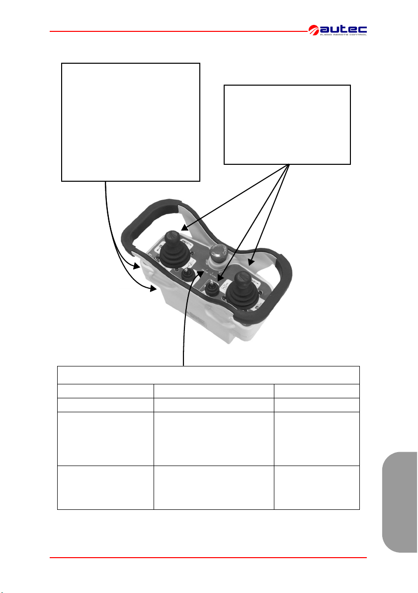
6 FUNCIONAMIENTO UNIDAD TRANSMISORA MJ
ENCENDIDO Y ACTIVACIÓN
Para poder acceder a la unidad
transmisora, hay que introducir la
llave de encendido y girarla en la posición "I".
Para activar las funciones del telemando, accionar el pulsador de
“START” por 1-2 segundos.
Después de la activación se encenderá un led de señalización.
Accionar los actuadores de
joystick o de selector relativos
a cualquier mando de movimiento o de selección que se
piensa realizar.
ACTIVACIÓN
DE LOS MANDOS
INDICACIONES
TIPO SIGNIFICADO INTERVENCIÓN
centelleo led verde FUNCIONAMIENTO NORMAL ///
BATERÍA DESCARGADA la
centelleo led rojo, acom-
pañado por el sonido
intermitente del buzzer
luz fija led rojo a la activa-
ción, acompañado por el
sonido continuado del
buzzer
LIMJNMU0 6 - Funcionamiento unidad transmisora MJ Página 65 de 71
unidad transmisora se apaga
después de unos 3 minutos y
medio desde que el led empieza
a centellear
UNO O MÁS ACTUADORES
(de movimiento) y/o PULSA-
DOR DE STOP INSERTADOS
Apagar la unidad
transmisora y sustituir
la batería
Desconectar el/los
actuador/es y pulsa-
dor de STOP
Español
Page 68
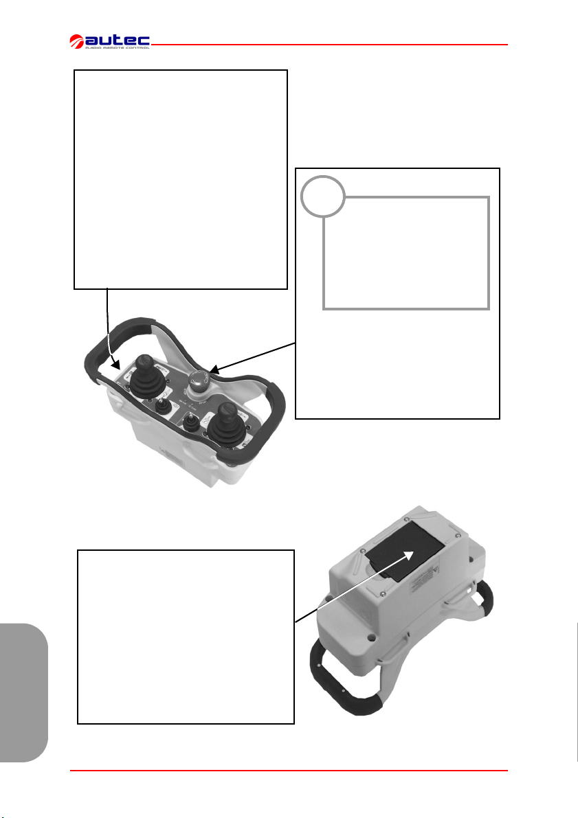
DESCONEXIÓN
La unidad transmisora se debe apagar cada vez que se suspenda el trabajo girando la llave de encendido en
la posición "O" y extrayéndola (hay
que colocarla siempre en un lugar seguro).
La desconexión de la unidad transmisora se puede producir también cuando la
batería no está suficientemente recargada o cuando no se emplee el radiomando por un tiempo superior a 3,5 minutos
(ver párrafo 8 "Regulaciones" regulaciones DIP nº 1.).
!
El pulsador de STOP se
utiliza cuando sea necesaria la parada inmediata de la máquina al
producirse cualquier situación de peligro
Para parar inmediatamente la máquina, presionar el pulsador de parada
STOP.
Para empezar de nuevo a trabajar, girar hacia el lado indicado el pulsador
de parada STOP para su desactivación y repetir el proceso de activación.
STOP
Para cargar las baterías, seguir los siguientes pasos:
1.introducirla en su cargador en un lugar
que tenga una temperatura de +5°C a
+45°C: la recarga empieza con la señalización del indicador luminoso “CHARGE”.
2. Después de 3 horas el indicador
"CHARGE" se apaga, la batería está cargada. Extraerla del cargador (si no se extrae, el cargador proporciona una pequeña
corriente de mantenimiento).
BATERÍAS
Español
Página 66 de 71 6 - Funcionamiento unidad transmisora MJ LIMJNMU0
Page 69
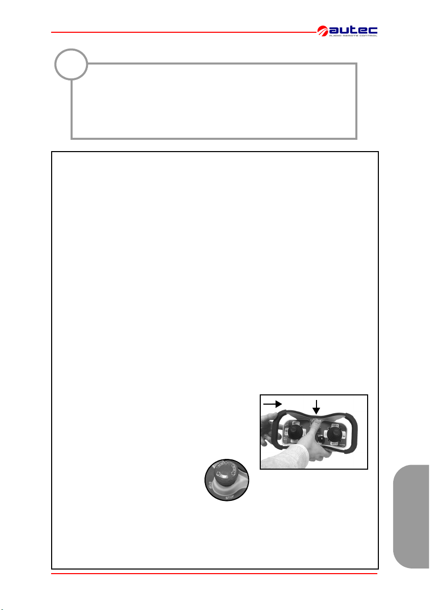
7 FRECUENCIAS
!
En los paises europeos, la banda de frecuencia 869.700 – 870.000
MHz está armonizada, al contrario la banda 433.050 - 434.790 MHz no
está armonizada. Comprobar las limitaciones eventuales según el
país en que se emplee.
Por ejemplo, algunos estados europeos permiten l'empleo de estos
aparatos radio sólo en la banda de frecuencia 433.050 - 434.790 MHz.
En los telemandos AUTEC la frecuencia radio de funcionamiento pertenece al
conjunto de frecuencias admitidas por las normativas europeas en vigor al momento de su introducción en el mercado.
El telemando viene programado por el fabricante en la modalidad de análisis AUTOMÁTICO (programación estándar del fabricante) o en la modalidad de selección MANUAL.
MODALIDAD DE SELECCIÓN MANUAL
Operar en la modalidad de selección MANUAL consiente trabajar en una frecuencia
específica que se debe programar de modo manual, regulando los dip switch que hay
en los módulos radio (ver párrafo 8 "Regulaciones").
Para programar o modificar esta modalidad de funcionamiento hay que contactar el
personal autorizado Autec.
Operar en la modalidad de barrido AUTOMÁTICO permite el funcionamiento en una
frecuencia específica que, en caso de interferencia o de conflicto con otros aparatos
radio, se puede cambiar con el proceso "Cambio de frecuencia de funcionamiento".
Tal modalidad no consiente la intervención al interno de la unidad transmisora,
ni de la unidad receptora.
1 Con la unidad transmisora activa (led verde cente-
lleante):
- presionar el pulsador START sin soltarlo (a),
- presionar sucesivamente el pulsador STOP (b),
- soltar por ultimo el pulsador START.
2 Girar hacia el lado indicado el pulsador de STOP para su desactivación y
repetir el proceso de activación.
Nota: Durante lo proceso de cambio de frecuencia de trabajo, la unidad de recepción
pierde la conexión radioeléctrica con la unidad de transmisión.
Después de la activación, pueden ser necesarios algunos segundos para la
reactivación de la conexión: mantener, por lo tanto, presionado el pulsador de
START de 8 - 10 segundos.
LIMJNMU0 7 - Frecuencias Página 67 de 71
MODALIDAD DE BARRIDO AUTOMÁTICO
Cambio de la frecuencia de trabajo
a
b
Español
Page 70
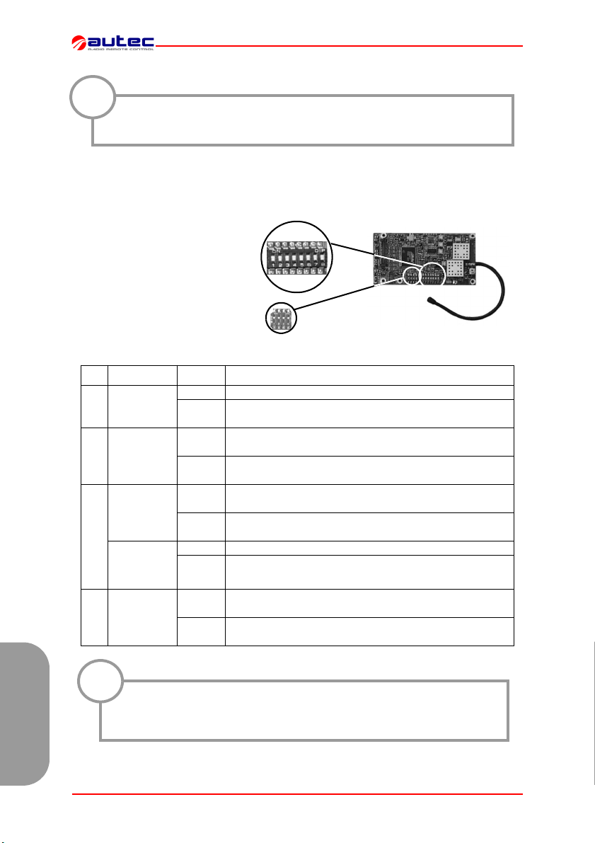
8 REGULACIONES
La programación de los dip switch se debe efectuar con la unidad
!
transmisora sin batería y debe ser efectuada par personal especializado.
DIP SWITCHES EN EL MÓDULO RADIO TRANSMISOR E16STXEU_
El grupo de ocho dip switches
que hay en el módulo sirve para
programar algunas funciones y
regular la frecuencia de trabajo.
Viceversa, no se deberá modificar nunca la programación regulada, en el otro grupo existente,
con cuatro dip switches.
Grupo di 8 dip switches
DIP MÓDULO POS. FUNCIÓN
ON La unidad transmisora no se apaga automáticamente
1 E16STXEU_
2 E16STXEU_
E16STXEU1
3
E16STXEU2
8 E16STXEU_
OFF
ON
OFF
ON
OFF
ON no utilizar
OFF
ON
OFF
La unidad transmisora encendida sin ningún mando
insertado se apaga después de 3,5 minutos
Desactivación del aviso de batería descargada a través
Activación del aviso de batería descargada a través del
Modalidad de barrido automático de la frecuencia en la
Modalidad de barrido automático de las frecuencias en la
Modalidad de barrido automático de las frecuencias en la
Modalidad de selección manual de las frecuencias
(DIP 3 - DIP 7 ver “FREQUENCY TABLE” pág. 71)
Modalidad de selección y de regulación automática de
las frecuencias (DIP 3 - DIP 7 OFF)
Grupo de 8
dip switches
Grupo de 4
dip switches
del claxon de la máquina
claxon de la máquina
banda 433.050 - 434.040 MHz
banda 434.040 - 434.790 MHz
banda 869.700 - 870.000 MHz
!
Estos ocho dip switches se deben programar como el grupo de 8
dip switches (excepto el DIP 1) del módulo radio de la unidad receptora (ver el manual).
Español
Página 68 de 71 8 - Regulaciones LIMJNMU0
Page 71
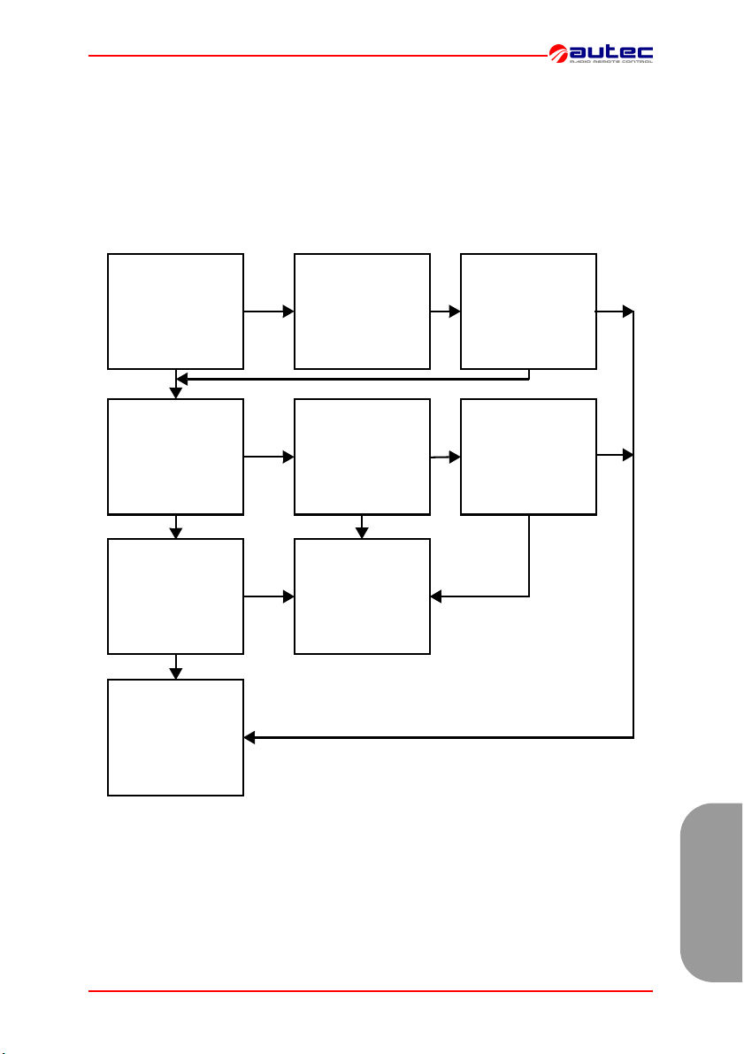
9 DIAGNÓSTICA UNIDAD TRANSMISORA MJ
En el caso en que el sistema “máquina + telemando” no se ponga en funcionamiento, es
oportuno controlar si el problema proviene del telemando o de la máquina. Por lo tanto, antes de llamar al servicio técnico comprobar que la máquina funcione correctamente con la
botonera de cable.
- si no se activase, el problema es de la máquina.
- si funciona, el problema es del telemando. En tal caso, actuar como se indica en el siguiente procedimiento:
¿Si se acciona
START, el led rojo
se enciende
con luz fija,
y el buzzer suena?
NO
¿El led rojo cente-
llea
y el buzzer suena?
NO
¿El led verde
centellea?
NO
Si el problema per-
siste LLAMAR AL
SERVICIO DE
ASISTENCIA TÉC-
NICA
El pulsador STOP
o uno de los pulsa-
SI
dores de maniobra
están encajados.
Desconectarlo / -s.
La batería está des-
cargada: sustituirla
SI
por otra que este bien
cargada. ¿Sigue centelleando rápidamente, y el buzzer suena?
Efectuar las opera-
SI
ciones de diagnos-
tico relativas a la
unidad receptora.
NO
¿El led está encendido con la luz fija, y
el buzzer suena?
Limpiar los contac-
tos de los alojamien-
SI
tos de la batería.
¿Sigue centelleando
rápidamente, y el
buzzer suena?
SI
NO
SI
NO
LIMJNMU0 9 - Diagnóstica unidad transmisora MJ Página 69 de 71
Español
Page 72

Español
Página 70 de 71 LIMJNMU0
Page 73
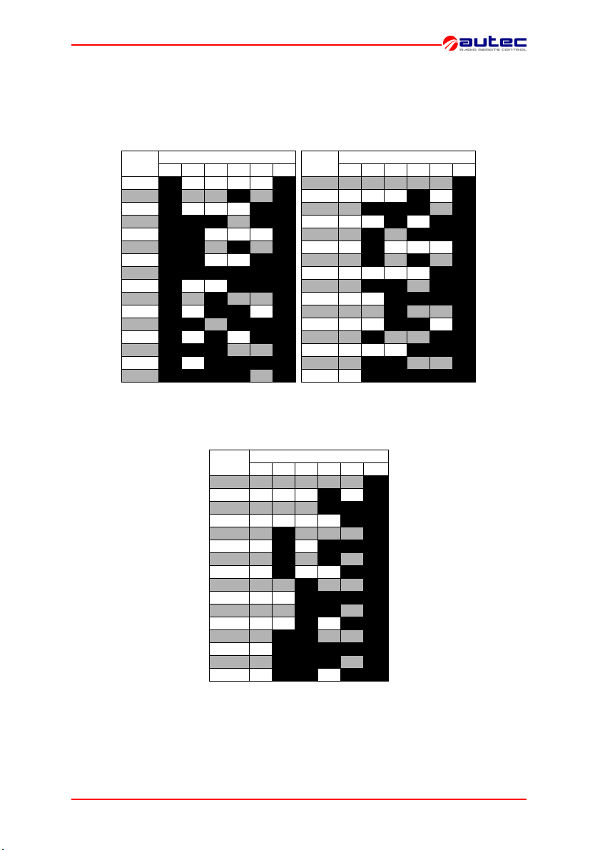
FREQUENCY TABLE
E16STXEU1 & E16SRXEU1
433.050 - 434.040 MHz
MHz
433.125 ON OFF OFF OFF OFF ON
433.200 ON OFF OFF ON OFF ON
433.250 ON OFF OFF OFF ON ON
433.325 ON ON ON OFF ON ON
433.400 ON ON OFF OFF OFF ON
433.425 ON ON OFF ON OFF ON
433.475 ON ON OFF OFF ON ON
433.500 ON ON ON ON ON ON
433.575 ON OFF OFF ON ON ON
433.625 ON OFF ON OFF OFF ON
433.700 ON OFF ON ON OFF ON
433.775 ON ON OFF ON ON ON
433.825 ON OFF ON OFF ON ON
433.900 ON ON ON OFF OFF ON
433.950 ON OFF ON ON ON ON
434.025 ON ON ON ON OFF ON
DIP SWITCH
345678
E16STXEU2 & E16SRXEU2
869.700 - 870.000 MHz
MHz
869.7125 OFF OFF OFF OFF OFF ON
869.7375 OFF OFF OFF ON OFF ON
869.7375 OFF OFF OFF ON ON ON
869.7625 OFF OFF OFF OFF ON ON
869.7875 OFF ON OFF OFF OFF ON
869.8125 OFF ON OFF ON ON ON
869.8125 OFF ON OFF ON OFF ON
869.8375 OFF ON OFF OFF ON ON
869.8625 OFF OFF ON OFF OFF ON
869.8875 OFF OFF ON ON ON ON
869.8875 OFF OFF ON ON OFF ON
869.9125 OFF OFF ON OFF ON ON
869.9375 OFF ON ON OFF OFF ON
869.9625 OFF ON ON ON ON ON
869.9625 OFF ON ON ON OFF ON
869.9875 OFF ON ON OFF ON ON
345678
434.040 - 434.790 MHz
MHz
434.100 OFF OFF OFF OFF OFF ON
434.125 OFF OFF OFF ON OFF ON
434.150 OFF ON ON ON OFF ON
434.225 OFF OFF ON OFF ON ON
434.300 OFF ON OFF ON ON ON
434.325 OFF ON OFF OFF OFF ON
434.350 OFF ON OFF ON OFF ON
434.375 OFF OFF OFF OFF ON ON
434.400 OFF ON ON OFF ON ON
434.475 OFF OFF ON ON ON ON
434.500 OFF OFF ON OFF OFF ON
434.525 OFF OFF ON ON OFF ON
434.600 OFF ON OFF OFF ON ON
434.675 OFF OFF OFF ON ON ON
434.700 OFF ON ON OFF OFF ON
434.725 OFF ON ON ON ON ON
DIP SWITCH
DIP SWITCH
345678
LIMJNMU0 FREQUENCY TABLE Page 71 of 71
71
 Loading...