

Page 1

Installation manual
GPRS Monitoring Gateway for Autarco inverters
© Autarco Group B.V. IM.S2.GPRS-GATEWAY.EN-V1.0
Page 2

2 GPRS Monitoring Gateway
Contact Information
Autarco Group B.V.
Schansoord 60
5469 DT Erp
The Netherlands
www.autarco.com
info@autarco.com
Other Information
This manual is an integral part of the unit. Please read the manual carefully before installation, operation or
maintenance. Keep this manual for future reference.
Product information is subject to change without notice. All trademarks are recognized as the property of their
respective owners.
If any technical problems occur, please contact us with the following information in hand.
- Device Model
- Serial number of product
© Autarco Group B.V.
All rights reserved.
Page 3

Installation manual
IM.S2.GPRS-GATEWAY.EN-V1.0 3
Table of contents
Introduction 4
1.
1.1 Read this first 4
1.2 Checklist 4
1.3 Interface and connection 5
1.4 Mounting gateway 5
2. Installing the GPRS Monitoring Gateway 6
2.1 Connection with single inverter 6
2.2 Connection with multiple inverters 7
2.3 Confirm connection 7
3. Setting up the SIM card 8
3.1 Unlock the security code on your SIM card 8
3.2 Install the SIM card 8
3.3 Configure the SIM card 8
4. Registration 9
4.1 Check connection in MyAutarco 9
4.2 Monitoring setup 9
5. Debug 10
5.1 LED indication 10
5.2 Trouble Shooting 11
5.3 Reset 11
Page 4
4 GPRS Monitoring Gateway
WARNING! Indicates safety instruction, which if not correctly followed, can result in injury or
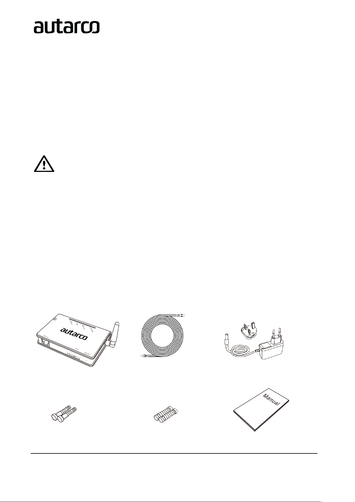
1 LAN Monitoring Gateway
1 power adapter with
European or British plug
1 Quick Guide
2 expandable rubber hoses
2 screws
1 RS485 Monitoring cable
1. Introduction
1.1 Read this first
The main purpose of this user manual is to provide instructions and detailed procedures for installing, operating,
maintaining, and troubleshooting the Autarco GPRS Monitoring Gateway which is used with Autarco inverters.
To reduce the risk of electrical shock, and to ensure the safe installation and operation of the GPRS Monitoring
Gateway, the following safety symbol appear sthroughout this document to indicate dangerous conditions and
important safety instructions:
property damages.
The GPRS Monitoring Gateway can collect information of PV-systems by GPRS communication through
RS485/422 interface with convenient 'plug and play' function.
Users can check the runtime status of the device by checking the 4 LEDs on the panel, indicating power,
485/422, link and status respectively.
Please keep this user manual available at all times.
1.2 Checklist
After unpacking the box, please make sure all the items are contained as follows:
(S2.GPRS-BOX)
Page 5
IM.S2.GPRS-GATEWAY.EN-V1.0 5
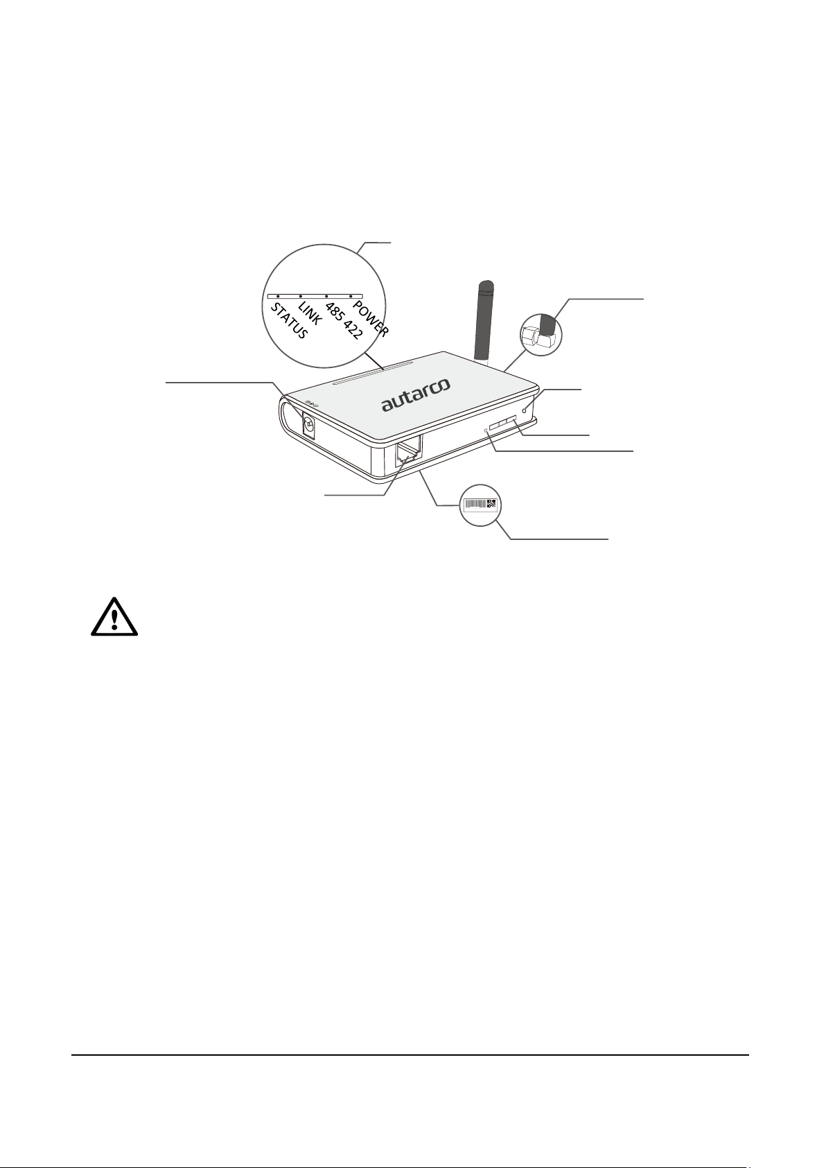
LEDs
Antenna Port
RESET
SIM card slot
SIM card ejection button
SN serial number
RS485/422
Power adapter port
1.3 Interface and connection
Installation manual
WARNING! When you screw/unscrew or adjust the antenna, please make sure that you only
use the metal part of the antenna. Do not hold the plastic part while adjusting otherwise the
antenna may be damaged.
1.4 Mounting gateway
GPRS Monitoring Gateway can be either wall-mounted or flatwise. It should at all times be installed indoors.
Page 6
6 GPRS Monitoring Gateway
2. Installing the GPRS Monitoring Gateway
WARNING! Power supply of inverters must be cut off before connection. Make sure that all
connections are completed, then power the gateway and inverters, otherwise personal injury
or equipment damage may be caused.
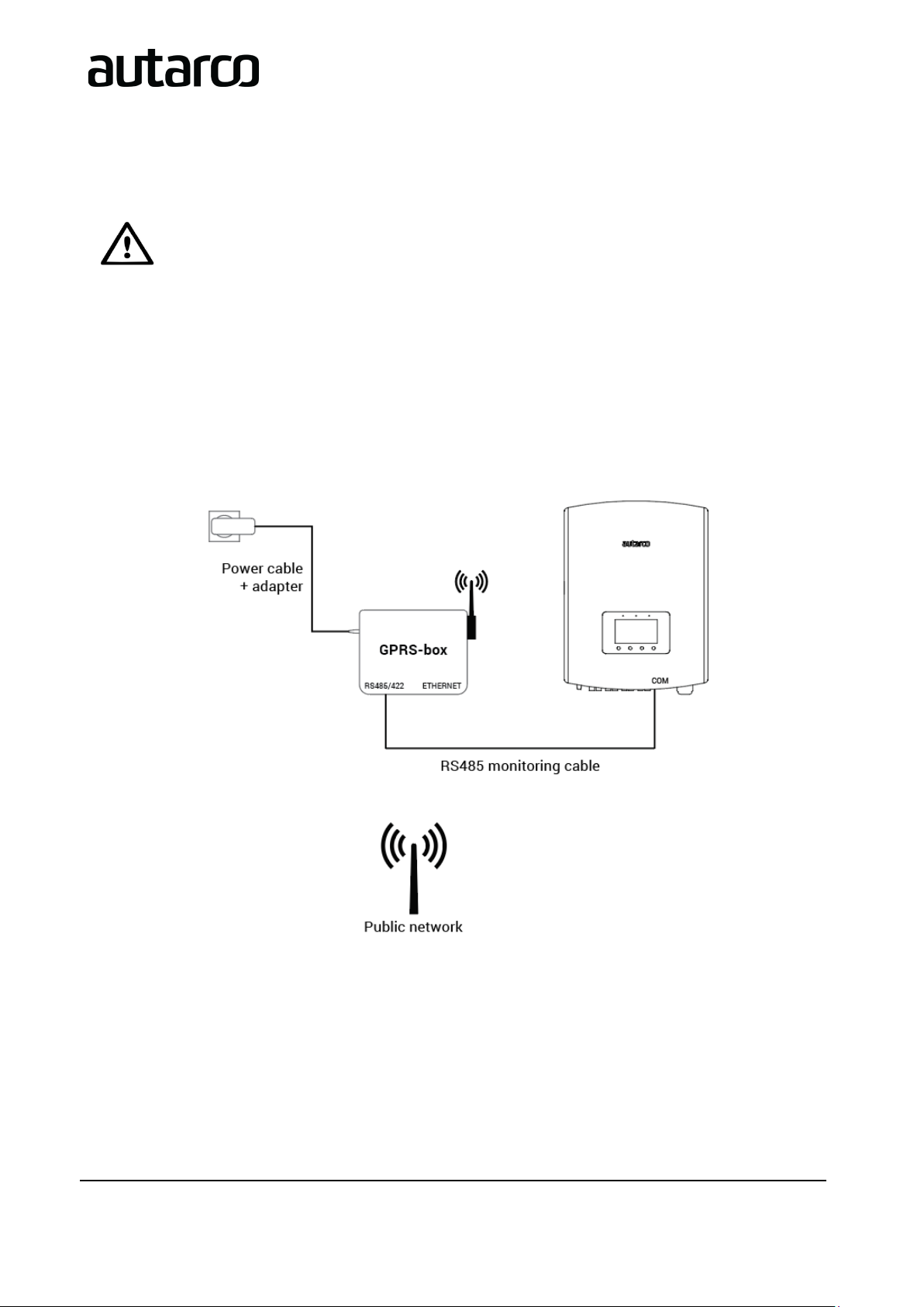
2.1 Connection with single inverter
Connect inverter to gateway with monitoring cable, and connect gateway to power supply with power adapter.
Page 7
Installation manual
IM.S2.GPRS-GATEWAY.EN-V1.0 7
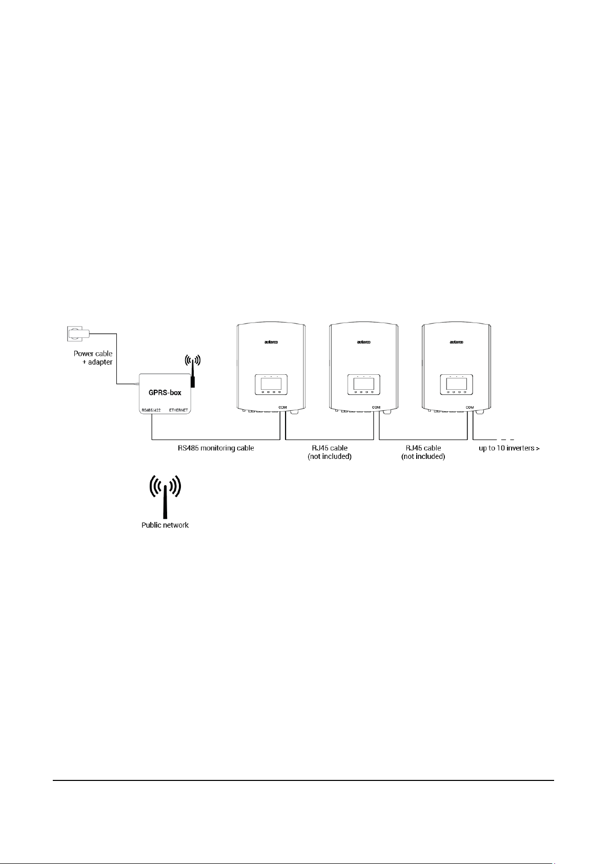
2.2 Connection with multiple inverters
1. Parallel connect multiple inverters with network cables.
2. Connect first inverter to gateway with monitoring cable.
3. Set different address for each inverter. For example, when connecting three inverters, the address of
first inverter must be set as "01", the second must be set as "02", and the third must be set as "03" and
so on.
a. On the inverter, press ENTER and then UP/DOWN to navigate to SETTINGS
b. Select SET ADDRESS
c. Set address and press ENTER to save
d. For further details, please refer to inverter manual
4. Connect gateway to power supply with power adapter.
2.3 Confirm connection
When all connections are finished and with the power on for about 1 minute, check the 4 LEDs. If POWER and
STATUS are permanently on, and LINK and 485/422 are permanently on or flashing, connections are successful.
If any problems occur, please refer to Chapter 5 ‘Debug’.
Page 8

8 GPRS Monitoring Gateway
WARNING! Most iPhones use a SIM card in the so-called nano-size. If you would like to use an
afterwards.
3. Setting up the SIM card
3.1 Unlock the security code on your SIM card
NOTE! The GPRS Monitoring Gatway should be fitted with a micro size SIM card. Make sure the
SIM card has been cut to the right size or equipped with a suitable adapter before proceeding
installation.
If the SIM card has a PIN code, you must unlock it by using a mobile phone. Insert the SIM card into the phone
instead of your regular SIM card.
Android:
- Go to ‘Settings’
- ‘Security’
- ‘Set up SIM card lock’
- Uncheck the box next to ‘Lock SIM card’
- Confirm the change by inputting the current PIN code
- <OK>
iPhone:
iPhone for this procedure, you will have to make sure the SIM card is resized to fit in the
iPhone. By doing so, a convertor is necessary to fit the SIM card in the GPRS Monitoring Gatway
- Go to ‘Settings’
- ‘Phone’
- ‘SIM PIN’
- Uncheck the box next to ‘SIM PIN’
- Confirm the change by inputting the current PIN code
- <OK>
3.2 Install the SIM card
The SIM card can now be installed in the GPRS Monitoring Gateway.
3.3 Configure the SIM card
To activate the data communication, a SMS has to be sent from a mobile phone to the SIM card in the GPRS
Monitoring Gateway. The exact text of this message depends on the providers conditions.
Page 9

Installation manual
IM.S2.GPRS-GATEWAY.EN-V1.0 9
With password:
AT+YZAPN=[APN],[user],[password]
Without password
AT+YZAPN=[APN]
Please note: leave the brackets [ ] away when entering the command.
In the following link you will find the exact information on [APN], [username] and [password] for all Dutch
providers.
https://www.gadgetgoeroe.nl/tips/apn-instellingen-van-alle-nederlandse-mobiel-internet-aanbieders/
This information may have changed. Check on the website of the provider the latest information.
This type of SIM-cards are offered and sold as M2M and IoT. They have a low monthly fee and a low maximum
bandwidth. Some providers have a portal to manage multiple cards.
Please contact your provider for installation outside the Netherlands.
4. Registration
4.1 Check connection in MyAutarco
In MyAutarco you can check if the GPRS Monitoring Gateway is connected and transmitting data. Go to the
monitoring setup wizard, enter the serial number and press ‘Check latest message’. If the GPRS Monitoring
Gateway is properly connected, you can continue to monitoring setup.
4.2 Monitoring setup
In order to register your GPRS Monitoring Gateway in MyAutarco, and to allocate it to a registered PV system,
send an e-mail to support@autarco.com
• GPRS Monitoring Gateway:
o Serial ID
• Inverters
o Serial IDs
o Corresponding RS485 addresses (see chapter 2.2)
, holding the following information:
Page 10

10 GPRS Monitoring Gateway
LEDs
Status
Meaning
On
Power is normal
Off
Power is abnormal
On
Connection between gateway and inverter is normal
Flashing
Data is transmitting between gateway and inverter
Off
Connection between gateway and inverter is abnormal
On
Gateway connected to server, connection is normal
Flashing
Data is transmitting between gateway and server
Off
Connection between gateway and server is abnormal
On
G S M module is normal, with strong signal
Flashing
G S M module is normal, with normal signal
Off
GSM module is normal, with weak signal; or GSM module is abnormal
5. Debug
5.1 LED indication
POWER
485\422
LINK
STATUS
Note: Abnormal means that network is not registered on GSM module
Page 11

IM.S2.GPRS-GATEWAY.EN-V1.0 11
Phenomenon
Meaning
Solutions
POWER
485/422
LINK
STATUS
On
On
On
On
Connection is normal,
n
Normal, no solutions required.
On
Flashing
Flashing
On
Connection is normal,
da
Normal, no solutions required.
Off
Off
Off
Off
No power supply
Connect power supply and ensure good contacts.
On
Off X X
Connection with inverter
i
Check the connection cable, and ensure that the
ca
Ensure the stability of RJ-45.
Ensure that inverter is working under normal
condition.
On X X
Flashing
GSM signal is too weak
Move gateway or adjust the antenna to other
p
Antenna is loose
Check if the antenna is loose; if so, please screw to
tighten.
On X X
Off
GSM signal is weak
Move gateway or adjust the antenna to other
p
No SIM card or contact of
S
Take SIM card out and install again.
GSM module is abnormal
Power again.
PIN password protection
applied on SIM card
Disable PIN password protection on SIM card.
Account of SIM card out of
c
Check the account of SIM card; if out of credit, please
t
Non-compatible SIM card
Please contact your device customer service.
5.2 Trouble Shooting
Installation manual
o data transmission
ta is transmitting
s abnormal
IM card is abnormal
redit
ble order comply with T568B.
osition for better signal
osition with better signal
op up.
5.3 Reset
Press the reset button with a needle or open paper clip and hold for a while. Reset is successful when 3 LEDs,
except POWER, turn off.
 Loading...