

Page 1

Users Manual
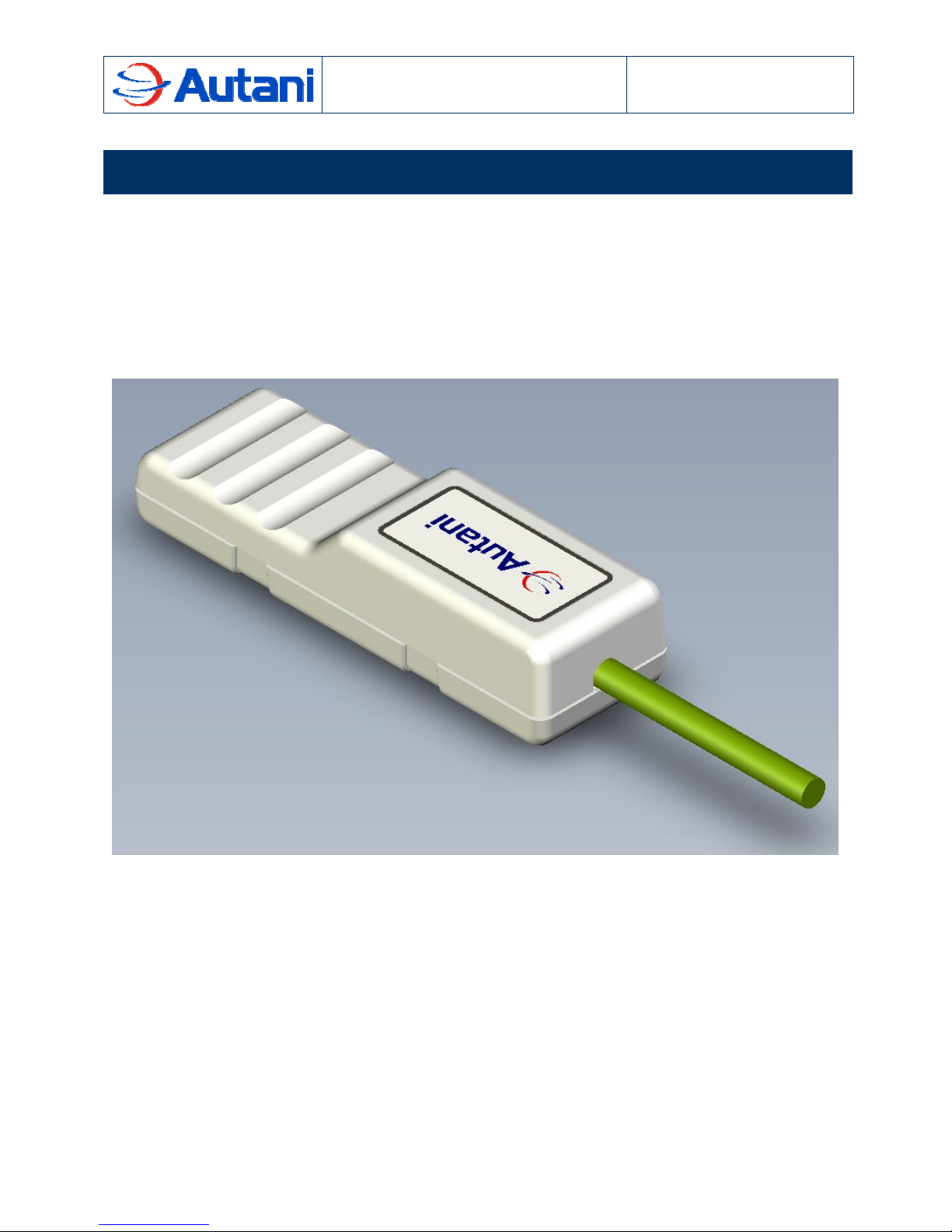
ZigBee to RS485 Bridge (ZRB)
1000127-01
Document Number: 80027
7125 Columbia Gateway Drive, Suite 200
The information contained in this document is proprietary and confidential information of Autani Corporation. Any use of this information
without the expressed written consent of Autani Corporation is prohibited.
Columbia, MD 21046
CONFIDENTIAL AND PROPRIETARY
Page 2

ZigBee to RS485 Bridge (ZRB)
Version Date Changed By Revision Description
1 16-Nov-2009 JAD Initial Release
Users Manual
1. Description
Table of Contents
1. Description...............................................................................................................3
2. Ordering Information...............................................................................................4
3. Specifications...........................................................................................................4
3.1 Absolute Maximum Ratings...........................................................................................................4
3.2 Recommended Operating Conditions...........................................................................................4
3.3 DC Electrical Specifications ..........................................................................................................4
3.4 RF Electrical Characteristics .........................................................................................................5
4. Physical Interface ....................................................................................................5
5. Certifications............................................................................................................6
5.1 FCC – United State .......................................................................................................................6
5.2 IC – Canada ..................................................................................................................................6
6. Theory of Operation.................................................................................................7
The information contained in this document is proprietary and confidential information of Autani Corporation. Any use of this
information without the expressed written consent of Autani Corporation is prohibited.
CONFIDENTIAL AND PROPRIETARY
2 of 7
Page 3
ZigBee to RS485 Bridge (ZRB)
Users Manual
1. Description
1. Description
The ZigBee to RS485 Bridge (ZRB) provides a cost-effective path to wirelessly enable many
devices which still use wired commutations channels. The wireless side of the ZRB employs an
RF transceiver in the 2.4 GHz ISM band based on the IEEE 802.15.4 wireless network protocol.
The wired side of the ZRB communicates in full or half duplex differential modes (i.e. RS485 or
RS422).
Features
FCC (V8NZRB1000127) and IC (7737A-ZRB1000127) certified
Approximately 500 ft LOS transmit/receive distance
The information contained in this document is proprietary and confidential information of Autani Corporation. Any use of this
information without the expressed written consent of Autani Corporation is prohibited.
CONFIDENTIAL AND PROPRIETARY
3 of 7
Page 4

ZigBee to RS485 Bridge (ZRB)
Users Manual
2. Ordering Information
2. Ordering Information
Part Number Ordering Number Description
ZRB1000127 1000127-01 Aprilaire 8870 Thermostat Interface Module
ZRB1000127 1000127-02 Jackson System’s T-32-P Thermostat Interface Module
ZRB1000127 1000127-05 National Meter Interface Module
3. Specifications
3.1 Absolute Maximum Ratings
Note: Exceeding the maximum ratings may cause permanent damage to the unit
Parameter Test Condition Min. Max. Unit
Input Voltage (Vdd) -150 50 V
Voltage on Signal Pin (Rx+, Rx-, Tx+, Tx-) -9 14 V
Storage Temperature -25 80
o
C
3.2 Recommended Operating Conditions
Note: Operating conditions outside those listed here may cause inappropriate and
unpredictable behavior.
Parameter Test Condition Min. Max. Unit
Input Voltage (Vdd) At 25oC 9 40 VDC
Input Voltage (Vdd) At 25oC 9 28 VAC
Operating Temperature 0 60
o
C
3.3 DC Electrical Specifications
Test conditions unless otherwise specified: at 25oC, Vdd = 24VAC, No load on RS485 Bus,
LEDs off.
Parameter Test Condition Typ. Max. Unit
Operational Current
Input Current (Idd) 25 31 mA
The information contained in this document is proprietary and confidential information of Autani Corporation. Any use of this
information without the expressed written consent of Autani Corporation is prohibited.
CONFIDENTIAL AND PROPRIETARY
4 of 7
Page 5

ZigBee to RS485 Bridge (ZRB)
Users Manual
4. Physical Interface
3.4 RF Electrical Characteristics
Parameter Test Condition Min. Typ. Max. Unit
Frequency Range At 25oC 2400 2500 MHz
1% PER, 20byte
Sensitivity
High-side Adjacent Channel Rejection
Low-side Adjacent Channel Rejection
Other Channel Rejection
802.11g Rejection centered at
+12MHz or -13MHz
Maximum Input Signal Strength 0 dBm
Relative Frequency Error -120 120 ppm
packet defined
by IEEE 802.15.4
IEEE 802.15.4
signal at -82 dBm
IEEE 802.15.4
signal at -82 dBm
IEEE 802.15.4
signal at -82 dBm
35 dB
-99 -94 dBm
35 dB
35 dB
40 dB
4. Physical Interface
All signals are from the perspective of the ZRB.
Wire
Number
Color
1 No wire present - Reserved for future feature expansion
2 Red PWR Input power of the ZRB
3 Blue Rx+ Positive half of the Receiver differential pair
4 White Rx- Negative half of the Receiver differential pair
5 Yellow Tx- Negative half of the Transmitter differential pair
6 Green Tx+ Positive half of the Transmitter differential pair
7 Black GND Input ground and RS485 reference of the ZRB
8 No wire present - Reserved for future feature expansion
Signal
Name
Description
The information contained in this document is proprietary and confidential information of Autani Corporation. Any use of this
information without the expressed written consent of Autani Corporation is prohibited.
CONFIDENTIAL AND PROPRIETARY
5 of 7
Page 6

ZigBee to RS485 Bridge (ZRB)
Users Manual
5. Certifications
5. Certifications
5.1 FCC – United State
The ZRB complies with Part 15 of the Federal Communications Commission rules and
regulations. Any modifications to the ZRB may violate the rules of the FCC and make operation
of the module unlawful. FCC ID: V8NZRB1000127.
NOTE 1: This equipment has been tested and found to comply with the limits for a Class B
digital device, pursuant to part 15 of the FCC Rules. These limits are designed to provide
reasonable protection against harmful interference in a residential installation. This equipment
generates, uses, and radiates radio frequency energy and, if not installed and used in
accordance with the instructions, may cause harmful interference to radio communications.
However, there is no guarantee that interference will not occur in a particular installation. If this
equipment does cause harmful interference to radio or television reception, which can be
determined by turning the equipment off and on, the user is encouraged to try to correct the
interference by one or more of the following measures:
Reorient or relocate the receiving antenna.
Increase the separation between the equipment and receiver.
Connect the equipment into an outlet on a circuit different from that to which the
receiver is connected.
Consult the dealer or an experienced radio/ TV technician for help.
NOTE 2: The ZRB complies with the FCC RF radiation exposure limits set forth for an
uncontrolled environment. The ZRB must be installed and/or operated with a minimum distance
of 8 in. (20 cm.) between the antenna and people.
NOTE 3: This device complies with part 15 of the FCC Rules. Operation is subject to the
following two conditions: (1) This device may not cause harmful interference, and (2) this device
must accept any interference received, including interference that may cause undesired
operation
5.2 IC – Canada
The ZRB is IC certified. IC ID: 7737A-ZRB1000127.
The information contained in this document is proprietary and confidential information of Autani Corporation. Any use of this
information without the expressed written consent of Autani Corporation is prohibited.
CONFIDENTIAL AND PROPRIETARY
6 of 7
Page 7

ZigBee to RS485 Bridge (ZRB)
Users Manual
6. Theory of Operation
6. Theory of Operation
The ZRB was designed to be powered from the same voltage that a thermostat or doorbell
system operate from, 24 VAC. However, the ZRB is flexible enough to be powered from other
power sources as well. Refer to the Specifications section for more detailed power
requirements.
The serial communications port on the ZRB is capable of full-duplex and half-duplex operations,
depending on firmware loaded into the ZRB. The ZRB can interface with a host of RS485
based protocols such as LonWorks, BACnet, Modbus and other proprietary protocols based on
the firmware image programmed into the device. Commands and data can originate from either
the wired or wireless sides of the ZRB. When operating as a full-duplex device the Rx and Tx
pairs are connected to the corresponding pair on the communicating device. When operating in
half-duplex mode the positive pair and negative pair are attached together to the corresponding
connection on the communicating device.
The ZRB uses ZigBee in the 2.4 GHz ISM band to communicate wirelessly. There are two
LEDs on the bottom of the ZRB which indicate network status and unit status. The pushbutton
is used to leave and join ZigBee networks. When joined to a ZigBee network with an Energy
Manager the ZRB becomes one part of a multifaceted system designed to eliminate wasted
energy and increase operating efficiency. When paired with another ZRB to replace a wire the
communications channel requires no special personnel for installation thereby saving money
and time.
Full-Duplex
ZRB Device
+
-
-
+
+
-
-
+
Half-Duplex
ZRB Device
+
-
-
+
+
-
GND
The information contained in this document is proprietary and confidential information of Autani Corporation. Any use of this
information without the expressed written consent of Autani Corporation is prohibited.
CONFIDENTIAL AND PROPRIETARY
7 of 7
 Loading...