

Page 1

Users Manual
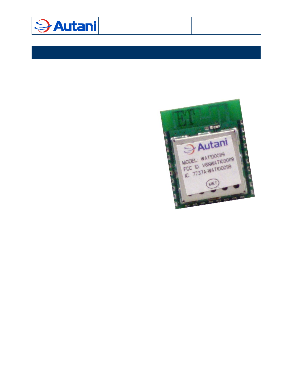
Wireless Autani Transceiver (WAT)
1000119-01
Fully Integrated IEEE 802.15.4 Transceiver Module
Document Number: 80016
7125 Columbia Gateway Drive, Suite 200
Columbia, MD 21046
The information contained in this document is proprietary and confidential information of Autani Corporation. Any use of this information
without the expressed written consent of Autani Corporation is prohibited.
CONFIDENTIAL AND PROPRIETARY
Page 2

Wireless Autani Transceiver (WAT)
Version Date Changed By Revision Description
1 3-Feb-2009 JAD Initial Release
2 10-Feb-2009 JAD Added FCC notes
3 11-Feb-2009 HMM Added Note numbers and -01 to title page
Users Manual
1. Description
Table of Contents
1. Description...............................................................................................................3
2. Ordering Information...............................................................................................4
3. Specifications...........................................................................................................4
3.1 Absolute Maximum Ratings........................................................................................................... 4
3.2 Recommended Operating Conditions ........................................................................................... 4
3.3 Electrical Specifications.................................................................................................................5
4. EM250 Peripherals and Capabilities.......................................................................6
5. Antenna ....................................................................................................................8
6. Dimensions ..............................................................................................................9
6.1 WAT Module..................................................................................................................................9
6.2 Recommended Land Pattern ......................................................................................................10
6.3 Keep-out Area .............................................................................................................................11
7. Certifications..........................................................................................................12
7.1 FCC – United State .....................................................................................................................12
7.2 IC – Canada ................................................................................................................................12
8. Processing .............................................................................................................13
8.1 Reflow Soldering .........................................................................................................................13
8.2 Repeat Reflow Soldering............................................................................................................. 14
8.3 Wave Soldering ...........................................................................................................................14
8.4 Hand Soldering............................................................................................................................14
8.5 Optical Inspection ........................................................................................................................ 14
8.6 Module Rework............................................................................................................................14
8.7 Alterations.................................................................................................................................... 14
9. References .............................................................................................................15
The information contained in this document is proprietary and confidential information of Autani Corporation. Any use of this
information without the expressed written consent of Autani Corporation is prohibited.
CONFIDENTIAL AND PROPRIETARY
2 of 15
Page 3
Wireless Autani Transceiver (WAT)
Users Manual
1. Description
1. Description
The Wireless Autani Transceiver (WAT) provides a cost-effective RF transceiver for 2.4 GHz
IEEE 802.15.4 wireless networks. The WAT is based on the Ember EM250 System-on-a-chip
(SoC) and it has been designed to support larger, denser, sleepier, more mobile, secure, and
resilient wireless networks.
Features
Design for EmberZNet networks
Miniature footprint: 1.000” x 0.800”
Integrated PCB antenna
16 RF channels
Integrated hardware support for Ember development environment
Non-intrusive debug port (SIF)
AES 128-bit encryption
Low power consumption
Constant RF output power over 2.1V - 3.6V voltage range
FCC (V8NWAT1000119) and IC (7737A-WAT1000119) certified
128kB Flash Memory
5kB SRAM
16-bit XAP2b microprocessor
16 general purpose inputs and outputs (GPIO)
UART, SPI, and I2C interfaces
Integrated ADC with 12-bit maximum resolution
The information contained in this document is proprietary and confidential information of Autani Corporation. Any use of this
information without the expressed written consent of Autani Corporation is prohibited.
CONFIDENTIAL AND PROPRIETARY
3 of 15
Page 4

Wireless Autani Transceiver (WAT)
Users Manual
2. Ordering Information
Part Number Ordering Number Description
2. Ordering Information
WAT1000119
1000119-100 Wireless Autani Transceiver
IEEE 802.15.4 Module
3. Specifications
3.1 Absolute Maximum Ratings
Note: Exceeding the maximum ratings may cause permanent damage to the module
Parameter Value Unit
Power Supply Voltage (VDD) 3.6 V
Voltage on any digital pin VDD+0.3,
Max 3.6
Storage Temperature Range -40 to 125
DC
V
DC
o
C
3.2 Recommended Operating Conditions
Note: Operating conditions outside those listed here may cause inappropriate behavior.
Parameter Min Typ Max Unit
Power Supply Voltage (VDD) 2.1 3.6 V
Ambient Temperature Range -40 25 85
Logic Input Low Voltage 0 20% V
Logic Input High Voltage 80% V
DD
V
DD
DD
The information contained in this document is proprietary and confidential information of Autani Corporation. Any use of this
information without the expressed written consent of Autani Corporation is prohibited.
CONFIDENTIAL AND PROPRIETARY
4 of 15
o
DC
C
V
V
Page 5
Wireless Autani Transceiver (WAT)
Users Manual
3. Specifications
3.3 Electrical Specifications
Parameter Min Typ Max Unit
General Characteristics
RF Frequency Range 2.400 2.4835 GHz
Data Rate 250 Kbps
Processor core frequency 12 MHz
Flash Memory 128 kB
SRAM 5 kB
Power Consumption
Transmit Mode 35.5 mA
Receive Mode 35.5 mA
Processor Only Mode 8.5 mA
Sleep Mode 1 uA
Logic Characteristics
Logic Input High 80% V
DD
V
Logic Input Low 0 20% V
Logic Output High 82% V
DD
V
Logic Output Low 0 18% V
Output Source Current 4 mA
Output Sink Current 4 mA
Logic High Input Current 0.5 uA
Logic Low Input Current -0.5 uA
Input Pull-up Resistance 30 kΩ
Input Pull-down Resistance 30 kΩ
DD
DD
DD
DD
V
V
V
V
The information contained in this document is proprietary and confidential information of Autani Corporation. Any use of this
information without the expressed written consent of Autani Corporation is prohibited.
CONFIDENTIAL AND PROPRIETARY
5 of 15
Page 6

Wireless Autani Transceiver (WAT)
Users Manual
4. EM250 Peripherals and
Capabilities
4. EM250 Peripherals and Capabilities
The WAT Module provides 16 GPIO ports that are shared with alternate functions within the
EM250 SoC. The alternate functions can be used on a variety of different GPIO. All GPIOs are
configurable as input, output, or bi-directional and have an internal pull-up or pull-down.
The WAT Module offers two serial controllers, a multi-channel 12-bit Analog-to-Digital converter
(ADC), and two16-bit timers. Serial Controller SC1 can be configured for SPI (master only), I2C
(master only), or UART. Serial Controller CS2 can be configured for SPI (master or slave) or
I2C (master). The ADC can be configured to provide anywhere from 5 to 12 bits of precision on
4 single-ended channels or 2 differential channels in addition to monitoring the supply voltage.
The 16-bit timers have configurable clock sources, a loadable start point, two output compare
registers, two input capture registers, and can be configured to operate up/down counting,
single shot counting, and pulse width modulation (PWM).
The WAT Module provides access to the SIF module programming and debugging interface.
Please consult the EM250 datasheet for detailed information about using the peripherals.
WAT Module Pin Assignment
Pin # Name Type Description
1 Ground GND Ground
2 Ground GND Ground
3 Ground GND Ground
4 V
DD
V
DD
Power Supply Input
5 RSTB DI Processor Reset, active low
6 GPIO11 DI/DO GPIO, SC1-CTS, SC1-SPI_CLK, Capture Input A of TMR2
7 GPIO12 DI/DO GPIO, SC1-RTS, Capture Input B of TMR2
8 GPIO0 DI/DO GPIO, SC2-SPI_MOSI, Capture Input A of TMR1
9 GPIO1 DI/DO GPIO, SC2-SPI_MISO, SC2-I2C_DATA, Capture Input A of
TMR2
10 GPIO2 DI/DO GPIO, SC2-SPI_CLK, SC2-I2C_CLK, Capture Input B of
TMR2
11 GPIO3 DI/DO GPIO, SC2-SPI_SS, Capture Input B of TMR1
12 GPIO4 DI/DO/AI GPIO, ADC0, PTI_EN
13 GPIO5 DI/DO/AI GPIO, ADC1, PTI_DATA
14 GPIO6 DI/DO/AI GPIO, ADC2, External Input of TMR2, External Enable of
TMR1
15 GPIO7 DI/DO/AI GPIO, ADC3GPIO8
The information contained in this document is proprietary and confidential information of Autani Corporation. Any use of this
information without the expressed written consent of Autani Corporation is prohibited.
CONFIDENTIAL AND PROPRIETARY
6 of 15
Page 7

Wireless Autani Transceiver (WAT)
Users Manual
4. EM250 Peripherals and
Capabilities
16 GPIO8 DI/DO/AO GPIO, ADC Reference Output, External Input of TMR1,
External Enable of TMR2, IRQA
17 GPIO9 DI/DO GPIO, SC1-Tx, SC1-SPI_MOSI, SC1-I2C_DATA, Capture
Input A of TMR1
18 GPIO10 DI/DO GPIO, SC1-Rx, SC1-SPI_MISO, SC1-I2C_CLK, Capture
input B of TMR1
19 SIF_CLK DI SIF Programming Interface Clock
20 SIF_MISO DO SIF Programming Interface Data Output
21 SIF_MOSI DI SIF Programming Interface Data Input
22 LOADB DI/DO SIF Programming Interface Load Strobe
23 GPIO16 DI/DO GPIO, TMR1 Output B, Capture Input B of TMR2, IRQD
24 GPIO15 DI/DO GPIO, TMR1 Output A, Capture Input A of TMR1, IRQC
25 GPIO14 DI/DO GPIO, TMR2 Output B, Capture Input B of TMR1, IRQB
26 GPIO13 DI/DO GPIO, TMR2 Output A, Capture Input A of TMR1
27 Ground GND Ground
28 Ground GND Ground
Unused GPIO should be left unconnected. The EM250 should be configured to hold
unconnected GPIO in a known state.
DI = Digital Input
DO = Digital Output
AI = Analog Input
AO = Analog Output
= Power Input
V
DD
GND = Ground
The information contained in this document is proprietary and confidential information of Autani Corporation. Any use of this
information without the expressed written consent of Autani Corporation is prohibited.
CONFIDENTIAL AND PROPRIETARY
7 of 15
Page 8

Wireless Autani Transceiver (WAT)
Users Manual
5. Antenna
5. Antenna
WAT Module includes an integrated PCB trace antenna. The PCB antenna employs a
meandering F-antenna design that is very compact and supports omni-directional signal
radiation. To maximize the antenna efficiency an adequate ground should be provided on the
base board. The position of the module on the base board and overall design of the product
enclosure contributes to the antenna’s performance.
Here are some guidelines to help ensure antenna performance:
Keep all copper (planes and traces) away form the antenna portion of the module
Keep the antenna away from metal parts (i.e. enclosures, large heat sinks, etc…)
Keep internal wiring and other components away from the Antenna
Do not place the antenna inside a metal enclosure
Keep plastic enclosures ½ in. or more from the antenna
The information contained in this document is proprietary and confidential information of Autani Corporation. Any use of this
information without the expressed written consent of Autani Corporation is prohibited.
CONFIDENTIAL AND PROPRIETARY
8 of 15
Page 9

Wireless Autani Transceiver (WAT)
6. Dimensions
6.1 WAT Module
Users Manual
6. Dimensions
CONFIDENTIAL AND PROPRIETARY
The information contained in this document is proprietary and confidential information of Autani Corporation. Any use of this
information without the expressed written consent of Autani Corporation is prohibited.
9 of 15
Page 10

Wireless Autani Transceiver (WAT)
Users Manual
6.2 Recommended Land Pattern
6. Dimensions
CONFIDENTIAL AND PROPRIETARY
The information contained in this document is proprietary and confidential information of Autani Corporation. Any use of this
information without the expressed written consent of Autani Corporation is prohibited.
10 of 15
Page 11

Wireless Autani Transceiver (WAT)
6.3 Keep-out Area
Users Manual
6. Dimensions
For maximum antenna performance hang the antenna keep-out area over the edge of the base
board. Placing a ground plane on the layer directly beneath the WAT Module will allow you to
run traces under this area. The WAT board can be placed on a base board without antenna
overhang as long as all copper is kept away from the antenna keep-out area.
CONFIDENTIAL AND PROPRIETARY
The information contained in this document is proprietary and confidential information of Autani Corporation. Any use of this
information without the expressed written consent of Autani Corporation is prohibited.
11 of 15
Page 12

Wireless Autani Transceiver (WAT)
Users Manual
7. Certifications
7. Certifications
7.1 FCC – United State
The WAT Module complies with Part 15 of the Federal Communications Commission rules and
regulations. To continue compliance with Part 15 the end user MUST include a visible label on
the outside of the final product which indicates the internal radio module is FCC approved. The
exterior label can use wording such as: “Contains FCC ID: V8NWAT1000119”. To meet the
section 15.209 emissions requirements in the restricted bands of section 12.205, the transceiver
transmitter power for the EM250 can be set no higher than +3.0 dBm for all channels. Any
modifications to the WAT Module may violate the rules of the FCC and make operation of the
module unlawful. The user is responsible for obtaining compliance for unintentional radiators on
the final product.
NOTE 1: This equipment has been tested and found to comply with the limits for a Class B
digital device, pursuant to part 15 of the FCC Rules. These limits are designed to provide
reasonable protection against harmful interference in a residential installation. This equipment
generates, uses, and radiates radio frequency energy and, if not installed and used in
accordance with the instructions, may cause harmful interference to radio communications.
However, there is no guarantee that interference will not occur in a particular installation. If this
equipment does cause harmful interference to radio or television reception, which can be
determined by turning the equipment off and on, the user is encouraged to try to correct the
interference by one or more of the following measures:
Reorient or relocate the receiving antenna.
Increase the separation between the equipment and receiver.
Connect the equipment into an outlet on a circuit different from that to which the
receiver is connected.
Consult the dealer or an experienced radio/ TV technician for help.
NOTE 2: The WAT Module complies with the FCC RF radiation exposure limits set forth for an
uncontrolled environment. The WAT Module must be installed and/or operated with a minimum
distance of 8 in. (20 cm.) between the antenna and people.
NOTE 3: This device complies with part 15 of the FCC Rules. Operation is subject to the
following two conditions: (1) This device may not cause harmful interference, and (2) this device
must accept any interference received, including interference that may cause undesired
operation
7.2 IC – Canada
The WAT Module is IC certified. The labeling requirements for Industry Canada are similar to
those of the FCC. A visible label must be placed on the outside of the final product clearing
indicating the IC Labeling of the internal WAT Module. The user is responsible for the end
product complying with ICES-003 (Unintentional Radiators).
The information contained in this document is proprietary and confidential information of Autani Corporation. Any use of this
information without the expressed written consent of Autani Corporation is prohibited.
CONFIDENTIAL AND PROPRIETARY
12 of 15
Page 13

Wireless Autani Transceiver (WAT)
Users Manual
8. Processing
8. Processing
!!WARNING!! The WAT Module contains extremely sensitive electronic circuitry. Handle board
with proper ESD protocol at all times.
8.1 Reflow Soldering
A convection soldering oven is recommended. Preheat the assembly at a rate of 3oC/sec and
stop at a final temperature of 150-200
20-40 seconds, do not exceed 260
o
C/sec. Use of “no clean” solder is highly recommended as all cleaning methods carry some
6
o
C. Limit time above solder paste liquid temperatures to
o
C. Allow the assembly to cool at a rate no greater than
risk of damaging the module and its markings.
The information contained in this document is proprietary and confidential information of Autani Corporation. Any use of this
information without the expressed written consent of Autani Corporation is prohibited.
CONFIDENTIAL AND PROPRIETARY
13 of 15
Page 14

Wireless Autani Transceiver (WAT)
Users Manual
8. Processing
8.2 Repeat Reflow Soldering
Repeated reflow after the WAT Module has been populated is discouraged.
8.3 Wave Soldering
If wave soldering is required on the base board due to the use of leaded components, it is
recommended that only a single pass is used.
8.4 Hand Soldering
Hand soldering is possible but should be done with care to avoid excessive heat application to
the WAT Module.
8.5 Optical Inspection
After soldering the WAT Module to the base board, an optical inspection is recommended to
check for the following:
Accurate alignment and centering of the module over the pads.
Appropriate solder joints.
Unintended solder bridges.
8.6 Module Rework
The WAT Module can be unsoldered from the base board. Take care not to overheat the
module. Never attempt to rework the module itself, any such attempts will invalidate any
manufactures warranty and potentially cause the module to violate FCC and IC specifications.
8.7 Alterations
Any and all alterations to the WAT Module are highly discouraged and are completed at the
consumer’s risk. Such actions will invalidate any manufactures warranty and potentially cause
the module to violate FCC and IC specifications.
The information contained in this document is proprietary and confidential information of Autani Corporation. Any use of this
information without the expressed written consent of Autani Corporation is prohibited.
CONFIDENTIAL AND PROPRIETARY
14 of 15
Page 15

Wireless Autani Transceiver (WAT)
Users Manual
9. References
9. References
[1]. EM250 Datasheet (http://www.ember.com/pdf/120-0082-000_EM250_Datasheet.pdf)
[2]. FCC Part 15 (http://www.fcc.gov/oet/info/rules/part15/PART15_07-10-08.pdf
)
The information contained in this document is proprietary and confidential information of Autani Corporation. Any use of this
information without the expressed written consent of Autani Corporation is prohibited.
CONFIDENTIAL AND PROPRIETARY
15 of 15
 Loading...