

Page 1
Overview
The Switched Light Controller (SLC) along with the Autani
Energy Manager provides a complete, expandable Energy
Efficiency System for the commercial building industry. The
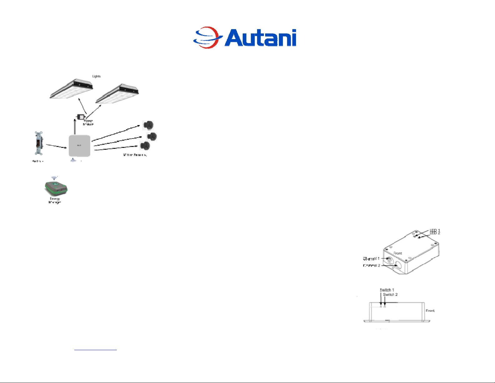
SLC system consists of the SLC, wall switch(s), Power Pack
and motion sensor(s). A functional diagram is shown below.
Switched Lighting Control Module
Specifications
Power:
SLC: 24VDC
Power Pack: 120/277VAC Input, 24V DC o ut p ut , 20Amp
switching load capability
Operating Temperature:
Nominal ambient temperature of 25 degrees Celsius
Wireless Communications:
2.4 GHz, 16 channel spread spectrum
Operating Temperature:
The rated loads are in accordance to an ambient temperature of
25 degrees Celsius
One SLC can control one or two independent switch circuits,
of any type: single, two way, three way or four way. Multiple
motion sensors can be wire-OR together to enhance coverage,
all from a single channel on the SLC. Different sensor
profiles are available, from wide angle to narrow sensitive
motion detection. The switch(s), motion sensor(s) and
control signals to the Power Pack are all low voltage.
Autani Corporation
7125 Columbia Gateway Drive
Suite 200
This device complies with Part 15 of FCC rules. Operation is subject to the
following two conditions: 1) this device may not cause harmful interference
and, 2) this device must accept any interference received, including
interference that may cause undesired operation.
Changes of modifications not expressly approved by the party responsible for
compliance could void the user’s authority to operate the equipment.
This Class B digital apparatus complies with Canadian ICES-003.
UC:7737A-SLC1000105
FCC ID:V8NSLC1000105
This device is not UL Listed.
Product code: 1000105
Columbia, MD 21046
Phone: 443-320-2233
Web: www.autani.com
Email: info@autani.com
Document No. 80006.2 Copyright 2008, Autani Corporation. All rights reserved.
Technical Support
If you have questions about the installation or operation of this
device, call Autani technical support at: 443-320-2233
Warning! There are no serviceable parts within the SLC and no
attempt should be made to disassemble the device.
Warning! Improper connection of the device may result in
permanent damage to the device. Follow installation
instructions carefully.
Caution! Using this product in any manner other than outlined
in this document is not supported and voids any warranty.
Autani is not responsible for any damages or injuries incurred
as a result of misuse or abuse of this product.
Device Installation
The branch circuit should be turned off before any installation is
started. If this is an upgrade the existing wiring can be utilized
as needed as long as all codes are followed. The SLC can be
mounted on an interior wall or above the ceiling as long as it is
accessible if needed. Wiring to and from the SLC is all low
voltage. Follow the manufactures directions for installing the
Power Pack. It is recommended that a licensed electrician install
the Power Pack. The motion sensors are designed to be mounted
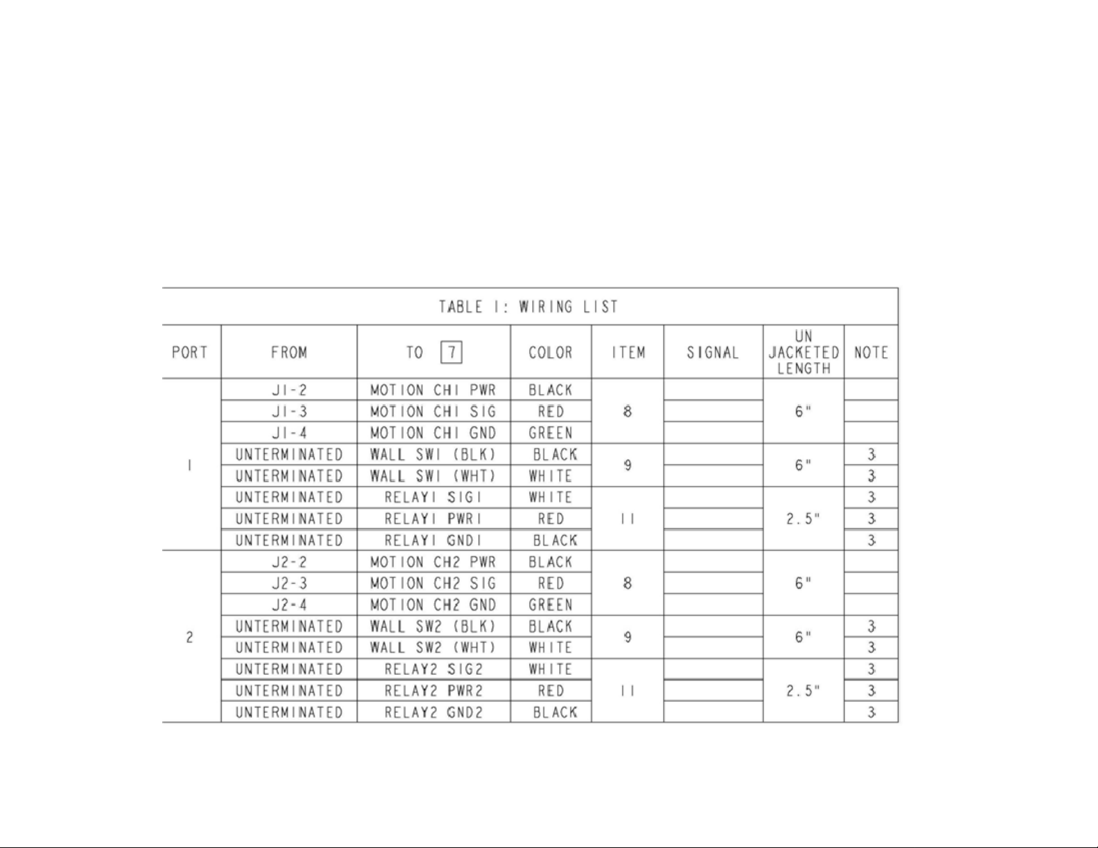
on the typical one inch wide channel for drop ceilings. The RJ11 connector on the motion sensor plugs into the female socket
on the cable run from the SLC. See the wiring table below for
connecting the SLC to the other components as required.
SLC identification:
Page 2
LED 1 - Blinks amber when either or both of the power
packs are powered on.
LED 2 – Blinks green when the node is properly
communicating with the network. In this mode, the
LED may occasionally flash red. This is normal and is
an indication of wireless network activity. These
flashes of red will be brief and the predominant color
will be flashing green.
If this LED is blinking red, the node is attempting to
locate a wireless network to join.
Switch 1 – Causes the node to leave the network and begin to
look for a commissioning node to join. In this case, LED2
begins to blink red. To activate this mode, the button should be
depressed until LED2 begins to blink red. This may require the
button to be held down for a few seconds.
Switch 2 - a short press of this switch will toggle the state of
both output channels. LED1 will begin to blink amber when
the output channels are powered on. This functionality is
present even if this device is not yet part of a wireless network.
Once the SLC is installed and power restored to the
branch circuit refer to the Autani E2/E4 System Users
Guide for further instructions on utilizing the device via
the wireless interface.
Document No. 80006.2 Copyright 2008, Autani Corporation. All rights reserved.
 Loading...