

Page 1
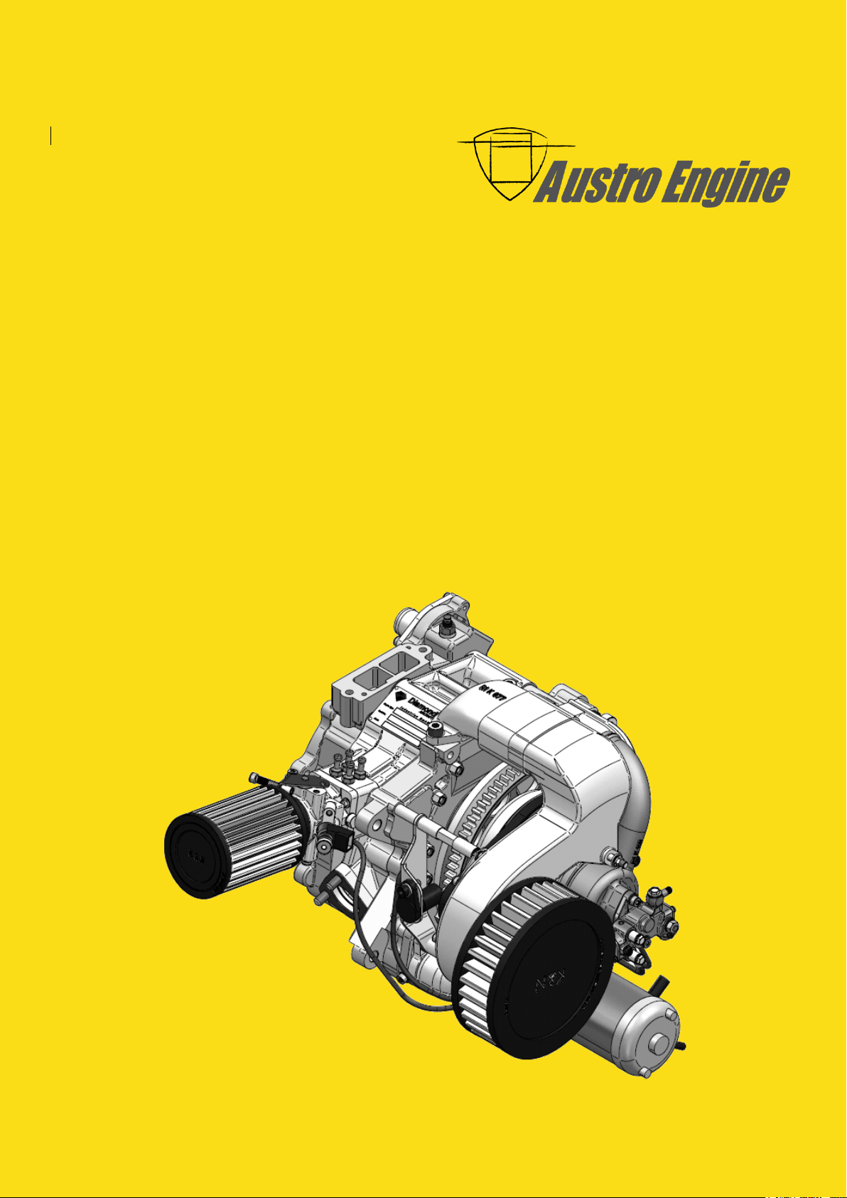
ENGINE MANUAL
IAE50R – AA
E1.01.05 – E
Issue date: 05.Dec.2014
Page: Intro - 1
Revision No: 8
Engine Manual
Operation / Maintenance / Installation
IAE50R – AA
Doc. No.: E1.01.05 – E
Page 2

ENGINE MANUAL
IAE50R – AA
E1.01.05 – E
Issue date: 25.Jan.2018
Page: Coversheet - 1
Revision no: 9
Page 3
ENGINE MANUAL
IAE50R – AA
E1.01.05 – E
Issue date: 25.Jan.2018
Page: Coversheet - 2
Revision no: 9
Date: Wiener Neustadt, 25-Jan-2018
Author: Austro Engine GmbH
Rudolf – Diesel – Straße - 11
2700 Wiener Neustadt, Austria
Document number: E1.01.05 – E
Revision: 9
Page 4
ENGINE MANUAL
IAE50R – AA
E1.01.05 – E
Issue date: 25.Jan.2018
Page: 0-1
Revision no: 9
0 TABLE OF CONTENTS
0 TABLE OF CONTENTS ..................................................................................................................... 0-1
1 INTRODUCTION .............................................................................................................................. 0-1
1.1 Record of Revisions .......................................................................................................................... 1-2
1.2 List of Revisions ................................................................................................................................ 1-3
1.3 List of Valid Pages ............................................................................................................................ 1-5
1.4 List of Incorporated Temporary Revisions .................................................................................... 1-7
2 GENERAL INFORMATION .............................................................................................................. 2-1
3 SAFETY INFORMATION ................................................................................................................. 3-1
3.1 Safety Symbols ................................................................................................................................. 3-1
3.2 Model Designation Breakdown ....................................................................................................... 3-2
3.3 Replacement parts ........................................................................................................................... 3-2
4 RESERVED ......................................................................................................................................... 4-1
5 GENERAL ENGINE DATA ................................................................................................................ 5-1
5.1 Description ........................................................................................................................................ 5-1
5.2 Technical data ................................................................................................................................... 5-1
5.2.1 Design Responsibility
5.2.2 Certification
................................................................................................................................... 5-1
5.2.3 Engine Overall Dimensions
5.2.4 Engine Particulars
5.2.5 Out – put Drive
5.2.6 Net Dry Weight
5.2.7 Cooling
........................................................................................................................................... 5-4
5.2.8 Fuel Specification
5.2.9 Fuel Consumption Curve
5.2.10 Pressure to Fuel Injector
5.2.11 Lubrication
.................................................................................................................................... 5-5
5.2.12 Oil Specification
................................................................................................................... 5-1
......................................................................................................... 5-2
........................................................................................................................ 5-3
............................................................................................................................. 5-3
............................................................................................................................. 5-3
......................................................................................................................... 5-4
............................................................................................................. 5-4
............................................................................................................ 5-5
............................................................................................................................ 5-5
6 OPERATING DATA / LIMITATIONS ............................................................................................ 6-1
6.1 Maximum Take – off Rating ............................................................................................................ 6-1
6.2 Maximum Continuous Rating .......................................................................................................... 6-1
6.2.1 Power Curve
6.3 Operating Limitations....................................................................................................................... 6-2
6.3.1 Engine RPM
6.3.2 Ambient Temperature Limits
6.3.3 Liquid Coolant Temperature Limits
6.3.4 Rotor Cooling Air Outlet Temperature Limits
6.3.5 Exhaust Gas Temperature (EGT)
6.3.6 Fuel Pressure
6.3.7 Altitude
6.4 Manuals .............................................................................................................................................. 6-3
7 COMPONENTS .................................................................................................................................. 7-1
7.1 Description of Components ............................................................................................................. 7-2
7.1.1 Rear Assemblies
7.1.2 Front Assemblies
7.1.3 Centre and Rotating Assembly
7.1.4 Rotor Sealing
................................................................................................................................. 6-2
................................................................................................................................... 6-2
...................................................................................................... 6-2
........................................................................................... 6-3
........................................................................... 6-3
............................................................................................... 6-3
................................................................................................................................ 6-3
.......................................................................................................................................... 6-3
........................................................................................................................... 7-2
.......................................................................................................................... 7-2
................................................................................................... 7-2
................................................................................................................................ 7-2
Page 5
ENGINE MANUAL
IAE50R – AA
E1.01.05 – E
Issue date: 25.Jan.2018
Page: 0-2
Revision no: 9
8 DESCRIPTIONS OF SYSTEMS ....................................................................................................... 8-1
8.1 Fuel System ....................................................................................................................................... 8-1
8.1.1 Typical Schematic Fuel System (provided by engine installer)
8.1.2 Throttle Valve Setting
8.2 Cooling System ................................................................................................................................. 8-2
8.2.1 Liquid Cooling System
8.2.2 Water Pump
.................................................................................................................................. 8-2
8.2.3 Temperature Regulation
8.2.4 Coolant
.......................................................................................................................................... 8-3
8.2.5 System Pressure
8.2.6 Air cooling system
8.2.7 Rotor Cooling Air Parts
9 OPERATING THE ENGINE ............................................................................................................. 9-1
9.1 Starting Procedure and Warm–up ................................................................................................. 9-1
9.2 Engine Start down to approximately -10 °C ................................................................................. 9-2
9.3 Ground Tests..................................................................................................................................... 9-2
9.3.1 Full Power Check
9.3.2 Idle Check
..................................................................................................................................... 9-3
9.3.3 Stopping the Engine
9.4 Power Loss at Altitude ..................................................................................................................... 9-3
9.5 Storage .............................................................................................................................................. 9-4
9.5.1 Storage up to 90 Days
9.5.2 Storage beyond 90 Days
9.5.3 Returning to Service from Storage
.................................................................................................................. 8-1
................................................................................................................. 8-2
............................................................................................................. 8-2
........................................................................................................................... 8-3
........................................................................................................................ 8-3
................................................................................................................ 8-4
.......................................................................................................................... 9-2
.................................................................................................................... 9-3
................................................................................................................ 9-4
............................................................................................................. 9-4
............................................................................................ 9-5
............................................. 8-1
10 ENGINE EMERGENCY PROCEDURES ........................................................................................ 10-1
10.1 Fan Belt Failure ............................................................................................................................... 10-1
10.1.1 Low Oil in the Tank
10.1.2 Low Fuel Pressure
10.1.3 Rotor Cooling Air Temperature
10.1.4 Coolant Temperature
11 MAINTENANCE NOTES ................................................................................................................. 11-1
11.1 Austro Engine GmbH Available Consumables ............................................................................ 11-1
11.2 General Torque Settings................................................................................................................ 11-1
11.2.1 Specific Torque Settings
11.2.2 MAP Hoses
.................................................................................................................................. 11-2
11.2.3 Checking & Setting Fan Belt Tension
11.2.4 Adjusting engine idle speed
12 SCHEDULED MAINTENANCE ...................................................................................................... 12-1
12.1 Maintenance Schedule ................................................................................................................... 12-1
12.2 Typical 50 Hours Check ................................................................................................................. 12-2
12.3 Mandatory Life Limitation.............................................................................................................. 12-3
13 COOLING SYSTEM ......................................................................................................................... 13-4
13.1 Liquid Cooling System ................................................................................................................... 13-4
13.2 Coolant leak check ......................................................................................................................... 13-4
13.3 Coolant System Filling and Bleeding ........................................................................................... 13-4
13.4 Coolant System Pressure Test ...................................................................................................... 13-5
13.5 Air Cooling System ......................................................................................................................... 13-6
13.5.1 Fan Belt
....................................................................................................................................... 13-6
13.5.2 Fan Belt Replacement
.................................................................................................................... 10-1
...................................................................................................................... 10-1
................................................................................................ 10-1
................................................................................................................. 10-1
........................................................................................................... 11-1
...................................................................................... 11-2
..................................................................................................... 11-2
............................................................................................................... 13-6
Page 6
ENGINE MANUAL
IAE50R – AA
E1.01.05 – E
Issue date: 25.Jan.2018
Page: 0-3
Revision no: 9
13.5.3 Air Filters
13.5.4 Air Filter Cleaning Procedure
13.5.5 Rotor Cooling Air Fan Impeller
14 ENGINE INTERNAL INSPECTION .............................................................................................. 14-1
14.1 Spark Plug ....................................................................................................................................... 14-1
15 GROUND RUN ................................................................................................................................. 15-1
15.1 Pre–start Checks Outside Aircraft ................................................................................................ 15-1
15.2 Pre–start Checks Inside Aircraft ................................................................................................... 15-1
15.3 Ground Run ..................................................................................................................................... 15-1
15.4 Ground Run Check List (example) ............................................................................................... 15-2
16 MAINTENANCE AND OVERHAUL ............................................................................................... 16-1
17 TROUBLE SHOOTING ................................................................................................................... 17-1
17.1 General ............................................................................................................................................ 17-1
17.2 Rough Idle ....................................................................................................................................... 17-1
17.3 Engine Misfires on One Spark Plug .............................................................................................. 17-2
17.4 Engine Cannot Develop Full Power .............................................................................................. 17-2
17.5 Excessive Rotor Cooling Outlet Temperatures ........................................................................... 17-2
17.6 Liquid Coolant Overheats on Medium and High Power ............................................................ 17-2
17.7 ECU Error Warning Light Flashes ................................................................................................. 17-3
..................................................................................................................................... 13-7
.................................................................................................... 13-7
................................................................................................. 13-8
18 NOTES FOR INSTALLERS OF ENGINES .................................................................................... 18-1
18.1 General Notes ................................................................................................................................. 18-1
18.2 Notes for engine installers ............................................................................................................ 18-1
18.3 Fuel System ..................................................................................................................................... 18-2
18.3.1 Fuel Specification
18.3.2 Fuel delivery
18.3.3 Fuel filters
................................................................................................................................... 18-3
18.3.4 Pressure Regulator
18.3.5 Water in Fuel
18.3.6 Fuel Lines
18.4 Oil System ....................................................................................................................................... 18-3
18.5 Engine mounting ............................................................................................................................ 18-4
18.6 Exhaust system ............................................................................................................................... 18-4
18.7 Air Filters ......................................................................................................................................... 18-4
18.8 Drive interface ................................................................................................................................ 18-4
19 ELECTRICAL SYSTEM ................................................................................................................... 19-1
19.1 Engine Control System .................................................................................................................. 19-2
.................................................................................................................................... 18-3
19.1.1 Fuel injection
19.1.1.1 Injection Timing ................................................................................................................................ 19-2
19.1.1.2 Load Demand..................................................................................................................................... 19-2
19.1.2 Ignition System
19.1.2.1 Ignition Triggering ............................................................................................................................ 19-2
19.1.2.2 Ignition ............................................................................................................................................... 19-2
19.1.3 Mechanical installation of the ECU
19.1.4 Electrical installation of the ECU
19.1.4.1 Harness Connector for ECU ............................................................................................................. 19-5
19.1.4.2 ECU Pin Assignment .......................................................................................................................... 19-6
19.1.4.3 CAN Bus .............................................................................................................................................. 19-8
19.1.4.4 Option: Installation of ECU according D0160 section 16 CAT Z ................................................. 19-9
19.1.4.5 Error Codes ...................................................................................................................................... 19-10
19.1.4.6 Error Code Table ............................................................................................................................. 19-11
....................................................................................................................... 18-2
............................................................................................................................... 18-2
.................................................................................................................... 18-3
.............................................................................................................................. 18-3
.............................................................................................................................. 19-2
.......................................................................................................................... 19-2
.......................................................................................... 19-3
.............................................................................................. 19-4
Page 7
ENGINE MANUAL
IAE50R – AA
E1.01.05 – E
Issue date: 25.Jan.2018
Page: 0-4
Revision no: 9
19.2 GND Concept IAE50R .................................................................................................................. 19-12
19.3 Sensors and actuators ................................................................................................................. 19-13
19.3.1 Air Temperature sensor
19.3.2 Rotor cooling air out temperature sensor
19.3.3 Map Sensors
19.3.4 Speed Sensors
19.3.5 Ignition Coils
19.3.5.1 H.T. Leads ........................................................................................................................................ 19-19
19.3.5.2 Spark plugs ...................................................................................................................................... 19-19
19.3.6 Injector
............................................................................................................................. 19-16
.......................................................................................................................... 19-17
............................................................................................................................. 19-18
...................................................................................................................................... 19-20
19.3.7 Coolant Temperature Sensor for instruments
19.4 Generator regulator and Generator wiring ............................................................................... 19-22
19.4.1 Mechanical installation of the Generator Regulator
19.4.2 Electrical installation of the Regulator
19.5 Starter ............................................................................................................................................ 19-24
19.5.1 Mechanical installation
19.5.2 Electrical connection of starter
19.6 Electronic Components Capability .............................................................................................. 19-25
19.6.1 Electrical tests
........................................................................................................................... 19-25
19.6.2 Environmental tests
19.6.3 Control System Reliability
19.6.3.1 Control system reliability objective. .............................................................................................. 19-27
19.6.3.2 Software Quality level ..................................................................................................................... 19-27
.......................................................................................................... 19-13
............................................................................ 19-14
...................................................................... 19-21
............................................................ 19-22
.................................................................................. 19-23
............................................................................................................ 19-24
.............................................................................................. 19-24
................................................................................................................. 19-26
....................................................................................................... 19-27
Page 8
ENGINE MANUAL
IAE50R – AA
E1.01.05 – E
Issue date: 25.Jan.2018
Page: 1-1
Revision no: 9
These technical data and the information contained therein are the property of Austro
Engine GmbH and may not be reproduced either in full or in part or passed on to a third
party without written consent from Austro Engine GmbH.
This text must be included in any full or partial reproduction of this documentation.
Copyright © Austro Engine GmbH
1 INTRODUCTION
This engine may only be operated in accordance with the procedures and operating limitations
of the Engine described in this manual.
Page 9
ENGINE MANUAL
IAE50R – AA
E1.01.05 – E
Issue date: 25.Jan.2018
Page: 1-2
Revision no: 9
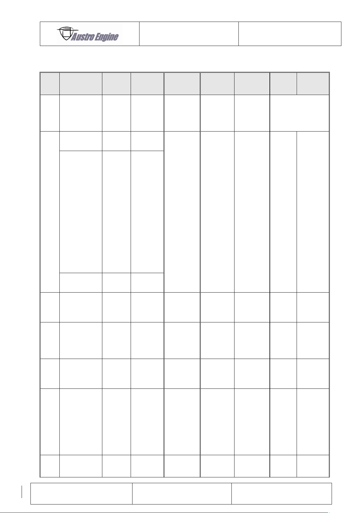
1.1 Record of Revisions
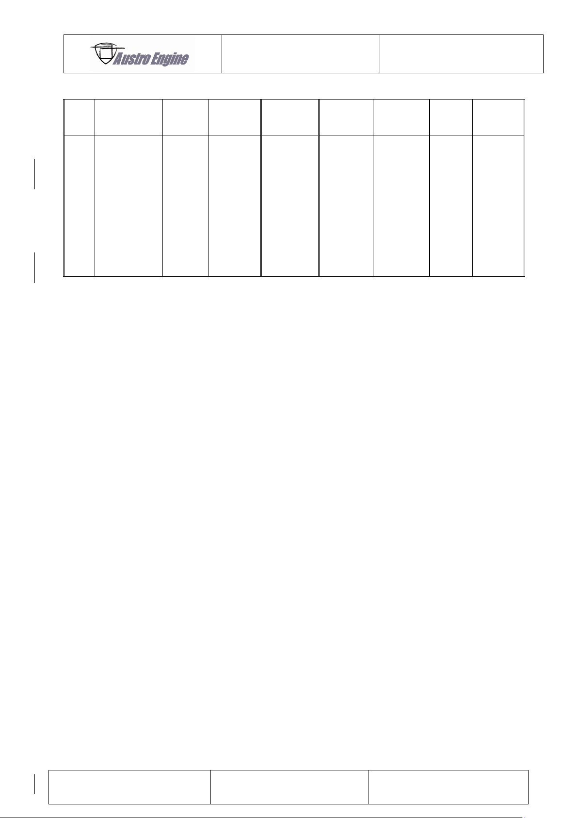
All revisions of this manual must be recorded in chapter 1.2. Revisions of chapter
“6 OPERATING DATA / LIMITATIONS” requires approval by EASA.
All incorporated Temporary Revisions must be recorded in chapter 1.4.
The new or amended text is indicated by a vertical line at the left hand side of the revised
page, with the revision number and data appearing at the bottom of the page.
If pages are revised which contain information valid for your particular serial number
(modification level of the engine, Equipment Inventory, etc.), then this information must be
transferred to the new pages in hand–writing.
Temporary revisions, if applicable, are inserted behind the cover page of this manual.
Temporary revisions are used to provide information on systems or equipment until the next
‘permanent’ revision of the Engine Manual. When a ‘permanent’ revision covers a Mandatory
or Optional Design Change (MDC or ODC), then the corresponding temporary revision is
superseded.
It is the responsibility of the operator to ensure that this manual is maintained to a current
status.
If the address or the ownership of the engine/aircraft changes, an address card has to be sent
to Austro Engine GmbH.
Page 10
ENGINE MANUAL
IAE50R – AA
E1.01.05 – E
Issue date: 25.Jan.2018
Page: 1-3
Revision no: 9
Rev.
No.
Reason
Chapter
Page(s)
Date of
Revision
Approval
Date of
Approval
Date
Inserted
Signature
1
Editorial
changes.
Part No
Correction
5.2.3
5.2.4
11.1
5
6
6
26
15.Feb.
2006
*)
2
Page
numbering
all
all
10.March
2006
*)
Editorial
Changes
1.2
1.3
8.2.1
8.2.4
8.6.4
9.4
9.5.1
12.2
13.3
13.5.5
14.1
17.2
19.1
19.2
19.4
20.0
1-4
1-5
8-1
8-5
9-3
12-2
13-1
13-4
13-5
14-1
14-2
17-1
19-2
19-3
19-4
20-2
Maintenance
Interval
12.1
12-1
3
New spark
plug
implemented
1.1
1.2
11.1
1-3
1-4
11-1
22.Nov.
2006
*)
4
No. changed
MDC-E1-072
1.1
1.2
8.4
11.1
1-3
1-4
8-2
11-1
10.Nov.
2008
*)
5
Editorial
change
MDC-E1-083
1.1
1.2
8.4
11.1
1-3,1-4
1-5
8-1
11-1
08.July
2009
*)
6
All Diamond
Logos
changed to
Austro
Engine Logo.
Oil
specification
changed
MDC-E1-116
all
all
10.Narch
2011
*)
7
MDC-E1-148
1.1
5
11
2,3,4,5
3
2
16.Oct.
2013
*)
1.2 List of Revisions
Page 11
ENGINE MANUAL
IAE50R – AA
E1.01.05 – E
Issue date: 25.Jan.2018
Page: 1-4
Revision no: 9
8
MDC-E1-154
All
All
18.Dec.
2014
*)
9
MDC-E1-186
1
5.2.4
6.3.3
6.3.4
9.5.2
8.1
8.2.5
9.1
12.1
13.2
13.3
19.3.2
1.1
5-3
6-3
6-3
9-4
8-1
8-3
9-1
12-1
13-4
13-4
19-14
25.Jan.
2018
*)
*) The technical content of this document is approved under the authority of DOA ref. EASA.21J.0399.
Page 12
ENGINE MANUAL
IAE50R – AA
E1.01.05 – E
Issue date: 25.Jan.2018
Page: 1-5
Revision no: 9
Chapter
Page
Revision
Date
Coversheet
1
9
25.Jan.2018
2
9
25.Jan.2018
0 - Index
1
9
25.Jan.2018
2
9
25.Jan.2018
3
9
25.Jan.2018
4
9
25.Jan.2018
1
1
9
25.Jan.2018
2
9
25.Jan.2018
3
9
25.Jan.2018
4
9
25.Jan.2018
5
9
25.Jan.2018
6
9
25.Jan.2018
7
9
25.Jan.2018
2
1
9
25.Jan.2018
3
1
9
25.Jan.2018
2
9
25.Jan.2018
4
1
9
25.Jan.2018
5
1
9
25.Jan.2018
2
9
25.Jan.2018
3
9
25.Jan.2018
4
9
25.Jan.2018
5
9
25.Jan.2018
6
1
9
25.Jan.2018
2
9
25.Jan.2018
3
9
25.Jan.2018
7
1
9
25.Jan.2018
2
9
25.Jan.2018
3
9
25.Jan.2018
8
1
9
25.Jan.2018
2
9
25.Jan.2018
3
9
25.Jan.2018
4
9
25.Jan.2018
9
1
9
25.Jan.2018
2
9
25.Jan.2018
3
9
25.Jan.2018
4
9
25.Jan.2018
5
9
25.Jan.2018
10
1
9
25.Jan.2018
11
1
9
25.Jan.2018
2
9
25.Jan.2018
12
1
9
25.Jan.2018
2
9
25.Jan.2018
3
9
25.Jan.2018
13
1
9
25.Jan.2018
2
9
25.Jan.2018
3
9
25.Jan.2018
4
9
25.Jan.2018
5
9
25.Jan.2018
6
9
25.Jan.2018
7
9
25.Jan.2018
8
9
25.Jan.2018
14
1
9
25.Jan.2018
2
9
25.Jan.2018
9
15
1
9
25.Jan.2018
2
9
25.Jan.2018
16
1
9
25.Jan.2018
17
1
9
25.Jan.2018
2
9
25.Jan.2018
3
9
25.Jan.2018
18
1
9
25.Jan.2018
2
9
25.Jan.2018
3
9
25.Jan.2018
4
9
25.Jan.2018
19
1
9
25.Jan.2018
2
9
25.Jan.2018
3
9
25.Jan.2018
4
9
25.Jan.2018
5
9
25.Jan.2018
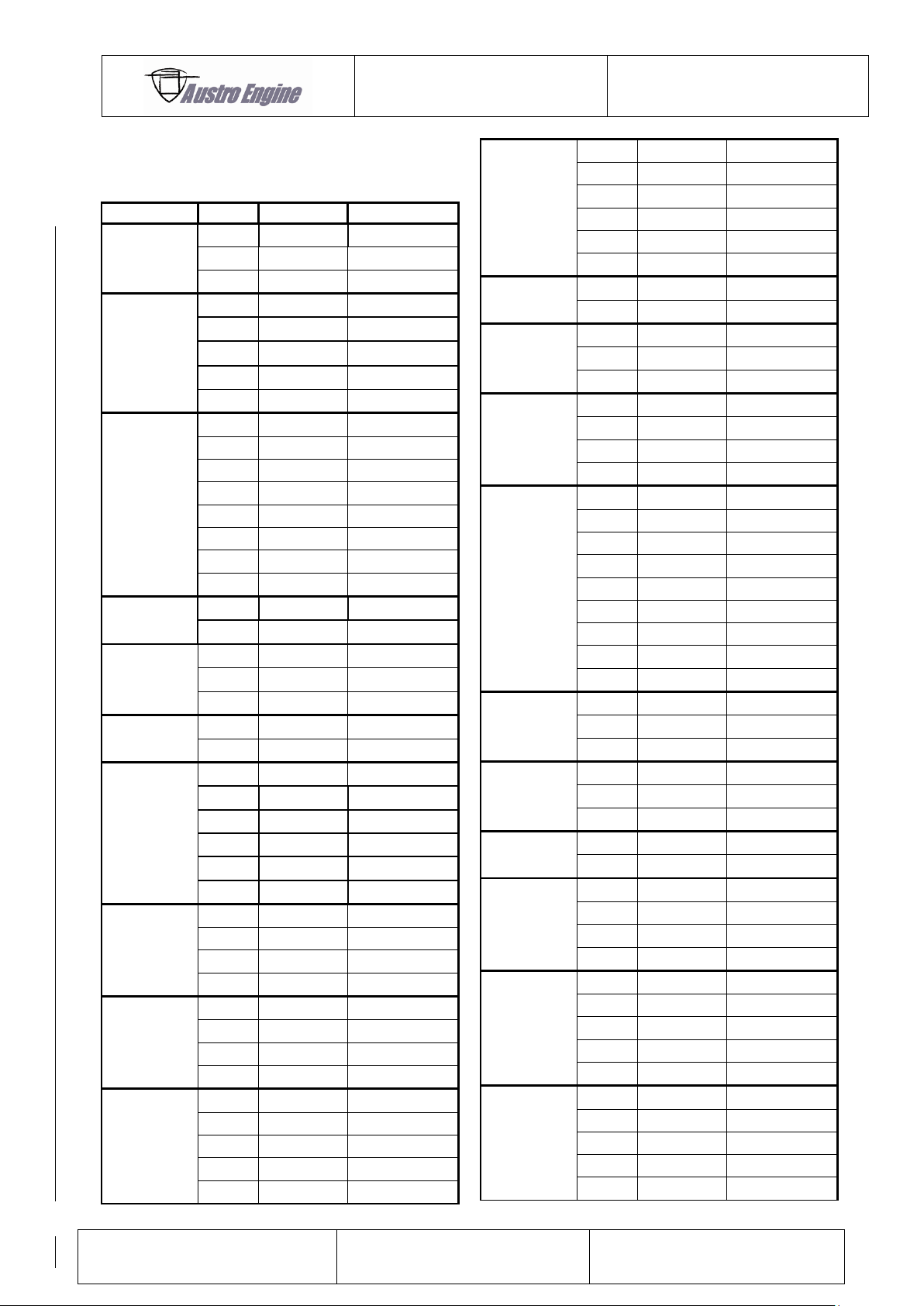
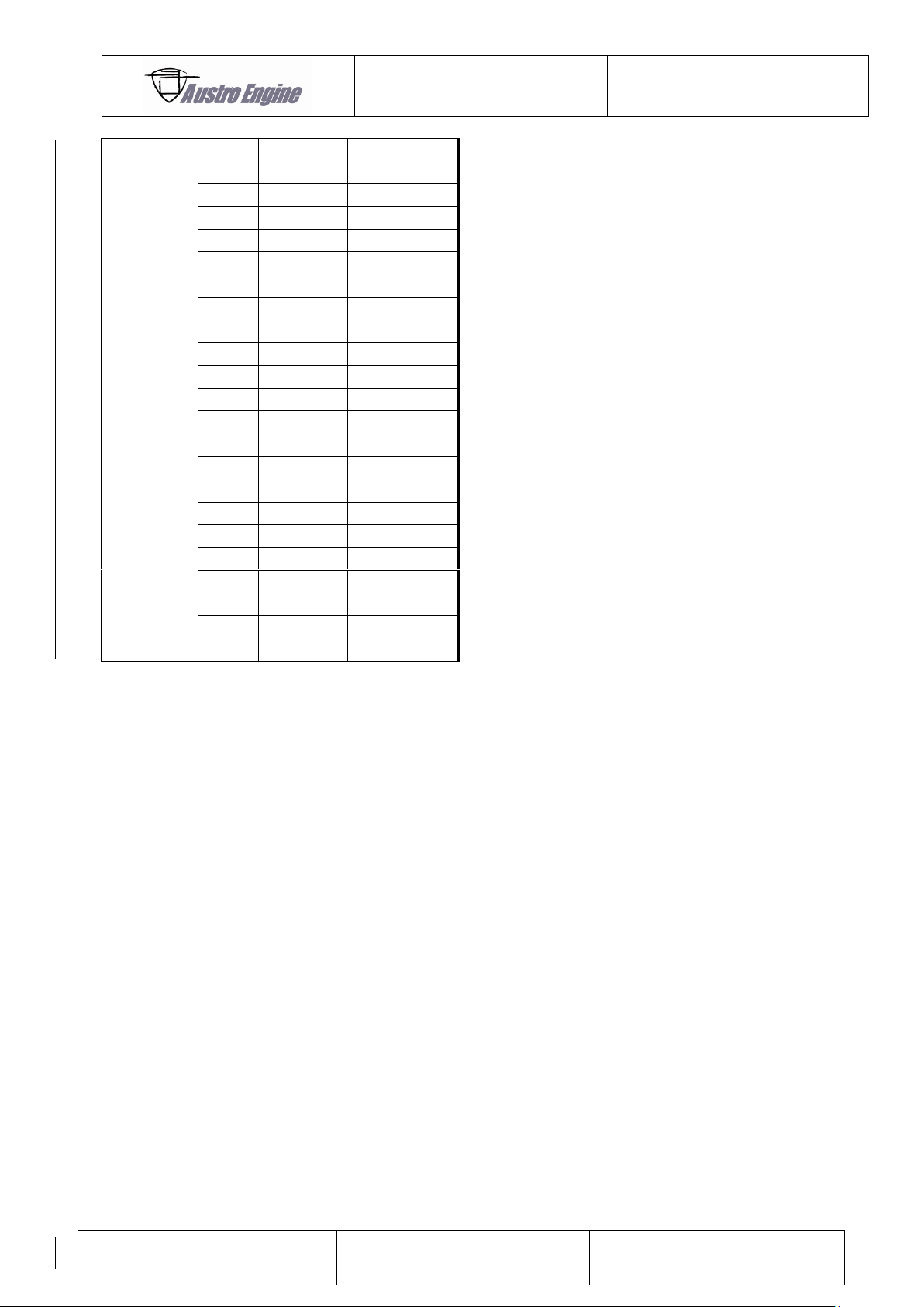
1.3 List of Valid Pages
Page 13
ENGINE MANUAL
IAE50R – AA
E1.01.05 – E
Issue date: 25.Jan.2018
Page: 1-6
Revision no: 9
6
9
25.Jan.2018
7
9
25.Jan.2018
8
9
25.Jan.2018
9
9
25.Jan.2018
10
9
25.Jan.2018
11
9
25.Jan.2018
12
9
25.Jan.2018
13
9
25.Jan.2018
14
9
25.Jan.2018
15
9
25.Jan.2018
16
9
25.Jan.2018
17
9
25.Jan.2018
18
9
25.Jan.2018
19
9
25.Jan.2018
20
9
25.Jan.2018
21
9
25.Jan.2018
22
9
25.Jan.2018
23
9
25.Jan.2018
24
9
25.Jan.2018
25
9
25.Jan.2018
26
9
25.Jan.2018
27
9
25.Jan.2018
Page 14
ENGINE MANUAL
IAE50R – AA
E1.01.05 – E
Issue date: 25.Jan.2018
Page: 1-7
Revision no: 9
Temporary Revision Number
Title of Temporary Revision
E10105-EM-TR-MDC-E1-163
Rotor Cooling Air Outlet Temperature
Measuring Position
1.4 List of Incorporated Temporary Revisions
Page 15
ENGINE MANUAL
IAE50R – AA
E1.01.05 – E
Issue date: 25.Jan.2018
Page: 2-1
Revision no: 9
2 GENERAL INFORMATION
Every reasonable effort has been made to ensure that the information contained in this
publication is correct when going to print.
However, as Austro Engine GmbH policy is one of continuous improvement, the information
given here may be superseded over a period of time by manual revisions or temporary by
Service Bulletins.
Page 16
ENGINE MANUAL
IAE50R – AA
E1.01.05 – E
Issue date: 25.Jan.2018
Page: 3-1
Revision no: 9
3 SAFETY INFORMATION
The instructions in this manual have been compiled to assist pilots and personnel responsible
for maintenance in the correct operation of the engines produced by Austro Engine GmbH.
Only correct operation and maintenance can ensure optimum availability throughout engine
life.
No recommendation in this manual absolves operators from compliance with any official
directive that may be issued by the controlling aviation authority of any country concerned, or
with any relevant Austro Engine GmbH Service Bulletins.
Austro Engine GmbH personnel are always happy to answer queries or give advice on
individual service problems. All queries to Austro Engine GmbH should be accompanied by
details of the engine model and serial number, hours operated and any other relevant
information.
3.1 Safety Symbols
The following symbols and warning signs are used in this manual to point out important
instruction. They must be observed strictly to prevent personal injury and material damage, to
insure operational safety of the aircraft and to avoid any damage to the aircraft as a result of
incorrect handling.
Disregarding these safety rules can cause personal injury or even death.
Disregarding these special instruction and safety measures can damage the
engine or other components.
The maintenance intervals must be strictly observed. When the service is not executed in
accordance to this manual Austro Engine GmbH will reject any warranty claims.
Additional note or instruction for better understanding of an instruction.
Page 17
ENGINE MANUAL
IAE50R – AA
E1.01.05 – E
Issue date: 25.Jan.2018
Page: 3-2
Revision no: 9
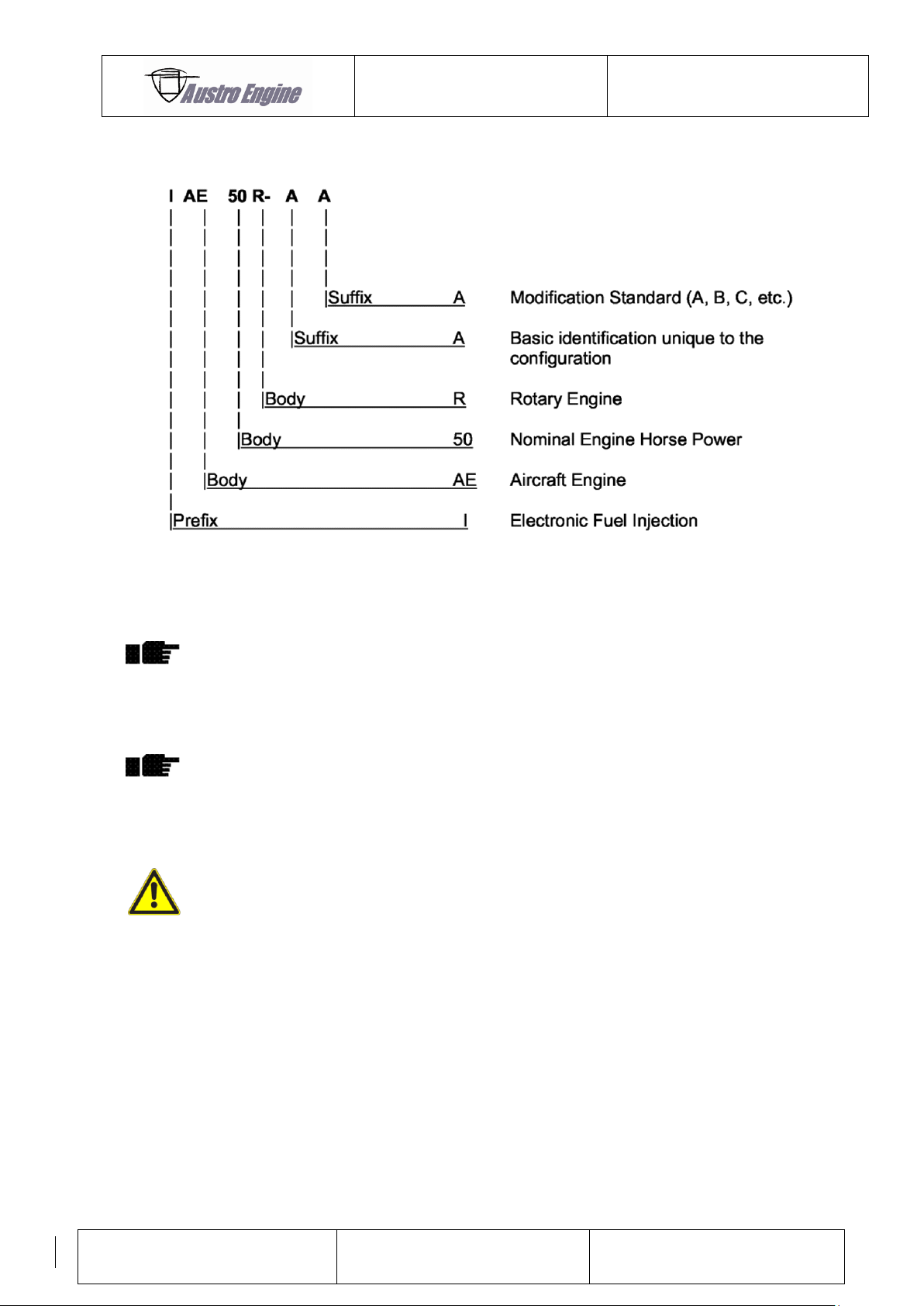
3.2 Model Designation Breakdown
3.3 Replacement parts
It is strongly recommended that only genuine, quality–
assured, replacement spare parts are used when carrying
out maintenance operations on this engine.
The use of parts not approved by Austro Engine GmbH may
significantly affect the performance, reliability and life of
the engine and may hazard the operator.
The use of parts not approved by Austro Engine GmbH may
invalidate the Engine Certification.
Page 18

ENGINE MANUAL
IAE50R – AA
E1.01.05 – E
Issue date: 25.Jan.2018
Page: 4-1
Revision no: 9
4 RESERVED
Page 19
ENGINE MANUAL
IAE50R – AA
E1.01.05 – E
Issue date: 25.Jan.2018
Page: 5-1
Revision no: 9
5 GENERAL ENGINE DATA
5.1 Description
Wankel type rotary, single rotor, dual spark ignition, liquid cooled rotor housing, forced air
cooled rotor, ECU, normal aspirated.
5.2 Technical data
5.2.1 Design Responsibility
Austro Engine GmbH
Rudolf – Diesel – Straße 11
2700 Wiener Neustadt
Austria
5.2.2 Certification
Refer to Engine Type Certificate Data Sheet No EASA.E.085.
Page 20
ENGINE MANUAL
IAE50R – AA
E1.01.05 – E
Issue date: 25.Jan.2018
Page: 5-2
Revision no: 9
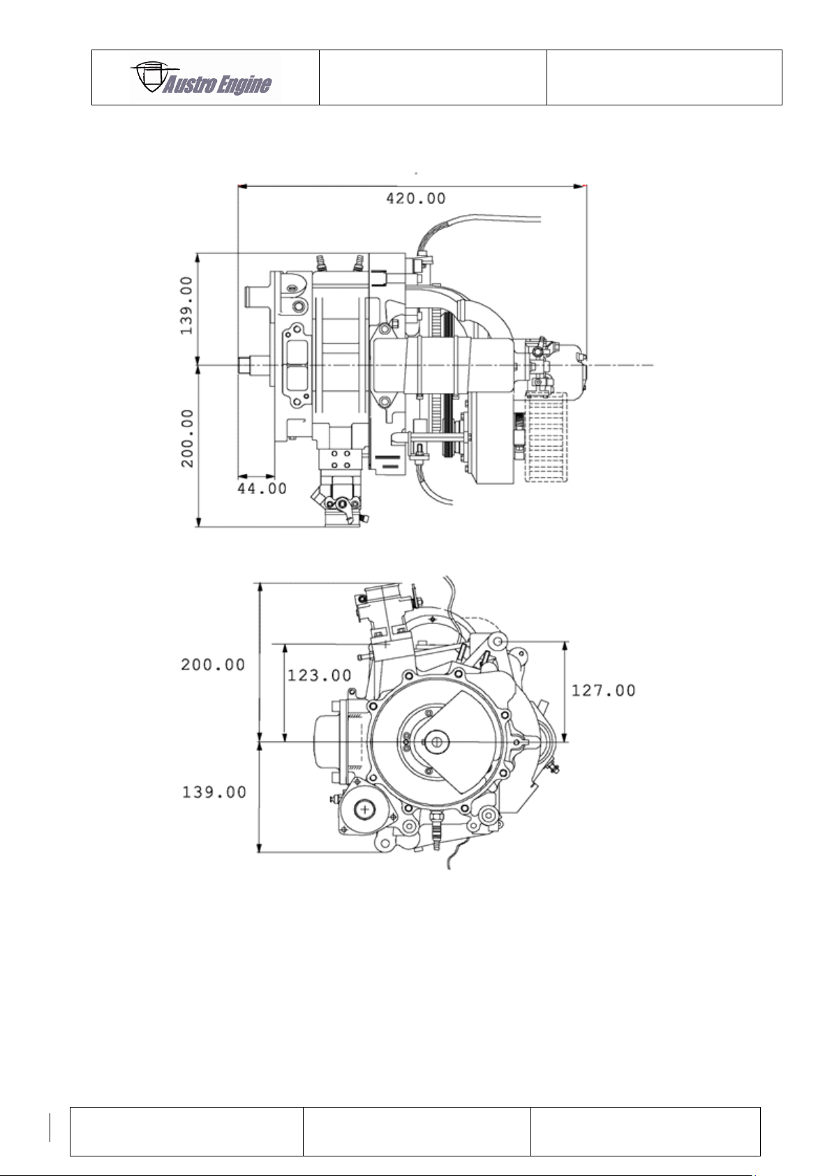
5.2.3 Engine Overall Dimensions
Fig. 1: Engine overall dimensions
Page 21
ENGINE MANUAL
IAE50R – AA
E1.01.05 – E
Issue date: 25.Jan.2018
Page: 5-3
Revision no: 9
5.2.4 Engine Particulars
Design Single rotor Wankel–type rotary engine
Eccentricity 11.6 mm
Width of Housing 68.2 mm
Generating Radius 69.0 mm
Compression Ratio 9 : 1
Swept Volume 294 ccm
Rotor billet steel internally cooled by a belt driven
centrifugal fan.
Main and End Housing Aluminum alloy castings, cooled with a pump
circulated pressurized water–glycol mixture and
supporting an optional oil separator assembly
(supplied by the installer mounted directly onto the
outlet casting).
Eccentric Shaft Hardened and ground alloy steel. The complete
rotating assembly is in full dynamic balance to
minimise vibration, achieved by counter weighting
each end of the assembly. Both the main and rotor
bearings are rolling element types.
Flywheel billet steel fitted with an induction–hardened steel
starter ring gear.
5.2.5 Out – put Drive
Take from the eccentric shaft via a woodruff key.
Rotation Direction The eccentric shaft rotate in a clockwise direction
when viewed from the driving side of the engine.
5.2.6 Net Dry Weight
Approximately 59.5 lbs. (27 kg)
Page 22
ENGINE MANUAL
IAE50R – AA
E1.01.05 – E
Issue date: 25.Jan.2018
Page: 5-4
Revision no: 9
5.2.7 Cooling
Approximately 90% of surplus heat is rejected into
the liquid cooling system; the balance is rejected via
rotor cooling air.
Coolant 50 : 50 Distilled Water – Ethylene Glycol mix
Silkolene PRO–COOL (or equivalent)
5.2.8 Fuel Specification
AVGAS 100LL
EUROSUPER, ROZ 95, in accordance with EN228
or equivalents.
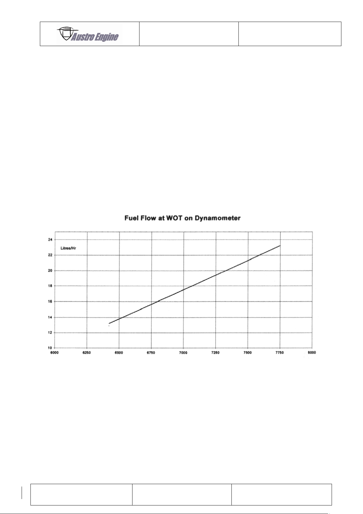
5.2.9 Fuel Consumption Curve
Fig. 2: Fuel consumption curve
Note that these values are taken from JAR 22 calibration test results and are not indicative of
actual consumption rates.
Typical in–flight fuel flows, particularly at part–throttle conditions, may be expected to be
significantly lower.
Page 23
ENGINE MANUAL
IAE50R – AA
E1.01.05 – E
Issue date: 25.Jan.2018
Page: 5-5
Revision no: 9
5.2.10 Pressure to Fuel Injector
Nominal 3 bar, operation range 2.8 bar to 3.2 bar
Controlled by a pressure regulator.
5.2.11 Lubrication
Lubrication of all bearings and rubbing surfaces is
achieved via two lines from the oil metering unit
driven off the water pump. The flow rate of the
metering unit is calibrated and must not be adjusted.
Use only approved engines oils.
Oil Separator An optional oil separator is recommended. The
separator is to be supplied by the engine installer.
5.2.12 Oil Specification
SILKOLENE Comp 2 Premix
SILKOLENE Classic 2T Premix
CASTROL XR77 (EMPA specification 417478/01)
CASTROL Power 1 Racing 2T (API TC+, JASO FD, ISO EGD)
AEROSHELL Oil Sport Plus2 (API TC)
The use of SILKOLENE Comp 2 Injector is NOT allowed.
Page 24
ENGINE MANUAL
IAE50R – AA
E1.01.05 – E
Issue date: 25.Jan.2018
Page: 6-1
Revision no: 9
6 OPERATING DATA / LIMITATIONS
Static sea level ratings under the following conditions:
- International Standard Atmospheric conditions at sea level
- Generator functioning
- Liquid coolant outlet temperature 65 °C (± 5 °C)
- Standard induction pipe fitted with filter
- Power measured at eccentric shaft output
- Approved fuels
- Test bed exhaust used
6.1 Maximum Take – off Rating
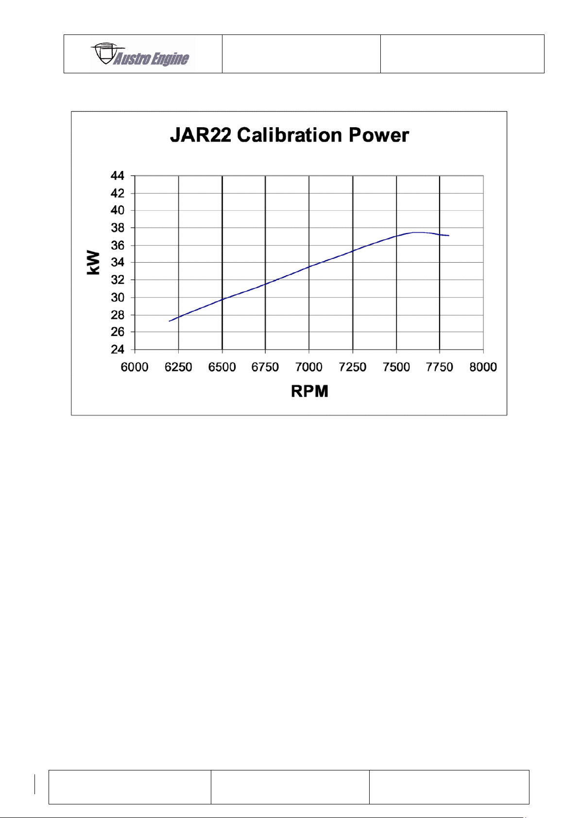
Max. T/O – Power (minimum) 37.3. kW (50 BHP)
(Value quoted includes losses associated
with intake exhaust conditions specified.)
Max. T/O – RPM 7 750 RPM
Fuel consumption (max) 24 liters / hr
Exhaust back pressure 0.21 bar ± 0.04 bar (3 psi ± 0.5 psi)
at 7750 RPM with test bed system
6.2 Maximum Continuous Rating
Max. Cont. Power 35.8 kW (48 BHP)
Max. Cont. rpm 7 100 RPM
Fuel consumption (max) 18 liters / hr
Page 25
ENGINE MANUAL
IAE50R – AA
E1.01.05 – E
Issue date: 25.Jan.2018
Page: 6-2
Revision no: 9
6.2.1 Power Curve
Fig. 3: Typical power curve
6.3 Operating Limitations
6.3.1 Engine RPM
Maximum for take–off ( for 3 mins) 7 750 RPM
Maximum Continuous 7 100 RPM
Maximum Overspeed (20 sec. limit) 8 000 RPM
Idle Minimum 2 500 RPM
6.3.2 Ambient Temperature Limits
Minimum Starting Ambient (without priming) -10 °C
Maximum Ambient +55 °C
Page 26
ENGINE MANUAL
IAE50R – AA
E1.01.05 – E
Issue date: 25.Jan.2018
Page: 6-3
Revision no: 9
6.3.3 Liquid Coolant Temperature Limits
Maximum for Take–off 100 °C
Minimum for Take–off 60 °C
Maximum continuous 90°C
6.3.4 Rotor Cooling Air Outlet Temperature Limits
Maximum for Take–off (3 minutes) 120 °C
Maximum Continuous 110 °C
The specified Rotor Cooling Air Outlet (RCAO) Temperature Limits for the given engine
ratings are valid for the measuring position defined by Austro Engine GmbH. For detailed
information refer to chapter 19.3.2.
For an installation of a RCAO temperature sensor different from the sensor position defined
by Austro Engine, contact Austro Engine GmbH for specification of applicable limits (e.g. by
means of a reference test).
6.3.5 Exhaust Gas Temperature (EGT)
Maximum Exhaust Gas Temperature 970 °C
6.3.6 Fuel Pressure
Nominal Fuel Pressure 3 bar (43.5 psi)
Fuel Pressure Tolerance ± 0,2 bar (± 2.9 psi)
6.3.7 Altitude
The engine has been tested for use up to 14.000 ft pressure altitude
6.4 Manuals
Operation / Maintenance / Installation Doc. No. E1.01.05–E
Overhaul Manual MWE (D) 085
Page 27
ENGINE MANUAL
IAE50R – AA
E1.01.05 – E
Issue date: 25.Jan.2018
Page: 7-1
Revision no: 9
7 COMPONENTS
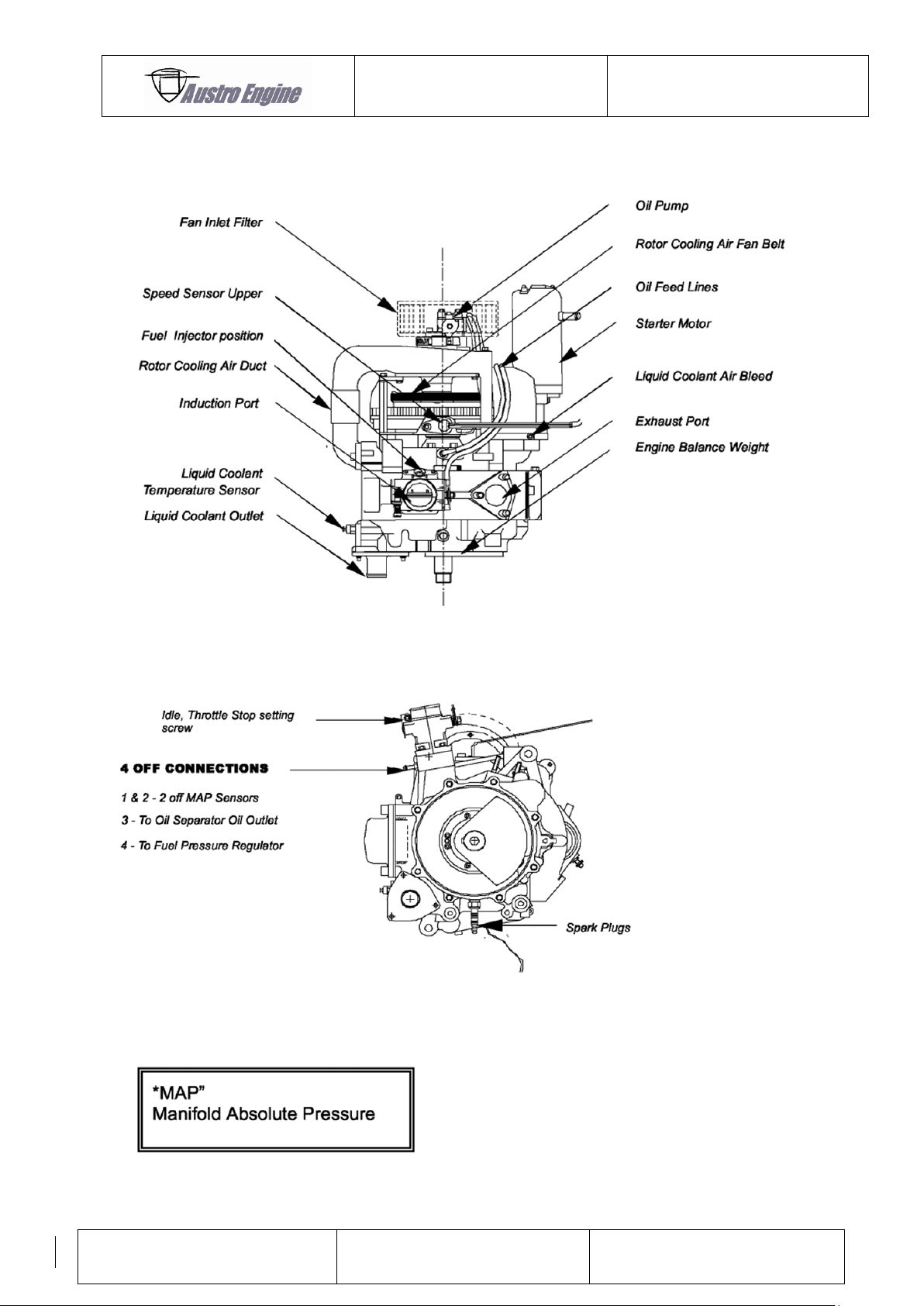
Fig. 4: Location of components
Fig. 5: Location of components
Page 28
ENGINE MANUAL
IAE50R – AA
E1.01.05 – E
Issue date: 25.Jan.2018
Page: 7-2
Revision no: 9
7.1 Description of Components
7.1.1 Rear Assemblies
These assemblies comprise of a back plate, with integral mounting lugs, water pump,
alternator, speed sensors, rotor cooling air fan assembly, oil pump and starter motor.
7.1.2 Front Assemblies
The front assemblies comprise of a water cooled end plate, temperature transmitter.
7.1.3 Centre and Rotating Assembly
The centre assembly comprises a rotor housing with passageways for liquid cooling. Externally
is the throttle body with fuel injector, spark plugs, and exhaust flange and, internally, the
eccentric shaft and rotor assembly.
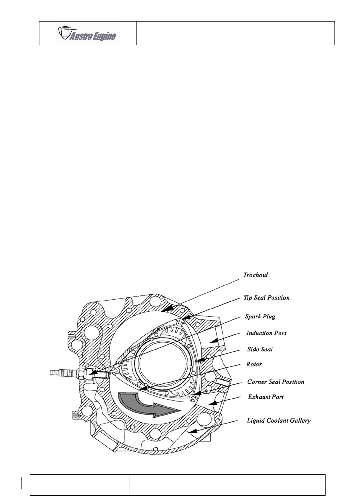
7.1.4 Rotor Sealing
Rotor sealing is provided by the tip seals, side seals and corner seals with each seal being
spring loaded outwards. The corner seals placed at the junction of the side and tip seals
provide sealing at these critical locations.
Fig. 6: Rotor sealing
Page 29
ENGINE MANUAL
IAE50R – AA
E1.01.05 – E
Issue date: 25.Jan.2018
Page: 8-1
Revision no: 9
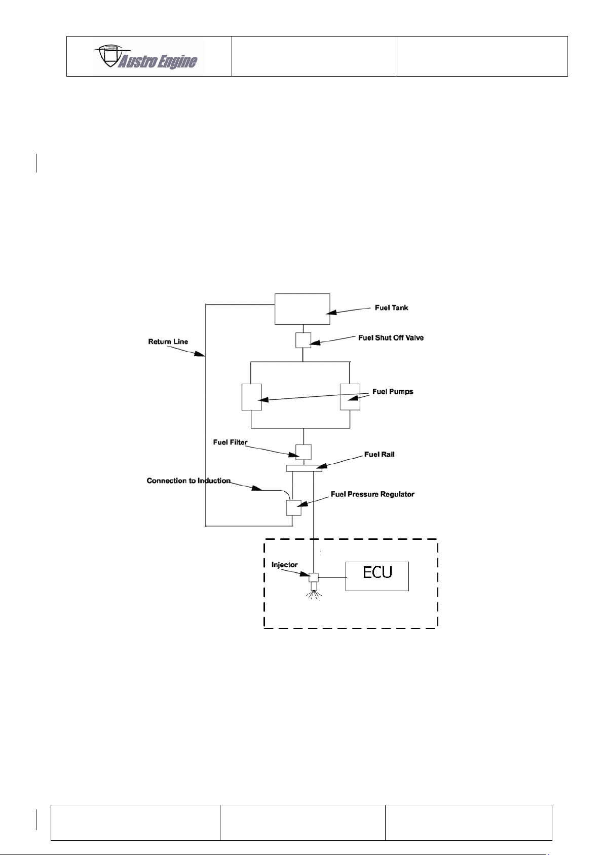
Provided by AE as part of the engine
8 DESCRIPTIONS OF SYSTEMS
8.1 Fuel System
The fuel injector requires clean fuel at 3 bar ± 0.2 bar with a minimum return flow of 80 liters
per hour.
Continuous circulation of fuel trough the rail removes heat from the injector and reduces the
risk of vapor locking.
8.1.1 Typical Schematic Fuel System (provided by engine installer)
Fig. 7: Typical schematic of fuel system
8.1.2 Throttle Valve Setting
As a flight safety measure, the throttle valve is set to return to wide–open throttle position by
the return spring in the event of disconnection from the throttle cable.
A spring–loaded adjuster screw on the throttle body controls idle speed setting.
Page 30
ENGINE MANUAL
IAE50R – AA
E1.01.05 – E
Issue date: 25.Jan.2018
Page: 8-2
Revision no: 9
8.2 Cooling System
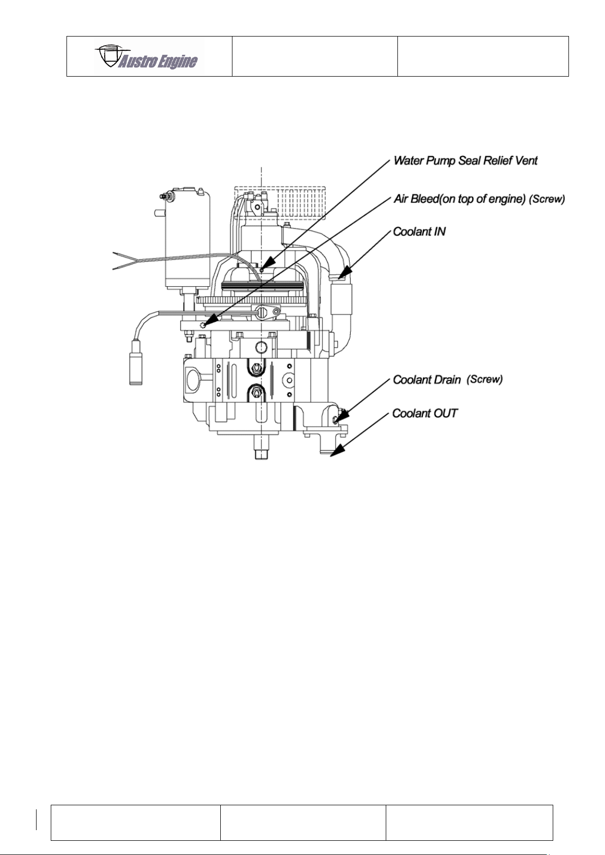
8.2.1 Liquid Cooling System
Fig. 8: Coolant circuit items
8.2.2 Water Pump
A water pump impeller, driven from the eccentric shaft via a tufnol drive coupling (a shear
point) is mounted at the rear of the engine and circulates coolant through the engine casting
and radiator.
8.2.3 Temperature Regulation
No thermostat is fitted. A minimum coolant temperature of 60 °C must be maintained and a
normal operating temperature of 70 °C is desirable.
Page 31
ENGINE MANUAL
IAE50R – AA
E1.01.05 – E
Issue date: 25.Jan.2018
Page: 8-3
Revision no: 9
8.2.4 Coolant
Coolant is a 50 / 50 water – ethylene glycol mix. For details refer to Chapter 5.2.7
The use of a pre–mix solution such as Silkolene Pro–Cool is
strongly recommended so that there is no variation in the
strength or the heat transfer properties of the coolant.
8.2.5 System Pressure
The cooling system is a closed loop system, designed for a working pressure of 0.9 bar
(13 psi) overpressure.
8.2.6 Air cooling system
Lubrication of the eccentric shaft rear bearings is achieved by direct injection of oil from the
metering oil unit and results in an oil mist being entrained into the rotor cooling air system.
The oil mist, in turn, lubricates the rotor bearing, front main bearing and cools the inside of
the rotor.
Page 32
ENGINE MANUAL
IAE50R – AA
E1.01.05 – E
Issue date: 25.Jan.2018
Page: 8-4
Revision no: 9
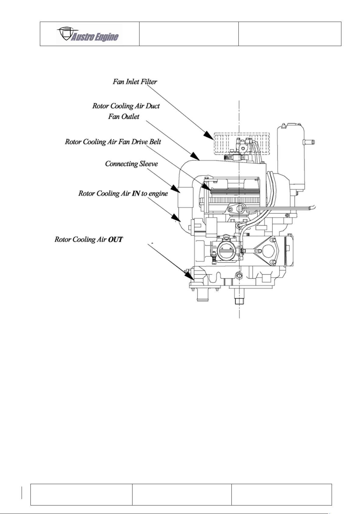
8.2.7 Rotor Cooling Air Parts
Fig. 9: Rotor cooling air parts
Page 33

ENGINE MANUAL
IAE50R – AA
E1.01.05 – E
Issue date: 25.Jan.2018
Page: 9-1
Revision no: 9
9 OPERATING THE ENGINE
9.1 Starting Procedure and Warm–up
Starting
The settings, start and warm–up procedures for the first start of a newly installed engine are
obviously to be treated with the greatest care. However, all engines supplied by Austro Engine
GmbH will have been fully run–in and performance–tested prior to shipping.
If the engine fails to start after three attempts (normal
maximum starter engagement per attempt of five seconds)
there is something incorrect!
(Fuel, ignition, or outside air temperature).
Starting between -5 °C and below may require assistance
for the aircraft battery!
1) Check coolant level
2) Check engine oil tank level is sufficient for flight / test
3) Check fuel level, fuel condition (no water contained); set fuel master “ON”
4) Set throttle slightly off the idle stop.
5) Switch on battery and alternator.
6) Switch on ignition – verify that all gauges / alarms are correct.
7) Switch on both fuel pumps – verify that all gauges / alarms are correct.
8) Switch on one ECU supply – verify error light on continuously (switch off).
9) Switch on second ECU supply and verify error light on continuously (switch off).
10) Switch on both ECU supplies and verify error light on continuously.
Ensure all personnel are clear of propeller and aware that
the engine is to be started.
9) Crank the engine for 5 seconds (or less if the engine starts).
10) If the engine fails to start, recheck switch positions and alarms.
11) If cold start – repeat (9) at 15 second intervals.
12) (See NOTES above for starting limitations).
13) Allow engine to warm up at approximately 3 000 RPM to 50 °C.
14) Check that the rpm rise is smooth and trouble free.
15) A sudden liquid coolant temperature rise indicates air trapped in the coolant system.
In this case the bleed procedure should be carried out (see 13.3)
Page 34
ENGINE MANUAL
IAE50R – AA
E1.01.05 – E
Issue date: 25.Jan.2018
Page: 9-2
Revision no: 9
During cold starts not more than 5 x 5 second start attempts
in any 3 minute period.
9.2 Engine Start down to approximately -10 °C
The engine will start equally well with either permitted fuels.
9.3 Ground Tests
See chapter 15.
9.3.1 Full Power Check
Set WOT and note RPM achieved in relation to the minimum acceptable value as defined in
the aircraft operating manual. Check that all instrumentation is functioning and that all
parameters are within limits. Check that single ignition drops are less than 300 RPM at 6 200
RPM.
Page 35
ENGINE MANUAL
IAE50R – AA
E1.01.05 – E
Issue date: 25.Jan.2018
Page: 9-3
Revision no: 9
9.3.2 Idle Check
Fully close the throttle and note rpm; it should be 2,500 RPM ± 100 RPM. Adjustment, if
required, is by the throttle stop screw on the throttle body. For method, and precautions, see
the aircraft manufacturer’s manual.
9.3.3 Stopping the Engine
It is usual to idle the engine for 2 to 3 minutes before stopping (to dissipate internal heat prior
to shut down) [see aircraft manufacturers operating manual].
Switching off either the ECU power, or ignition switches, or the fuel pumps will stop the
engine. The latter gives a short run down and dissipates pressure in the fuel lines.
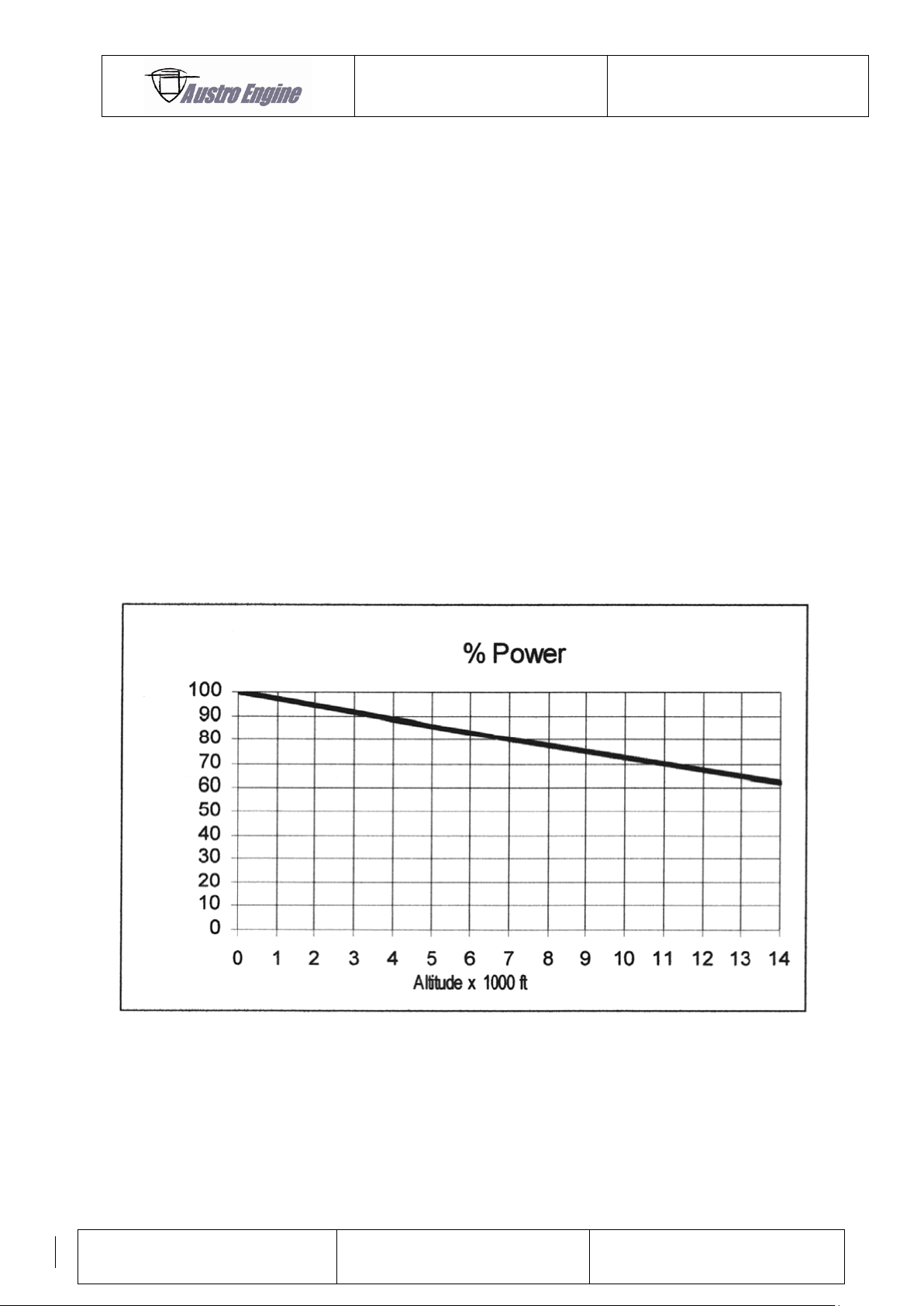
9.4 Power Loss at Altitude
Performance at altitude is degraded due to a reduction in air density. The approximate power
available (at given RPM / throttle setting) is given in 6.2.1 for Sea Level.
Fig. 10: Power loss at altitude
Page 36
ENGINE MANUAL
IAE50R – AA
E1.01.05 – E
Issue date: 25.Jan.2018
Page: 9-4
Revision no: 9
9.5 Storage
General (installed engine).
Proper steps must be taken, on engines used infrequently, to lessen the possibility of
corrosion. This is especially true if the aircraft is based near the sea coast or in areas of high
humidity.
In all geographical areas the best method of preventing corrosion of internal parts of the
engine is to fly the aircraft at least once a week. Alternatively the engine should be run long
enough to reach normal operating temperatures.
9.5.1 Storage up to 90 Days
No special treatment is required for storage periods of up to 90 days.
The aircraft should be protected from the weather and excessively damp conditions.
9.5.2 Storage beyond 90 Days
The following procedures may require that the engine is
removed from the aircraft – see aircraft manufacturer’s
instructions.
Never rotate the engine with the oil can nozzle still in the
spark plug or exhaust / inlet ports!
1) To protect the internal of the engine it is recommended that additional engine oil be
introduced. This can, for example, be via the spark plug holes, the throttle body or
the exhaust and is determined by the aircraft manufacturer.
2) Where appropriate, ensure all electrical circuits are off, and then manually rotate the
propeller shaft and engine.
3) Inject 5cc of the prescribed engine lubrication oil through either spark plug hole in the
rotor housing. (See CAUTION! above)
4) Rotate the engine through 1 revolution of the flywheel (by turning the propeller or
propeller shaft and hence the eccentric shaft, by hand).
5) Repeat (3 & 4) five times.
6) Rotate the engine through 6 revolutions of the flywheel then refit the spark plugs.
7) Seal all inlets and exhaust openings to prevent moisture ingress.
Page 37
ENGINE MANUAL
IAE50R – AA
E1.01.05 – E
Issue date: 25.Jan.2018
Page: 9-5
Revision no: 9
8) To protect the bearings and associated parts, engine oil should be introduced into the
area. The aircraft manufacturer describes the method by which this is achieved and
the instructions must be followed carefully.
9) Blank off all open holes.
10) To protect the outside of the engine, anti corrosion oils of well–known oil companies
are recommended, such as:
Anticorit 5 of Messrs FUCHS, D – 6600 Mannheim, Germany
Lubrication Oil MTL – L – 644 B of MOBIL–OIL
Shell ENSIS Fluid 2360 of SHELL
RUST BAN 395 of ESSO
It is also ESSENTIAL that the fuel system be drained.
Items (1) to (3) should be carried out every 90 days.
9.5.3 Returning to Service from Storage
1) Restore the engine to operation according to the Aircraft Manufacturers instructions.
2) If the aircraft been laid–up for more than 6 months, please carry out 9.5.2 ((1) to
(6)).
3) Rotate the engine by hand several times to ensure that all excess oil is drained via the
spark plug holes.
4) Clean and refit, or replace, the spark plugs.
5) Check the engine for external damage or deterioration suffered during storage, and
rectify as necessary.
6) Clean engine to remove inhibitor and remove all storage blanks.
7) Refit engine in accordance with the aircraft manufacturer’s instructions.
Stale fuel must NOT be reused!
Page 38
ENGINE MANUAL
IAE50R – AA
E1.01.05 – E
Issue date: 25.Jan.2018
Page: 10-1
Revision no: 9
10 ENGINE EMERGENCY PROCEDURES
10.1 Fan Belt Failure
In the unlikely event of a fan belt failure, the indication will be a sudden rise in Rotor Cooling
Air temperature. The engine load / rpm should be reduced as much as is practical to prevent
further heat build-up. If the rotor cooling outlet air temperature reaches 130 °C the engine
should, if possible, be switched off. Continued running of the engine under these conditions
will cause damage.
10.2 Low Oil in the Tank
In the unlikely event of low oil alarm the engine RPM should be reduced as much as is
practical. Flying time should be limited to a total of 10 minutes at this reduced power. Flying
under such conditions may cause damage to the engine.
10.3 Low Fuel Pressure
If low fuel pressure is indicated, the engine may stop or operate at reduced power and may
also indicated an excessively high exhaust temperature. Throttle setting should be adjusted, if
practical, to minimise excess temperature.
Continued operation at excess exhaust temperature will cause damage to the engine.
10.4 Rotor Cooling Air Temperature
If the rotor cooling air temperature rises above the specified limit, the engine should be shut
down as soon as possible. Continued operation at excess temperature is likely to cause
damage to the engine.
10.5 Coolant Temperature
If the coolant temperature rises above the specified limit, the engine should be shut down as
soon as possible. Continued operation at excess temperature is likely to cause damage to the
engine.
Page 39
ENGINE MANUAL
IAE50R – AA
E1.01.05 – E
Issue date: 25.Jan.2018
Page: 11-1
Revision no: 9
4 mm
2.0 Newton-meters (Nm)
5 mm
4.5 Nm
6 mm
8.5 Nm
8 mm
21.5 Nm
10 mm
30.0 Nm
Spark Plug
10.0 Newton-meters (Nm)
Coolant Temperature Sender
4.5 Nm
Starter Motor Terminal
8.0 Nm
Oil Pump Inlet Fitting
2.5 Nm (caution)
Oil Pump Outlet Banjo
2.5 Nm (caution)
Oil Pipe Nut & Olive
3.0 Nm (caution)
11 MAINTENANCE NOTES
11.1 Austro Engine GmbH Available Consumables
R1A-06-000-803 Rotor Cooling Air Filter
R1A-06-000-805 Induction Air Filter
Engine Oil see Chapter 5.2.12
Glysantin Aluprotect Premium Engine Coolant (One Litre Container)
Copper ease Copper ease
Loctite 243 Screw Locking
Loctite 595 Sealing silicone
R1A-09-000-801 Spark Plug (NGK)
K&N Filter Oil Air Filter Oil
R1A-30-000-801 Injector
For further part replacement contact Austro Engine GmbH.
11.2 General Torque Settings
Bolts / Socket Head Cap Screw
Nuts and Stiff Nuts – as above.
11.2.1 Specific Torque Settings
Page 40
ENGINE MANUAL
IAE50R – AA
E1.01.05 – E
Issue date: 25.Jan.2018
Page: 11-2
Revision no: 9
11.2.2 MAP Hoses
Remove all MAP hoses and clips and clean out any oil. Make sure that they are dry before
placing them back onto the engine.
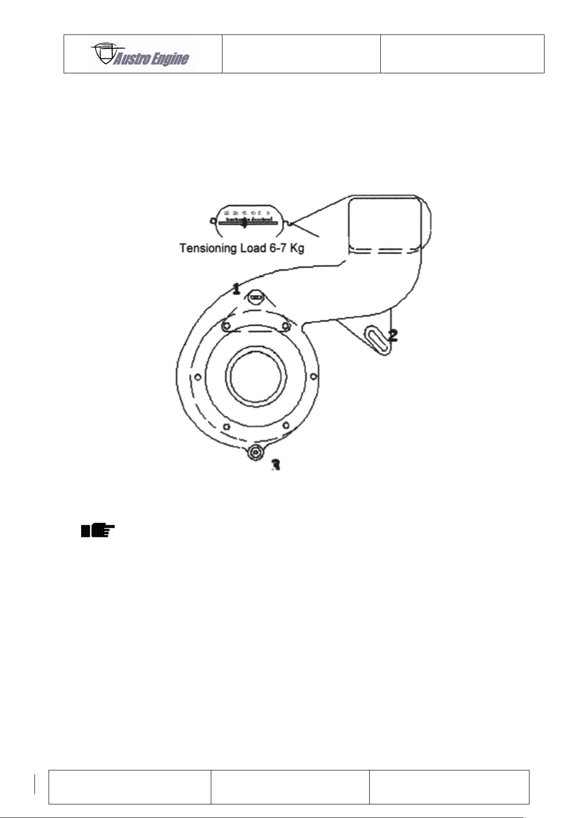
11.2.3 Checking & Setting Fan Belt Tension
Fig. 11: Belt tension
The silicon rubber tube and the tie wraps are left in place
during the test.
1) Slacken the three attachments numbered 1, 2 and 3 above.
2) Attach a loop of suitable material around the fan outlet duct.
3) Using a suitable spring balance, apply a force to the loop of 6 – 7 Kilograms.
4) With this force still applied, tighten the 3 housing attachments (with 8 lbft/11 Nm).
5) Confirm the attachments are not at the end of their adjustment slots.
6) If a new belt is required, see Section 13.5.2
11.2.4 Adjusting engine idle speed
For adjusting procedure, and precautions, see the aircraft manufacturer’s instructions.
Page 41
ENGINE MANUAL
IAE50R – AA
E1.01.05 – E
Issue date: 25.Jan.2018
Page: 12-1
Revision no: 9
ITEM
Check A
(every flight)
Check B
(every flying day)
Every 50 hrs
or annually
Every 150 hrs
or 3 years
Section
Reference
Engine oil level / coolant
level check
X X X
X
Aircraft Manual
Coolant leak check
X X
X
13.4
Insp. / clean / replace air
filters
X
X
13.5.4
Insp. engine, mountings and
all external fasteners
X
X
Aircraft Manual
Check fan belt condition &
tension
X
X
13.5.1
Check cooling system
condition and security,
X
X
13
Inspect / clean / replace
spark plugs
X
X
14.1
Full engine ground run
X
X
15
Coolant pressure test
X
X
13.4
Renew coolant
X
13.3
End plates – examine seals
& seal faces
X
14
Inspect fan impeller
(300 hours)
13.5.5
Replace fan belt (earlier of
300 hrs or 10 yearly)
13.5.2
Replace in line fuel filter
X
Aircraft Manual
Clean & inspect MAP hoses
and clips
X
11.2.2
Replace fuel injector
(150 hrs or 10 yearly)
Aircraft Manual
Continuity of ECU earth
straps outer case (2)
X
Aircraft Manual
Continuity of ECU loom
ground connections (2)
X
Aircraft Manual
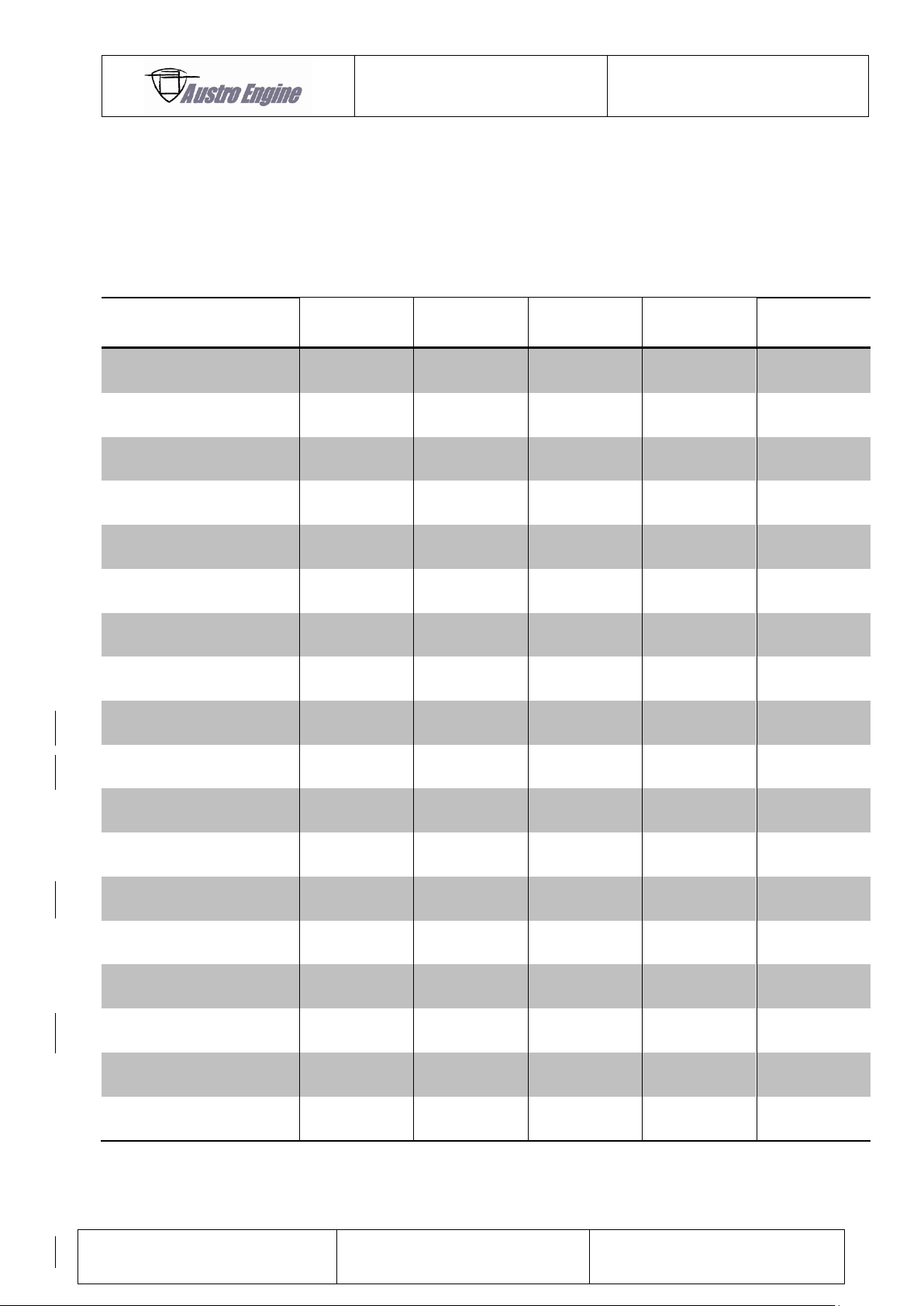
12 SCHEDULED MAINTENANCE
12.1 Maintenance Schedule
ALL HOURS QUOTED ARE ENGINE HOURS
Page 42
ENGINE MANUAL
IAE50R – AA
E1.01.05 – E
Issue date: 25.Jan.2018
Page: 12-2
Revision no: 9
11
Starter Ring – rotate engine via prop
Chipped or missing teeth
12
Generator Cables
Signs of contact and chafing/cracking
13
Lower Timing Sensor and cables
Signs of contact and chafing/cracking
14
Water Pump Housing
Vent hole
15
Upper Timing Sensor and cables
Signs of contact and chafing/cracking
16
Fan Housing
Cracks
17
Fan Belt
Check tension and condition
18
Fan Filter – remove and check
View Fan Impeller – Debris – Cracks
19
Engine Mounts – port side
Nuts, bolts
20
Fuel Rail, Injector, Pressure Regulator
Leaks – Cracks – Cable Connection
21
Linkage, Throttle Stops
22
Ram pipe
Check temperature sensor connection
23
Induction Air Filter
Cleanliness and damage
24
Rotor Housing drain screw
Security – Leaks
25
Exhaust System - complete
Overheat adjacent parts – Security
26
ECU and cables
Signs of deterioration
27
Voltage Regulator and cables
Signs of deterioration
REF
ITEM
CHECKS / COMMENTS
1
Water Outlet Cover
Leakage
2
Water Hoses
Security of all clips – Leaks
3
Oil Separator
Leakage and temperature sensor connection
4
Oil Pump – Lines and Terminations
Leakage
5
Spark Plug Coils and Plug Caps
Cables and terminations
6
Spark Plug Condition
Connection & gap area
7
Engine Mounts – Starboard Side
Nuts, bolts secure
8
Starter Motor Mounts and Cable
Bolts and cable connections
9
Starter Pinion – Condition and
Laxity
Teeth, free movement, play
10
Generator (Stator / Rotor)
Note any debris in the area
12.2 Typical 50 Hours Check
Visual checks only unless stated! All checks to include fastenings, cracking,
leaks, discoloration and wire locking!
Ensure that all switches are OFF before rotating the engine.
Page 43
ENGINE MANUAL
IAE50R – AA
E1.01.05 – E
Issue date: 25.Jan.2018
Page: 12-3
Revision no: 9
28
ECU Sensors and Cables
Signs of Deterioration
29
Engine Alarms, Transducers and Cables
Signs of Deterioration
30
Oil Tank and Vent
Security – Leaks – Level - Connections
31
Radiator and Overflow Tank
Security – Damage – Leaks – Debris –
Level
32
Oil Separator Hoses
Leakage
33
Rotate Propeller by Hand
Check 6 x compression on prop
Carry out engine ground run according to check list!
12.3 Mandatory Life Limitation
There is no life limit of the engine, engine operation is on condition.
Reliable operation of this engine is dependent upon injector
replacement in accordance with maintenance
recommendations.
Lightning strikes may damage the ECU. Following any
lightning strike the ECU should be returned to Austro Engine
GmbH for checking.
Page 44
ENGINE MANUAL
IAE50R – AA
E1.01.05 – E
Issue date: 25.Jan.2018
Page: 13-4
Revision no: 9
13 COOLING SYSTEM
13.1 Liquid Cooling System
Coolant Level Check: Refer to Aircraft Manufacturer’s instructions.
In a fault free system, the coolant level will not alter significantly. Any unusual drop in the
coolant level in the tank indicates a fault in the system that must be rectified before further
flights.
13.2 Coolant leak check
Check all hoses for cracks, wear, security and leaks. (a white or light pink crust around a joint
is an indication of a leak!). Refer also to engine installer’s handbook. If a leak is found, replace
hose and hose clips, tighten hose–clips etc. as necessary and check / bleed / pressure test the
system as detailed below.
Check all bleeding points and, if visible without engine removal, all engine housings and
mating surfaces for leaks. Check water pump bleeding hole and engine bay for any coolant
residue. If any residue is found check engine until leak is found and contact Austro Engine
GmbH.
13.3 Coolant System Filling and Bleeding
This test should be done if leaks are suspected and after any
part of the coolant system has been disturbed and replaced.
This is a guide, any variations in the aircraft manual should
be followed!
1) Slowly fill the system with the coolant mix
2) Undo bleed plugs until fluid escapes, then tighten.
3) Top up radiator header tank with coolant mix.
4) Check for coolant leaks at all connections / interfaces.
In doubt fit a coolant pressure tester.
5) If required fit a coolant system pressure tester (Blue Point No STV 262 or similar) to
6) Recheck bleed points for air after the first engine run.
7) Repeat (6) until no further air is emitted from the bleed point(s) When running the
the header tank and pressure test.
engine ensure that coolant temperature rise is slow and consistent with warm up and
Page 45
ENGINE MANUAL
IAE50R – AA
E1.01.05 – E
Issue date: 25.Jan.2018
Page: 13-5
Revision no: 9
no sudden temperature jumps occur. If the coolant temperature suddenly rises then
there will still be entrained air in existence and the cycle must be repeated.
8) Top up header tank with coolant mix. Refit the filler cap and wire lock if appropriate.
9) Fill the overflow tank with coolant mixture within the MINIMUM and MAXIMUM levels.
10) Carry out full engine ground run
If coolant temperature rises rapidly shut down the engine
and bleed the system again!
Risk of scalding – do not remove the pressure cap from the
radiator until the engine and radiator have cooled.
13.4 Coolant System Pressure Test
1) Remove header tank pressure cap and fit a Coolant System Tester (Blue Point No.
SVT262 or equivalent) in its place.
2) Apply pressure of 17 p.s.i (1.2 bar) to the system.
3) This pressure is to be held for 5 minutes during which time it must not drop by more
than 0.5 p.s.i (0.03 bar)
4) Whilst under pressure the coolant system should be checked visually for any leaks for
weeps at all connections (carry out coolant leak check acc. to 13.2).
Page 46
ENGINE MANUAL
IAE50R – AA
E1.01.05 – E
Issue date: 25.Jan.2018
Page: 13-6
Revision no: 9
13.5 Air Cooling System
13.5.1 Fan Belt
Check fan belt condition. Examine belt for fraying, cracks or broken strands. If in doubt
replace it. Check belt tension as in 11.2.3. Adjust as necessary.
Need for significant or regular adjustment indicates need for
belt replacement! When changing a fan belt, see 11.2 for
torque settings!
13.5.2 Fan Belt Replacement
1) Drain off the coolant & remove connections to the water pump.
2) Disconnect alternator leads and oil pipes.
3) Remove the fan assembly and check bearings for play / roughness.
4) Remove the Water Pump Housing along with the Alternator Stator Assembly and
check the water pump bearings for play.
Care should be taken in withdrawing the assemblies due to
the loose internal tufnol drive coupling!
5) Fit the new Fan Belt (using Austro Engine GmbH “Fan Belt Kit”).
6) Reassemble using the reverse procedure for items (2) to (5) inclusive, above, and
tension the belt as in 11.2.3.
Replace tufnol drive coupling from the fan belt kit and
assemble with the reduced diameter towards the water
pump!
Fit the new O–Rings in the water pump housing with those
from the fan belt kit using compatible grease to hold in
place!
Use Loctite 242 on all fixings!
7) Connect services, as appropriate and fill with coolant.
8) Ensure that the coolant lines and oil lines are bled.
9) If necessary, pressure test the coolant system as per aircraft manual or chapter
IF IN DOUBT PLEASE CONTACT Austro Engine GmbH!
above, and check for leaks.
Page 47
ENGINE MANUAL
IAE50R – AA
E1.01.05 – E
Issue date: 25.Jan.2018
Page: 13-7
Revision no: 9
10) Test run the engine to verify satisfactory operation before flight.
13.5.3 Air Filters
The two air filters, induction and rotor cooling air, should be visually inspected at the specified
intervals for contamination, large pieces of debris and cracks. Both filters may be cleaned and
re–used, although great care must be taken to correctly follow the manufacturer’s
instructions. Damaged filters should be replaced.
13.5.4 Air Filter Cleaning Procedure
1) Tap filter gently, and then brush outside of filter with a soft bristle brush, to remove
loose dirt.
2) Wash the outside of the filter with mild liquid soap and warm (maximum 40 °C)
water, by agitating the filter in the solution.
3) Ensure that the contaminated solution does not come in contact with the inside
surfaced of the filter.
4) Rinse off the filter, from the inside, with clean low pressure water – from a tap or a
similar supply. Rinse thoroughly to ensure all soap is removed.
5) Examine filter and if necessary repeat stages 2 and 3.
6) Shake off all surplus water and allow filter to dry naturally.
7) Re–oil element: Aerosol – Spray one pass per pleat into each pleat, from the
outside
Liquid – One bead of oil every 6 mm down each pleat.
8) Check that no white patches remain after 10 minutes.
9) Re–oil where necessary. A red dye in the oil clearly shows those areas that have been
correctly oiled.
10) Reinstall air filter and tighten all clips and fittings.
Do not use harsh detergents, caustic solutions, solvents,
fuel, steam, or pressure washers!
Excess heat (over 40 °C), or compressed air will damage the
filter:
Do not use without re–oiling!
Only use filter oil from Austro Engine GmbH or K & N!
Page 48
ENGINE MANUAL
IAE50R – AA
E1.01.05 – E
Issue date: 25.Jan.2018
Page: 13-8
Revision no: 9
Once the filters have been removed, the associated duct and
fan impeller should be inspected for dust or debris of any
type. If found, it indicates inadequate filter care or a
damaged filter and could have serious consequences. Advice
should be sought from Austro Engine GmbH on the
significance of this material and the effect it may have on
the engine. Either or both filters should be replaced if their
condition is suspect.
13.5.5 Rotor Cooling Air Fan Impeller
1) At the intervals stated in 12.1 the fan impeller should be inspected. The complete fan
should be removed from the engine and the bearing housing assembly removed from
the fan housing.
2) Carefully examine the impeller for cracks with a X 10 magnifying glass, particularly on
the fan blade – back plate, root radius. No cracks are allowed.
If in doubt change the impeller / bearing housing assembly!
The impeller cannot be removed from spindle!
3) Refit and check the fan belt tension (see Section 11.2.3).
Page 49
ENGINE MANUAL
IAE50R – AA
E1.01.05 – E
Issue date: 25.Jan.2018
Page: 14-1
Revision no: 9
14 ENGINE INTERNAL INSPECTION
Remove all dirt from the exterior of the engine and inspect for evidence of overheating or
other unsatisfactory conditions.
Inspect rotor tip seals and internal side plate faces.
1) It will be necessary to remove the throttle body and the exhaust pip to carry out this
inspection. The use of a ‘Boroscope’ or fibre optic probe facilitates viewing.
Care must be taken to ensure the probe is withdrawn before
the engine is rotated!
2) Once the openings are exposed, rotate the eccentric shaft by hand to view the rotor
tip seals. Each seal should not be stuck in the groove and free to spring. The side
plate seal faces inside the engine should not exhibit significant distress. Minor scoring
and scuffing is acceptable. It is important to obtain a good view of the side faces
above the centre line of the engine, where the cooling medium is air. This can only be
achieved through the inlet port.
3) If there is any doubt about the acceptability of the faces or the seals, then access
should be gained to the air outlet of the front plate by removal of the oil separator. If
there are any hard carbon deposits on the internal walls of the duct in the front plate
then the side seals may have allowed combustion gas to blow by. Austro Engine
GmbH should be consulted if this condition is found.
14.1 Spark Plug
The spark plug is of the surface discharge type with a long life platinum centre electrode.
See 11.1 for the replacement Part Number.
The spark plugs must be removed for inspection at the intervals required in the maintenance
schedule.
1) Check the electrical connections for corrosion and lightly smear with silicone grease.
2) Clean the electrode area of the plugs with gasoline if required.
3) If possible check plug function under pressure.
4) Replace spark plug in engine, (torque to value as in 11.2.1)
5) Anti–seize grease must be used on the threads. See 11.1 for Part Number.
Page 50
ENGINE MANUAL
IAE50R – AA
E1.01.05 – E
Issue date: 25.Jan.2018
Page: 14-2
Revision no: 9
Fitting other types of spark plug may cause damage to the
engine!
Do not sand blast, or clean with steel or brass wire brush, or
use abrasive materials!
If due to local conditions, the plug connections become corroded then the corrosion may be
removed from the plug nipple with a wire brush and the inside of the plug cap cleaned with a
dry cloth or paper wiper. When complete, re–smear the connections with fresh silicone
grease. Torque to the value given in 11.2.1. If the plug are unserviceable they should be
replaced with new ones.
Page 51
ENGINE MANUAL
IAE50R – AA
E1.01.05 – E
Issue date: 25.Jan.2018
Page: 15-1
Revision no: 9
15 GROUND RUN
15.1 Pre–start Checks Outside Aircraft
1) Position aircraft into wind
2) Brakes fully on and wheels chocked
3) Check fuel drains, (no water)
4) Check coolant level at overflow tank
5) Check oil tank level
6) Check fuel level
15.2 Pre–start Checks Inside Aircraft
1) Close and lock canopy if appropriate
2) Record outside air temperature (Minimum limit -10 °C for normal starts)
3) Battery master ON
4) Check / note all indicators and alarms, as indicated in the aircraft manufacturer’s
manual
5) Record fuel gauge reading
6) Check both ignitions ON
7) Check ECU power supplies ON
8) Check fuel pump ON
9) Alternator master ON
10) Avionics off
15.3 Ground Run
Start the engine (see also 9.1). When the coolant temperature has reached 50 °C, carry out
and record the following ground run checks.
Page 52
ENGINE MANUAL
IAE50R – AA
E1.01.05 – E
Issue date: 25.Jan.2018
Page: 15-2
Revision no: 9
Date:
A/C Reg:
Engine No:
Flight Hours:
Total Running Time (hrs meter):
QFE:
Outside Air Temperature:
Pressure
Temperature
Others
RCAO
Battery Fail Alarm
Low Fuel Pressure Alarm
Engine Coolant
Charge System Fail Alarm
OAT
ECU Error Warning
EGT 1 (optional)
Fuel Flow
Oil Low Alarm
15.4 Ground Run Check List (example)
ENGINE GROUND RUND RESULTS
Instrumentation – Gauge / Alarm Function Test
Record data after 1 minute steady running at each condition after warm – up
Engine Coolant RCAO Remarks
RPM Temp Temp
Warm – up ………. ………… ………… …………
Idle ………. ………… ………… …………
5000 ………. ………… ………… …………
6000 ………. ………… ………… …………
Max ………. ………… ………… …………
Idle ………. ………… ………… …………
Ign. 1 Ign. 2
Mag Drops at 6000 RPM ………… ……….
Acceleration tests (3 off) Remarks
(Idle to Max RPM response) ………………………………………………….
(1 sec throttle time) ………………………………………………….
Comments If any adjustments are made as a result of this ground run they
should be recorded and the ground run repeated
……………………………………………………………………………………………………….….
…………………………………………………………………………………………………….…….
………………………………………………………………………………………………….……….
Record results in engine maintenance file !
Page 53
ENGINE MANUAL
IAE50R – AA
E1.01.05 – E
Issue date: 25.Jan.2018
Page: 16-1
Revision no: 9
16 MAINTENANCE AND OVERHAUL
For maintenance of particular system or for overhauling the engine please contact
Austro Engine GmbH or engine installer.
Page 54
ENGINE MANUAL
IAE50R – AA
E1.01.05 – E
Issue date: 25.Jan.2018
Page: 17-1
Revision no: 9
17 TROUBLE SHOOTING
17.1 General
This section is included as an aid although some items may
be carried out by the owner / pilot, most would be carried
out by a maintenance organisation.
Replace alls gaskets, seals and joint material if disturbed!
Coolant, fuel & oil systems MUST be bled if disturbed!
If, during troubleshooting, any foreign object fall into the
engine internals, through the spark plug holes, the inlet or
exhaust ports, or the rotor air cooling inlet and exit
passages, they must be removed before attempting to turn
or run the engine!
Failure to do so may result in considerable damage to the
engine!
Do not stand within the area of the propeller AT ANY TIME,
unless it is essential and you have confirmed that both
ignition switches are ‘OFF’!
17.2 Rough Idle
Ignition failure – Check continuity of wiring and connectors.
– Check spark plugs.
Page 55
ENGINE MANUAL
IAE50R – AA
E1.01.05 – E
Issue date: 25.Jan.2018
Page: 17-2
Revision no: 9
17.3 Engine Misfires on One Spark Plug
Dirty plug cap / terminal Clean / replace
Wiring fault - Wiring to earth or open circuit
Faulty spark plug - Clean / replace
HT fault - Check / replace spark plug / HT lead /
plug cap for arcing
17.4 Engine Cannot Develop Full Power
Incomplete throttle opening - Adjust throttle linkage
HT fault - Check/replace spark plug/HT lead/plug cap
Increase in exhaust back pressure - Investigate exhaust / replace
Loss of compression - Investigate
Blocked Induction Filter - Replace / clean filter
Low fuel pressure - Investigate fuel system / replace fuel filter
17.5 Excessive Rotor Cooling Outlet Temperatures
Excessive back pressure in outlet duct - Rectify before continuing running engine
Blocked rotor air inlet filter - Clean or replace filter
Slipping / broken fan belt - Adjust / replace
Fan failure / impeller failure
bearing failure - Replace assembly
Stuck side seal(s) - Investigate outlet for black carbon deposits
If found please contact Austro Engine GmbH.
Investigate possible exhaust leakage within the engine bay area.
17.6 Liquid Coolant Overheats on Medium and High Power
Restricted radiator core - Rectify
Constricted radiator hose - Rectify
Water pump drive failure - Overhaul pump
Air in system - Vent / bleed
Coolant leak - Rectify
Page 56
ENGINE MANUAL
IAE50R – AA
E1.01.05 – E
Issue date: 25.Jan.2018
Page: 17-3
Revision no: 9
17.7 ECU Error Warning Light Flashes
See chapter 19.1.4.6
Page 57
ENGINE MANUAL
IAE50R – AA
E1.01.05 – E
Issue date: 25.Jan.2018
Page: 18-1
Revision no: 9
18 NOTES FOR INSTALLERS OF ENGINES
18.1 General Notes
In order to maintain the warranty, use only genuine
Austro Engine GmbH parts.
Use only clean screws and nuts and always check threads for damage. If in doubt, always
renew them.
Once loosened, always renew ‘stiff’’ nuts, i.e. self–locking nuts.
Always use the specified torque values.
Whenever components are disturbed, always renew gaskets, seals, jointing material, O–rings
and sealant
Do not use additives with the oils.
Copper slip anti–seize must be used on spark plug and exhaust flange nuts.
It is VITAL that all coolant and oil systems are bled before attempting to operate the engine
for the first time, or if they are subsequently disturbed in any way.
18.2 Notes for engine installers
COOLING SYSTEM
Arrangement must be made by the engine installer to carry the rotor cooling air out from the
front plate elbow, if fitted, to the oil separator or some suitable mean of removing the oil
entrained in the cooling air before allowing it to vent overboard.
Cooling air should be arranged to flow over the engine and exhaust system whenever the
engine is in operation.
An ample supply of cold air must be available to the induction air and rotor cooling fan filters
whenever the engine is in operation.
On no account should this rotor cooling air be used directly
for cabin heating it may contain products of combustion
including CO & CO2.
On no account should the engine be run without either of
the air intake filters in place.
Page 58
ENGINE MANUAL
IAE50R – AA
E1.01.05 – E
Issue date: 25.Jan.2018
Page: 18-2
Revision no: 9
The liquid cooling system is designed to run at 0.9 bar (13 psi). The aircraft manufacturer or
engine installer should provide a relief valve. It should be fitted with a vacuum valve to ensure
that no undue negative pressure is generated on cooling after engines switch off. Therefore
the relief valve should open for reverse flow at -0.2 bar.
A VDO temperature sensor is fitted to the engine in the front end plate. Provision of a
compatible gauge is the responsibility.
Coolant 50/50 water / ethylene glycol mix (A corrosion inhibiting anti–freeze must be used,
refer to 5.2.7). This water/glycol mix will provide protection down to -36 °C.
Operating temperature is in the range of 60 °C to 90 °C after warm up. Maximum continuous
100 °C.
Heat rejection rate approximately 25 kW of heat is rejected to the coolant when the engine is
operated at max continuous power (50 BHP).
An integral water pump is provided with the engine. This provides a water flow of approx. 40
liters per minute at 7000 rpm.
Radiator. The optimum radiator design will vary with each
installation. It is the responsibility of the installer to provide
an adequate cooling system and thus ensure that the
maximum recommended coolant temperature is never
exceeded even under the most adverse operation
conditions. The design should also ensure that the minimum
operating temperature can be achieved under all flying
weather conditions.
Flight trials will probably be necessary to confirm that the
design caters for the above conditions.
18.3 Fuel System
18.3.1 Fuel Specification
Refer to chapter 5.2.8
18.3.2 Fuel delivery
No fuel pumps are provided by Austro Engine GmbH. Therefore electric pumps each capable
of delivering 80 liters an hour at three–bar pressure.
Page 59
ENGINE MANUAL
IAE50R – AA
E1.01.05 – E
Issue date: 25.Jan.2018
Page: 18-3
Revision no: 9
18.3.3 Fuel filters
No fuel filters are provided by Austro Engine GmbH. Therefore a filter of 40 microns or better
with a flow capacity of least 80 liters per hour at 0.1 bar pressure drop must be fitted in the
fuel delivery line after the pumps.
18.3.4 Pressure Regulator
No fuel pressure regulator is supplied with this engine. It is the responsibility of the aircraft
manufacturer / installer to provide the injector with the fuel regulated at three bar pressure. A
manifold depression tapping points is provided at the throttle body spacer for connection to
the pressure regulator.
18.3.5 Water in Fuel
The fuel system shall incorporate suitable means if isolating, removing, and checking for the
presence of water in the fuel system before each flight.
18.3.6 Fuel Lines
Fuel lines must be routed away and protected from hot engine and exhaust components. Fuel
line should be of sufficient quality and appropriate to the pressures transmitted. Fuel hose end
connections must be of threaded taper seat type and should be permanently swaged to the
hoses. Push–on type hose connections are not acceptable for high–pressure fuel systems.
Return hose diameter from the fuel pressure regulator should not be smaller than the fuel
feed hose to the fuel rail.
No primer system is required with fuel injection.
The whole fuel system must be able to allow a minimum fuel
flow rate of 80 liters per hour.
18.4 Oil System
Oil tank is supplied by the aircraft manufacturer but must have a minimum usable capacity of
500 ml for each hour of engine running with a strainer of mesh size not larger than 0.5 mm.
Line connections:
The oil connection line between the tank and the pump should be calculated to provide AT
THE PUMP INLET a minimum flow of 8 ml per minute at -10 °C by gravity flow rate. The flow
rate of the pump is pre–set and will not require adjustment.
Page 60
ENGINE MANUAL
IAE50R – AA
E1.01.05 – E
Issue date: 25.Jan.2018
Page: 18-4
Revision no: 9
18.5 Engine mounting
The engine mounting points on the engine have been designed and tested to meet the
required 15 g load test. Engine location and fitting remain the responsibility of the aircraft
manufacturer. Contact Austro Engine GmbH for installation details.
18.6 Exhaust system
Exhaust design and fitting remains the responsibility of the aircraft manufacturer / engine
installer. Limitations must be regarded.
18.7 Air Filters
Supplied by Austro Engine GmbH as part of design. For other air filters Austro Engine GmbH
must be consulted.
18.8 Drive interface
The output shaft is parallel, fitted with a woodruff key for load transmission. For more details
contact Austro Engine GmbH.
Page 61
ENGINE MANUAL
IAE50R – AA
E1.01.05 – E
Issue date: 25.Jan.2018
Page: 19-1
Revision no: 9
19 ELECTRICAL SYSTEM
A reliable electrical supply broadly similar to DO160C section 16 Cat B
to the ECU must be granted at all time
If an ECU power supply according DO160C section 16 Cat Z is
required, two independent supply paths and buses are demanded.
See Fig. 16.
All working steps mentioned below have to be performed by skilled
and well qualified personnel with utmost care.
Pay attention that the entire electrical system and wiring harness is
protected against chafing at hot parts or sharp edges.
No engine harness is provided by Austro Engine GmbH. The wiring
harness is not included and must be provided by the installer. The
necessary information can be found in this document. No electrical
circuit protection is provided by Austro Engine GmbH.
All cables and single wires used for installation ECU, sensor and actors
should be suitable and capable in the aspect of mechanical strength
and ampacity. Installer of engine has to ensure that the routing of the
wires on the engine itself is protected against chafing, over
temperature and melting. All wire of the harness shall be to MIL-W-
22759; M27500. Recommended diameter for each ECU Pin, engine
system sensor / actuator can be found in the relevant chapter.
Page 62
ENGINE MANUAL
IAE50R – AA
E1.01.05 – E
Issue date: 25.Jan.2018
Page: 19-2
Revision no: 9
19.1 Engine Control System
The electrical system provided from AE includes the Engine control unit (ECU), sensors and
actuators for controlling the engine.
The engine control unit activates the ignition and injection based on the information of
speed, manifold pressure and some correcting factors. The actuators are supplied from the
aircraft power supply bus/buses. The low side paths of the actuators are controlled by the
ECU. Communication interface of the ECU are CAN-Bus-Interface and RX/TX-Interface. A
signal output (TX-Output) is available from the ECU to display error warning information to
the pilot by means of a coded flashing light ( Details described in the designated chapter).
19.1.1 Fuel injection
19.1.1.1 Injection Timing
The throttle body assembly, including the throttle valve, injector, and fuel rail, is attached
to the rotor housing via a spacer block with tapping points for oil feeds and MAP sensors.
The correct fuel injection timing is provided by the same speed sensors, and the
appropriate amount of fuel is delivered by controlling the “on–time” of the injector. The
“on–time” is determined by the ECU reflect engine speed, manifold pressure and ambient
conditions.
19.1.1.2 Load Demand
Duplicated Manifold Absolute Pressure (MAP) sensors measure the load demand on the
engine. These sense the air pressure inside the throttle body as determined by the
combination of engine speed, throttle setting and ambient pressure. If either sensor should
become defective, the ECU will automatically select the other and provide a cockpit
indication via a coded error warning signal.
19.1.2 Ignition System
19.1.2.1 Ignition Triggering
Two steps in the rim of the flywheel, nominally 180° apart, trigger each timing sensor. If a
sensor should become defective the ECU will automatically select the other and provide a
cockpit indication via a coded error warning signal.
19.1.2.2 Ignition
The spark plug pair are fired simultaneously, each by its own coil, triggered by the output
from the ECU.
Page 63
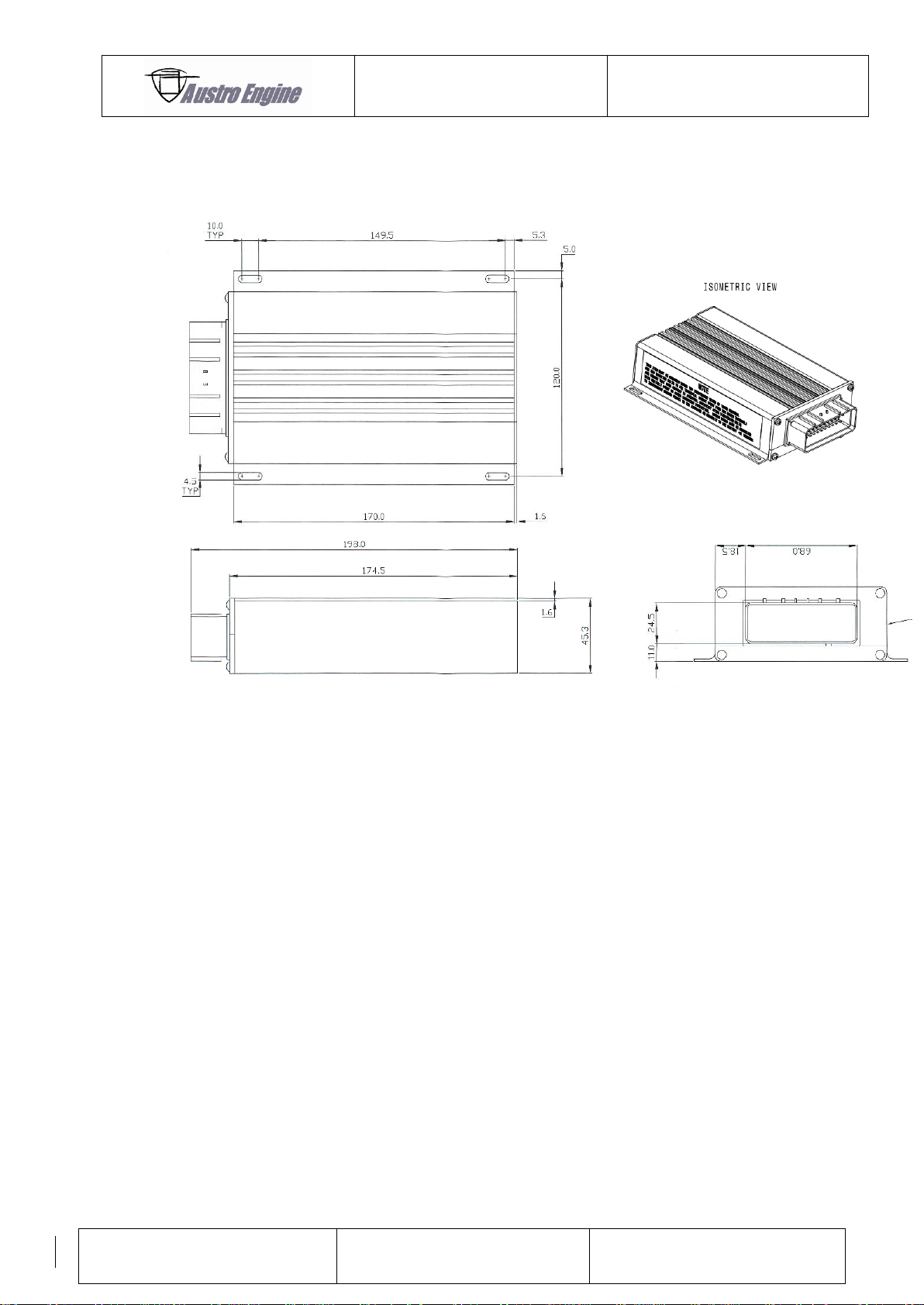
ENGINE MANUAL
IAE50R – AA
E1.01.05 – E
Issue date: 25.Jan.2018
Page: 19-3
Revision no: 9
19.1.3 Mechanical installation of the ECU
It is suggested to install the ECU outside of a dedicated fire zone.
Fig. 12: Mechanical installation of the ECU
Fig. 13 ECU Dimensions (in mm)
Mounting of the ECU is possible via 4 elongated holes. M4 screws with washers on the side
of the ECU housing are suggested.
The ECU must be grounded using two independent wires of 16AWG minimum. The
mounting bolts can be used to fix terminals. Remove paint from box under terminals and
ensure that good contact is achieved. Reprotect after tightening bolts with suitable paint or
other corrosion protection. Ground wires must be connected to independent ground points
on the airframe or directly to the battery GND Terminal
Page 64
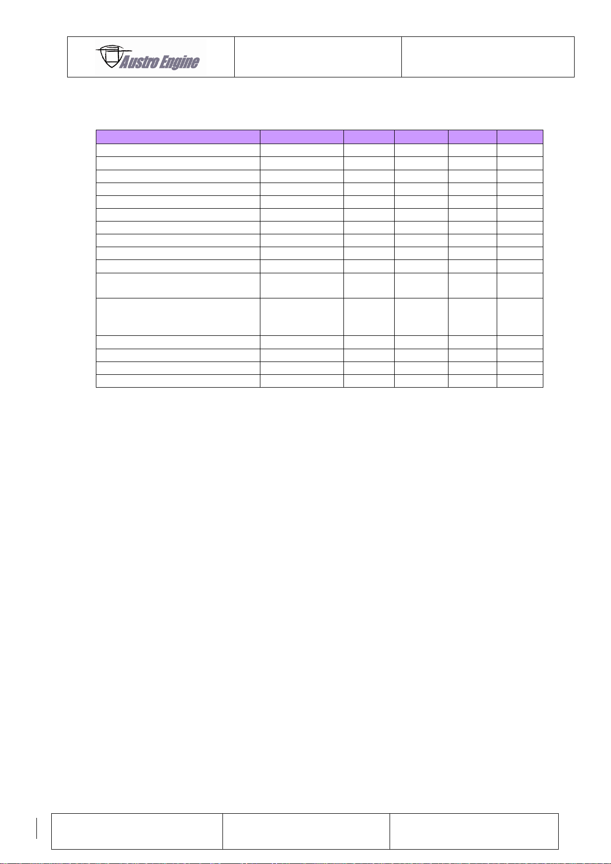
ENGINE MANUAL
IAE50R – AA
E1.01.05 – E
Issue date: 25.Jan.2018
Page: 19-4
Revision no: 9
Description
Condition
Min
Typ
Max
Unit
Power Supply
--- 9 12
14.8
V
Power supply current ECU *)
---
---
---
500
mA
Power supply current System **)
3000 rpm
---
--- 2 A
GND connection ECU
---
---
---
100
mOhm
C-Meter Low side switch
---
---
--- 1 A
C-Meter Low side switch
---
---
--- 5 V
P-Meter Low side switch
---
---
--- 1 A
P-Meter Low side switch
---
---
--- 5 V
F-Meter Low side switch
---
---
--- 1 A
F-Meter Low side switch
---
---
--- 5 V
Tacho Low side switch
Pull-up 2k2 to Ubatt
---
---
--- 1 A
TX Low side switch
(Error Lamp)
Pull-up 2k2 to Ubatt
---
---
--- 1 A
RX
---
---
---
Ubatt
V
CAN Bus Termination
---
---
120
---
Ohm
CAN Bus Baud Rate
---
---
500
---
kBaud
Instrument +5V
---
---
--- 2 mA
19.1.4 Electrical installation of the ECU
*) The suggested circuit breaker for each supply line 1 amp circuit breaker (2 x 1 amp
circuit breakers)
**) System consists of ECU, Sensors and Actuators
Page 65
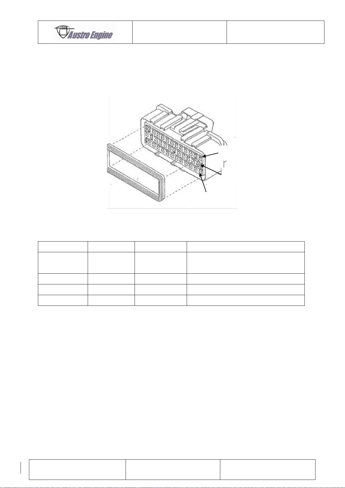
ENGINE MANUAL
IAE50R – AA
E1.01.05 – E
Issue date: 25.Jan.2018
Page: 19-5
Revision no: 9
Description
Manufacturer
Part Number
Manufacturer Description
ECU Harness
Connector
TE
344111-1
36WAY Receptacle Housing Connector
Wire Seal
TE
347874-1
Wire Seal AWG16 - AWG20
Anti Backout
TE
344112-1
Anti Backout
Crimp
TE
344113-1
Crimp AWG14 – AWG20
A1
B1
C1
19.1.4.1 Harness Connector for ECU
The picture and the table below shall give installer information which type of connector and
accessories are suitable for engine harness manufacturing.
The connector and accessories described in this section are not part of Austro Engine delivery.
Fig. 14: ECU harness connector
Table 1
Page 66
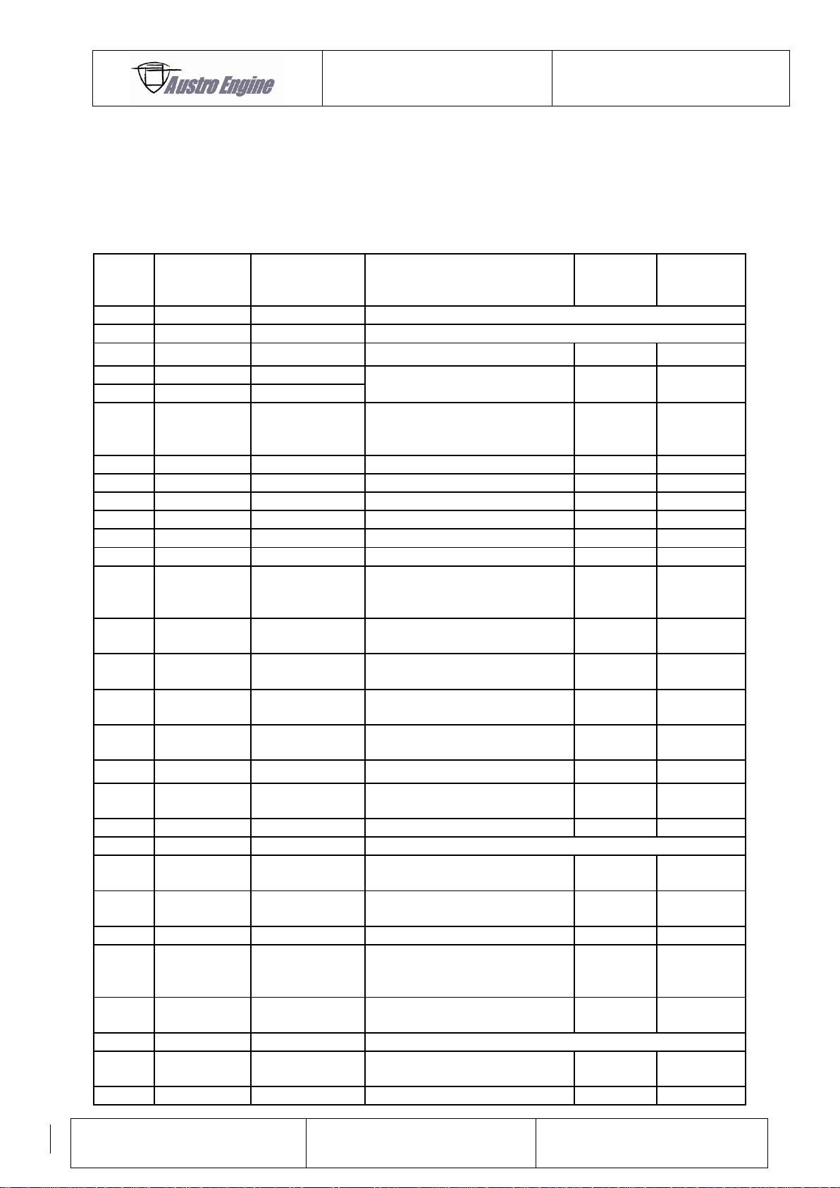
ENGINE MANUAL
IAE50R – AA
E1.01.05 – E
Issue date: 25.Jan.2018
Page: 19-6
Revision no: 9
ECU
PIN
Description
Signal Type
Description
Shielding
Cable
Diameter
(Minimum)
A1
Injector 2
Low Side Switch
not used for IAE50R-AA
A2
Ins Drive 3
Low Side Switch
not used for IAE50R-AA
A3
MAP 1 Signal
Input Signal
Yes
AWG 20
A4
CAN A
High
only for diagnostic
Yes
AWG 20
A6
CAN A
Low
A5
MAP1, RCA &
Intake Air
Temp GND
GND
Sensor GND
No
AWG 20
A7
GND
GND
ECU GND
No
AWG 16
A8
GND
GND
ECU GND
No
AWG 16
A9
ECU Power
UBAT
ECU Supply
No
AWG18
A10
ECU Power
UBAT
ECU Supply
No
AWG18
A11
Ins Drive 1
Low Side Switch
Coolant Signal Out
No
AWG18
A12
Injector 1
Low Side Switch
Injector 1
No
AWG 20
B1
TX
Low Side Switch
2k2 Pull Up to
UBAT
Error Lamp Out
No
AWG 20
C5
RX
Serial Input incl.
Inverter
Communication
No
AWG 20
B2
Pickup 2 PWR
12V Sensor
Supply
Sensor Supply
Yes
AWG 20
B3
Pickup 1 PWR
12V Sensor
Supply
Sensor Supply
Yes
AWG 20
B4
Intake Air
Temp Signal
Input Signal
Sensor Signal
No
AWG 20
B5
Map 2 Signal
Input Signal
Sensor Signal
Yes
AWG 20
B6
Map 1 Power
5V Sensor
Supply
Sensor Supply
Yes
AWG 20
B7
Map 2 GND
GND
Sensor GND
Yes
AWG 20
B8
CAN B
High
not used for IAE50R-AA
B9
Pickup 2
Signal
Input Signal
Sensor Signal
Yes
AWG 20
B10
T3I
Digital Input 2k2
Pull Up to 5V
Instrument +5V
No
AWG 20
B11
Tacho Drive
Low Side Switch
Engine speed Out
No
AWG 20
B12
Ins Drive 2
Low Side Switch
2k2 Pull Up to
UBAT
Fuel Consumption Out
No
AWG 18
C1
Ignition Coil
A (-)
Low Side Switch
Ignition
No
AWG 16
C2
Spare
Low Side Switch
not used for IAE50R-AA
C3
Map 2 PWR
5V Sensor
Supply
Sensor Supply
Yes
AWG 20
C4
Pickup 2 GND
GND
Sensor GND
Yes
AWG 20
19.1.4.2 ECU Pin Assignment
The table below gives information for installers how to connect ECU to sensor / actuators. It is
not allowed to use other diameters for electrical installation than minimum required by Austro
Engine.
Only Austro Engine qualified sensors and actuators are allowed to be used with ECU.
Page 67
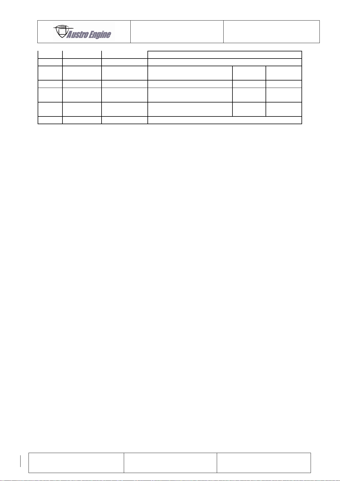
ENGINE MANUAL
IAE50R – AA
E1.01.05 – E
Issue date: 25.Jan.2018
Page: 19-7
Revision no: 9
C6
CAN B
Low
not used for IAE50R-AA
C7
CAN 3
not used for IAE50R-AA
C8
Rotor Air Out
Temp Signal
Input Signal
Sensor Signal
No
AWG 20
C9
Pickup 1 GND
GND
Sensor GND
Yes
AWG 20
C10
Pickup 1
Signal
Input Signal
Sensor Signal
Yes
AWG 20
C11
Ignition Coil
B (-)
Low Side Switch
Ignition
No
AWG 16
C12
Spare
Low Side Switch
not used for IAE50R-AA
Page 68
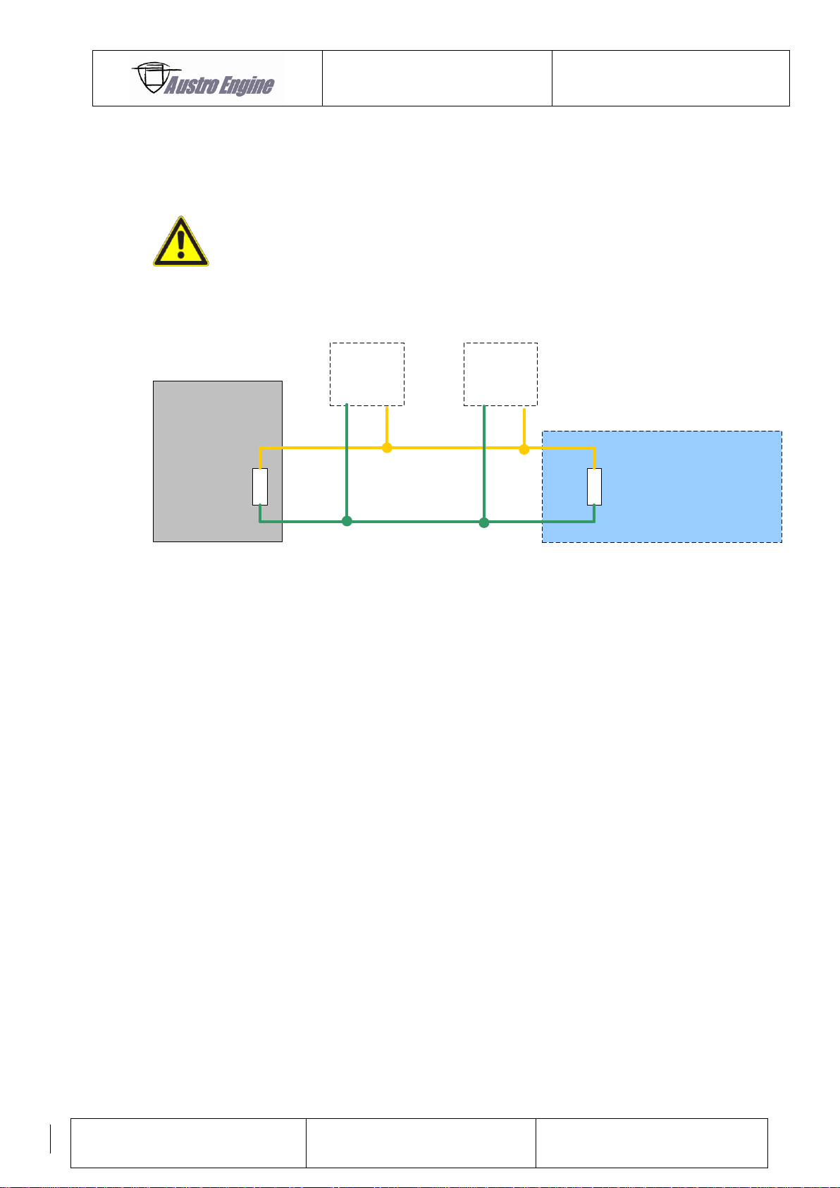
ENGINE MANUAL
IAE50R – AA
E1.01.05 – E
Issue date: 25.Jan.2018
Page: 19-8
Revision no: 9
CAN Termination in
Installation
120R
EECU
120R
CAN
nodes
CAN
nodes
CAN Low
CAN High
CAN
termination
19.1.4.3 CAN Bus
The diagnostic interface is a High Speed CAN Bus (with 500k Baud) which is used to transmit
all information to a CAN node.
A BUS termination is required at the physical end of the BUS.
For Example:
CAN-termination resistors 60R (2x 120R in parallel, 120R in EECU
included)
(CAN Bus according ISO 11898)
Fig. 15: CAN Bus termination
According to the CAN BUS Protocol each ECU sends its own engine information.
For details of the protocol contact Austro Engine GmbH.
Page 69
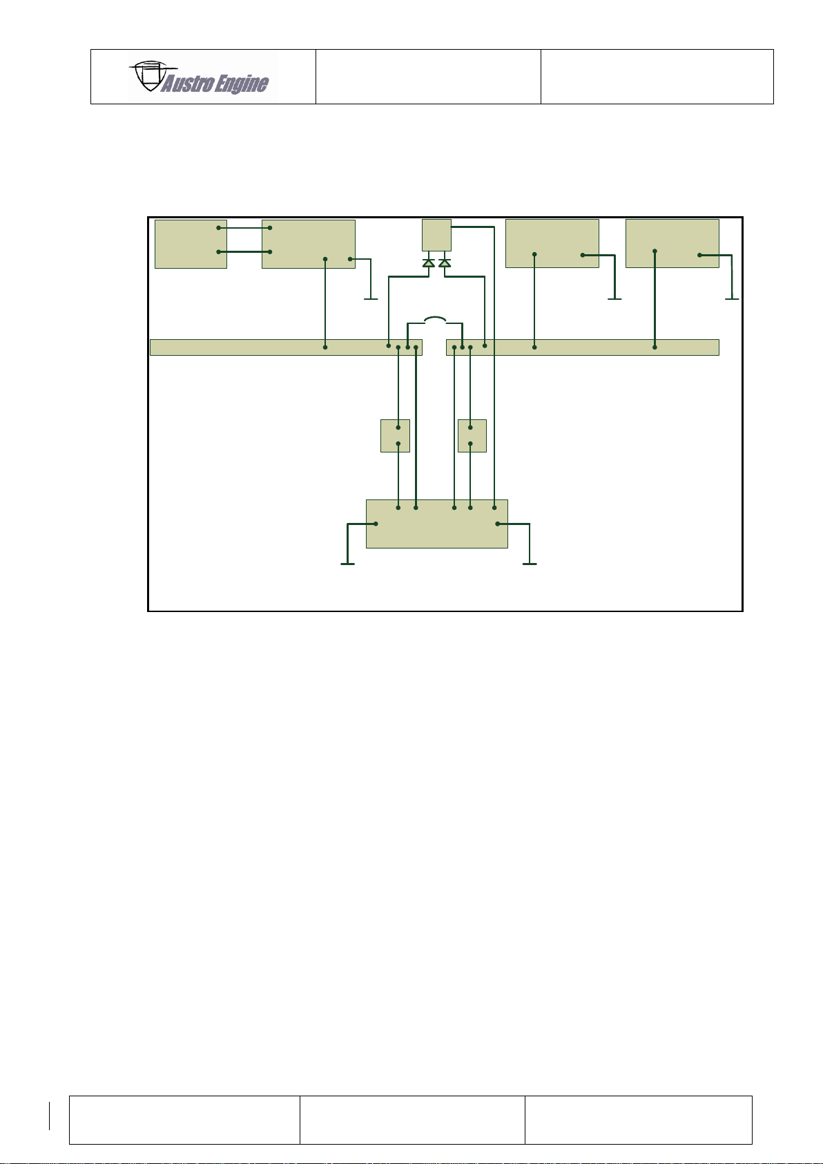
ENGINE MANUAL
IAE50R – AA
E1.01.05 – E
Issue date: 25.Jan.2018
Page: 19-9
Revision no: 9
12V Generator Bus 12V Battery Bus
12V Battery
ECU
Starter
Generator Generator Regulator
Bus Tie Max
25Amp
+ +- -
+
-
IGN1A IGN2A
INJ1
Basic Recommended Installation of ECU Supply Bus to fulfill
Do160 Sec.16 CAT Z
19.1.4.4 Option: Installation of ECU according D0160 section 16 CAT Z
If installation according DO160C section 16 CAT Z is required an independent power supply is
required. Suggestion for such installation is shown in the following figure:
Fig. 16: Cat Z
To meet category Z as tested in certification progress you have to ensure that the ECU is
supplied directly from alternator and battery with two separate lines. The installation shall
ensure power supply to ECU in case of fault of alternator or battery.
The proposal of wiring principal is shown in the figure above. These protect against a short to
ground in the supply wires to the ECU, preventing high current drain from the ECU internal
bus bar from the other supply which would cause the ungrounded breaker to “pop”.
For further information contact Austro Engine GmbH.
Page 70
ENGINE MANUAL
IAE50R – AA
E1.01.05 – E
Issue date: 25.Jan.2018
Page: 19-10
Revision no: 9
Description
Condition
Power
Unit
Voltage
Unit
Error Lamp (suggested)
--- 3 W
12
V
19.1.4.5 Error Codes
When the engine is stopped and fault–free, the ECU output B1 (TX) will be on continuously
switched to UBAT whilst the ECU is powered.
When the engine is running and fault–free, the output B1 (TX) will be switched to GND.
When an error is detected by the ECU unit, due either to a sensor failure, an out-of-range
indication or an internal unit fault, the ECU output B1 (TX) will give an indication of the
failure. Error warning display is continuously lit during engine operation. When the engine is
stopped, and there are errors, the ECU output B1 (TX) will flash with a coded message to
indicate which fault has occurred whilst the ECU is powered. Each error code consists of two
numbers. These are indicated via flashes in two groups (E.g. the code for 2 3: ECU output B1
(TX) will flash twice – then on steady for one second – and then flash three times).
If there is more than one error then each code will be flashed in sequence with 5 seconds
between codes.
The error lamp must be provided by the installer if required.
Page 71
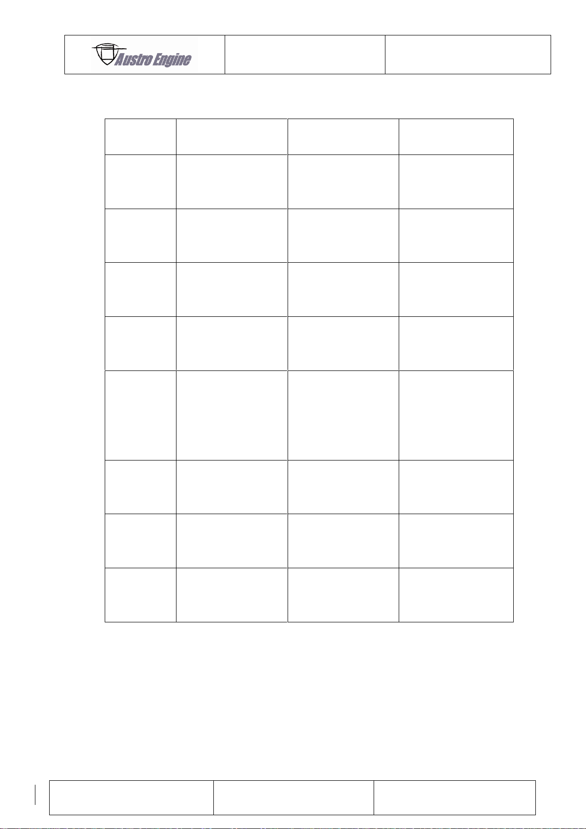
ENGINE MANUAL
IAE50R – AA
E1.01.05 – E
Issue date: 25.Jan.2018
Page: 19-11
Revision no: 9
CODE
FAILURE ITEM
DESCRIPTION
ACTION BY PILOT
DURING FLIGHT
1 1
Manifold Press 1
Sensor
Sensor faulty
Not connected –
Out of range
None
Investigate after
landing
1 2
Manifold Press 2
Sensor
Sensor faulty
Not connected –
Out of range
None
Investigate after
landing
1 3
Air Temperature
Sensor
Sensor short circuit or
sensor low
None
Investigate after
landing
1 4
Rotor Cooling Air
Sensor
Sensor open circuit or
reading high
None
Investigate after
landing
2 1
Supply Voltage
Supply volts decrease
Switch off non–
essential electrical
devices -> then
investigate after
landing
2 2
Engine Speed 1
Error or electronic
noise has been
detected
None
Investigate after
landing
2 3
Engine Speed 2
Error or electronic
noise has been
detected
None
Investigate after
landing
3 2
Manifold Air Pressure
Difference
Difference between
MAP 1 and MAP 2
sensor too high
None
Investigate after
landing
19.1.4.6 Error Code Table
Page 72
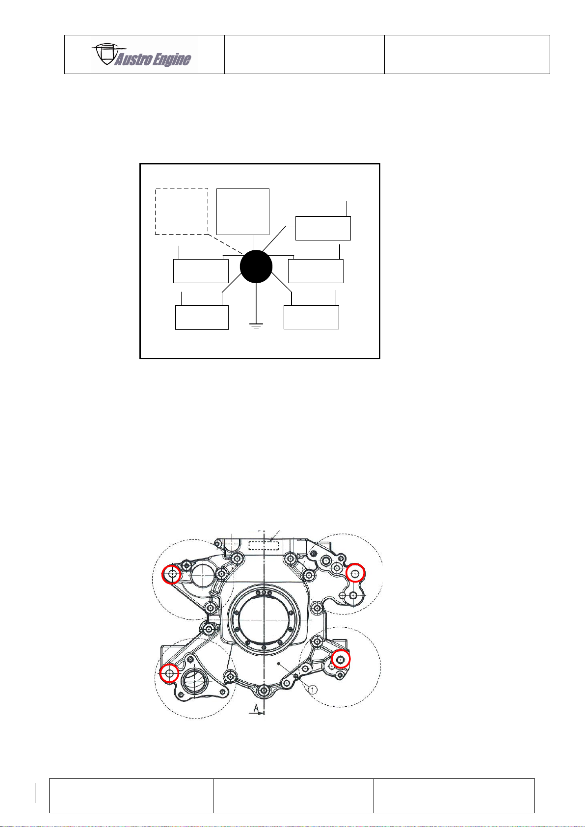
ENGINE MANUAL
IAE50R – AA
E1.01.05 – E
Issue date: 25.Jan.2018
Page: 19-12
Revision no: 9
Engine
housing
12V Battery
Capacitor
+
-
Generator
Regulator
+-
+ -
Aircraft
GND
ECU
+-
Starter
+
-
19.2 GND Concept IAE50R
A common Ground (GND) concept is required for the installation of the IAE50R. This means all
electrical GND are connected together. Best practice is a star layout, which can be seen in the
following figure. The aircraft GND shall be included.
Fig. 17: GND concept
Possible GND connection Points
) Regulator see Chapter Generator Regulator
) Engine: Possible connecting points for the engine GND
Engine backplate see Fig. 18
Screw for starter motor mounting
For any other points on the engine contact Austro Engine GmbH
Max allowed contact resistance for engine GND connection 50 mOhm
Wire suggestion 4x AWG14 GND; Engine housing to Battery negative terminal.
Fig. 18: Engine GND
Page 73
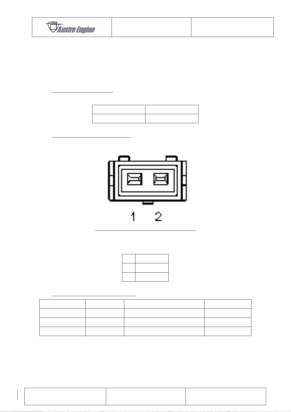
ENGINE MANUAL
IAE50R – AA
E1.01.05 – E
Issue date: 25.Jan.2018
Page: 19-13
Revision no: 9
Part Number
QTY per engine
E4A-40-000-804
1
Pin
Description
1
GND
2
Signal
Description
Manufacturer
Part Number
QTY (per sensor)
Seal
Bosch
1 987 280 106 / 1 987 280 107
2
Crimp
Bosch
1 987 280 103 / 1987 280 105
2
Connector Housing
Bosch
1 237 000 036
1
19.3 Sensors and actuators
19.3.1 Air Temperature sensor
The sensor should be installed with its probe in the induction airflow.
Type of Air Temp Sensor(s):
Pin Assignment Air Temp Sensor(s):
Fig. 19
Mating Connector for Air Temp Sensor:
Page 74
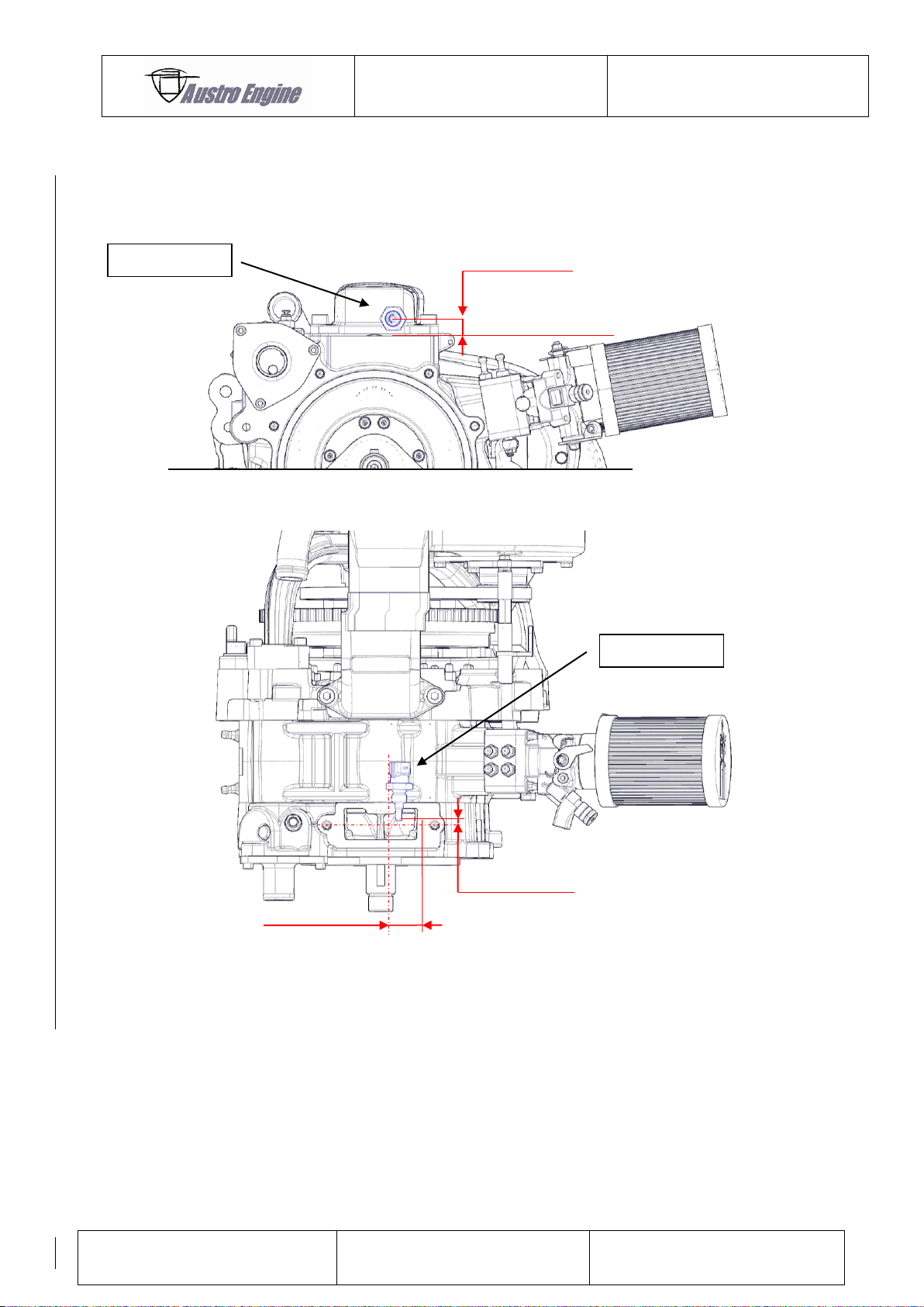
ENGINE MANUAL
IAE50R – AA
E1.01.05 – E
Issue date: 25.Jan.2018
Page: 19-14
Revision no: 9
approx. 10 mm
approx. 5,3 mm
approx. 27 mm
RCAO flange surface
Temp.
Temp.
19.3.2 Rotor cooling air out temperature sensor
The sensor should be mounted as defined in the following figures:
Fig. 20
Page 75
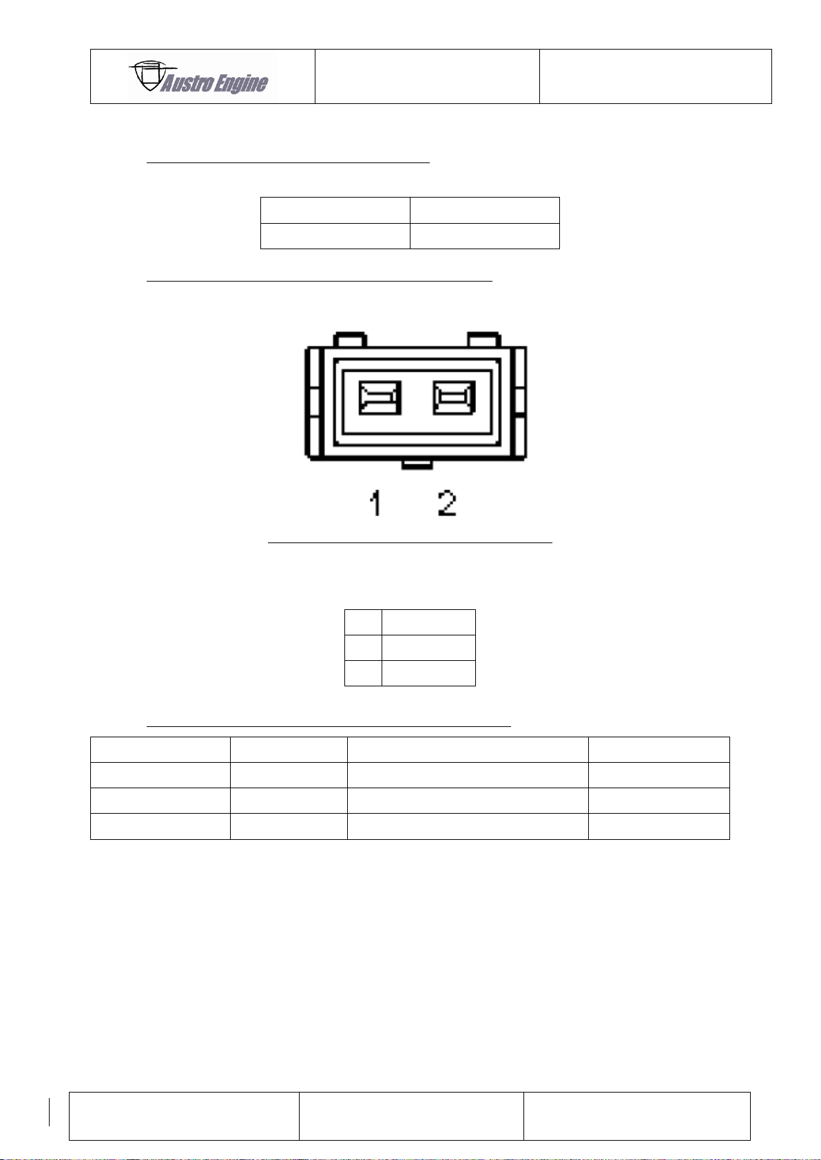
ENGINE MANUAL
IAE50R – AA
E1.01.05 – E
Issue date: 25.Jan.2018
Page: 19-15
Revision no: 9
Part Number
QTY per engine
E4A-40-000-804
1
Pin
Description
1
Signal
2
GND
Description
Manufacturer
Part Number
QTY (per sensor)
Seal
Bosch
1 987 280 106 / 1 987 280 107
2
Crimp
Bosch
1 987 280 103 / 1987 280 105
2
Connector Housing
Bosch
1 237 000 036
1
Type of Rotor Cooling Air out Temp Sensor(s):
Pin Assignment of Rotor Cooling Air out Temp Sensor(s):
Fig. 21
Mating Connector for of Rotor Cooling Air out Temp Sensor:
Page 76
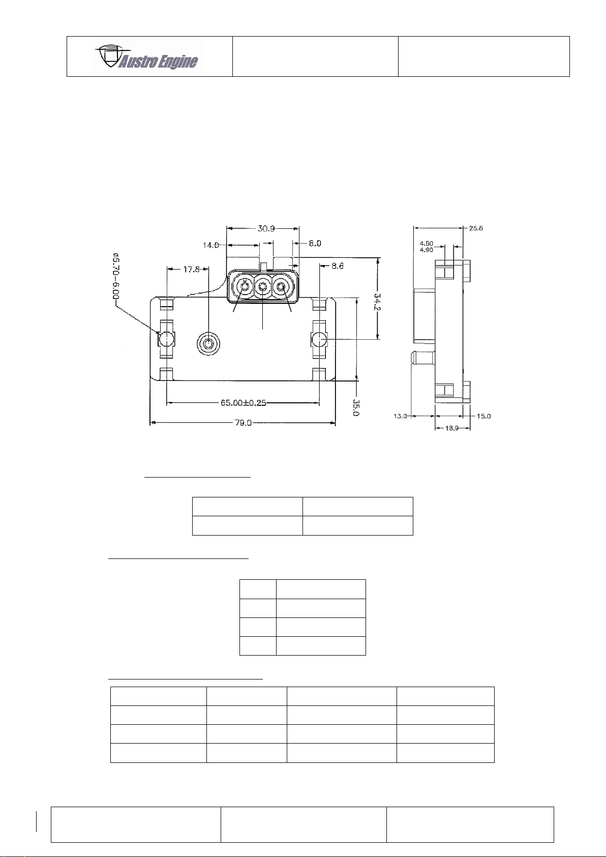
ENGINE MANUAL
IAE50R – AA
E1.01.05 – E
Issue date: 25.Jan.2018
Page: 19-16
Revision no: 9
VCC
VOUT
GND
Part Number
QTY per engine
R1A-09-100-000
2
Pin
Description
VCC
5V Sensor Supply
VOUT
Output Signal
GND
Ground
Description
Manufacturer
Part Number
QTY (per sensor)
Seal
Delphi
12015899 / 15324983
3
Crimp
Delphi
12089040-L
3
Connector Housing
Delphi
12015793
1
19.3.3 Map Sensors
The sensor must be mounted by the installer with the pressure inlet at the bottom and the
flexible pipes running down the throttle body spacer, thus allowing any fuel in the pipe to
drain back into the engine.
The flexible pipe (Inner-Diameter 6mm) must be at least oil resistant (fuel, engine oil) and
does not change the inner diameter at inlet pressures of 20kPa.
Fig. 22
Type of MAP Sensor(s):
Pin Assignment MAP Sensor(s):
Mating Connector for MAP Sensor:
Page 77
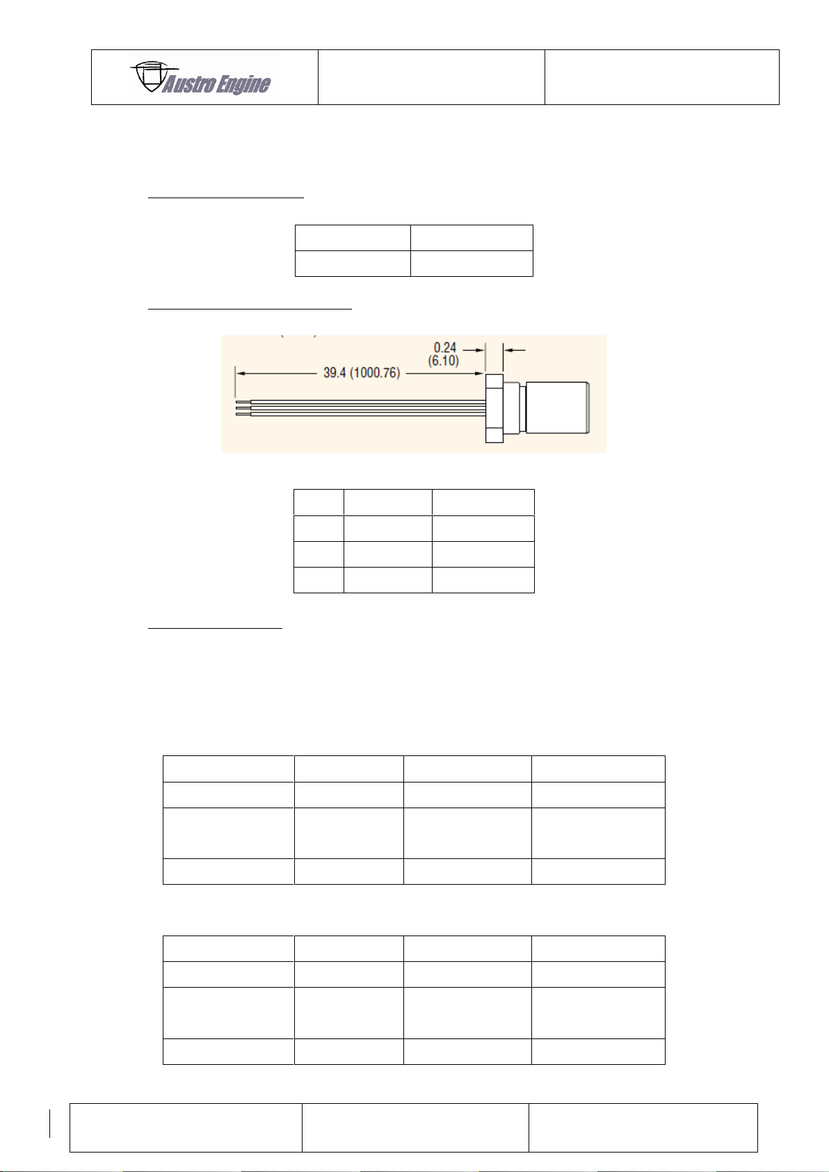
ENGINE MANUAL
IAE50R – AA
E1.01.05 – E
Issue date: 25.Jan.2018
Page: 19-17
Revision no: 9
Part Number
QTY per engine
R1A-09-000-802
2
Pin
Wire Color
Description
VCC
Brown
Sensor Supply
VOUT
Black
Output Signal
GND
Blue
GND
Description
Manufacturer
Part Number
QTY (per sensor)
Seal
Tyco / TE
281934-4
3
Crimp
Tyco / TE
AWG20: 183024-1
AWG22: 183036-1
3
Connector Housing
Tyco / TE
282105-1
1
Description
Manufacturer
Part Number
QTY (per sensor)
Seal
Tyco / TE
281934-4
3
Crimp
Tyco / TE
AWG22: 183035-1
AWG20: 282404-1
3
Connector Housing
Tyco / TE
282087-1
1
19.3.4 Speed Sensors
Mounting provisions are given on the engine.
Type of Speed Sensor(s):
Pin Assignment Speed Sensor(s):
Fig. 23
Connector for Sensor:
Sensor is supplied with open wires. It is recommended to use dust and water protected
connectors for engine harness adaption. An adequate connector type can be found in the
following tables.
Possible Sensor connector:
Possible Mating connector:
Page 78
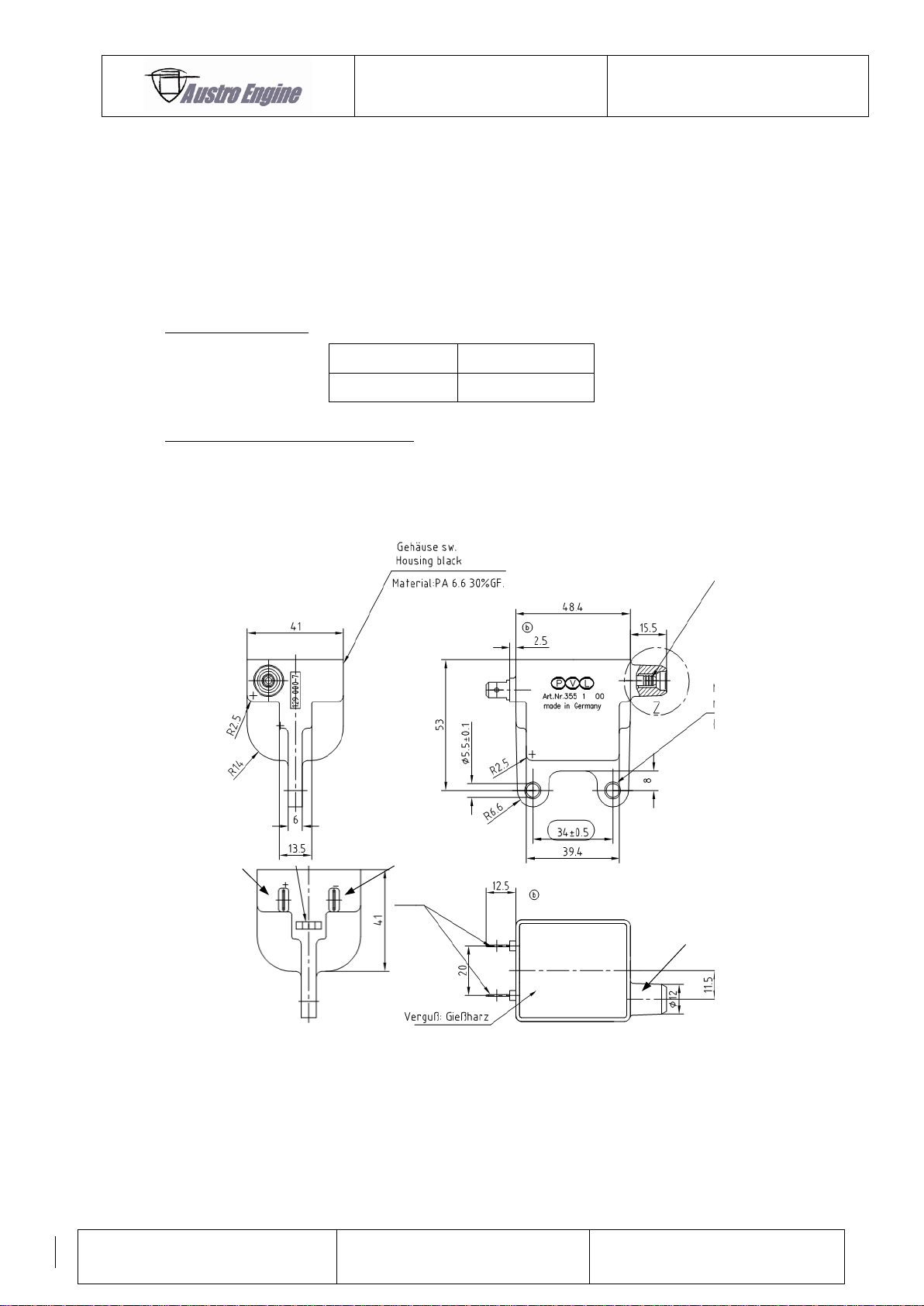
ENGINE MANUAL
IAE50R – AA
E1.01.05 – E
Issue date: 25.Jan.2018
Page: 19-18
Revision no: 9
Part Number
QTY per engine
R1A-09-000-804
2
Pin Assignment Ignition Coil:
Fig. 4
Fig. 5
Negative
To spark plug
Positive
19.3.5 Ignition Coils
It hast to be mentioned that the ignition coils are close enough to spark plugs
(Note the maximum length of ignition cable R1A-09-000-501 -> 200 mm)
Power supply ignition coil: The installer should provide independent switches to interrupt the
power supply for each ignition coil separately if required.
Type of Ignition Coil:
Mechanical and electrical connection
For the mechanical mounting of the coils two M5 screws with washers should be used.
Connect the power supply for the coil on the positive terminal and the ECU-signal on negative
terminal of the coil.
Fig. 24: Ignition coil
Page 79
ENGINE MANUAL
IAE50R – AA
E1.01.05 – E
Issue date: 25.Jan.2018
Page: 19-19
Revision no: 9
Pin
Connector
Description
Positive
Plain Connector 6.3mm
DIN 46 244
Ubatt
Negative
Plain Connector 6.3mm
DIN 46 244
Signal from ECU
Spark Plug
R1A-09-000-501
Connection to Spark Plug
Part Number
QTY per engine
R1A-09-000-501
2
19.3.5.1 H.T. Leads
The inductive H.T. coils are connected to the spark plugs by copper–cored cable and resistive
plug caps. The cable is provided by AE.
19.3.5.2 Spark plugs
The specified spark plug type must be used; substitution with a non–approved type may
reduce engine power and reliability, and may cause mechanical damage to the engine.
Page 80
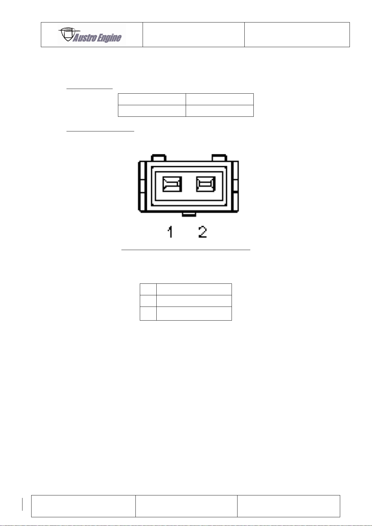
ENGINE MANUAL
IAE50R – AA
E1.01.05 – E
Issue date: 25.Jan.2018
Page: 19-20
Revision no: 9
Part Number
QTY per engine
R1A-30-000-801
1
Pin
Description
1
ECU Signal
2
Injector Supply (+UBAT)
19.3.6 Injector
One injector is used for the IAE50R-AA Engine.
Type of Injector:
Pin Assignment Injector:
Fig. 25
Page 81
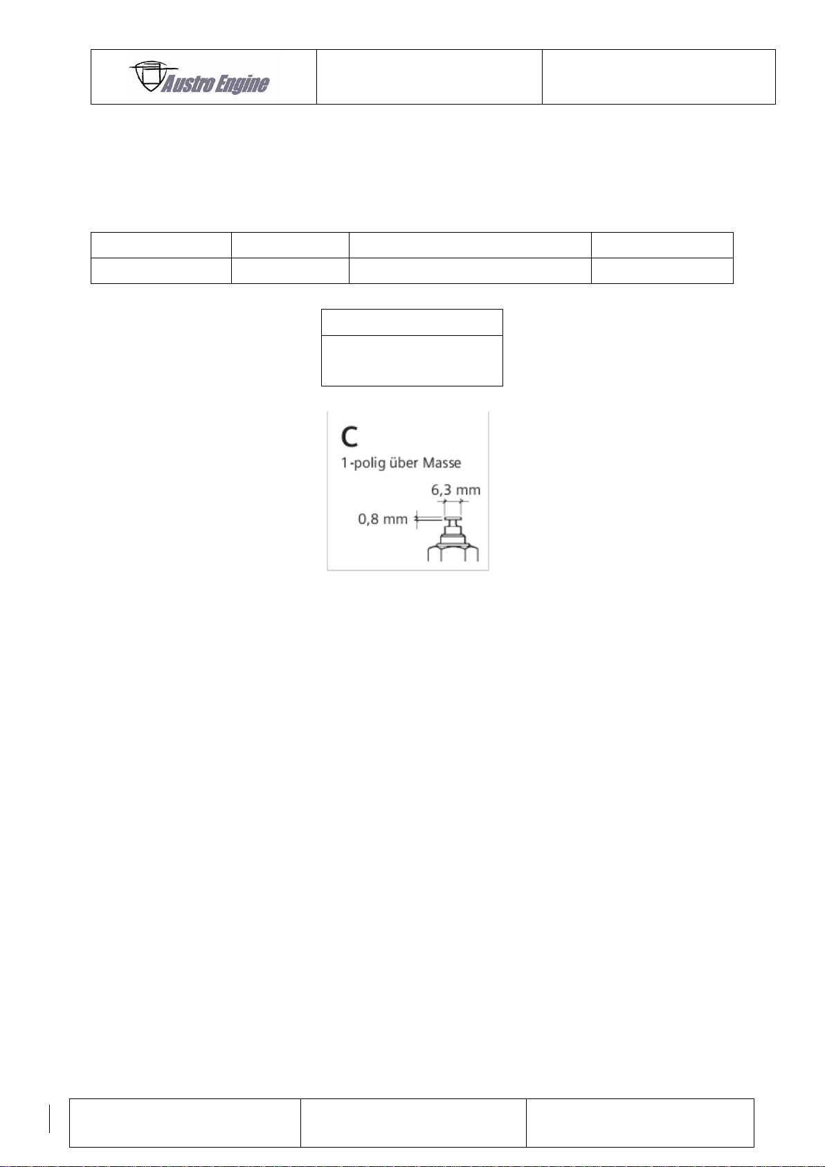
ENGINE MANUAL
IAE50R – AA
E1.01.05 – E
Issue date: 25.Jan.2018
Page: 19-21
Revision no: 9
Description
Manufacturer
Operating temp
Ohm @90°C
Thermistor
VDO
120°C
51,2 ±5,3
Connector
Plain Connector 6.3mm
DIN 46 244
19.3.7 Coolant Temperature Sensor for instruments
A temperature sensor R1A-10-000-803 is fitted to the engine in the front plate, for connecting
to a temperature gauge, or an external instrumentation panel.
This sensor is a provision for the installer. It is not connected to the ECU.
Fig. 26: Coolant temperature sensor
Page 82
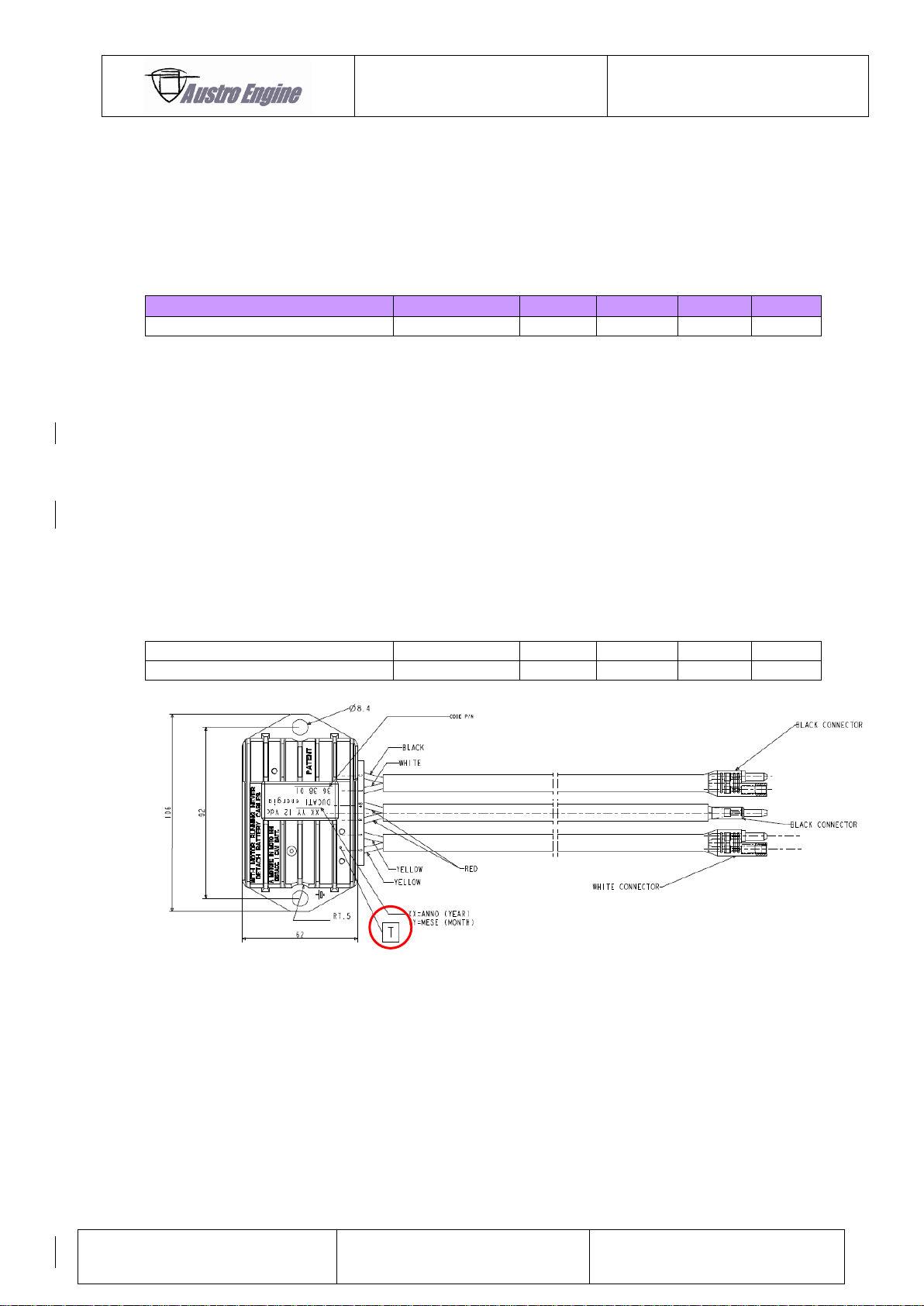
ENGINE MANUAL
IAE50R – AA
E1.01.05 – E
Issue date: 25.Jan.2018
Page: 19-22
Revision no: 9
Description
Condition
Min
Typ
Max
Unit
Power supply Current
---
---
18
---
A
Description
Condition
Min
Typ
Max
Unit
GND connection Gen. Regulator
---
---
---
50
mOhm
19.4 Generator regulator and Generator wiring
Generator regulator and generator are supplied by Austro Engine GmbH. The flywheel
mounted brushless / bearing less generator is mounted on the engine. The separate voltage
control regulator / rectifier unit must be connected and mounted by the installer.
19.4.1 Mechanical installation of the Generator Regulator
Mounting of the Regulator is possible via M8 screws on both sides of the Regulator.
Install the regulator on a well-ventilated place. The temperature on the regulator should never
exceed +80°C measured at point T shown in Fig. 27.
The housing of the regulator must be electrical connected to GND. Connect the GND directly
with the mounting bolts or with two independent wires (>AWG14 minimum). The mounting
bolts can be used to fix terminals.
Fig. 27: Regulator housing
Page 83
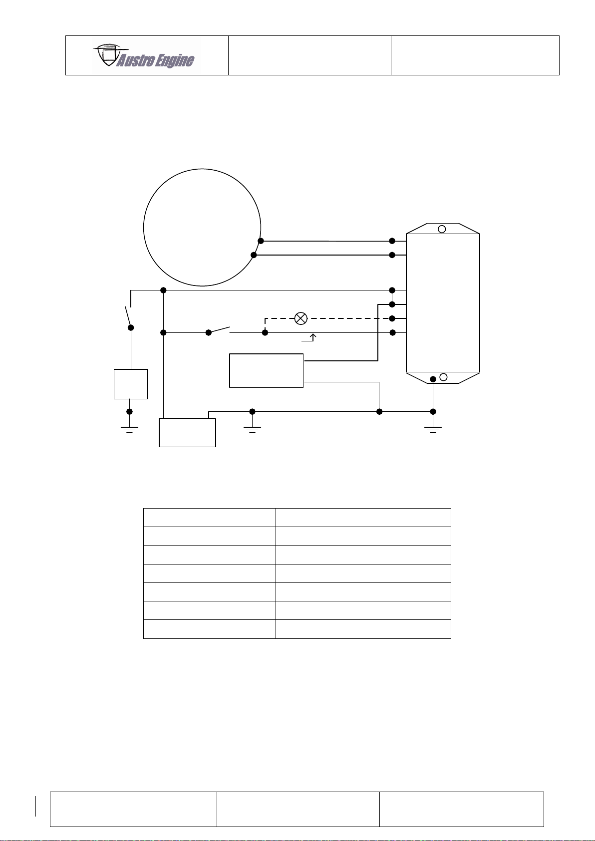
ENGINE MANUAL
IAE50R – AA
E1.01.05 – E
Issue date: 25.Jan.2018
Page: 19-23
Revision no: 9
GEN
BATT
12V
yellow
yellow
white
red
red
black
12V -3W
Not requsted
22000 µF
40-65V+-
> AWG 14
AWG 16
AWG 16
AWG 16
AWG 16
AWG 16
AWG 16
No Load on Black Terminal
Load
+ -
Regulator
Voltage Regulator Cable
Connected to:
Yellow
Yellow Cable Generator
Yellow
Yellow cable Generator
Red
Power (+12V)
Red
Power (+12V)
White
12V Lamp (Not requested)
Black
Power (+12V) Switchable (ON / OFF)
19.4.2 Electrical installation of the Regulator
The wiring for connecting the generator and generator regulator is described in following
figure:
Fig. 28: Wiring diagram Generator and Regulator
10.1.2 Charge Circuit Fail Alarm
The installer is responsible for a wiring which indicate a charge circuit failure alarm. In the
unlikely event of a charging circuit failure, indicated by the appropriate alarm, the electrical
bus bar will be fed automatically from the battery. Any non–essential electrical items should
be switched off.
The battery should be capable of providing sufficient power to run the ECU unit etc. for a
minimum of ½ hour. Reducing power will not significantly increase engine–running time.
Page 84
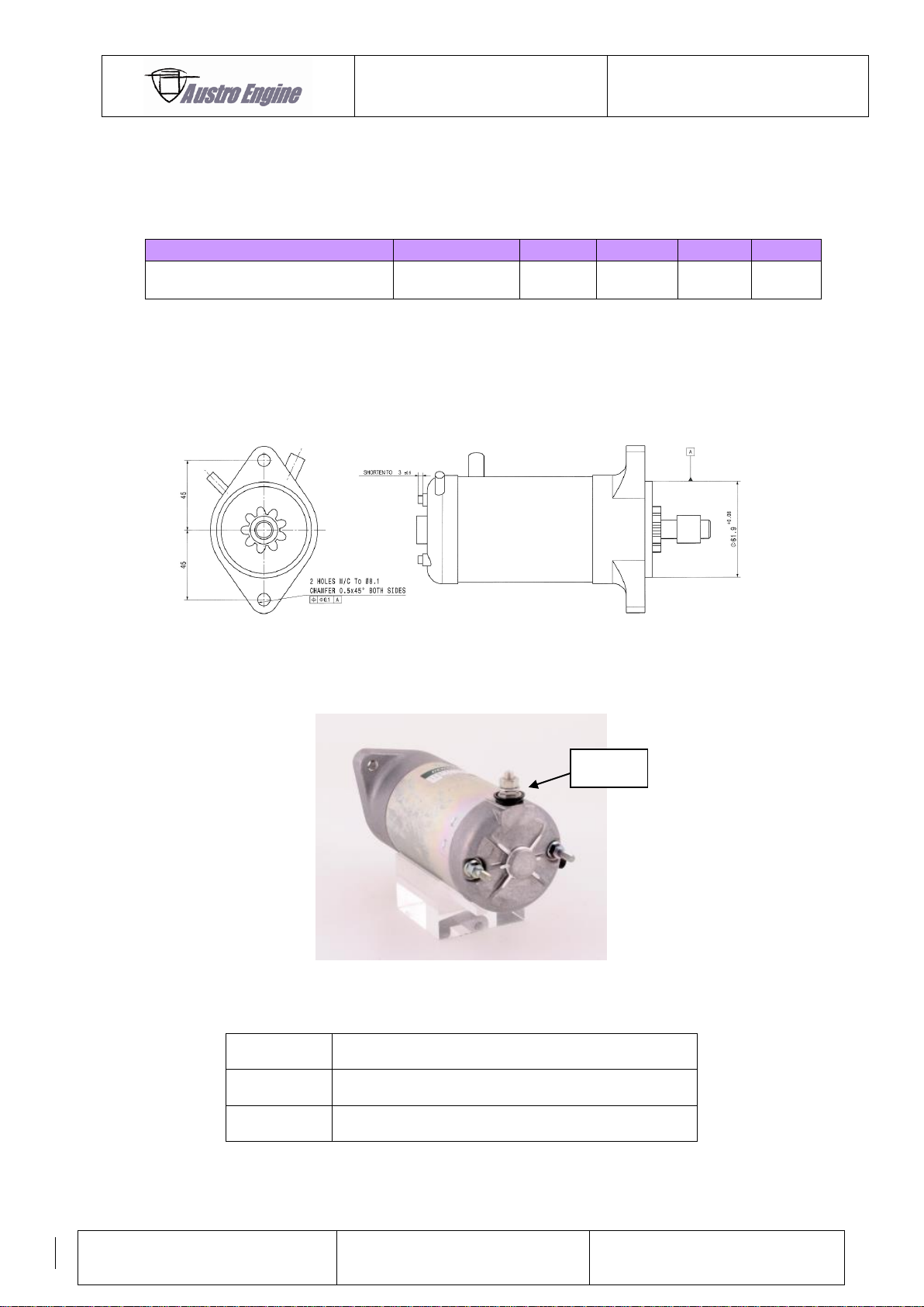
ENGINE MANUAL
IAE50R – AA
E1.01.05 – E
Issue date: 25.Jan.2018
Page: 19-24
Revision no: 9
Description
Condition
Min
Typ
Max
Unit
Start Current
(Battery 12,5V 18Ah)
---
---
80
---
A
Description
Electrical Connection
GND
Ground connection of starter via housing to engine
Bolt1
Switch able 12V starter actuation
Bolt 1
19.5 Starter
The starter R1A-90-000-000 is an electric nominal 12V / 0,6kW. It is of a Bendix Type,
engaging the gear when operated (refer to drawing no. R1A-90-000-000).
Voltage of Battery drops down during cranking. Inrush current can reach up to 350A for some
milliseconds.
19.5.1 Mechanical installation
The starter is mounted on the engine. Two M8 screws are used.
19.5.2
Fig. 29: Mechanical installation of the starter
Electrical connection of starter
Fig. 30: Starter
For fastening torque of bolt 1 see chapter 11.2.1.
.
Page 85
ENGINE MANUAL
IAE50R – AA
E1.01.05 – E
Issue date: 25.Jan.2018
Page: 19-25
Revision no: 9
19.6 Electronic Components Capability
The electronic components have been tested to meet environmental requirements as
specified in RTCA 160 C/D. The following information is to assist the engine installer.
To show that the ECU is not susceptible to failure when exposed to external electrical or
environmental effects, a number of tests were performed.
19.6.1 Electrical tests
Power Input Test DO-160C, Section 16 Cat Z.
The two power supply lines were connected to independent
power sources. One supply line was always powered.
Voltage Spike Test DO-160C, Section 17 Cat A.
Audio Frequency Conducted Susceptibility DO-160C, Section 18 Cat Z.
Induced Signal Susceptibility Test DO-160C, Section 19 Cat Z.
Conducted RF Susceptibility Test DO-160D, Section 20.4 Cat Y
Radiated RF Susceptibility Test DO-160C/D, Section 20.5 Cat Y
Emission of Radio Frequency Energy Conducted DO-160C, Section 21.4
Cable Bundl to ECU Cat Z and A
Power Lines to ECU Narrowband Cat Z and A
Broadband Cat B
Broadband not required in
Do-160D
Emission of Radio Frequency Energy Radiated DO-160C, Section 21.5
Lightening Induced Transient Susceptibility DO-160C, Section 22 Cat Z3
Magnetic Effect DO-160C, Section 15,
The compass safe distance for 1° deflection was established as:
0° at 5cm (EUT X-axis)
0,5° at 8cm (EUT Y-axis)
0,5° at 10cm (EUT Z-axis)
Cat A, B and Z
Equipment Class Z
Page 86
ENGINE MANUAL
IAE50R – AA
E1.01.05 – E
Issue date: 25.Jan.2018
Page: 19-26
Revision no: 9
19.6.2 Environmental tests
Operation Shock & Crash Safety Tests. DO-160D, Section 7. Category B
Sinusoidal Vibration Tests. DO-160D, Section 8 Cat. S
Curve M
Standard vibration test
fixed wing aircraft
Humidity Tests DO-160C; Section 6.3.2 Cat. B
Category B severed
humidity environment
65°C @ 95% humidity.
Waterproofness (Drip) Tests DO-160D, Section 10, Cat W,
falling water test
The ECU has been designed to operate between -15 °C and +70 °C. For the purposes of this
test, the ECU was operated at -45 °C and tested to -55 °C for ground survival (non –
operating).
Temperature & Altitude Tests DO-160C, Sections 4.5.1, 4.5.2,
4.5.3 and 4.6.1;
Cat B2
Temperature Variation Test DO-160C, Section 5 Cat B2
Fluids Susceptibility DO-160D, Section 11.*
The ECU and associated equipment is compatible with fluids liable to be found in
the vicinity of the engine.
The ECU and a sample of the cable loom complete with ident sleeve and tag were
subjected to the following fluids:
AVGAS 100LL, leaded and unleaded motor fuel, Jet A1 turbine fuel, “Comp-2” and
”SRG-75” lube oil, “Procool” coolant, “Aeroshell” fluids 31, 41 and “Skydrol 500B”
Hydraulic oils, Ethylene Glycol and “Kilfrost ABC-3” De-icing fluids, Isopropyl Alcohol,
Denatured Alcohol, and Trichoroethane solvents.
The ECU was not affected by the application of fluids.
The ECU was tested to determine its magnetic effect to assist the installer in choosing
the proper location of the equipment in the aircraft.
Page 87
ENGINE MANUAL
IAE50R – AA
E1.01.05 – E
Issue date: 25.Jan.2018
Page: 19-27
Revision no: 9
General information about D0160 tests.
Sensors and actuators are tested during basic certification with the test levels stated
above. For the requalification of the new AE ECU for the IAE50R the test levels from the
basic certification are assumed and applied dedicated to the ECU.
*DO-160D Section 11 was tested during the basic certification from Midwest Company.
19.6.3 Control System Reliability
19.6.3.1 Control system reliability objective.
Certification requirements states a reliability objective to be quoted in the engine manual.
The control system has been designed to meet AMJ20X–target reliability of 1 in 100,000 hours
when operated in accordance with Austro Engine GmbH stated maintenance and installation
specification.
19.6.3.2 Software Quality level
In accordance with DO 178B level C.
 Loading...