

Austria Email VT-N 1000-FFM, VT-N 800-FRM, VT-S 800-FFM, VT-S 1000-FFM, VT-N 1000-FRM Operating And Mounting Instructions Manual
...
Operating and Mounting Instructions
Pressure-proof large storage tank
of the series
Multi-purpose free-standing tank
VT-N 800-FFM, VT-N 1000-FFM
VT-S 800-FFM, VT-S 1000-FFM
High-performance free-standing coil tank
VT-N 800-FRM, VT-N 1000-FRM
VT-S 800-FRM, VT-S 1000-FRM
Multi-purpose free-standing coil tank
VT-N 800-FRMR, VT-N 1000-FRMR
VT-S 800-FRMR, VT-S 1000-FRMR
Please pass on to the user
* Technical changes and misprints reserved.
Technology
that makes you
feel good
Id.Nr.: 233754-4

Id.Nr.: 233754-4
Dear customer!
You have decided for water heating using a free-standing tank produced by our company.
We thank you for your trust.
You will receive an elegantly shaped device that was constructed in accordance with the state of the
art and the applicable regulations. The highly developed enamelling based on continuous research as
well as an ongoing quality control during the production provide our hot water tanks with technical
characteristics that you will always value. An extraordinarily low consumption of standby energy is
ensured by the environmentally friendly ECO Skin insulation. To the benefit of the environment, the
ARA licence of Austria Email AG allows you to dispose of you device’s packaging material in a suitable manner.
The installation and first commissioning must be performed by a licensed plumber and in accordance
with these instructions only.
You will find all important information for a correct assembly and operation in this small brochure.
Nevertheless, let your concessionary explain to you how the device functions and demonstrate its
operation. Naturally, our company is also gladly at your disposal to provide any advice.
Enjoy the use of your free-standing tank.
2

Id.Nr.: 233754-4
Table of Contents ................................................................Page
1. Hot Water Demand .............................................................................................................. 4
2. Energy Saving ......................................................................................................................4
3. Operating Requirements ..................................................................................................... 4
4. Service Water Connection ..................................................................................................5
5. Circuit Connection and Screw-mounted Heating .............................................................. 6
6. Flange Ports ........................................................................................................................6
7. Important Assembly Instruction .........................................................................................6
8. Corrosion Protection ........................................................................................................... 7
8.1 Series VT-N FFM ......................................................................................................... 7
8.2 Series VT-N FRM und FRMR ........................................................................................ 7
8.3 Series VT-S FRM und FRMR ......................................................................................... 8
9. Dimensioned Sketch ........................................................................................................... 9
9.1 E free-standing tank
VT-N 800-FFM, VT-N 1000-FFM
VT-S 800-FFM, VT-S 1000-FFM ................................................................................... 9
9.2 Multi-purpose free-standing tank
VT-N 800-FRM, VT-N 1000-FRM
VT-S 800-FRM, VT-S 1000-FRM.................................................................................. 10
9.3 High-performance free-standing coil tank
VT-N 800-FRMR, VT-N 1000-FRMR
VT-S 800-FRMR, VT-S 1000-FRMR ............................................................................. 11
10. Temperature Display, Temperature Control for Charge Pumps ...................................... 12
11. First Commissioning ........................................................................................................12
12. Decommissioning, Emptying ........................................................................................... 12
13. Check, Maintenance, Care ............................................................................................... 13
14. Warranty and Guarantee .................................................................................................. 14
3

Id.Nr.: 233754-4
1. Hot Water Demand
The hot water demand in a household depends on the number of persons, the sanitary installations of the
apartment or the house, and the individual habits of the user.
The following table provides a few standard values regarding consumption figures.
Hot Water Demand
in litres
with 37 °C with 55 °C with 80 °C with 60 °C
Full bath 150 - 180 55 - 66 78 - 94
Shower 30 - 50 11 - 18 16 - 26
Washing hands 3 - 6 1 - 2 1,6 - 3,1
Hair wash (short hair) 6 - 12 3 - 4,4 4,2 - 6,3
Hair wash (long hair) 10 - 18 3,7 - 6,6 5,2 - 9,4
Use of bidet 12 - 15 4,4 - 5,5 6,3 - 7,8
Washing dishes
for 2 persons per day 16 10 14
for 3 persons per day 20 12,5 18
for 4 persons per day 24 15,2 21,5
House cleaning
per bucket of cleaning water
The temperature of the cold water required for mixing up to the specified hot water temperature was assumed as being at approx. 12°C.
10 6,3 9
Required tank water quan-
tity in litres
2. Energy Saving
As a result of the high-quality, environmentally friendly ECO Skin insulation, your multi-purpose free-standing
tank is a real energy saver.
Low tank water temperatures (not below 60°C) prove to be particularly economical. This helps to save energy
and reduces furring in the container. A circuit connection should be avoided as far as possible.
3. Operating Requirements
The tanks must be used exclusively in accordance with the conditions specified on the rating plate. Aside from
the legally approved national regulations and standards, the connecting requirements of the local power company and waterworks, as well as the Mounting Operating Instructions must be complied with.
The room in which the device is operated should remain free of frost. The device must be mounted at a location
that is reasonably to be expected, i.e. the device must be easily accessible in the case of any necessary maintenance or repairs. In the case of heavily calciferous water, we recommend the upstream integration of a customary antiliming device or a maximum operating temperature of approx. 65°C.
An appropriate quality of drinking water is required for proper operation. To avoid possible ingresses of particles,
we recommend the upstream integration of a water filter.
4
Id.Nr.: 233754-4
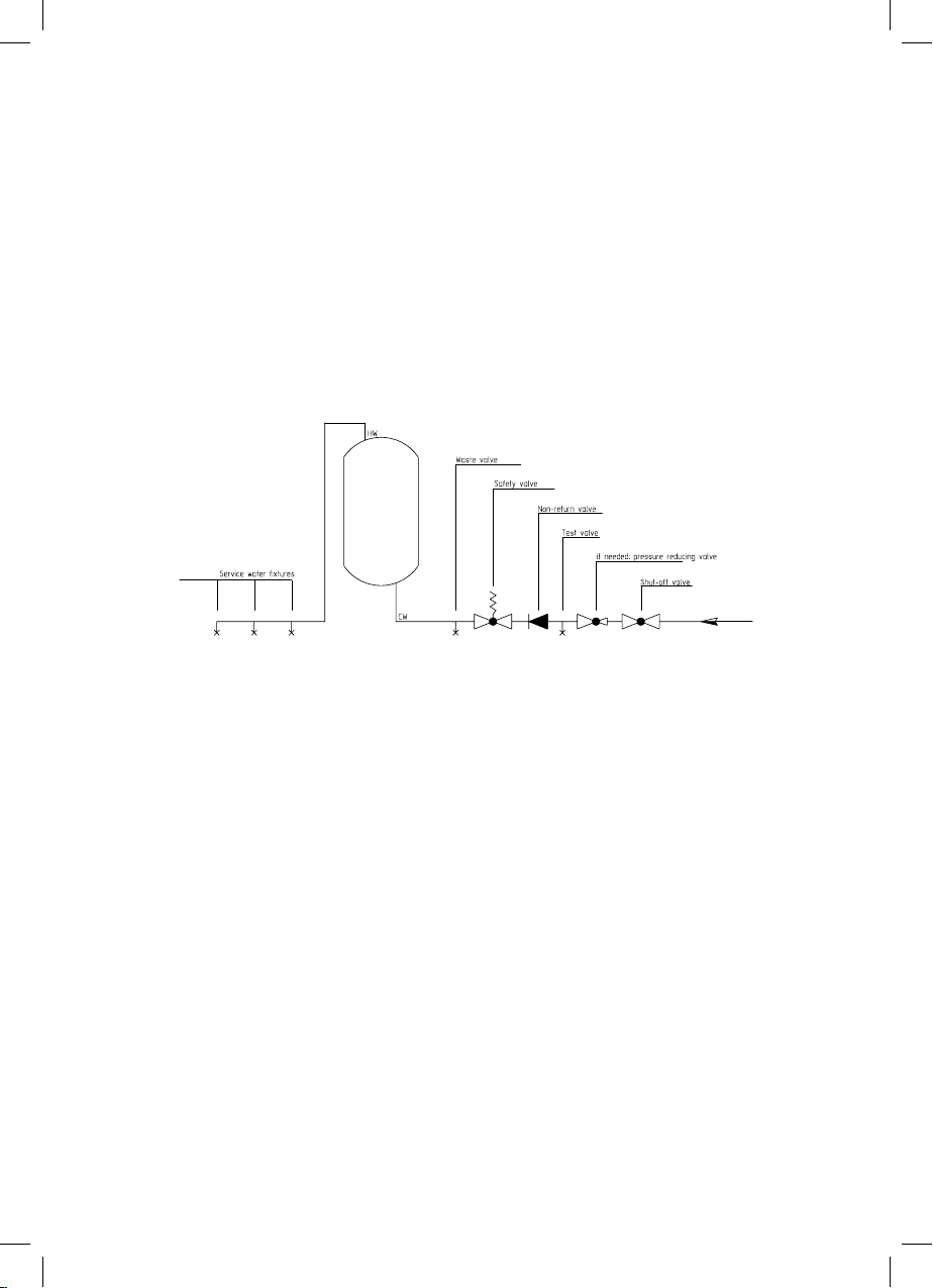
4. Service Water Connection
Pressure-proof connection
Any warranty for our water heaters shall be rejected in case of use of unsuitable or inoperative tank connector fittings as well as any exceedance of the specified operating pressure.
All water heaters of the series VT-N are provided with a rating plate bearing the designation 6 bar, those
of the series VT-S are designated 10 bar. These are pressure-proof tanks that are connected applying a
line pressure up to the height specified. A pressure reducing valve must be installed in the cold water
supply line, should the line pressure be higher. The water plumbing must be performed by means of
a certified diaphragm safety valve or a diaphragm safety valve combination (connector fitting for pressureproof storage tanks) only! A safety valve combination consists of a shutoff, test, swing check, drain and
safety valve with an expansion water drip and is installed between the cold water supply line and the cold
water supply of the storage tank in the order as drawn.
Principally, the following must be observed:
In order to ensure a flawless function of the connector fitting, the same must be mounted in frost-protected rooms only. The drain of the safety valve must be open and observable or the outlet pipe from the
drop collector (expansion water funnel) must lead into the sewer, so that neither frost nor clogging by dirt
or anything similar may cause any malfunction. Furthermore it must be observed that the drain pipe of the
safety valve be installed with a continuous downward inclination.
No shutoff valve or other throttling must be installed between the safety valve and the cold water supply of
the storage tank.
The safety valve must be set to a response pressure that is below the pressure rating of the tank. The cold
water supply line must be rinsed out before the tank is finally connected. After completed plumbing and
bubble-free filling of the tank, the connector fitting must be checked for functionality.
a) In order to avoid a blockage of the airing facility of the safety valve due to furring, the airing facility of
the safety valve must be operated from time to time during operation of the system. It must be observed whether the valve closes again after releasing the airing facility and whether the water in place
runs off completely through the funnel or the blow-off pipe.
b) In the case of safety valves that are installed ahead of water heaters, it must be observed whether
the safety valve responds during heating of the water heater. This is identifiable by the penetration of
water out of the blow-off pipe.
5
 Loading...