

Austria Email REU 18-1, REU 18-2, REU 18-3, RDU 18-2, RDU 18-3 Operator's Manual And Installation Instructions
...
Fitted Heaters
Eléments de chauffe encastrés
Riscaldatori
Calefacciones incorporadas
Aquecimentos modulares
Type:
REU
RDU
RDW
RSW
RUL
Operator’s Manual and Installation Instructions
Notice d’utilisation et de montage
Istruzioni per l’uso e il montaggio
Instrucciones de uso y de montaje
Manual de instruções e de montagem
Please provide to user
A remettre à l’utilisateur !
Consegnare all’utente!
¡Por favor, entréguese al usuario!
Repassar para o utilizador, sff.
Id-Nr.: 242782-2 • 102014 • en-fr-it-es-pt

REU - RDU - RDW - RSW - RUL
en
Dear Client!
The range of electrical tted heaters is manufactured in conformity with the applicable rules
and regulations. Their safety is tested according to ÖVE (Association of Austrian Electrical
Engineers) and/or VDE (Association of Austrian Electrical Engineers) requirements.
Installation and commissioning must be performed exclusively by a licensed installation rm
in accordance with these instructions.
This small brochure includes all important information for the correct installation and
operation of the tted heater. Notwithstanding the aforesaid, you are kindly requested to ask
your franchise owner to demonstrate the operation of the unit and explain its function. Of
course, our Customer Service Department and Sales Department will be more than happy
to provide support and advice as well.
The team is condent that your electrical tted heater will give you years of troublefree service.
Table of contents ................................................................Page
1. Function .............................................................................................7
2. Saving energy ...................................................................................7
3. Operation and temperature setting ...................................................7
4. Operating conditions ........................................................................8
5. Assembly, installation and safety information ...................................8
5.1 General installation and safety information ..............................8
5.2 Exploded views .....................................................................11
5.3Installationofthettedheater ................................................12
5.4 Notes about protection against corrosion .............................12
5.5 Connecting water to the tank ................................................13
5.6 Electrical connection .............................................................13
5.7 Commissioning .....................................................................14
6. Checking, maintenance, care ...........................................................15
7. Malfunctions .....................................................................................15
8. Technical data - electrical tted heaters...........................................16
Warranty and guarantee .......................................................................17
2 | Id.Nr.: 242782-2

REU - RDU - RDW - RSW - RUL
Cher client,
Les chauffages électriques encastrés sont fabriqués conformément aux réglementations en
vigueur et leur sécurité a été vériée par l’ÖVE ou le VDE.
L’installation et la première mise en service doivent impérativement être conées à un
installateur sous concession dans le respect de la présente notice.
Vous trouverez dans ce petit manuel toutes les instructions et conseils importants pour le
montage et l’utilisation dans les règles de l‘art. Demandez néanmoins à votre concessionnaire,
une fois l’installation terminée, de vous expliquer le fonctionnement de l’appareil et de vous
faire une démonstration de son utilisation. Bien entendu, notre service après-vente et notre
service clients se feront également un plaisir de vous conseiller.
Nous vous souhaitons beaucoup de plaisir avec votre chauffage électrique encastré.
Table des matières ................................................Page
1. Fonction ..........................................................................................19
2. Economies d’énergie ........................................................................19
3. Maniement et réglage de la température .........................................19
fr
4. Conditions de fonctionnement .........................................................20
5. Instructions de montage et d‘installation, consignes de sécurité ....21
5.1 Consignes générales d‘installation et de sécurité ...................21
5.2 Schémas d’installation ...........................................................23
5.3 Montage de l’élément chauffant encastré ..............................24
5.4 Instructions pour la protection contre la corrosion..................24
5.5 Raccordement d’eau du ballon ..............................................25
5.6 Branchement électrique ........................................................25
5.7 Première mise en service .......................................................27
6. Contrôle, maintenance, entretien .....................................................27
7. Dysfonctionnements ........................................................................27
8. Caractéristiques techniques .............................................................28
Responsabilité et garantie ....................................................................29
Id.Nr.: 242782-2 | 3
REU - RDU - RDW - RSW - RUL
it
Gentile cliente!
I riscaldatori elettrici sono prodotti in base alle norme vigenti e controllati in base alle
disposizioni di sicurezza ÖVE e VDE.
L’installazione e la prima messa in esercizio devono essere eseguite da un concessionario
autorizzata in base a queste istruzioni.
In questo opuscolo sono illustrate tutte le note importanti per un montaggio e un uso corretti
del riscaldatore. Dopo il montaggio chieda al concessionario di illustrarle i comandi e il
funzionamento dell’apparecchio. Naturalmente, in caso di bisogno, potrà contattare anche
il servizio assistenza e vendita della nostra azienda.
Siamo certi che sarà soddisfatto a lungo del suo riscaldatore elettrico.
Indice ............................................................................... Pagina
1. Funzioni ............................................................................................31
2. Risparmio energetico .......................................................................31
3. Uso e regolazione della temperatura................................................31
4. Requisiti per il funzionamento ..........................................................32
5. Note generali sul montaggio e sulla sicurezza .................................32
5.1 Note generali sul montaggio e sulla sicurezza ........................32
5.2 Schemi montaggio ................................................................35
5.3 Montaggio del riscaldatore ....................................................36
5.4 Note sulla protezione da corrosione .......................................36
5.5. Collegamento dell’acqua al serbatoio ...................................37
5.6 Collegamento elettrico ...........................................................37
5.7 Prima messa in esercizio .......................................................39
6. Controllo, manutenzione, cura .........................................................39
7. Malfunzionamenti .............................................................................39
8. Dati tecnici riscaldatori elettrici ........................................................40
Garanzia legale e contrattuale ..............................................................41
4 | Id.Nr.: 242782-2

REU - RDU - RDW - RSW - RUL
¡Estimado cliente!
Las calefacciones eléctricas incorporadas se fabrican según las normas vigentes y han
sido vericadas según la ÖVE (asociación austriaca de electrotécnica) o la VDE (asociación
alemana de electrotécnica).
La instalación y la primera puesta en servicio tiene que hacerlas imperativamente una
empresa de instalaciones de calefacción autorizada respetando las presentes instrucciones.
En este pequeño prospecto se dan todas las indicaciones importantes para el montaje y
el manejo correctos de la calefacción incorporada. Pida sin embargo al concesionario que
le explique las funciones del aparato y que le muestre cómo se maneja después de su
montaje. Naturalmente está también el servicio de atención al cliente de nuestra casa y el
departamento de ventas gustosamente a su disposición para asesorarle.
Le deseamos que disfrute de su calefacción eléctrica incorporada.
Índice ................................................................................ Página
1. Funcionamiento ................................................................................43
2. Ahorro de energía .............................................................................43
3. Manejo y ajuste de temperatura .......................................................43
es
4. Condiciones previas de uso .............................................................44
5. Indicaciones de montaje, instalación y seguridad ...........................44
5.1 Indicaciones generales de montaje y de seguridad ................44
5.2 Croquis de montaje ...............................................................47
5.3 Montaje de la calefacción incorporada ..................................48
5.4 Indicaciones sobre la protección anticorrosiva .......................48
5.5 Toma de agua del recipiente ..................................................49
5.6 Conexión eléctrica .................................................................49
5.7 Primera puesta en servicio ....................................................51
6. Control, mantenimiento, conservación ............................................51
7. Funcionamientos anómalos .............................................................51
8. Datos técnicos de las calefacciones eléctricas incorporadas .........52
Responsabilidad y garantía ..................................................................53
Id.Nr.: 242782-2 | 5

REU - RDU - RDW - RSW - RUL
pt
Prezado cliente!
Os aquecimentos eléctricos modulares são fabricados conforme as normas válidas e
testado quanto à segurança pela ÖVE e VDE.
A instalação e a primeira colocação em funcionamento somente devem ser executadas por
uma empresa de instalação concessionária conforme este manual.
Irá encontrar neste pequeno folheto todos os avisos importantes para a montagem e
operação correctos do aquecimento modular. Apesar disso, deixe que a sua concessionária
lhe demonstre o comando do aparelho após a montagem e esclareça o seu funcionamento.
Logicamente, estamos também à sua disposição com a assistência técnica aos clientes e
o departamento de vendas para a sua consulta.
Muito prazer com o seu aquecimento eléctrico de modular!
Índice ................................................................................ página
1. Funcionamento .................................................................................55
2. Poupar energia .................................................................................55
3. Operação e ajuste de temperatura...................................................55
4. Precondições de funcionamento .....................................................56
5. Indicações de montagem, instalação e segurança ..........................56
5.1 Indicações gerais de montagem e segurança ........................56
5.2 Esquemas de montagem ......................................................59
5.3 Montagem do aquecimento modular .....................................60
5.4 Avisos para a protecção contra corrosão ..............................60
5.5. Conexão da água do resservatório .......................................61
5.6 Conexão eléctrica ..................................................................61
5.7 Primeira colocação em funcionamento ..................................63
6. Controlo, manutenção, conservação ...............................................63
7. Falhas de funcionamento .................................................................63
8. Dados técnicos, aquecimento eléctricos modulares .......................64
Garantia e prestação de garantia .........................................................65
6 | Id.Nr.: 242782-2

REU - RDU - RDW - RSW - RUL
1. Function
The electrical tted heaters of the R series are the main heater for electrically heated hot
water heaters. Under normal circumstances, they do not require any maintenance or other
service intervention. However, if the lime concentration of the water is very high, it may be
necessary to remove the boiler scale at certain intervals.
The user sets the desired temperature using the control dial. During the heating interval
determined by the relevant utility, the temperature controller automatically switches the
heater on and off (when the selected water temperature for the storage tank is reached).
When the water temperature drops, for instance when water is retrieved from the tank or as
a result of natural cooling, the heater is switched on again until the actual water temperature
in the storage tank coincides with the preselected water temperature again.
2. Saving energy
Selecting a low water temperature setting for the water in the storage tank saves a lot of
energy. Consequently, it is advisable to set the innitely variable temperature controller to the
lowest temperature setting required for your actual hot water consumption. This reduces
your electricity consumption and the lime deposits in the tank.
3. Operation and temperature setting
With the innitely variable temperature controller, set the intank water temperature that suits
your requirements, or select one of the three suggested settings. In this way, you can ensure
that your tted heater works efciently without wasting energy.
To help you select an appropriate setting, the temperature control dial of the electrical heater
features 4 suggested settings marked as follows:
en
Setting: Frost protection for the tank (30 °C)
Setting: approximately 40° C, hand-hot tank water
Setting: •• approximately 65° C, moderately hot tank water This setting is
recommended to avoid accidental scalding with hot water.
Furthermore, the heater uses energy very sparingly if this setting
is selected. The heat losses are small and the formation of boiler scale is
largely prevented.
Low active standby energy consumption
Setting: ••• approximately 85° C, hot tank water
Caution:
Turning the controller counter-clockwise until the limit stop does not set the unit to zero or
switch the unit off. If the unit feeds on daytime electricity, do not select a temperature
setting higher than •• (approx. 65°C).
Due to the hysteresis of the temperature control (± 7K) and possible radiation losses
(cooling-down of the pipelines), the temperature specications are subject to an accuracy
of ± 10K.
Id.Nr.: 242782-2 | 7

REU - RDU - RDW - RSW - RUL
en
4. Operating conditions
Use tted heater exclusively in the conditions specied on the rating plate (operating pressure,
heating time, supply voltage etc.). The electrical connection must be made according to
the wiring diagram on the inside of the protection cover.
Apart from the nationally acknowledged rules and regulations (ÖVE = Association of Austrian
Electrical Engineers, VDE = Association of German Electrical Engineers, ÖNORM = Austrian
standard and DIN = German standard, etc.), the connection conditions of the local power
station and waterworks as well as the Operator’s Manual and Installation Instructions must
also be observed.
If the lime concentration of the water is very high, we recommend tting a commercially
available decalcier upstream of the water tank.
This tted heater is particularly suitable for the installation in freestanding enamelled tanks
and units with twin envelope. However, due to its special design, the units can also be tted
in third-party products with enamelled, plastic coated or hotdip galvanised boilers.
A combination with CrNi (NIRO) boilers is problematic and not recommended (necessary
measures: see item 5.4). For the installation in enamelled boilers, our tted heaters, screw-in
heaters and tted gilledpipe heat exchangers are designed with insulated heating elements
in connection with a protective current discharge resistor and therefore comply with the state
of the art – in particular concerning the protection against corrosion of enamelled boilers. All
built-in heating components are suitable for pressure- resisting operation and the heating of
drinking or heating water up to a max. operating pressure of 10 bar (150 psi).
Built-in heating systems are not suitable for use in aggressive media (alcohol, glycol,
oil, etc.)!
This device is not designed to be used by persons (including children) with physical, sensory
or mental disabilities or lacking experience and/or lacking knowledge, unless these are
supervised by a person who is responsible for their safety or have received instructions on
how to use this device from any such person. Children should be supervised in order to
ensure that they do not play with this device.
5. Assembly, installation and safety information
5.1 General installation and safety information
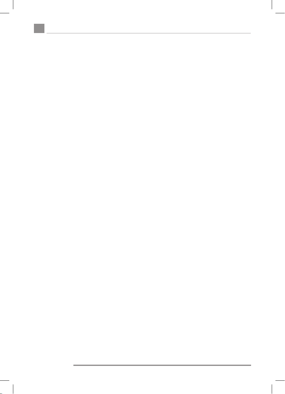
In operation, the heating element and the sensor protection tube must be surrounded on
all sides by sufcient water. The water ow resulting from thermal inuences should not be
impeded. The tted heater features a safety temperature limiter that switches off any further
heating of the unit when the water temperature reaches max. 110° C (EN 60335 -2-21;
ÖVE-EW41, Pt 2 (500) / 1971). Therefore, when selecting the connection components
(con-nection pipes, safety valve combinations, etc.), it is necessary to ensure that the
connection components will withstand temperatures of 110° C so that any consequential
damage in the event of a malfunction of the temperature controller is prevented.
The assembly and installation must be performed exclusively by authorised trade personnel.
8 | Id.Nr.: 242782-2
REU - RDU - RDW - RSW - RUL
Installation position:
Vertical installation from underneathto be used exclusively for
REU 1-… and RDU-1… types
en
Id.Nr.: 242782-2 | 9
REU - RDU - RDW - RSW - RUL
en
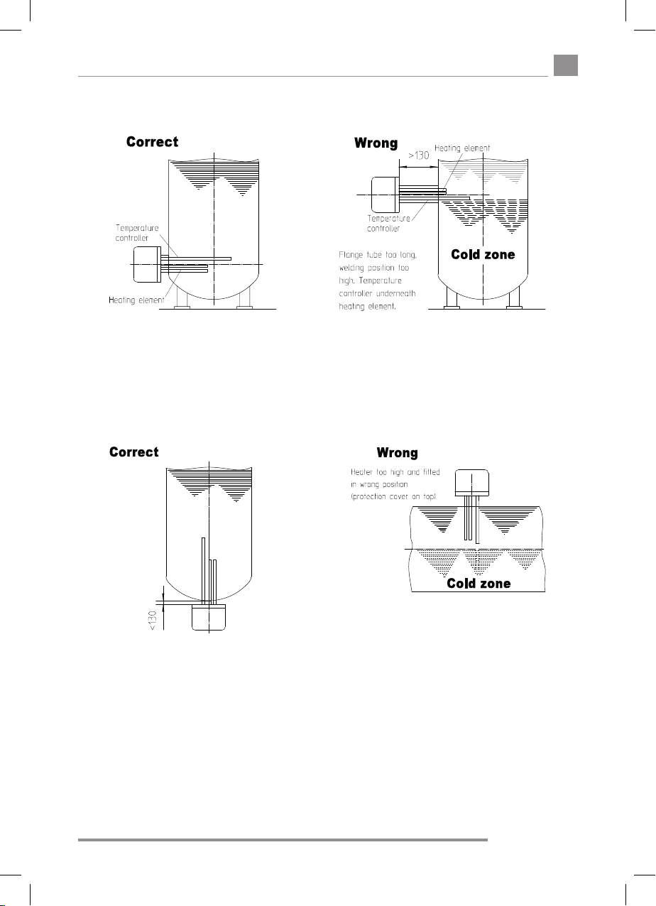
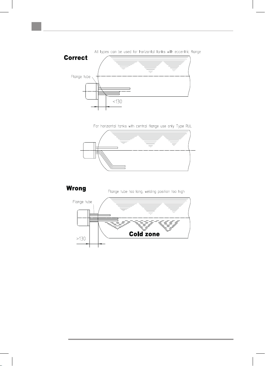
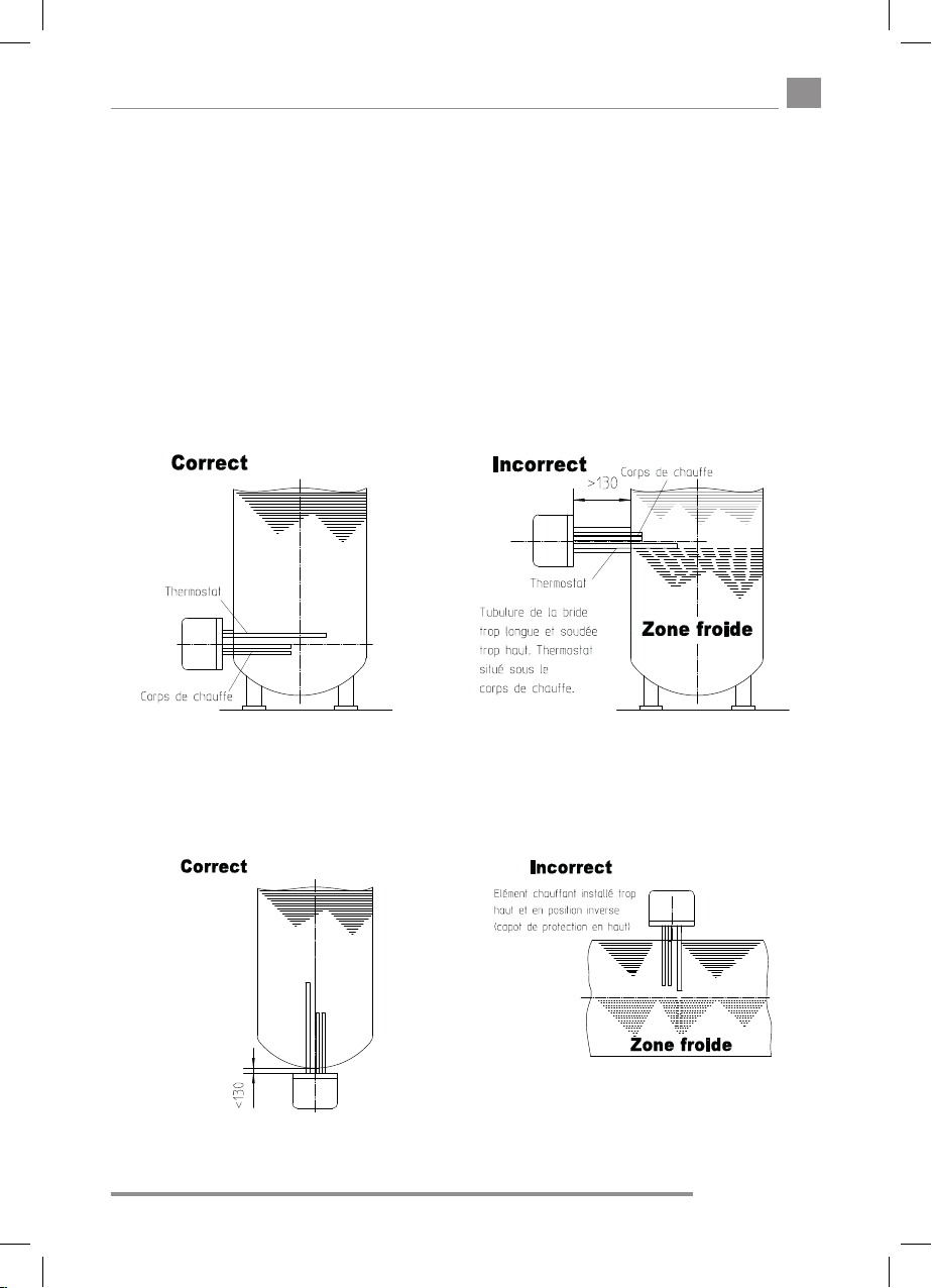
Horizontal installation in a horizontal tank
The length of the ange tube must not exceed max. 130mm in order to ensure that the
temperature sensor and the heating element extend far enough into the boiler. The heater
must be tted as low in the boiler as possible so that the entire content of the boiler is
heated evenly. It is not essential that the heating elements extend throughout the available
installation depth. In front of the boiler ange, some mounting space is required (installed
length + 100mm). Boiler scale affects the function of the heater. If the lime concentration of
the water is very high, it is necessary to take appropriate measures, for instance lowering the
temperature, installation of softening equipment, removal of the boiler scale.
10 | Id.Nr.: 242782-2
REU - RDU - RDW - RSW - RUL
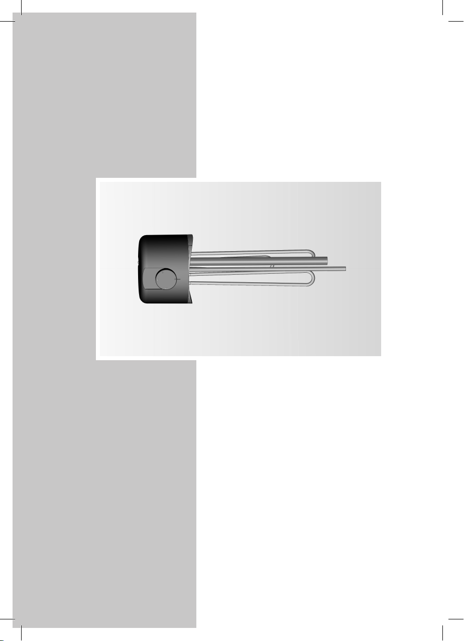
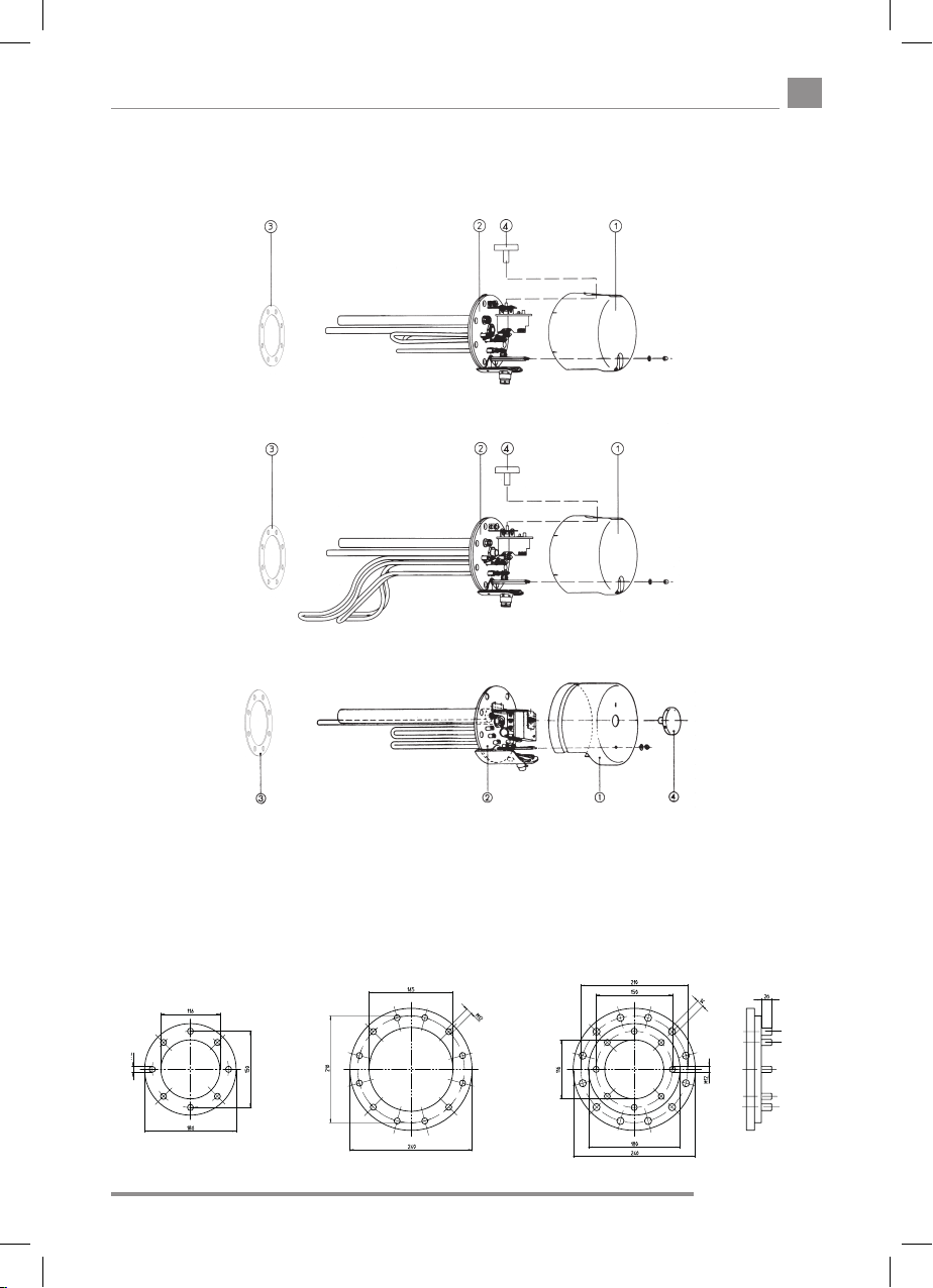
5.2 Exploded views
(The number of tubular heating elements of the individual type series differs.)
For type series REU, RDU, RSW, RDW 18 –
For type RUL 18 – 2/5
For type RDW, RSW 2 –
en
Suitable boiler anges:
For all types
R…18…(180 Ø)
For all types
R…2…(240 Ø)
12 holes
Intermediate flange
Type ZF 240-12
240 Ø, 12 holes
Id.Nr.: 242782-2 | 11

REU - RDU - RDW - RSW - RUL
en
5.3 Installation of the ttet heater
Apart from the legally acknowledged rules and regulations, the connection conditions of the
local power station and waterworks must also be observed.
1. Remove protection cover, Pos. 1.
2. Install heating ange, Pos. 2, with gasket, Pos. 3, in the boiler. During installation, the
sensor protection tube of the temperature controller must be above the tubular heating
elements (refer to “Notes on Installation”).
3. Fasten heating ange, Pos. 2, with M 12 ange bolts (max. torque: 22 Nm). Tighten
ange bolts (after tightening a bolt, proceed with the bolt in the diagonally opposite
position). Check the screw connection of the heating elements and if required retighten
to a torque of 2-3 Nm.
4. Make the electrical connection according to the wiring diagram (see Items 5/6).
Important – do not forget to connect the protective conductor!
5. Attach protection cover and fasten with nut, put on enclosed control dial, Pos. 4.
6. Do not operate until the tank is lled with water.
The installation of the heating element and commissioning must be carried out
by a skilled person who assumes the responsibility for the proper execution and
conguration in his/her capacity as a professional.
5.4 Notes about protection against corrosion
The tted heater is designed for installation in a tank with inside enamelling with a protection
anode. As delivered, the type series R…18 –… (ange diameter: 180mm) is equipped with
an anode with a diameter of 22 mm, length: 390 mm.
For enamelled boilers (third-party products), it is necessary to integrate an appropriate anode
protection in the boiler according to the manufacturer’s specications.
The protection anodes must be replaced when more than
3
/4 of the material has been
consumed. After approximately 2 years of operation, the anode should be checked for the
rst time. The degradation products of the magnesium anode can precipitate as dissolved
matter in the bottom area of the tank and also be rinsed out from the tank during the water
withdrawal.
The following measures are required in the event of a combination with CrNi (NIRO) tanks or
CrNi heat exchangers and built-in components in plastic coated tanks:
a) Disconnection of the protective current discharge resistor in order to ensure an
insulated installation of the heating element.
b) Disconnection of the anode – earth connection cable if the relevant type is
equipped with an anode.
c) Replacement of the brass sensor tube for a sensor tube made of stainless steel.
If an external current anode is retrotted, the magnesium anode installed must be removed
as otherwise the functioning of the external current anode will be impaired.
12 | Id.Nr.: 242782-2
REU - RDU - RDW - RSW - RUL
5.5 Connecting water to the tank
The assembly, connection and usage instructions of the hot water heater (boiler), as well as
ÖNORM (Austrian standard) B2531 T1 or DIN (German standard) 1988, must be observed
at all times.
Pressure-resistant connection
Any warranty is voided if inappropriate or defective tank connection ttings are used and/or
if the stated operating pressure is exceeded.To make the water connection, it is mandatory
to use a type-approved diaphragm safety valve or a diaphragm safety valve combination
– connection tting for pressureresistant tanks! A safety valve combination consists of
shutoff valve, test valve, return ow valve, drain valve and safety valve with expansion water
discharge. It is installed between the cold water supply line and the cold water inlet (blue) of
the tank in the sequence shown below.
en
5.6 Electrical connection
The installation of the heating element and commissioning must be carried out
by a skilled person who assumes the responsibility for the proper execution and
conguration in his/her capacity as a professional. As a basic rule, the electrical
connection should be made as indicated on the enclosed, type-specic wiring
diagram! Make sure the supply voltage is correct! All accessible metal parts of the
tank must be covered by the safety/protection measure.
An allpole disconnector with 3 mm contact gap width must be integrated in the power
supply line. An automatic circuit-breaker may also be used as the disconnecting device. The
connecting cable must be introduced into the connection space of the tted heater through
the attachment bolting. A cable grip (strain relief device) must be used for protection against
pulling and twisting.
Id.Nr.: 242782-2 | 13

REU - RDU - RDW - RSW - RUL
en
The connection with the power grid must be implemented in conformity with the applicable national
regulations and standards, the relevant connecting requirements of the local power company
and waterworks, as well as the standards of the Mounting and Operating Instructions, and must
be performed exclusively by a licensed electrician. The stipulated protective measures must be
executed carefully, so that no other power-supplied devices are affected thereby in the event of
a malfunction or failure of the hot water tank’s power supply (e.g. freezer, rooms used for medical
purposes, units for intensive care, etc.).
In rooms with bathtubs or showers, the device must be installed in accordance with the national
laws and regulations (e.g. of ÖVE-SEV or VDE).
The technical connecting requirements (TAB) of the relevant energy supply company must absolutely
be observed.
A residual current circuit breaker with a tripping current I
before the electric circuit.
The device must only be connected with permanently laid lines.
An allpole disconnecting unit with at least 3mm contact clearance must be connected in series
before the device. This requirement is fullled e.g. by an automatic cutout.
It is imperative that the hot water tank is lled with water prior to electrical startup.
In accordance with the safety regulations, the hot water tank must be switched powerless,
secured against being switched on again and checked for powerlessness prior to any intervention.
Interventions to the electrics of the device must only be performed by a licensed electrician.
As a rule, the electrical connection must be performed in accordance with the circuit diagram afxed
inside the connecting area of the tank!
Version with contactor control –RSW types
ÖVE (Association of Austrian Electrical Engineers) or VDE (Association of German Electrical
Engineers) tested control contactors tted outside the housing of the tted heater, for instance
in a control cabinet of the xed installation, must be used for installations and control contactors.
Separate control contactors must be used for the safety temperature limiter and the temperature
controller. The contactors must bear an inscription/label indicating their safety function for the water
heater. (TR and STB (security temperature limiter).
≤30mA must be connected in series
∆n
The output data for the choice of the contactors is given in the table (Section: Technical Data) in the
»Switching group« column. The STB (security temperature limiter) contactor must be designed for
the total output of the switching groups. When the installation has been completed, the function of
the contactors must be checked to ensure they work properly.
5.7 Commissioning
Commissioning: before the unit is switched on electrically for the rst time, the tank must be lled
with water. As the water heats up, the expansion water produced in the inner boiler must drip from
the safety valve if the connection is pressureproof and from the overow combination set if the
connection is unpressurised.
Caution: The hot water discharge pipe and parts of the safety tting can get hot.
After the tank has heated up fully, the temperature setpoint, the actual temperature of the retrieved
water and the hot water quantity display should coincide roughly.
Should a device, at the point of delivery, clearly display a malfunction, damage or other defect, this
must not be tted, installed or used in the system. Subsequent complaints regarding devices with an
obvious defect which have been connected and installed are expressly excluded under the warranty
and guarantee.
14 | Id.Nr.: 242782-2

REU - RDU - RDW - RSW - RUL
6. Checking, maintenance, care
The boiler scale as well as the furring that forms in the internal boiler of the storage tank in
the case of heavily calciferous water must be removed by an expert after one to two years
of operation. The cleaning is performed through the ange opening – de-install the built-in
heater, clean the storage tank, use a new seal when mounting the heating ange.
The internal tank of the water heater with special enamelling must not get in contact with
boiler scale solvents – do not use an antiliming pump.
Finally, the device must be rinsed thoroughly and the heating process be observed in the
same way as during the rst commissioning.
In order to be entitled to any claims for warranty, as provided, the installed reactive anode
requires documented inspection by an expert in intervals of maximum 2 years of operation.
Practically, the external current anode has an unlimited service life. Its function must be
monitored regularly by means of the control lamp.
This indicates two operating conditions:
Green: system ok
Red, ashing: malfunction - call customer service!
Pre-requisite for awless functioning is that the tank is lled with water. For proper functioning
of the external current anode, a conductivity of the medium of >150μs/cm
The guard circuit shunt resistor must not be damaged or removed during maintenance
works.
Do not use any abrasive cleaning agents and paint thinners (such as nitro, trichlor etc.) to
clean the device.
The best cleaning method is to use a damp cloth added with a few drops of a liquid household
cleaner. In hospitals and other public buildings, the prevailing regulations for cleaning and
disinfection must be observed.
During servicing works, it is advisable to open the cleaning and servicing ange in order
to inspect the tank for any foreign objects that may have been washed in as well as any
contamination, and to remove any such, if applicable.
2
is required.
en
7. Malfunctions
If the water in the tank is not heated, please check whether the circuit-breaker (MCB) in the
distributor or the fuse has tripped. Also check the setting of the temperature controller.
Please do not attempt to repair the defect in any other case. Either contact a licensed
electrician or call our customer service department. A skilled person can often repair the
unit in no time at all. When you call us to notify us of a defect, please always quote the type
name and fabrication number, which you can look up on the rating plate of your tted heater.
Id.Nr.: 242782-2 | 15
REU - RDU - RDW - RSW - RUL
en
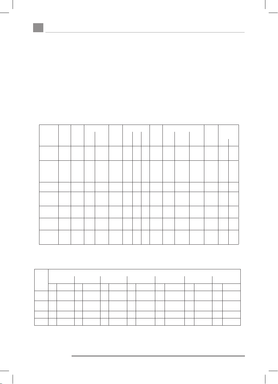
8. Technical data - electrical fitted heaters
Flange diameter 180mm (REU 18, RDU 18, RSW 18, RUL 18) – splash- proof version. Flange diameter
240mm (RDW 2, RSW 2) – drip-proof version.
Height of the protection cover: 150 mm
Innitely variable temperature controller, setting range from 40° C to approximately 85° C as well as frost protection
setting. The ange gasket is enclosed.
REU: Single-phase version for direct connection ~ 230 Volt
RDU: Three-phase version for direct connection 3 ~ 400 Volt
RSW: For horizontal installation, three-phase version for contactor control.
RUL: For horizontal tanks with central ange, reconnectable version for direct connection.
RDW: Only for horizontal installation, three-phase version for direct connection,
reconnectable heater ratings.
RSW: Only for horizontal installation, three-phase version for contactor control 3 ~ 400 Volt,
reconnectable heater ratings.
Type
REU 18-1,7
REU 18-2,0
REU 18-2,5
REU 18-3,3
RDU 18-2,5
RDU 18-3,0
RDU 18-3,8
RDU 18-5,0
RDU 18-6,0
RDW 18-7,5
RDW 18-10,0
RSW 18-12,0
RSW 18-15,0
RUL 18-2,5
reconnectab-
le to...
RDW 2-9 U
reconnectab-
le to...
RSW 2-24 U
reconnectab-
le to...
RSW 2-45 U
econnectable
to...
No-
minal
output
1,7
2,0
2,5
3,3
2,5
3,0
3,8
5,0
6,0
7,5
9,9
12,0
15,0
2,0
2,65
4,1
4,65
6,0
7,5
9,0
12,0
16,0
24,0
20,0
30,0
35,0
45,0
Connection
Nominal
voltage
direct
V
~230
x
~230
x
~230
x
~230
x
3~400
x
3~400
x
3~400
x
3~400
x
3~400
x
3~400
x
3~400
x
3~400
3~400--xx
~230
x
~230
x
3~400
x
3N~400
x
3~400
x
3~400
x
3~400
x
3~400
-
3~400
-
3~400
-
3~400
-
3~400
-
3~400
-
3~400
-
via
external
contrac-
tor
-
-
-
-
-
-
-
-
-
-
-
-
-
-
-
-
-
-
x
x
x
x
x
x
x
Switching group
Number
of
1 2 3
heating
ele-
ments
kW kW kW
1
1,7
-
1
2,0
1
2,5
1
3,3
3
2,5
3
3,0
3
3,8
3
5,0
3
6,0
3
7,5
3
9,9
331215----530
3
2
3
2,65
3
4,1
3
4,65
6
6
6
7,5
6
9
6
12
6
12
6
12
9
15
9
15
9
15
9
15
-
-
-
-
-
-
-
-
-
-
-
-
-
-
-
-
-
-
-
-
-
-
-
-
-
-
-
-
-
-
-
-
-
-
-
-
-
4
-
12
-
-
5
15
-
15
5
15
15
Ins-
talled
length
mm
450
450
450
450
450
450
450
450
450
450
450
630xx
500
500
500
500
450
450
450
530
530
530
630
630
630
630
hori-
zontal
x
x
x
x
x
x
x
x
x
x
x
x
x
x
x
x
x
x
x
x
x
x
x
x
x
Installation options
vertical
from
below
x
x
x
x
x
x
x
x
x
-
-
-
-
-
-
-
-
-
-
-
-
-
-
-
-
in
horizontal
tank
onlykW
-
-
-
-
-
-
-
-
-
-
-
--180
x
x
x
x
-
-
-
-
-
-
-
-
-
-
Flange
Mark of
diame-
conrmity
ter
mm OVE VDE
180
x
180
x
180
x
180
x
180
x
180
x
180
x
180
x
180
x
180
x
180
x
180xxxx
180
x
180
x
180
x
180
x
240
x
240
x
240
x
240
x
240
x
240
x
240
x
240
x
240
x
240
x
x
x
x
x
x
x
x
x
x
x
x
Table for the determination of the connected load (kW, tted heater type) to heat the tank water from 10° C to
85° C (reduction factor if tank water is to be heated from 10° C to 65° C: multiply value give in the table by 0.73).
Flange tube at the lowest point of the boiler.
REU 18-3,3
RDU 18-3,0
aufzuheizender Behälterinhalt
3,5 RDU 18-3,8 5,7 RDW 18-6,0 9,1 RDW 2-9 U 11,5 RSW 2-24 U
Aufheiz-
zeit
h
8 1,7 REU 18-1,7 2,3
6 2,3
4 3,4 RDU 18-3,8 4,6 RDU 18-5,0 5,7 RDU 18-6,0 6,8 RDW 18-7,5 11,3 RSW 18-12,0 18,1 RSW 2-45 U 22,7 RSW 2-24 U
3 1/3 4,1 RDU 18-5,0 5,5 RDU 18-6 6,8 RDW 18-7,5 8,2 RDW 18-10,0 13,6 RSW 18-15,0 21,8 RSW 2-24 U 27,2 RSW 2-45 U
150l 200l 250l 300l 500l 800l 1000l
kW R...Type kW R...Type kW R...Type kW R...Type kW R...Type kW R...Type kW R...Type
REU 18-2,5
2,9
RDU 18-2,5
REU 18-2,5
RDU 18-2,5
REU 18-3,3
3,1
3,9 RDU 18-3,8 4,6 RDU 18-5,0 7,5 RDW 18-7,5 11,7 RSW 2-24 U 15,1 RSW 2-24 U
RDU 18-3,0
Please note for electrical connection: The tted heater types REU, RDU, RUL, RDW can be connected
directly to the mains. For the tted heater types RSW, there needs to be a contactor in the distributor so that the
temperature sensor installed in the tted hea-ter is able to switch the voltage for the heating elements via a control
line.
16 | Id.Nr.: 242782-2
REU - RDU - RDW - RSW - RUL
Warranty, Guarantee and Product Liability
Warranty is made according to the legal provisions of the Republic of Austria and the EU.
1. The prerequisite for honoring of warranty terms on the part of the manufacturer (hereinafter referred to as Manu-
facturer) is presentation of a paid invoice for the purchase of the appliance in question, whereby the identity of the
appliance including model and fabrication number must be indicated on the invoice and presented by the claim applicant. The General Terms and Conditions, Terms and Conditions of Sale and Delivery of the manufacturer shall apply
exclusively.
2. The assembly, installation, wiring and startup of the appliance in question must, to the extent that this is prescribed
legally or in the installation and operation guide, have been performed by an authorized electrical technician or installer who has followed all the required regulations. The hot water tank (excluding outer jacket or plastic cover) must be
protected from exposure to direct sunlight to prevent discoloration of the polyurethane foam and possible cracking of
plastic parts.
3. The area in which the appliance is operated must be kept from freezing. The unit must be installed in a location where
it can be easily accessed for maintenance, repair and possible replacement. The costs for any necessary changes to the
structural conditions (e.g. doors and passages too narrow) are not governed by the guarantee and warranty declaration and therefore shall be rejected on the side of manufacturer. When erecting, installing and operating the water
heater in unusual locations (e.g. attics, interior rooms with water-sensitive oors, closets, etc.), provision must be made
for possible water leakage and means provided for catching the water with a corresponding drain to avoid secondary
damage in the context of product liability.
4. Warranty claims will not be honored for:
inappropriate transport, normal wear and tear, intentional or negligent damage, use of force of any kind or description,
mechanical damage or damage caused by frost or also by exceeding the operating pressure stated on the rating plate,
even if only once, use of connection ttings that do not comply with the standard, use of defective tank connection
ttings and unsuitable and defective service ttings. Breaking of glass and plastic components, possible colour dierences, damage due to improper use, in particular non-observance of the mounting and operating instructions (Operating and Mounting Instructions), damage by external inuence, connecting to incorrect voltage, corrosion damage
as a consequence of aggressive waters (water not suitable for drinking) in accordance with the national regulations
(e.g. Austrian ordinance on drinking water, TWV – Fed. Law Gazette II No. 304/2001), deviations between the actual
drinking water temperature at the tank tting and the specied hot water temperature of up to 10K (hysteresis of the
controller and possible cooling due to pipelines), Continued use, despite the occurrence of a defect, unauthorised modications to the device, installation of additional components that were not tested together with the device, improperly carried out repairs, Insucient water conductivity (min. 150 µs/cm) operational wear of the magnesium anode
(wearing part), natural formation of boiler scale, lack of water, re, ood, lightning, overvoltage, power failure or other
types of force majeure. Use of non-original and company-external components such as e.g. heating elements, reactive
anode, thermostat, thermometer, ribbed tube heat exchanger, etc., Parts installed in an uninsulated condition with
respect to the storage tank, ingress of foreign particles or electrochemical inuences (e.g. mixed installations), failure
to observe the design documents, unpunctual and undocumented renewal of the installed protective anode, no or
improper cleaning and operation, as well as any deviations from the standard that reduce the value or functionality of
the device only slightly. Fundamental compliance with all regulations in ÖNORM B 2531, DIN 1988 (EN 806), DIN 1717,
VDI 2035 or the corresponding national regulations and laws must be ensured.
5. A justied claim must be reported to the closest customer service location of the manufacturer. The latter reserves the
right to replace or repair a defective part or to decide whether a defective appliance shall be replaced with a working
one of equal value. The manufacturer furthermore expressly reserves the right to require that the purchaser return the
appliance in question. The time of a repair or a replacement is determined by the production.
6. Repairs made under warranty are to be performed only by persons authorized by the manufacturer. Replaced parts
become the property of the manufacturer. If any repairs to the water heater become necessary as part of necessary
service work, these are charged at the cost of repair and prorated material cost.
7. Any work performed without our express order, even this is done by an authorized installer, will void the warranty.
Assumption of the costs for repairs performed by third parties presumes that the manufacturer was requested to
eliminate the defect and did not or did not in timely fashion meet his obligation for replacement or repair.
8. The warranty period will not be renewed or extended as a result of a guarantee and warranty claim, service or mainte-
nance work.
en
Id.Nr.: 242782-2 | 17

REU - RDU - RDW - RSW - RUL
en
9. Transport damage will only be inspected and if appropriate recognized if it has been reported in writing to the manu-
facturer no later than the weekday following delivery.
10. Claims exceeding the terms of the warranty, in particular those for damage and consequential damages, are precluded
insofar as these are legally permissible. Pro rata work times for repairs as well as the costs for restoring the equipment
to its original condition must be paid in full by the purchaser. The guarantee provided extends according to this guarantee declaration only to the repair or replacement of the appliance. The provisions of the Terms of Sales and Delivery
of the manufacturer remain, insofar as they are not altered by these guarantee conditions, fully in eect.
11. There is a charge for services provided outside of the context of these guarantee conditions.
12 In order for a warranty claim to be honored by the manufacturer, the appliance must be paid for in full to the manufac-
turer and the claimant must have met all his obligations to his vendor in full.
13. The enamelled internal boiler for water heaters is warranted for the specied period from the delivery date provided all
warranty terms described under Points 1 to 12 are observed with in full. If the warranty terms have not been met, the
legal warranty requirements of the respective country from which the appliance was shipped shall prevail.
14. Claim satisfaction according to prevailing Austrian Product Liability Law:
Claims for compensation under the title of product liability are only justied if all prescribed measures and necessities
for fault-free and approved operation of the appliance have been met. This includes among other things the prescribed and documented anode replacement, connection to proper operating voltage, prevention of damage due to
improper use, etc. From these conditions it can be concluded that if all requirements are met (norms, installation and
operation guide, general guidelines, etc.), the device or product fault resulting in the secondary damages would not
have occurred. Furthermore it is mandatory that for processing of the claim the necessary documentation such as the
part number and manufacturing number of the water heater, the seller’s invoice and that of the executing license holder as well as a description of the malfunction for a laboratory study of the appliance in question (absolutely required,
since a specialist will study the appliance and analyze the cause of failure) be provided. To prevent misidentication of
the water heater during transport, it must be marked with a highly visible and legible marking (preferably including
address and signature of the end customer). Corresponding pictorial documentation indicating the extent of the damage, the installation (cold water line, hot water outlet, heating outgoing and return, safety xtures, expansion tank if
present) as well as the defect location on the water heater is also required. Furthermore the manufacturer reserves the
express right to require that the purchaser provide all the documents and equipment and equipment parts necessary
for clarication. The prerequisite for performing services under the title of product liability is that it is the claimant’s
obligation to prove that the damage was caused by the manufacturer’s product. Damage compensation according
to the Austrian Product Liability Law is subject to a 500 Euro deductible. Until the entire matter is claried and the
circumstances as well as determination of the causal factors are established, the manufacturer is held faultless. Nonobservance of the operating and installation guide and/or the relevant norms is considered negligent and will result in
a liability disclaimer within the scope of compensation for damages.
The illustrations and data are not binding and may be modied without notice when technical improvements are made.
Subject to printing errors and technical changes.
18 | Id.Nr.: 242782-2

REU - RDU - RDW - RSW - RUL
1. Fonction
Comme chauffage principal de chauffe-eau électriques, les éléments chauffants électriques de
la Série R ne requièrent aucun entretien. Uniquement en présence d’une eau très calcaire, il
peut s’avérer nécessaire de détartrer les corps de chauffe de temps en temps.
L’utilisateur peut sélectionner la température souhaitée via le bouton sélecteur. Pendant la durée
de montée en température dénie par votre société d’électricité, le régulateur de température
allume automatiquement l’élément chauffant puis l’éteint une fois la température de l’eau du
cumulus atteinte. Lorsque la température de l’eau baisse, par ex. suite à la consommation
d’eau ou au refroidissement naturel, le chauffage se déclenche et reste en marche jusqu’à ce
que la température présélectionnée soit de nouveau atteinte dans le cumulus.
2. Economies d’énergie
Limiter la température de l’eau du cumulus s’avère particulièrement économique. Pour
cette raison, il est conseillé de choisir une température, réglable graduellement, réellement
nécessaire à votre consommation d’eau chaude. Vous économiserez ainsi de l’électricité et
minimiserez les dépôts calcaires dans le ballon.
3. Maniement et réglage de la température
Vous pouvez régler la température de l’eau dans le ballon, en fonction de vos besoins en eau
chaude, soit graduellement soit sur l’un des quatre niveaux principaux clairement identiés.
Ceci vous permettra d’utiliser l’élément chauffant encastré avec une plus grande efcacité
énergétique.
fr
Pour faciliter le réglage, 4 niveaux principaux sont marqués sur le bouton du régulateur de
température, à savoir :
Position : protection antigel du cumulus (30°C)
Position : environ 40 °C, eau tiède
Position : •• environ 65 °C, eau modérément chaude
Ceci est le réglage recommandé pour éviter des brûlures par inadvertance
avec de l’eau trop chaude. En outre, l’appareil fonctionnera de manière
particulièrement économique à cette température. Les déperditions de
chaleur sont faibles et la formation de tartre est largement évitée.
Faible consommation d’énergie en veille.
Position : ••• environ 85 °C, eau très chaude
Attention :
Le réglage du bouton du régulateur en butée à gauche n’équivaut pas une position « zéro »
et n’entraîne pas la mise hors tension de l’élément chauffant.
En fonctionnement diurne, il est déconseillé de régler une température supérieure à
•• (env. 65 °C).
En raison de l’hystérèse du régulateur de température (±7K) et d’éventuelles dissipations
(refroidissement des tuyauteries), les températures sont indiquées avec une tolérance de
±10K).
Id.Nr.: 242782-2 | 19

REU - RDU - RDW - RSW - RUL
fr
4. Conditions de fonctionnement
L’utilisation de l’élément de chauffage encastré implique impérativement le respect des
conditions indiquées sur la plaque signalétique (pression de service, durée de la montée
en température, tension d‘alimentation, etc.). Le branchement électrique devra être
conforme au schéma collé sur le côté intérieur du capot de protection.
En plus de la législation et des réglementations nationales en vigueur (telles ce que celles
de la Fédération autrichienne d’ingénierie électrique ÖVE, de la Fédération allemand de
l’électrotechnique, de l’électronique et de la technique d’information VDE, des instituts de
normalisation autrichien et allemand ÖNORM et DIN, etc.), vous devez également respecter
les conditions de raccordement de votre fournisseur local d’électricité et d’eau, ainsi que les
instructions de montage et d’utilisation.
Si votre eau est très calcaire, nous vous conseillons d’installer un adoucisseur d’eau du
commerce en amont.
Cet élément chauffant encastré convient particulièrement pour être installé dans des
cumulus émaillés sur pieds ou à double paroi. Leur conception spéciale permet toutefois
d’installer ces dispositifs également dans des appareils d’autres fabricants à revêtement
émaillé, synthétique ou galvanisé à chaud. L’association avec des ballons CrNi (NIRO)
en revanche s’avère problématique et donc déconseillée (mesures nécessaires,
voir sous point 5.4). En vue de leur installation dans des ballons émaillés, nos éléments
chauffants encastrés, corps de chauffe à vis encastrés ou échangeurs de chaleur avec tuyau
à ailette encastrés sont construits, avec des éléments de chauffe de construction isolante
en combinaison avec une résistance de saignée et correspondent ainsi à l’état actuel de la
technique - notamment en matière de protection de ballons émaillés contre la corrosion.
Tous les éléments chauffants encastrés sont dimensionnés pour fonctionner à l’épreuve de
la pression et chauffer l’eau potable ou de chauffage sans toutefois excéder une pression
de service de 10 bars.
Le chauffage intégré n’a pas été conçu pour fonctionner dans des milieux agressifs
(alcool, glycol, huile, etc.) !
Cet appareil n’est pas destiné à être utilisé ou commandé par des personnes (y compris
des enfants) aux capacités physiques, sensorielles ou mentales réduites ou qui n’ont pas
l’expérience et/ou les connaissances requises à cet effet, sauf si elles sont sous la surveillance
d’une personne chargée de leur sécurité ou ont reçu l’instruction nécessaire pour utiliser cet
appareil de cette personne. Il convient de surveiller les enfants pour s’assurer qu’ils ne jouent
pas avec l’appareil.
20 | Id.Nr.: 242782-2
REU - RDU - RDW - RSW - RUL
5. Instructions de montage et d‘installation, consignes de sécurité
5.1 Consignes générales d‘installation et de sécurité
Lors du fonctionnement, le corps de chauffe et la gaine de protection de la sonde doivent
immergés dans l‘eau. Les courants d’eau entraînés par les variations de température ne
doivent pas être entravés.
L‘élément chauffant encastré est équipé d’un limiteur de température de sécurité qui arrête
l’appareil lorsque l‘eau atteint une température de 110 °C max. (EN 60335 -2-21; ÖVEEW41,
Partie 2 (500) / 1971). Il convient par conséquent de choisir les composants de raccordement
(tuyaux, groupe de sécurité, etc.) qui peuvent résister, en cas de dysfonctionnement du
thermostat, à des températures de 110 °C pour éviter tout dommage consécutif.
Le montage et l’installation sont strictement réservés à des professionnels autorisés.
Emplacement de montage :
fr
Installation verticale par le bas
Uniquement autorisée pour les types REU 1-..., RDU 1-...
Id.Nr.: 242782-2 | 21
 Loading...