

Austria Email FSN, FSN-E Operating And Installation Instructions
Operating and Installation Instructions
District heating tank
FSN and FSN-E
Please forward this on to the user!
Id.Nr.: 229224-9
2 • Id.Nr.: 229224-9
District heating tank FSN and FSN-E
Dear Customer!
You have taken the decision to purchase the hot water generation system with storage tank from our
company.
We would like to thank you for your confidence.
You will receive an elegant device built to state-of-the-art technical specifications, which complies
with all applicable regulations and has been ÖVE (Austrian Electro-technical Association)-tested. The
enamelling, which has been highly developed through continuous research, as well as ongoing quality
control during production, endows our hot water with tanks technical characteristics, which you will
always appreciate. The environmentally friendly CFC-free insulating foam ensures an extraordinarily low
standby energy consumption. For the sake of the environment, Austria Email AG's ARA (Junk Recycling Austria AG) licence enables you to have the packaging of your device professionally disposed of.
The installation and initial commissioning may only be carried out by a licensed installation company in
accordance with these instructions.
Within this small brochure you will find all important information for the correct installation and operation. But still have your licensed installer explain the functionality of the device to you and demonstrate
its operation. Of course our company is also glad to be at your disposal through the Customer Services
and Sales Departments for any advice you may require.
Enjoy your district heating tank.
Id.Nr.: 229224-9 • 3
District heating tank FSN and FSN-E
1. Description B F 4
2. Hot Water Requirements B F 6
3. Save Energy B F 6
4. Standby Energy Consumption B F 6
5. Operating B F 7
6. Temperature Setting FSN-E B F 7
7. Summer- Winter Switch B F 8
8. Thermometer B F 8
9. Adjustment Range Limitation FSN-E F 9
10. Operating Requirements B F 9
11. Installation and Safety Information F 10
12. Dimensions Sketch F 11
13. Special Suspensions B F 12
14. Connection Requirements B F 13
15. District Heating System Connection B F 14
16. Accessories and Plastic Base Installation F 15
17. Domestic Hot Water Side Connection (pressure resistant) B F 16
18. Electrical Connection (FSN-E) B F 18
18.1 General Instructions B F 18
18.2 Connection Diagram FSN-E B F 18
19. Initial Commissioning B F 19
20. Decommissioning, Draining B F 19
21. Inspection, Servicing, Maintenance B F 20
22. Malfunctions B F 20
23. Guarantee and Warranty B F 21
Information for: U = User
T = Technician
Table of Contents Page

4 • Id.Nr.: 229224-9
District heating tank FSN and FSN-E
1. Description B F
The district heating tanks are storage tanks that are heated via the district heating grid. The ow temperatures required for this should be at least 60 °C. For district heating grids that do not operate all year
round there is the option of electric heating with the FSN-E type series.
The device is distinguished by the following characteristics:
• Double enamelled steel plate internal boiler with protective anode.
• High quality heat insulation made of polyurethane foam (CFC-free); boiler foam-tted directly into the
outer casing. Benet: low standby energy consumption.
• Stove enamelled, powder coated outer casing of steel plate, white.
• Precisely displaying capillary tube thermometer.
• Domestic water heated via a coil heat exchanger. Benet: good heat layering within the boiler, good
thermal transfer.
• Zero-loss heat circuit regulation via an electrically actuated zone valve (1N ~ 230 V; 3 Watt)
with short heating up times (patent pending). This is why an electrical power supply at
1N ~ 230 V is necessary for the connection of a storage tank from the FSN or FSN-E type series.
• Elegant base to cover the connections, which is tted with a service ap for better accessibility.
Id.Nr.: 229224-9 • 5
District heating tank FSN and FSN-E
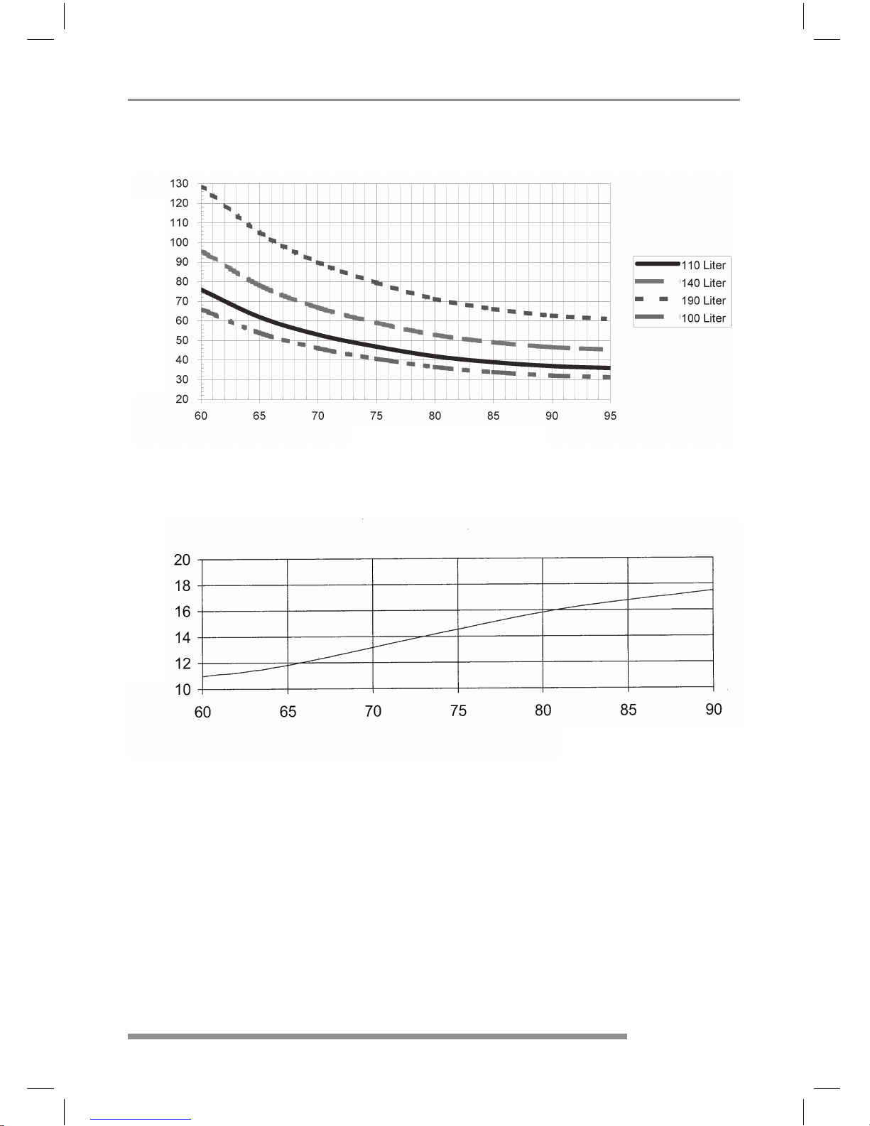
The warming-up period and the maximum input power for district heating supplies can be taken from
the following diagrams:
Warming-up Period FSN and FSN-E*
Max. input power FSN and FSN-E*
*at a primary ow volume of 300l/h
Immediately after warming up, the heating circuit is closed so that no further losses are incurred as is
usually the case due to the formation of leakage currents when the system is only regulated through
back-ow temperature limitation.
Flow temperature in °C
Power in kW Warming-up period in minutes
Flow temperature in °C
6 • Id.Nr.: 229224-9
District heating tank FSN and FSN-E
2. Hot Water B F
Hot water consumption in the household is dependent upon the number of people, the sanitary ttings
in the at or house, the insulation, the plumbing and the individual habits of the user.
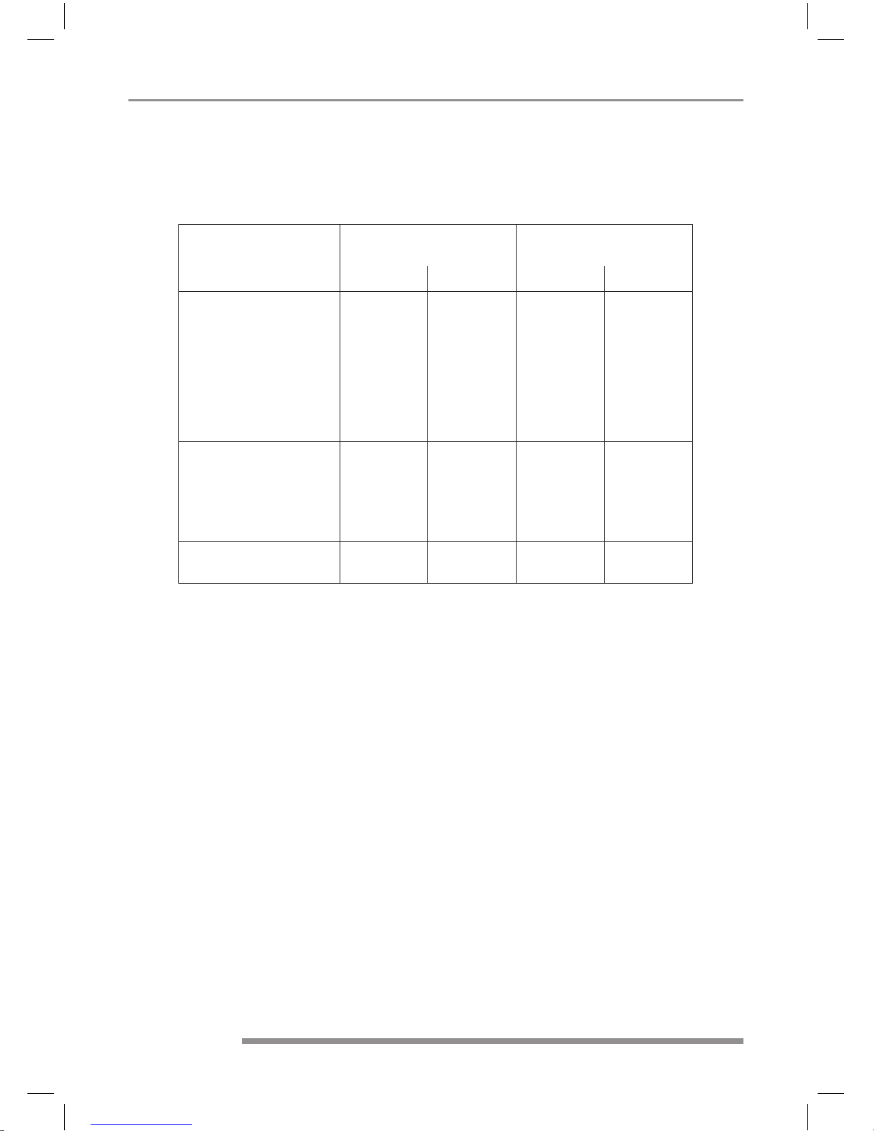
The following table provides a few standard values for consumption.
The temperature of the cold water required for mixing for the stated hot water temperature was assumed to be 12 °C.
3. Save Energy B F
Our district heating storage tanks are real energy savers due to the high quality, ecologically friendly
polyurethane foam insulation and the built-in temperature regulation system.
Low storage water temperatures turn out to be particularly economical. That is why the level of the
continuously variable temperature adjustment should only be set in accordance with the actual hot
water requirements. That helps save energy and reduces lime-scale build up within the container.
4. Standby Energy Consumption B F
If a water heater is heated up and no water is released for a long time after the heating process an,
albeit gradual but continuous, cooling of the stored water via the surface of the device will be the result.
Depending upon the construction type of the device, the size of the device, strength and quality of the
container insulation, the intensity and speed of this cooling off will vary.
This behaviour is measured at a stored water temperature of 65 °C over a period of 24 hours and
the amount of energy required to keep the water at a constant temperature throughout this period is
measured in kWh.
Standby energy consumption measured in accordance with EN 12897: max. 0,9 kW/24h
Hot water requirements
in litres
Required stored water
capacity in litres
at 37 °C at 55 °C at 80 °C at 60 °C
Bath 150 - 180 55 - 66 78 - 94
Shower 30 - 50 11 - 18 16 - 26
Hand-wash 3 - 6 1 - 2 1.6 - 3.1
Hair-wash (short hair) 6 - 12 3 - 4.4 4.2 - 6.3
Hair-wash (long hair) 10 - 18 3.7 - 6.6 5.2 - 9.4
Bidet utilisation 12 - 15 4.4 - 5.5 6.3 - 7.8
Washing dishes
for 2 people per day 16 10 14
for 3 people per day 20 12.5 18
for 4 people per day 24 15.2 21.5
Housework per bucket
of cleaning water
10 6.3 9
Id.Nr.: 229224-9 • 7
District heating tank FSN and FSN-E
5. Operating B F
All operating equipment required for the operation of the FSN and FSN-E district heating storage tanks
(temperature adjustment knob) and monitoring elements (operating light and thermometer) is gathered
together on an control panel at the front of the device.
In the case of the FSN, the temperature regulator and operating light are omitted.
This device is not designed to be operated by people (including children) with limited physical, sensory
or mental capacities or who lack the requisite experience and/or knowledge, unless they are supervised by a person responsible for their safety or have been instructed in the operation of the device
by the same. Children should be supervised in order to ensure that they do not play with the device.
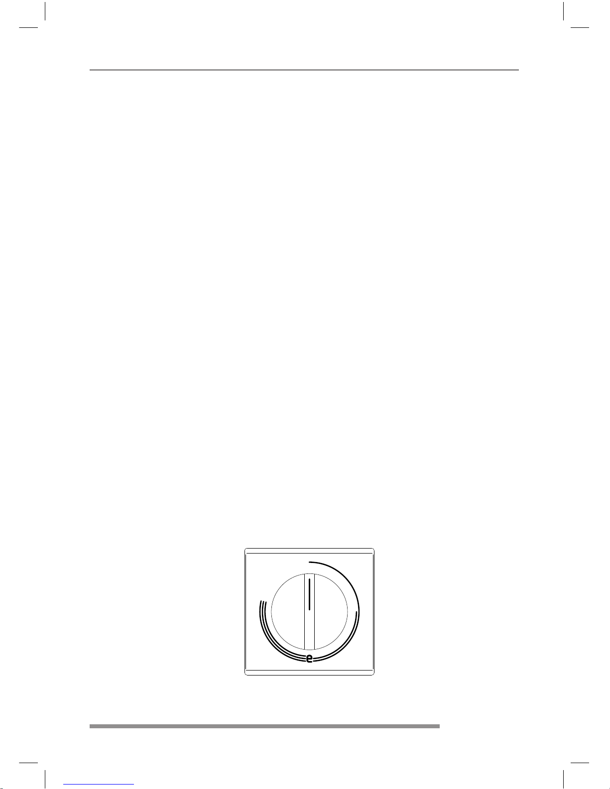
6. Temperature Setting FSN-E B F
As an aid to setting the temperature, the temperature regulator knob has 4 main positions, being:
Position: ➊ Frost protection for the storage tank (up to 30 °C)
➋ c. 40 °C, lukewarm storage water
➌ c. 65 °C, moderately hot storage water
To avoid accidental scaling with water that is too hot, this position is recommended. The device works in a particularly economical manner at this setting. The thermal losses are low and
the formation of boiler scale is largely avoided.
Low standby energy consumption
➍ c. 85 °C, hot storage water
Caution:
Turning the adjuster knob as far as possible to the left does not set the device heating at zero, nor
does it switch it off.
When operating with daytime electricity the temperature regulator should not be set any higher
than "Pos ➌" (c. 65 °C).
Due to the temperature regulator hysteresis (±7°K) and potential radiation losses (cooling of the plumbing) the temperatures quoted are subject to a tolerance of ± 10°K.
FSN 110 E
8 • Id.Nr.: 229224-9
District heating tank FSN and FSN-E
7. Summer- Winter Switch B F
Once the service ap has been opened the switch is freely accessible.
Here is where one can choose, whether the the storage tank should be powered by electricity (summertime operation) or by the district heating grid (wintertime operation).
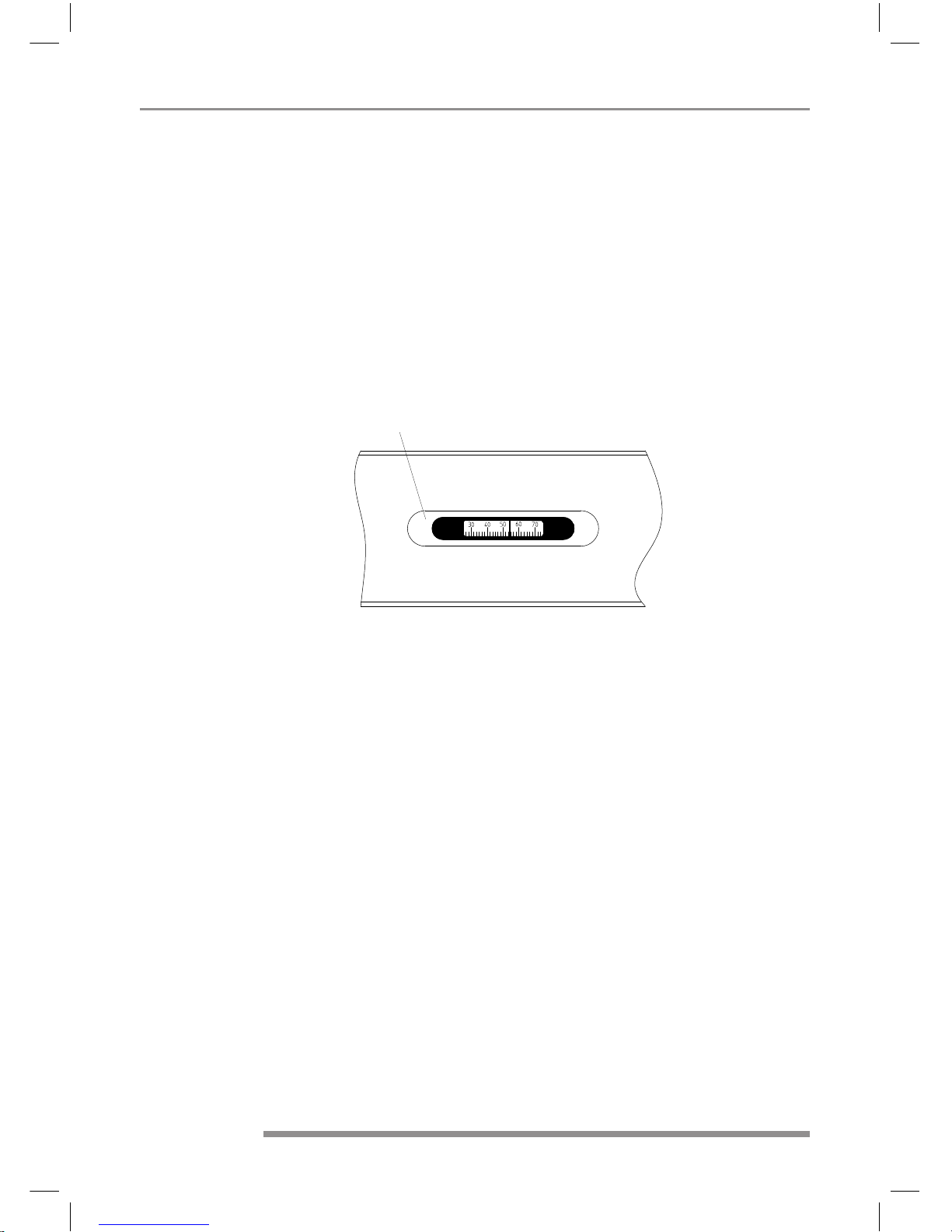
8. Thermometer B F
There is a remote thermometer built into the front panel of the device for monitoring the stored water
temperature.
The display value depends upon the temperature regulator setting. "Pos. ➍" and after completion of
the warm up process is the maximum display value reached (only in the case of electrical heating). For
other regulator positions the pointer deection is reduced accordingly.
Remote thermometer
 Loading...