

Page 1
ECO SWIFT
ECO SWIFT E
ECO SWIFT EZ
FRESHWATER STATION
CONTROLLER MANUAL
Page 2

Contents
A. Saft y instr uctions 3
A.1. EC declaration of conformity 3
A.2. General instructions 3
A.3. Explanation of symbols 3
A.4. Changes to the unit 4
A.5. Warranty and liability 4
B. Description of controller 5
B.1. Specications 5
B.2. Temperature resistance table
for Pt100 0 sensors 5
B.3. About the controller 6
B.4. Scope of supply 6
B.5. Disposal and pollutants 6
B.6. Hydraulic variants 7
C. Installation 8
C.1. Wall installation 8
C.2. Electrical connection 9
C.3. Electrical connection 10
C.4. Installing the temperature sensors 11
D. Terminal connect ion diagrams 12
E. Operation 13
E.1. Display and input 13
E.2. Menu sequence and menu structure 14
F. Parametrisation 15
F.1. Commissioning help 15
F.2. Free commissioning 15
F.3. Calibration 16
1. Measurement values 17
2. Statistics 18
2.1. Operating hours HW 18
2.2. Operating hours circ. 18
2.3. Heat output 18
2.4. Graphic overview 18
2.5. Error messages 18
2.6. Reset / clear 18
3. Operating mode 19
3.1. Automatic 19
3.2. Manual 19
3.3. Of f 19
4. Settings 20
4.1. Tset 20
4.2. Tmax 20
4.3. VFS -Type 20
4.4. Circulation 21
4.4.1. Circulation 21
4.4.2. Circ. Tmin. 21
4.4.3. Circ. hysteresis 21
4.4.4. Circ. maximum Flow rate 21
4.4.5. Circulation period 21
4.4.6. Tap support 22
4.4.7. Min storage temp 22
4.4.8. Tap support calibration 22
4.6. Zone valve 22
4.12. Comfort 22
5. Protections / Protective functions 23
5.1. Antilegionella 23
5.2. Limescale Protection 24
5.3. Discharge Protection 24
5.4. Seizing protection 24
6. Special functions 25
6.1. Pump menu 25
6.1.1. Type of pump 25
6.1.2. Pump 25
6.1.3. Output Signal 25
6.1.4. 0 -10V off / PWM of f 25
6.1.5. 0 -10V on / PWM on 26
6.1.6. 0 -10V Max / PWM Max 26
6.1.7. Show signal 26
6.2. Speed control R1 / R2 26
6.2.1. max. speed 26
6.2.2. min. speed 26
6.5. Relay functions 27
6.5.1. Circulation 27
6.5.2. Storage heating 27
6.5.2.1.Storage heating 27
6.5.2.2.Storage minimum temperature 27
6.5.2.3.SH Setpoint Temperature 27
6.5.2.4.SH hysteresis 27
6.5.2.5.Periods 27
6.5.3. Storage stratication 28
6.5.3.1.Storage stratication 28
6.5.3.2.∆T return storage 28
6.5.4. Parallel operation V1 28
6.5.4.1.Parallel operation V1 28
6.5.4.2.Delay 28
6.5.4.3.Followup time 28
6.5.5. Parallel operation V2 28
6.5.6. Always on 28
6.6. Relay 2 28
6.7. Relay 3 28
6.8. Signal V2 29
6.8.1. Signal V2 29
6.9. Pressure monitor 29
6.9.1. Pressure monitor 29
6.9.2. RPS1 / RPS2 29
6.9.3. Pmin 29
6.9.4. Pma x 29
6.10. Sensor calibration 30
6.11. Commissioning 30
6.12. Factory settings 30
6.13. Time & Date 30
6.14. Daylight saving time 31
6.15. Sleep mode 31
6.16. Temperature unit 31
7. Menu lock 32
7.1. Menu lock 32
7.2. Expert mode 32
8. Ser vice values 33
9. Language 34
Z. Malfunctions 35
Z.1. Malfunctions with error messages 35
Z.2. Replacing the fuse 36
Z.3 . Maintenance 37
Page 3
Safety instructions
A.1. - EC declaration of conformity
By afxing the CE mark to the unit the manufacturer declares that the ECO SWIFT conforms
to the following relevant safety regulations:
- EC low voltage directive 2006/95/EC
- EC electromagnetic compatibility directive 2004/108/EC
Conformity has been veried and the corresponding documentation and the EC declaration
of conformity are kept on le by the manufacturer.
A.2. - General instructions
It is essential that you read this!
These installation and operating instructions contain basic instructions and important information regarding safety, installation, commissioning, maintenance and the optimal use of the
unit. Therefore these instructions must be read completely and understood by the installation
technician/ specialist and by the system user before installation, commissioning and operation of the unit.The valid accident prevention regulations, VDE regulations, the regulations
of the local power utility, the applicable DIN-EN standards and the installation and operating
instruction of the additional system components must also be observed. The controller does
not under any circumstances replace any safety devices to be provided by the customer!
Installation, electrical connection, commissioning and maintenance of the unit may only be
carried out by specialists who possess the appropriate training.
For the user: Make sure that the specialist gives you detailed information on the function and
operation of the controller. Always keep these instructions in the vicinity of the controller.
A.3. - Explanation of symbols
Failure to observe these instructions can result in danger to life from electric
Danger
voltage.
Failure to observe these instructions can result in serious damage
Danger
to health such as scalding, or even life-threatening injuries.
Failure to observe these instructions can result in destruction of
Caution
the unit or the system, or damage to the environment.
Information which is especially important for the function and optimal use of
Caution
the unit and the system.
3
Page 4
Safety instructions
A.4. - Changes to the unit
Changes to the unit can compromise the safety and function of the unit or the entire
Danger
- Changes, additions to or conversion of the unit are not permitted without the written permission from the manufacturer
- It is likewise forbidden to install additional components that have not been tested together
with the unit
- If it becomes clear that safe operation of the unit is no longer possible, for example because
of damage to the housing, then turn the controller off immediately
- Any parts of the unit or accessories that are not in perfect condition must be exchanged
immediately
- Use only original spare parts and accessories from the manufacturer.
- Markings made on the unit at the factory must not be altered, removed or made illegible
- Only the settings actually described in these instructions may be made on the controller
A.5. - Warranty and liability
The controller has been manufactured and tested with regard to high quality
and safety requirements. The unit is subject to the statutory guarantee period
of two years from the date of sale.
The warranty and liability shall not include, however, any injury to persons or
material damage that is attributable to one or more of the following causes:
- Failure to observe these installation and operating instructions
- Improper installation, commissioning, maintenance and operation
- Improperly executed repairs
- Unauthorised structural changes to the unit
- Installation of additional components that have not been tested together with the unit
- Any damage resulting from continued use of the unit despite an obvious defect
- Failure to use original spare parts and accessories
- Use of the device for other than its intended purpose
- Operation above or below the limit values listed in the specications
- Force majeure
system.
4
Page 5
Description of controller
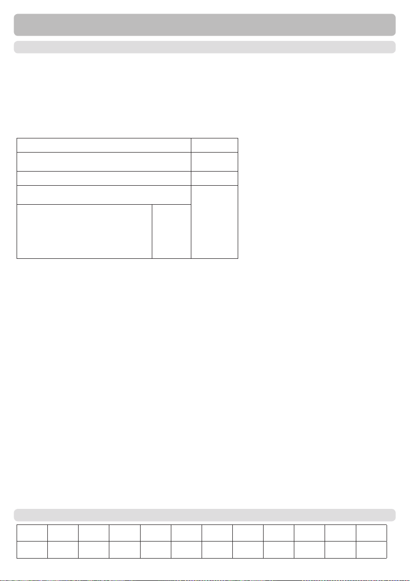
B.1. - Specications
Electrical specications:
Mains voltage 100 - 240VAC
Mains frequency 50 - 60Hz
Power consumption 0,5W - 2,5W
Internal fuse T2 A / 250V slow blow
Protection category IP40
Protection class II
Overvoltage Category II
Degree of Pollution Category II
mechanical relay 460VA for AC1 / 46 0W for AC3 3 (R1- R3)
0-10V outp ut, tolerance 10%, 10 k Ω loa d or
PWM out put freq. 1 kHz, level 10 V
PT1000 se nsor input measurin g range - 40°C to 30 0°C 6
VFS / RPS in puts
0°C -100°C (-25°C /120 °C short t erm)
1 l/m in - 12 l/min (V FS1-12)
1 l/m in - 20 l/min ( VFS1- 20)
2 l/m in - 40 l/min ( VFS2- 40)
5 l/m in - 100 l/min ( VFS5 -100)
10 l/m in - 200 l/min (VFS10- 200)
Permissible cable length of sensors and appliances:
other PT1000 sensors <10m
VFS/RPS Sensoren <3m
CAN <3m
PWM / 0...10V <3m
mechanichal relay <10m
Real Tim e Clock RTC with 24 hour power reserve
Permissible ambient conditions:
Ambient temperature
for controller operation 0°C...40°C
for transport/storage 0°C...60°C
Air humidity
for controller operation max. 85% rel. humidity at 25°C
for transport/storage no moisture condensation permiddled
Other specications and dimensions
Housing design 2-part, ABS plastic
Installation methods Wall installation, optionally panel installation
Overall dimensions 163mm x 110mm x 52mm
Aperture installation
dimensions 157mm x 106mm x 31mm
Display Fully graphical display, 128 x 128 dots
Light diode Multicolor red/green
Operation 4 entry keys
0-0,6 bar
0-1 bar
0-1,6 bar
0-2,5 bar
0- 4 bar
0- 6 bar
0-10 bar
2
2
B.2. - Temperature resistance table for Pt1000 sensors
°C 0 10 20 30 40 50 60 70 80 90 100
Ω 1000 1039 1077 1116 1155 1194 1232 1270 1308 1347 1385
5
Page 6
Description of controller
B.3. - About the controller
The Fresh water controller ECO SWIFT facilitates efcient use and function control through
of your fresh water system. Tap water temperature is regulated fast and precise. The device
is impressive most of all for its functionality and simple, almost self-explanatory operation.
For each step in the input process the individual entry keys are assigned to appropriate functions and explained. The controller menu contains headwords for the measured values and
settings, as well as help texts or clearly-structured graphics.
Important characteristics of the ECO SWIFT:
- Depiction of graphics and texts in a lighted display
- Simple viewing of the current measurement values
- Analysis and monitoring of the system by means of statistical graphics,etc.
- Extensive setting menus with explanations
- Menu block can be activated to prevent unintentional setting changes
- Resetting to previously selected values or factory settings
B.4. - Scope of supply:
- Fresh water controller ECO SWIFT
- replacement fuse 2A slow-blow
- Installation and operating instructions ECO SWIFT
Optionally contained depending on design/order:
- Pt1000 temperature sensor and Vortex Flow Sensor
B.5. - Disposal and pollutants
The unit conforms to the European RoHS directive 2011/65/EU for the restriction of the use
of certain hazardous substances in electrical and electronic equipment.
The unit must not under any circumstances be disposed of with ordinary
Caution
6
household refuse. Dispose of the unit only at appropriate collection points or ship it
back to the seller or manufacturer.
Page 7
Description of controller
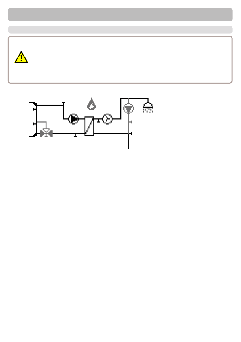
B.6. - Hydraulic variants
The following illustrations should be viewed only as schematic diagrams showing
the respective hydraulic systems, and do not claim to be complete. The controller
does not replace safety devices under any circumstances. Depending on the spe-
Caution
cic application, additional system components and safety components may be
mandatory, such as check valves, non-return valves, safety temperature limiters,
scalding protectors, etc., and must therefore be provided.
S3
S4
S5
VFS
S1
S2
S6
7
Page 8
C.1. - Wall installation
Install the controller only in dry areas and under the ambient conditions
Caution
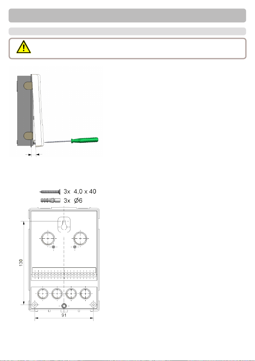
described under 2.1 “Specications”. Carry out the following steps 1-8.
Installation
Fig.C.1.2
A
Fig.C .1.1
1.Unscrew cover screw completely
2.Carefully pull upper part of housing
from lower part.
3.Set upper part of housing aside, being
sure not to touch the electronics when
doing so.
4.Hold the lower part of the housing up
to the selected position and mark the 3
mounting holes. Make sure that the wall
surface is as even as possible so that the
housing does not become distorted when
it is screwed on.
5.Using a drill and size 6 bit, drill 3 holes
at the points marked on the wall and push
in the plugs.
6.Insert the upper screw and screw it in
slightly.
7.Fit the upper part of the housing and
insert the other two screws.
8. Align the housing and tighten the three
screws.
8
Page 9
C.2. - Electrical connection
Before working on the unit, switch off the power supply and secure it against being
switched on again! Check for the absence of power! Electrical connections may
Danger
only be made by a specialist and in compliance with the applicable regulations. Do
not use the controller if the housing shows visible damage.
Low-voltage cables such as temperature sensor cables must be routed separately
from mains voltage cables. Feed temperature sensor cables only into the left-hand
Caution
side of the unit, and mains voltage cables only into the right-hand side.
The customer must provide an all-pole disconnecting device, e.g. a heating emer-
Caution
gency switch.
The cables being connected to the unit must not be stripped by more than 55mm,
Caution
and the cable jacket must reach into the housing just to the other side of the strain
relief.
Controller and VFS sensor have to have the same ground potential. The VFS
Caution
sensor uses a functional earth connector (PELV). The PE-connector of the
controller has to be connected to the pipe system near the sensor.
Installation
9
Page 10
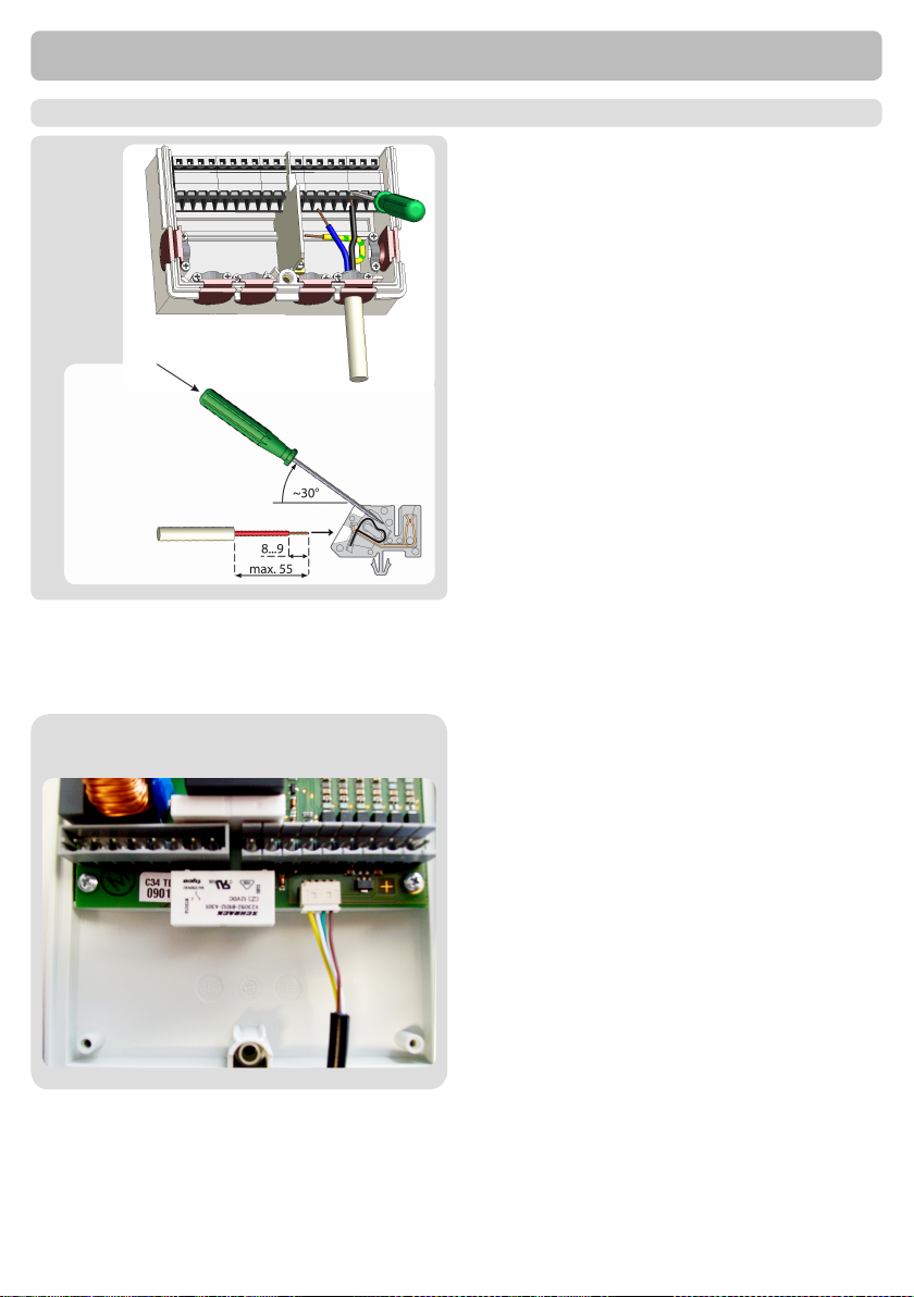
C.3. - Electrical connection
C.3.1.
C.3.2.
Installation
1. Select necessary program/ hydraulics
2. Open controller
3. Strip cables by 55mm max., insert, t the
strain relief devices, strip the last 8-9mm
of the wires. (Fig. C.3.1)
4. Open the terminals using a suitable
screwdriver (Fig. C.3.2) and make electrical
connections on the controller
5. Connect the ow sensor to the socket
on the board (Fig. C.2.3.).
6. Ret upper part of housing and fasten
with screw.
7. Switch on mains voltage and place controller in operation.
C.3.3.
10
Page 11
Installation
C.4. - Installing the temperature sensors
The controller operates with Pt1000 temperature sensors which are accurate to the
degree, thus ensuring optimal control of system functions.
Position the sensor precisely in the area to be measured!
It is recommended that at least 20 cm of the sensor cable at the sensor are installed inside the
pipe insulation.
Connect the VFS sensors with the matching jacks.
Sensor cables for PT1000 can be extended to a maximum of 10m using a
cable with a cross-section of at least 0.75mm².
Caution
Caution
Caution
Sensor cables for the VFS sensor can be extended to 3m.
Make sure that there is no contact resistance!
The temperature sensor cables must be routed separately from mains voltage
cables, and must not, for example, be routed in the same cable duct!
Controller and VFS sensor have to have the same ground potential. The VFS
sensor uses a functional earth connector (PELV). The PE-connector of the
controller has to be connected to the pipe system near the sensor.
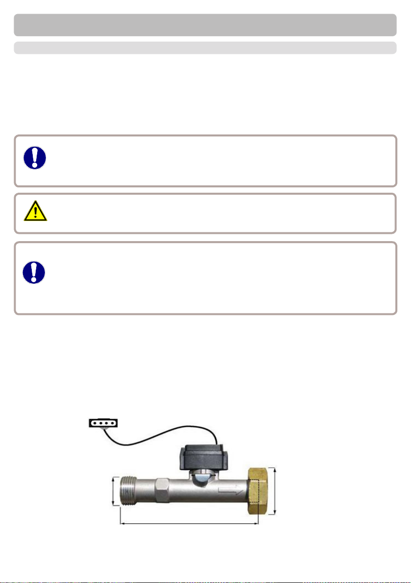
Example:
Connections and dimensions of the Vortex Flow Sensors VFS2-40
3/4 “
10,7 cm
1 “
11
Page 12
Installation
S6V1V2
+
S5
S4 S3 S2 S1
-
PELV
R3I
R3 R2 R1 L N
VFS2 VFS1CAN CAN
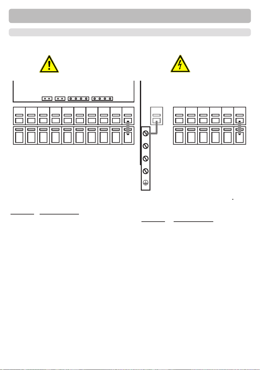
D. - Terminal connection diagrams
D.1. - „With circulation pump“
Sensor side
max. 12V
Caution
Low voltage max. 12VAC/DC connection in
the left-hand terminal compartment!
Terminal: Connection for:
S1 Circulation (opt.)
S2 Cold water (optional, see box below)
S3 Primary ow (opt.)
S4 Storage top (opt.)
S5 storage middle (opt.)
V1 0-10V/PWM signal primary pump
V2 0-10V/PWM signal (opt.)
S6 Primary return ow (opt.)
- Terminal connection sensor VFS1 Warm water tap
Mains voltages 230VAC 50-60Hz
Connection in the right-hand terminal
compartment!
Terminal: Connection for:
L Mains phase conductor L
N Mains neutral conductor N
R1 Primary pump (opt.)
R2 Relay 2
R3 Relay 3 (normally open)
R3I Relay 3 (normally closed)
The PE protective conductor must be
connected to the PE metal terminal block!
Mains side
230VAC
Danger
VFS2 optional
The polarity of the sensors is freely selectable.
Relay connection changes depending on the additional functions selected.
Connection of sensor earths (1-6) via terminal block sensor(-)
VFS sensor has to be connected to the socket on the circuit board.
Sensor 2 / Cold water: If no sensor is connected, a temperature of 10° C is set. See also „6.2
Sensor calibration“
12
Page 13
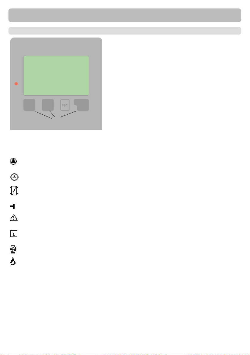
E.1. - Display and input
(1)
(2)
(3)
(4)
Examples of display symbols:
Pump
(rotates in operation)
Flow meter
heat exchanger
Temperature sensor
Warning/error message
New information available
Valve (ow direction black)
Operation
The display (1), with its extensive text and graphics
mode, is almost selfexplanatory, allowing easy operation of the controller.
The LED (2) lights up green when a relay is switched
on.
The LED (2) lights up red when
operating mode “Off” is set.
The LED (2) ashes slowly red in the operating mode
“Manual”.
The LED (2) ashes quickly red when an error is
present.
Entries are made using four keys (3+4), which are assigned to different functions depending on the situati-
on. The “esc” key (3) is used to cancel an entry or to
exit a menu. If applicable there will be a request for
conrmation as to whether the changes which have
been made should be saved. The function of each
of the other three keys (4) is shown in the display line
directly above the keys; the right-hand key is general-
ly has a conrmation and selection function.
Examples of key functions:
+/- = enlarge/shrink values
▼/▲ = scroll menu down/up
yes/no = approve/reject
Info = additional information
Back = to previous screen
ok = conrm selection
Conrm = conrm setting
Thermostat
13
Page 14

Operation
E.2. - Menu sequence and menu structure
The graphics or overview mode appears when no
key has been press for 2 minutes, or when the main
menu is exited by pressing “esc“.
Pressing a key in graphics or overview mode takes
you directly to the main menu. The following menu
items are then available for selection there:
Current temperature values with explanations
7. Protective functions
8. Menu block
9. Service Values
14
Function control of the system with operating hours,
etc.
Select graphics mode or overview mode
Automatic mode, manual mode or switch unit off
Set parameters needed for normal operation
Program selection, clock, etc.
Functions to prevent damage to system and user.
Against unintentional setting changes at critical
points
For diagnosis in the event of an error
Page 15
Parametrisation
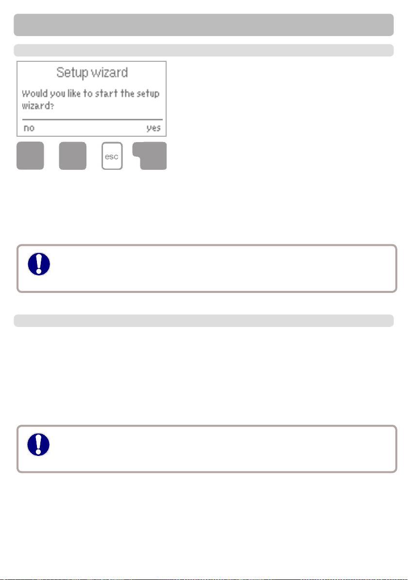
F.1. - Commissioning help
The rst time the controller is turned on and after the
language and time are set, a query appears as to whether you want to parametrise the controller using the
commissioning help or not. The commissioning help
can also be terminated or called up again at any time
in the special functions menu. The commissioning
help guides you through the necessary basic settings
in the correct order, and provides brief descriptions
of each parameter in the display. Pressing the “esc”
key takes you back to the previous value so you can
look at the selected setting again or adjust it if desired. Pressing the “esc“ more than once
takes you back step by step to the selection mode, thus cancelling the commissioning help.
Finally, menu 4.2 under operating mode “Manual” should be used to test the switch outputs
with the consumers connected, and to check the sensor values for plausibility. Then switch
on automatic mode.
Observe the explanations for the the individual parameters on the
Caution
following pages, and check whether further settings are necessary
for your application.
F.2. - Free commissioning
If you decide not to use the commissioning help, you should make the
necessary settings in the following sequence:
- Menu 6. Special functions - clock, Additional functions
- Menu 5. Settings, complete
Finally, menu 4.2 under operating mode “Manual“ should be used to test the
switch outputs with the consumers connected, and to check the sensor values for plausibility.
Then switch on automatic mode.
Observe the explanations for the the individual parameters on the following pages,
Caution
and check whether further settings are necessary for your application.
15
Page 16

Parametrisation
F.3. - Calibration
When the tap support is activated (during commissioning or in the menu „Circulation“), a calibration process is started after the commissioning. To ensure the correct operation, calibration is
also scheduled to start on every Sunday at 3:00 AM.
During commissioning, the calibration must not be interrupted.
If the weekly calibration process is not successful after 10 minutes, the process is cancelled
and the controller uses the former calibration values.
Calibration
During the callibration process a text is shown that the ow rate is measured and no tapping
is allowed.
After conrmation the circulation pump is switched off and the controller is waiting until the ow
rate has dropped to 0 L/min. Afterwards only the circulation pump is switched on and after another
60 seconds the ow rate is measured. The display shows a “Please wait” sign.
After another minute, the ow rate is measured again, and the two ow rates are compared.
If the results are identical (+- 1L/min), the result is saved.
If not, the process is started over until either the results match or 10 minutes have passed and
the calibration is cancelled and the former values are used.
16
Page 17

Measurement values
1. - Measurement values
If “Error” appears on the display instead of the measurement value,
then there may be a defective or incorrect temperature sensor.
If the cables are too long or the sensors are not placed optimally, the result may
Caution
be small deviations in the measurement values. In this case the display values
can be compensated for by making entries on the controller. Follow the instructions under 12.3.
What measurement values are displayed depends on the selected program, the
connected sensors and the specic device design.
The menu “1. Measurement values” serves to dis-
play the currently measured temperatures.
The menu is closed by pressing “esc” or selecting
“Exit measurement values”.
17
Page 18
Statistics
2. - Statistics
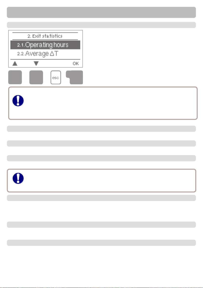
The menu “2. Statistics” is used for function control and
long-term monitoring of the system. The submenus
described under 7.1-7.6 are available.
The menu is closed by pressing “esc” or selecting “Exit
statistics”.
For system data statistics it is essential for the time to be set accurately on the controller. Please note that the clock continues to run for about 24 hours if the mains voltage
Caution
2.1. - Operating hours HW
Display of operating hours of the relays connected to the controller.
2.2. - Operating hours circ.
Display of operating hours of the circulation pump connected to the controller.
is interrupted, and after that has to be reset. Improper operation or an incorrect time
may result in data being cleared, recorded incorrectly or overwritten. The manufacturer
accepts no liability for the recorded data!
2.3. - Heat output
Display of the heat output of the system in KWh
Resulting data is only approximate value for function control!
Caution
2.4. - Graphic overview
This provides a clearly-organised display of the data listed under 2.1 - 2.2 as a bar graph. Various time ranges are available for comparison. The two left-hand keys can be used to page
through the data.
2.5. - Error messages
Display of the last 15 errors occurring in the system with indication of date and time.
2.6. - Reset / clear
Resetting and deleting the individual analyses. The function “All statistics” clears all analyses
but not the error messages.
18
Page 19
3. - Operating mode
3.1. - Automatic
Automatic mode is the normal operating mode of the controller. Only automatic mode
provides proper controller function taking into account the current temperatures and the
Caution
3.2. - Manual
Danger
parameters that have been set! After an interruption of the mains voltage the controller
automatically returns to the last operating mode selected!
When operating mode “Manual” is activated, the current temperatures and the selected
parameters are no longer considered. There is a danger of scalding or serious damage
to the system. The operating mode “Manual” may only be used by specialists for brief
function tests or during commissioning! The relay and thus the connected consumer
are switched on and off by pressing a key, with no regard to the current temperatures
and the parameters which have been set. The measured temperatures are also shown
to provide an overview and function control.
Operating modes
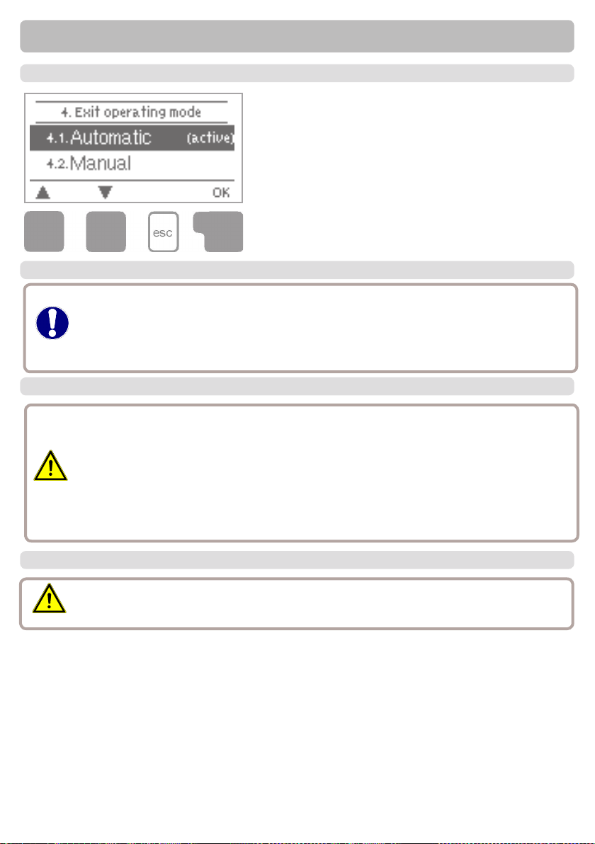
In menu “4. Operating modes” the controller can either
be placed in automatic mode, switched off, or placed
in a manual operating mode.
The menu is closed by pressing “esc” or selecting “Exit
operating modes”.
3.3. - Off
Caution
When the operating mode “Off” is activated, all controller functions are switched off.
The measured temperatures are still displayed to provide an overview.
19
Page 20
Settings
4. - Settings
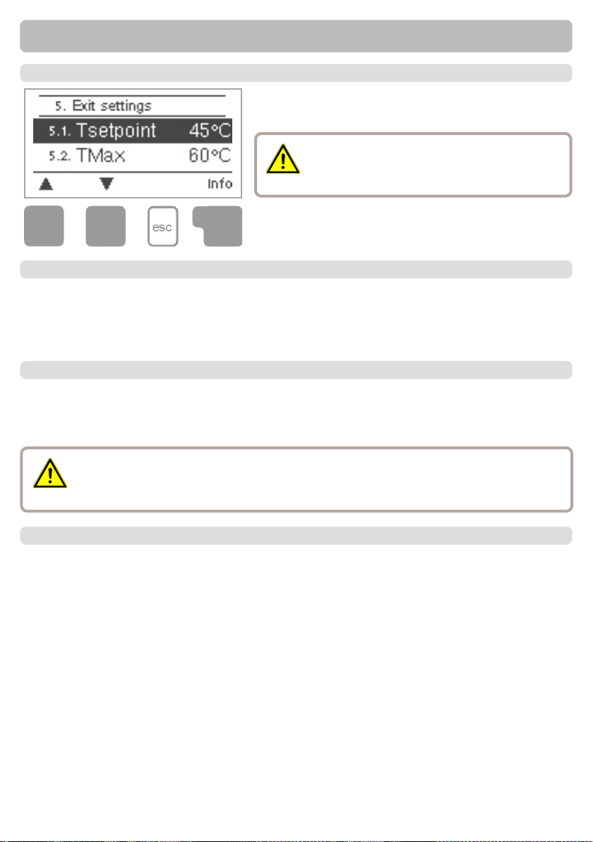
The necessary basic settings required for the control
function are made in menu “5. Settings”.
This does not under any circumstances re-
Caution
The menu is closed by pressing “esc” or selecting “Exit
settings”.
4.1. - Tset
Setpoint at sensor 5
The controller ECO SWIFT attempts to reach and maintain a constant temperature in the circulation by controlling the speed of the hot water pump.
4.2. - Tmax
Maximum tap water temperature at VFS
Maximum allowable temperature at VFS. If Tmax is exceeded, the pump is switched off. If the
temperature drops below Tmax the pump is switched on again.
place the safety facilities to be provided by
the customer!
Temperature values which are set too high can lead to scalding or damage to the
Danger
4.3. - VFS -Type
Set the type of Vortex Flow Sensors
In this menu the type of Vortex Flow Sensor can be set.
20
system. Scalding protection must be provided by the customer!
Page 21
Settings
4.4. - Circulation
4.4.1. - Circulation
Mode of circulation
When the mode “Request” is active, the circulation pump is switched on after a corresponding
tapping of water has occured and stays on until the circulation target temperature (Circ Tmin +
hysteresis) is reached at the circulation sensor.
In mode “Periods” the circulation pump is enabled in the set periods and the set circulation
minimum temperature is undershot and stays on until the circulation target temperature (Circ
Tmin + hysteresis) is reached at the circulation sensor.
Request+Time: The circulation pump is switched on in the enabled periods and the set circulation minimum temperature is undershot, or when water is tapped. Circulation stays on till the
circulation target temperature (Circ Tmin + hysteresis) is reached at the circulatiopn sensor.
Always on: Circulation pump is switched on in set periods.
4.4.2. - Circ. Tmin.
Minimum temperature at sensor S2
If the temperature drops below Circ.Tmin and the circulation is enabled (see „4.4.5. Circulation period“), the circulation pump is started.
4.4.3. - Circ. hysteresis
Switch-off hysteresis of the circulation pump
If the temperature exceeds TminS2 by this value, the circulation pump is switched off.
4.4.4. - Circ. maximum Flow rate
Maximum ow rate of the circulation pump
If the ow rate measured at sensor 6 exceeds this value (because water is being drai-
ned from the system) the circulation pump is switched off.
4.4.5. - Circulation period
Period where the circulation pump is enabled. Set the operation times of the circulation pump. 3
different periods can be set for every weekday, which can also be copied to other days.
In periods not dened circulation is inactive.
Caution
The set periods are only used in the circulation mode “Periods”.
21
Page 22

Settings
4.4.6. - Tap support
To ensure a constant temperature even with small amount of tap water, the circulation pump can
be used as support pump.
but also when a small tapping occurs. When a storage sensor is connected, tap support is only
switched on when the Min storage Temp is reached at the storage sensor.
Settings range: On, Off / Default: On
4.4.7. - Min storage temp
Tap support is deactivated when the storage temperature drops below „Min storage temp“.
4.4.8. - Tap support calibration
If the tap support is activated in the menu “Circulation” or in the Setup
Wizard,acalibration is automatically started after the commissioning.
Calibration will be repeated once per week (sundays at 03:00 clock) when there is no
tapping activity.
During commissioning, calibration may not be cancelled.
If the weekly calibration is not completed successfully after 10 minutes , it will be cancelled automatically and the controller continues with the „old „ values .
Calibration Procedure:
During calibration, a message appears that the ow rate is detected and no tapping is
allowed in the meantime.
After conrmation, the circulation pump switches off and the controller waits until the
ow has fallen to 0L/Min. Afterwards, only the circulation pump switches on and waits
for 60 seconds. An alert in the display will ask to wait.
After 60 seconds, the current ow rate is detected and stored. Then, the controller waits
an additional 60 seconds and then compares the measured values. If the ow rates
(+- 1L / Min) do not match, the controller stores the new value and waits another 60
seconds. This is repeated until the values match, or operation is cancelled by the maximum term of 10 minutes.
Not only does the circulation pump switch on under normal conditions,
4.6. - Zone valve
This function switches a valve which passes the return ow into the lower or middle
storage zone. The difference between return ow and storage temperature has to be set
here. If the return ow temperature exceeds the storage temperature by this difference,
the return ow will pass into the middle storage zone. If no storage sensor is connected,
the storage temperature is set to 25°C.
4.12. - Comfort
If this function is activated, the heat exchanger will rinse for 5 seconds every 15 minutes,
so that hot water is available as soon as possible.
22
Page 23
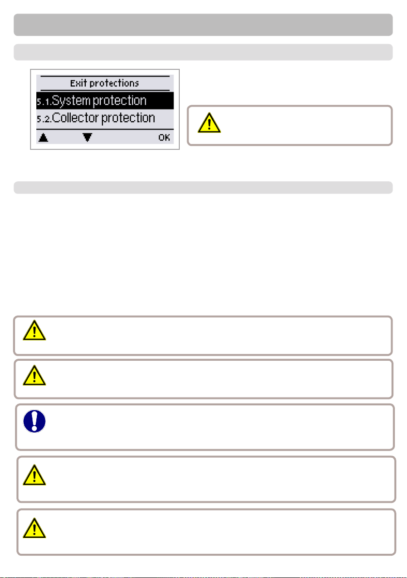
Protective functions
5. - Protections / Protective functions
Menu „5. - Protections / Protective functions“
can be used to activate and set various protective functions.
This does not under any circum-
Caution
The menu is closed by pressing “esc” or
selecting “Exit”.
5.1. - Antilegionella
With the AL-function activated, the ECO SWIFT 3 makes it possible to heat the storage in selectable intervals, (AL interval) for the set residence time (AL resid. time), starting at the set time
(AL start time) until the temperature AL Tset is reached. The temperature measured at S5 has
a reference of AL Tset +5°. For the time the AL function is active, Tmax is set to AL Tset +10° to
prevent system shutdown due to high temperature.
Only when a temperature of at least „AL Tset“-5°C is reached at the Hot water sensor and, if
present, at the circulation sensor for the time set in „Al resid. time“, the AL function is regarded
as succeful. This is displayed as “Last AL heat.”. If AL is unsuccessful after 2 hours, the attempt
is canceled and will be started again the next day and an error message is displayed.
stances replace the safety facilities
to be provided by the customer!
Danger!
Caution
Caution
Caution
Caution
During the anti-Legionella function the storage tank is heated up to high temperatures
which can lead to scalding and damage to the system.
The user has to make sure that the antilegionella function was succesful at the set
intervals.
The AL function is switched off by default. A message also containing the date is shown
as soon as the AL function was completed successful. We recommend to set the „AL start
time“ in a period where little or no withdrawal of water takes place.
The user has to make sure that the storage temperature is AL Tset +5° when starting AL. When the storage sensor S3 is installed: If AL Tset+5° is not reached, the AL
function is not started.
This anti-Legionella function does not provide complete protection against Legionella,
because the controller is dependent on sufcient energy being fed in.
23
Page 24

Protective functions
5.2. - Limescale Protection
To prevent the accumulation of limescale, the circulation pump can continue to rinse
the heat exchanger after a tapping for at least 5 seconds or for longest 30 seconds or
till the VFS sensor drops below Tset.
5.3. - Discharge Protection
If the temperature in the primary circuit is not always guaranteed to sufce, this function is used.
With this function activated:
When no storage sensor is connected:
If the setpoint temperature is not reached after 60 seconds, the currently measured temperature -3°C is used as new setpoint temperature. Once the pump in the primary circuit stops, the
setpoint temperature is raised to the set Tset again.
When the storage sensor is connected
If the temperature at the storage sensor is smaller than Tset -5°C, the target temperature is
lowered to the currently measured storage temperature -5°C.
In both cases “Circ Tmin” is lowered to the new setpoint temperature - Circ. hysteresis - 5°C,
where “Circ Tmin is not lower than 0° C and not higher than the set Circ Tmin.
5.4. - Seizing protection
If the seizing protection is activated, the controller switches the output in question and
the connected consumer on every day at 12:00 (setting “daily”) or weekly on Sundays
at 12:00 (setting “weekly”) for 5 seconds in order to prevent the pump and/or the valve
from sticking after an extended stationary period.
24
Page 25
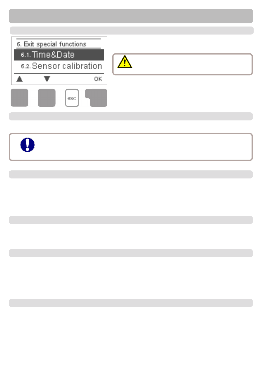
Special functions
6. - Special functions
Menu “6. Special functions” is used to set basic items
and expanded functions.
Other than the time all settings may only be
Caution
The menu is closed by pressing “esc” or selecting “Exit
special functions”.
6.1. - Pump menu
This menu contains the settings for 0-10V or PWM pump.
The power supply of HE pumps with 0-10V / PWM pumps can be connected to the corresponding relay (V1 -> R1, R2 -> V2), since the relays are
Caution
6.1.1. - Type of pump
The type of speed controlled pump must be entered here following the pumps data
sheet.
0-10V: Speed control of e.g. High efcency pumps by 0-10V signal.
PWM: Speed control of e.g. High efcency pumps by PWM signal.
switched on and off with the signal.
made by a specialist.
6.1.2. - Pump
In this menu, precongured proles for various pumps can be selected. Please note
that individual settings are still possible even when a prole has been selected.
6.1.3. - Output Signal
This menu determines the type of pump used: Solar pumps perform at their highest
power when the signal is also maxed, heating pump on the other hand are set to highest power wenn the control signal is at the lowest. Solar = normal, heating = Inverted.
Settings range: Normal, Inverted / Default setting: Normal
6.1.4. - 0-10V off / PWM off
This signal / this voltage is put out when the pump is switched off (Pumps that can
detect cable break need a minimum signal).
25
Page 26

Special functions
6.1.5. - 0-10V on / PWM on
This signal / this voltage is needed to turn the pump on at minimum speed / minimun
voltage.
Default setting: 90%
6.1.6. - 0-10V Max / PWM Max
This determines the output signal / the output voltage for the highest speed of the
pump, that is used e.g. during purging or manual operation.
6.1.7. - Show signal
Displays the set signal in text and a graphical diagram.
6.2. - Speed control R1 / R2
The settings in this menu are used to limit the speed of connected pumps.
6.2.1. - max. speed
The maximum speed of the pump is specied here. During the setting the pump runs
at the specied speed and the ow rate can be determined.
The indicated percentages are guide values that may vary to a greater or
Caution
lesser extent depending on the system, pump and pump stage.
6.2.2. - min. speed
The minimum speed of the pump at relay R1 is specied here. During the setting the
pump runs at the specied speed and the ow rate can be determined.
The indicated percentages are guide values that may vary to a greater or
lesser extent depending on the system, pump and pump stage.. 100% is
Caution
26
the maximum possible voltage/frequency of the controller.
Page 27

Special functions
6.5. - Relay functions 1
The additional functions explained here can be assigned to unused relays. Every additional function can only be used once. Pay special Caution to the technical data of the
relays („B.1. - Specications“ on page 5).
6.5.1. - Circulation
See „4.4.1. - Circulation“ on page 21
6.5.2. - Storage heating
Heat up the storage when necessary
6.5.2.1. - Storage heating
Switch heating on or off.
6.5.2.2. - Storage minimum temperature
If this temperature is undershot, storage heating is turned on even outside the set periods
for the storage heating.
6.5.2.2. - SH Setpoint Temperature
Taget temperature at thermostat sensor 1. Below this temperature, additional heating is switched on, till TH set + hysteresis is reached.
6.5.2.4. - SH hysteresis
Hysteresis of setpoint temperature for setpoint and minimum temperature.
6.5.2.5. - Periods
Storage heating activity times
Set the desired periods of time when the thermostat should be active. 3 periods can
be set per day, settings can also be copied to other days. Outside the set times the
thermostat is switched off.
27
Page 28

Special functions
6.5.3. - Storage stratication
Storage stratication switches a valve in the primary return ow depending on the temperature .
Temperature is measured in the primary circuit and optionally in the middle zone of the storage.
6.5.3.1. - Storage stratication
Switch stratication on or off.
6.5.3.2. - ∆T return storage
Temperature difference for stratication
If the temperature in the primary circuit exceeds the temperature difference set here, the valve
is switched to load the upper storage zone.
If the temperature drops below this temperature, the valve is switched off again.
When no storage sensor is connected, a temperature of 25°C is assumed.
6.5.4. - Parallel operation V1
The relais is switched on at the same time as the set relay V1 or V2.
6.5.4.1. - Parallel operation V1
See „6.5.4. - Parallel operation V1
6.5.4.2. - Delay
This menu determines how long after the start of R1 or R2 the parallel relay is switched
on.
6.5.4.3. - Followup time
This menu determines how long after the switch off of R1 or R2 the parallel relay is
switched off.
6.5.5. - Parallel operation V2
See „6.5.4. - Parallel operation V1
6.5.6. - Always on
Relay is permanently switched on.
6.6. - Relay 2
See „6.5. - Relay functions 1
6.7. - Relay 3
See „6.5. - Relay functions 1
28
Page 29

Special functions
6.8. - Signal V2
With this function the PMW/0-10V output 2 is used for an additional
high-efciency pump. If a pump function is activated (e.g. circulation), additional parameters
for pump settings V2 and V2 speed -control have to be set. For other functions (e.g. zone
valve) the output signal switch from 0 to 10 V. For other switching variants an additional relay
box can be used to switch a potential-free relay at this output.
Please note the technical information about the PMW/0-10V outputs
(„B.1 -. Specications“ on page 6).
6.8.1. - Signal V2
See „6.5. - Relay functions 1
6.9. - Pressure monitor
The relay is switched on when the pressure drops below set minimum or exceeds the
set maximum pressure.
6.9.1. - Pressure monitor
This menu is used to congure the system pressure montoring via direct sensor. As
soon as the set limits are exceeded, the relay is switched on.
6.9.2. - RPS1 / RPS2
Type of pressure sensor
This menu is used to determine the type of pressure sensor used.
Please note: If e.g. VFS1 is connected, RPS1 option is not shown.
6.9.3. - Pmin
Minimum pressure. If this value is undershot, an error message is displayed and the
relay is switched on.
6.9.4. - Pmax
Maximum pressure. If this value is exceeded, an error message is displayed and the
relay is switched on.
29
Page 30

Special functions
6.10. - Sensor calibration
Deviations in the temperature values displayed, for example due to cables which are to
long or sensors which are not positioned optimally, can be compensated for manually
here. The settings can be made for each individual sensor in steps of 0.5°C.
Settings are only necessary in special cases at the time of initial commissioning
Caution
6.11. - Commissioning
Starting the commissioning help guides you in the correct order through the basic settings necessary for commissioning, and provides brief descriptions of each parameter
in the display. Pressing the “esc” key takes you back to the previous value so you can
look at the selected setting again or adjust it if desired. Pressing the “esc” more than
once takes you back to the selection mode, thus cancelling the commissioning help.
(see also 5.1)
Caution
6.12. - Factory settings
All of the settings that have been made can be reset, thus returning the controller to its
delivery state.
by the specialist. Incorrect measurement values can lead to unpredictable errors.
May only be started by a specialist during commissioning! Observe the explanations for the the individual parameters in these instructions, and check
whether further settings are necessary for your application.
The entire parametrisation, analyses, etc. of the controller will be lost irrevocably.
Caution
The controller must then be commissioned once again.
6.13. - Time & Date
This menu is used to set the current time and date.
For proper functioning of the controller and statistics for the system data it is
essential for the time to be set accurately on the controller. Please note that the
Caution
clock continues to run for about 24 hours if the mains voltage is interrupted, and
after that has to be reset.
30
Page 31
Special functions
6.14. - Daylight saving time
When this function is active, the controller’s clock changes automatically to and from
DST (DST, Daylight Saving Time).
6.15. - Sleep mode
When this function is active, the controller’s backlight is automatically switched off
when no button has been pressed for 2 minutes.
If a message is waiting, the backlight is not switched off.
Caution
6.16. - Temperature unit
This menu changes the displayed temperature unit.
31
Page 32
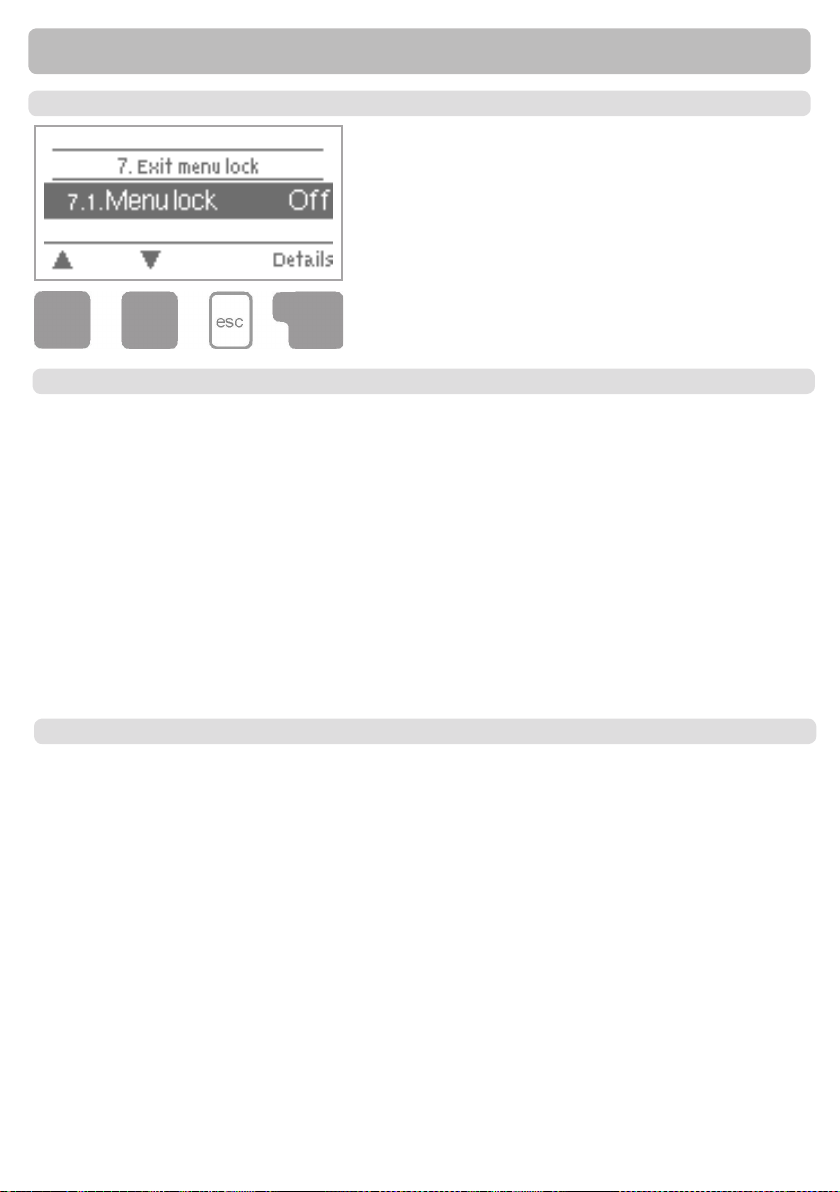
Menu lock
7. - Menu lock
Menu “7. Menu lock” can be used to secure the control-
ler against unintentional changing of the set values.
The menu is closed by pressing “esc” or selecting “Exit
menu lock”.
7.1. - Menu lock
The menus listed below remain completely accessible despite the menu
lock being activated, and can be used to make adjustments if necessary:
1. Measurement values
2. Analysis
3. Display mode
8. Menu lock
9. Service values
To lock the other menus, select “Menu lock on”.
To enable the menus again, select “Menu lock off”.
7.2. - Expert mode
This menu is used to switch between expert mode, in which all settings are available,
and simple mode, in which only the following menus are available:
1. Measurement values
2. Statistics
4.3 Ts et
4.4.1 Circulation mode
4.4.7 Circ. Periods
6.10 Time and Date
7. Menu lock without 7.1
9. Language
32
Page 33
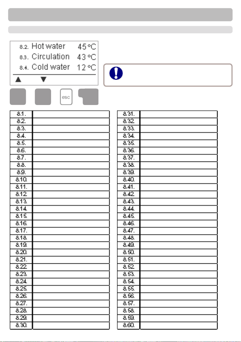
8. - Service values
Service values
The menu “8. Service values” can be used for remote
diagnosis by a specialist or the manufacturer in the
event of an error, etc.
Enter the values at the time when the
Caution
The menu can be closed at any time by pressing “esc”.
error occurs e.g. in the table.
33
Page 34
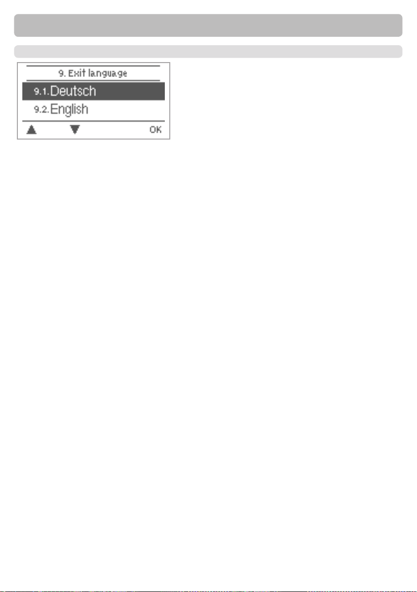
9. - Language
Language
Menu “9. Language” can be used to select the
language for the menu guidance. This is queried
automatically during initial commissioning. The
choice of languages may differ, however, depending on the device design. Language selection is not
available in every device design!
34
Page 35

Malfunctions
Z.1 Malfunctions with error messages
If the controller detects a malfunction, the red light ashes
and the warning symbol also appears in the display. If the
(LED ashes +
warning symbol)
error is no longer present, the warning symbol changes to an
info symbol and the red light no longer ashes.
To obtain more detailed information on the error, press the
key under the warning or info symbol.
Do not try to deal with this yourself.
Danger
Consult a specialist in the event of an error!
Possible error messages:
Sensor x defective
Time & date
Temperature < 50
Temperature > 70
Notes for the specialist:
Means that either the sensor, the sensor input at the
controller or the connecting cable is/was defective.
(Resistance table on page 5)
This display appears automatically after a mains
failure because the time&date have to be checked,
and reset if necessary.
The temperature at the optional sensor S3 fell below
50 °C.
This means that the primary temperature is too low,
so it could be possible to produce not enough hot
water
The temperature at the optional sensor S3 exceeded 70 °C.
This means that the primary temperature is too
high, so it is possible to have limescale in the
exchanger
35
Page 36
Malfunctions
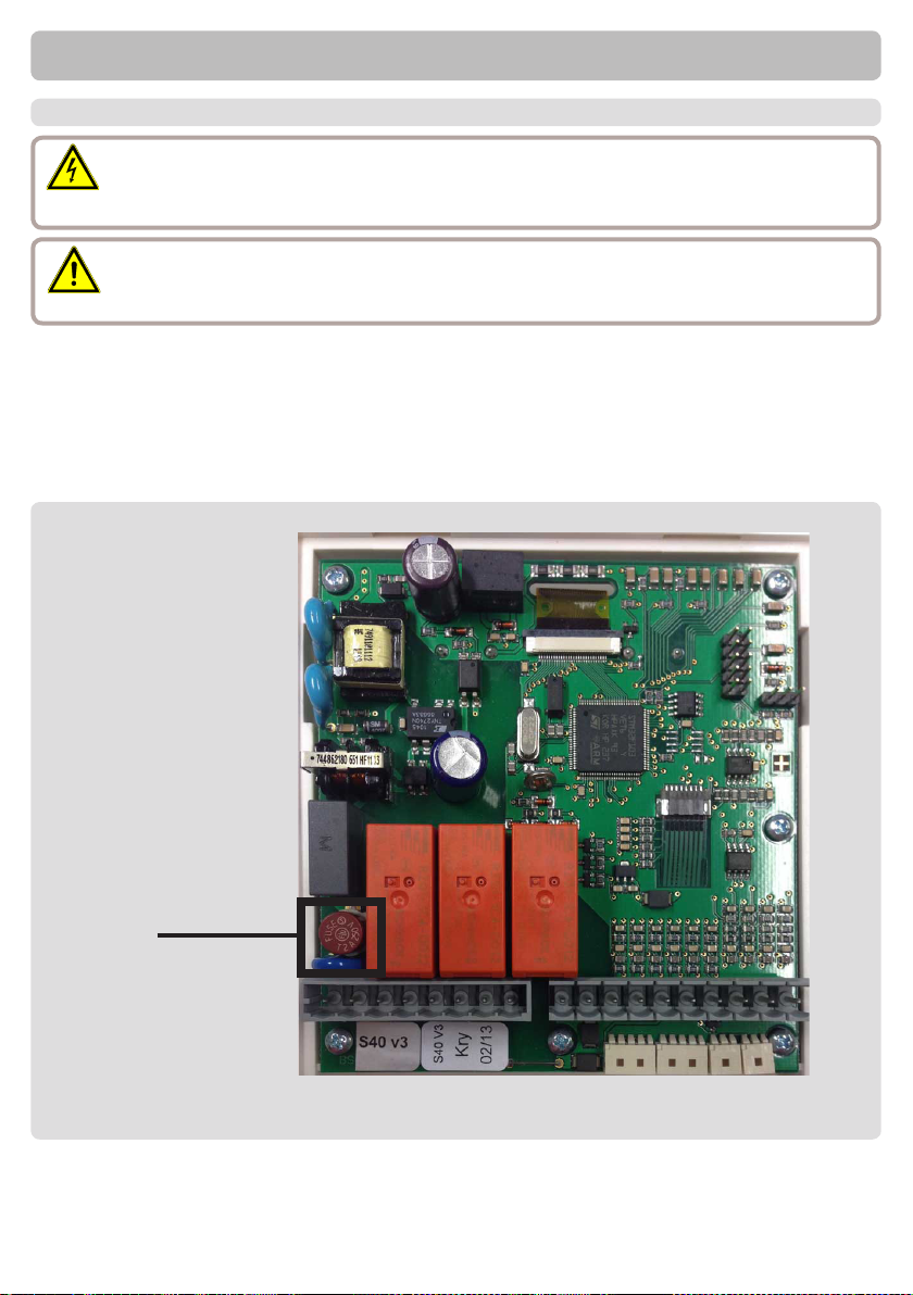
Z.2 Replacing the fuse
Repairs and maintenance may only be performed by a specialist. Before working
Danger
Danger
If the mains voltage is switched on and the controller still does not function or display
anything, then the internal device fuse may be defective. In that case, open the device as
described under 3.1, remove the old fuse and check it.
Exchange the defective fuse for a new one, locate the external source of the error (e.g.
pump) and exchange it. Then rst recommission the controller and check the function of the
switch outputs in manual mode as described under 9.2.
Fig.Z.2.1
on the unit, switch off the power supply and secure it against being switched on
again! Check for the absence of power!
Only use the supplied spare fuse or a fuse of the same design with the following
specications: T2A 250V
Fuse
36
Page 37
Maintenance
Z.3. Maintenance
In the course of the general annual maintenance of your heating system you should
also have the functions of the controller checked by a specialist and have the settings
Caution
Performing maintenance:
- Check the date and time (see 11.1)
- Assess/check plausibility of analyses (see 7.)
- Check the error memory (see 7.5)
- Verify/check plausibility of the current measurement values (see 6.)
- Check the switch outputs/consumers in manual mode (see 9.2)
- Poss. optimise the parameter settings
optimised if necessary.
37
Page 38

Hydraulic variant set:
Commissioned on:
Commissioned by:
Notes:
Final declaration:
Although these instructions have been created with the greatest possible care,
the possibility of incorrect or incomplete information cannot be excluded. Subject
as a basic principle to errors and technical changes.
38
 Loading...