

Austria Email eco clever 80, eco clever 100, eco clever 120, eco clever 150 Operating And Installation Instructions
Operating and Installation
Instructions
ECO CLEVER
Please forward this on to the user!
Id. no.: 242440-7
Pressure resistant electric water heater
80 - 100 - 120 - 150 Litres
2
Id. no.: 242440-7
DEAR CUSTOMER!
You have taken the decision to purchase a water heater with electrical storage
system from our company.
We would like to thank you for your condence!
You will receive an elegant device built to state-of-the-art technical specications, which complies with all applicable regulations. The enamelling, which has
been highly developed through continuous research, as well as ongoing quality
control during production, endows our hot water storage tanks with technical
characteristics you will always appreciate. The environmentally friendly CFCfree insulating foam, as well as the control system used, ensures an extraordinarily low standby energy consumption. For the sake of the environment, the
ARA (Junk Recycling Austria AG) licence enables you to have the packaging of
your device professionally disposed of.
The installation and initial commissioning may only be carried out by a licensed
installation company in accordance with these instructions.
Within this small brochure you will nd all important information for the correct
installation and operation. It is still important to have your licensed installer explain the function of the device to you and demonstrate its operation. Of course,
our company is also glad to be at your disposal through the Customer Services
and Sales Departments for any advice you may require.
We hope that you will enjoy your electrical storage system.
Did you know that products from Austria Email AG offer outstanding energy
efciency?
To nd out more, visit www.topprodukte.at

Id. no.: 242440-7
3
Safety instructions ............................................................................................... 4
Function ................................................................................................................ 5
Hot water requirement ........................................................................................5
Saving Energy ....................................................................................................... 5
Standby energy consumption ............................................................................. 6
Operating the ECO CLEVER control system (LCD version) ............................. 6
Clever mode ..................................................................................................................8
Manual mode ................................................................................................................ 9
Legionella protection circuit .......................................................................................... 9
Child lock ...................................................................................................................... 9
Display backlighting ...................................................................................................... 9
Error codes ..................................................................................................................10
Troubleshooting ...........................................................................................................11
Control unit ..................................................................................................................12
Operating Requirements .................................................................................... 13
Installation and Safety Information ................................................................... 13
Dimensions Sketch ............................................................................................. 15
Product Data ErP ................................................................................................16
Domestic Hot Water Side Connection (pressure resistant) ............................16
Electrical Connection .........................................................................................18
General information .....................................................................................................18
Connection diagram ....................................................................................................18
Initial Commissioning ......................................................................................... 19
Decommissioning, Draining ............................................................................... 19
Inspection, Maintenance, Servicing .................................................................. 20
Malfunctions ........................................................................................................ 20
Guarantee, Warranty and Product Liability ......................................................21

4
Id. no.: 242440-7
SAFETY INSTRUCTIONS
General
• This storage tank can be used by children eight years old and older as well as by persons with reduced physical, sensory or mental capabilities or who lack experience and knowledge if they are
supervised or if they have been trained with regard to the safe use of the storage tank and understand the resulting risks. Children may not play with the storage tank or its packaging. Cleaning and
user maintenance may not be performed by children without supervision.
• The storage tank may only be installed and operated as described in this manual or the associated
technical information. Any other use is not in accordance with instructions and is therefore impermissible.
• A defective storage tank may not continue to be operated.
• There is a risk of scalding from hot water or hot components (e.g. ttings, hot water outlet pipe,
etc.).
• When using an electric immersion heater, proper corrosion protection is to be ensured.
Installation and commissioning
• Installation and commissioning may only be performed by qualied specialised personnel who
therefore assume the responsibility for proper assembly in accordance with the applicable laws,
standards and guidelines.
• The storage tank is mounted to a sufcient load-bearing wall using a wall mount (note the total
weight of the lled storage tank) or is placed on a at horizontal surface (install supporting feet
depending on the type). Ensure that the subsurface at the installation location has a sufcient
load-bearing capacity.
• The storage tank may only be set up in dry, frost-protected spaces. The storage tank is to be com-
pletely emptied if there is a risk of freezing.
• The rated pressure specied on the nameplate may not be exceeded.
• When installing the storage tank, a possible water leak is to be considered and a corresponding
collection container (including drain) is to be installed in a drainage object.
• Following commissioning, the storage tank and all connections are to be checked for leak tightness.
Electrical Connection
• Only qualied specialised personnel may connect the storage tank to xed lines while observing
the relevant professional standards and laws.
• A ground fault circuit interrupter with a trip current of I∆n ≤ 30mA must be installed upstream from
the electrical circuit.
• Before working on the storage tank, the latter is to be de-energised, checked for the absence of
voltage and secured against being switched on again.
• If a connection cable is damaged, immediately disconnect the power supply (circuit breaker) and
call a professional!
• Connection cables may not be extended or cut through in any way.
Maintenance
• Maintenance, cleaning and any necessary repair or service work may only be performed by special-
ised personnel who are qualied for this purpose.
• Never try to x errors and faults yourself.
• Necessary service and maintenance intervals are to be observed in accordance with these operating and assembly instructions.
Id. no.: 242440-7
5
FUNCTION
The domestic water stored in the enamelled internal boiler is heated up by the electrical heating element.
The user can preselect the desired temperature on the operating panel. The heating is independently
switched on during heating-up process by the control and switched off again after reaching the desired
stored water temperature.
If the water temperature drops, for instance due to water abstraction or natural cooling (the high-quality
CFC-free polyurethane foam insulation keeps it as low as possible), the device switches itself back on
again until the stored water temperature is reached.
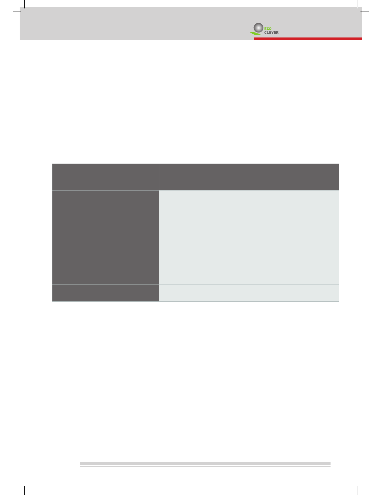
HOT WATER REQUIREMENT
Hot water consumption in the household is dependent upon the number of people, the sanitary ttings in
the at or house, the insulation, the plumbing and the individual habits of the user.
The following table provides a few standard values for consumption.
The temperature of the cold water required for mixing for the stated hot water temperature was assumed
to be approx. 12 °C.
SAVING ENERGY
Our electrical storage system is a real energy saver due to its high quality, CFC-free polyurethane foam
insulation and its built-in control system.
Low storage water temperatures turn out to be particularly economical.
That is why the level of the temperature adjustment should only be set in accordance with the actual hot
water requirements. This helps save energy and reduces limescale build-up within the container.
Hot water require-
ments in litres
Required stored water capacity in
litres
at 37°C at 55°C with 80°C with 60°C
Full bath 150 - 180 55 - 66 78 - 94
Shower 30 - 50 11 - 18 16 - 26
Hand wash 3 - 6 1 - 2 1.6 - 3.1
Hair wash (short hair) 6 - 12 3 - 4.4 4.2 - 6.3
Hair wash (long hair) 10 - 18 3.7 - 6.6 5.2 - 9.4
Bidet utilisation 12 - 15 4.4 - 5.5 6.3 - 7.8
Washing dishes
for 2 people per day 16 10 14
for 3 people per day 20 12.5 18
for 4 people per day 24 15.2 21.5
Housework per bucket of cleaning
water
10 6.3 9
6
Id. no.: 242440-7
STANDBY ENERGY CONSUMPTION
If a water heater is heated up and no water is released for a long time after the heating process, a cooling
of the stored water via the surface of the device, albeit gradual but continuous, will be the result.
The intensity and speed of his cooling off will vary according to the construction type of the device, the
size of the device, thickness and quality of the container insulation.
This behaviour is measured at a stored water temperature of 65°C over a period of 24 hours and the
amount of energy required to keep the water at a constant temperature throughout this period is measured in kWh.
Nominal capacity in litres 80 100 120 150
Standby energy consumption
kWh/24h
0.95 1.08 1.23 1.45
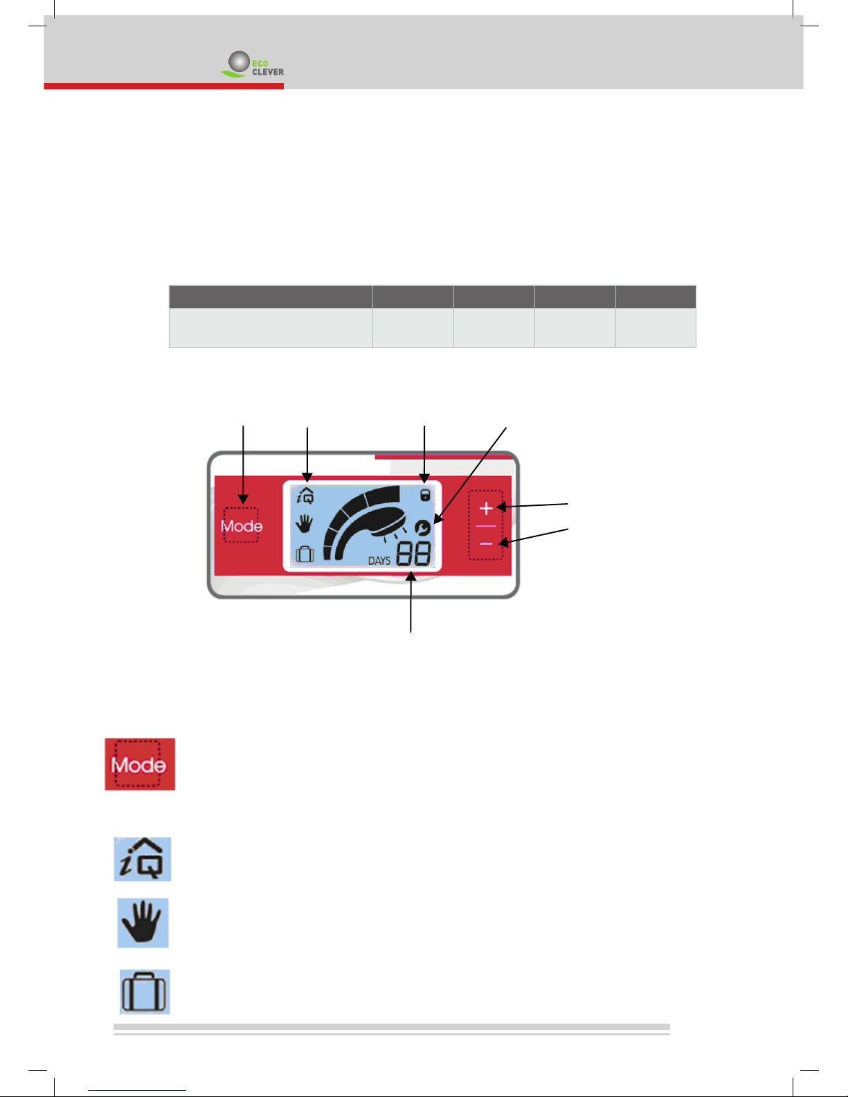
OPERATING THE ECO CLEVER CONTROL SYSTEM (LCD VERSION)
Operation
The LCD controller has 3 push buttons which can be used to select the desired operating
mode.
This button is used used to select between the 3 different operating modes.
Press the Mode button once or multiple times to select the desired mode – the desired function appears on the display.
By pressing and holding down this button for at least 3 seconds, the device can be switched
on or off.
Clever
This mode is used for saving energy effectively. The controller adjusts to the user’s behaviour
and heats up the water only when it is needed.
Manual
In this mode the hot water temperature is constantly adjusted to the comfort level which is
selected.
Holiday / Standby
In this mode the tank does not heat-up the water over a set period, unless the water temperature falls below 7°C.
mode-selecting operation mode
child lock
maintenance and error indicator
buttons to select
level of comfort and
holiday days
holiday days or
error code
Id. no.: 242440-7
7
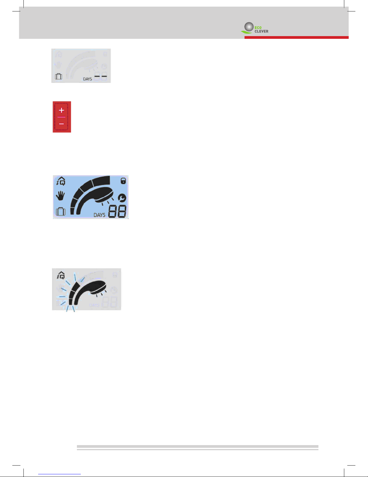
When holiday mode is selected, the following image appears in the display.
You can set the required days by pressing the [+] or [-] button. Pressing the [+] or [-] button for
longer allows quicker selection of the days.
The maximum number of days is 99.
The controller automatically switches itself to the previously selected mode after the set days
have elapsed.
The level of comfort and the number of holiday days can be set using these buttons.
If the tank is correctly installed and lled completely with water, the electrical connection can
be made and the electricity switched on.
As soon as an electric current ows, all segments of the display are visible for a few seconds.
After the display test, the controller automatically switches to the “Clever” – Level “5” operating mode.
A ashing shower symbol indicates that the water is being heated-up.
8
Id. no.: 242440-7
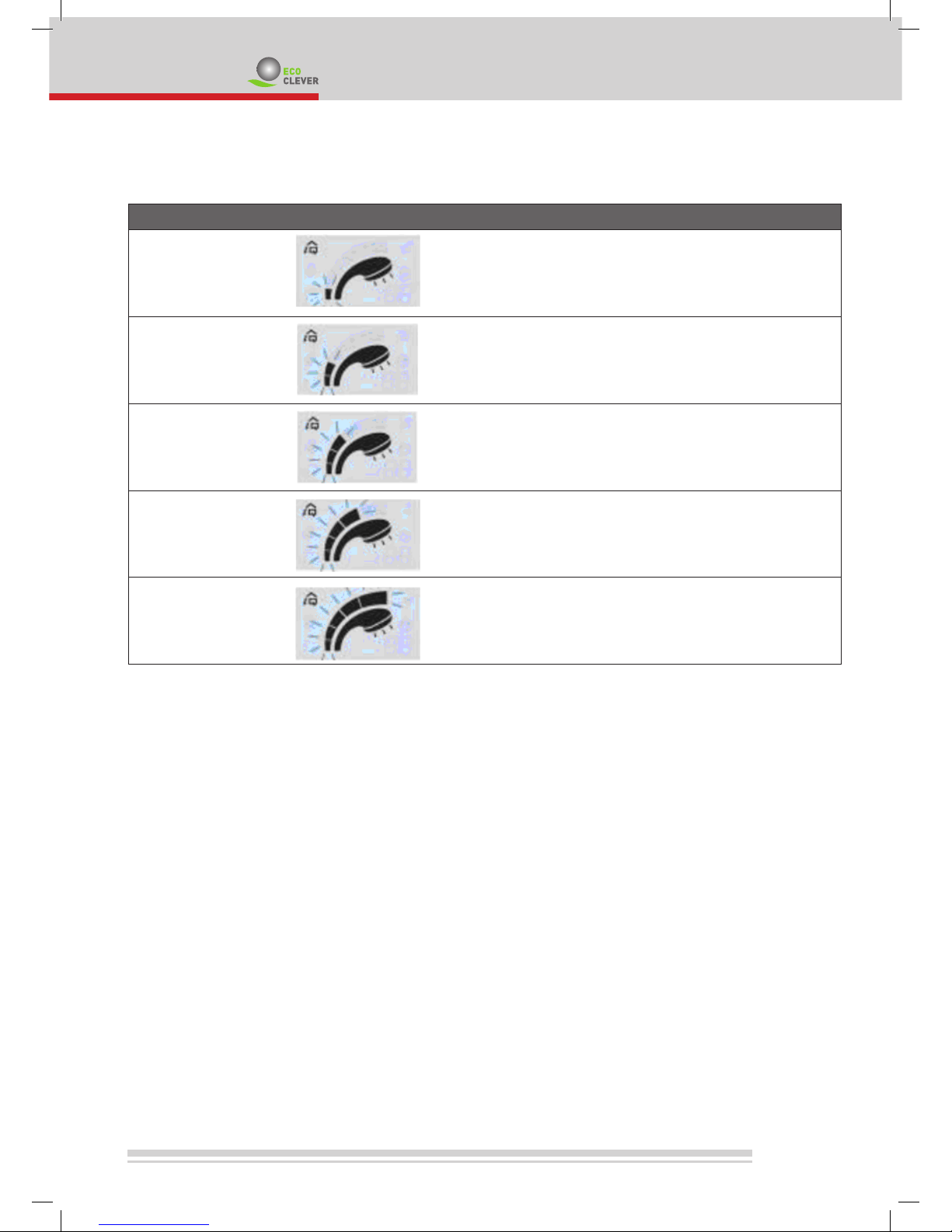
Clever mode
The different comfort levels can be set by pressing the [+] or [-] button.
Comfort level Selection Comfort level Energy saving
1 -- ++
2 - +
3 +
recommended;
standard setting
+
4 ++ -
5 +++ --
Comfort level “3” complies with the requirements of prEN 15440 and corresponds to 80% of the possible
hot water content.
3 seconds after you have selected the level, the level is set and the heat content is displayed.
The hot water temperature can change since this is adjusted to the respective user behaviour.
 Loading...