

Page 1
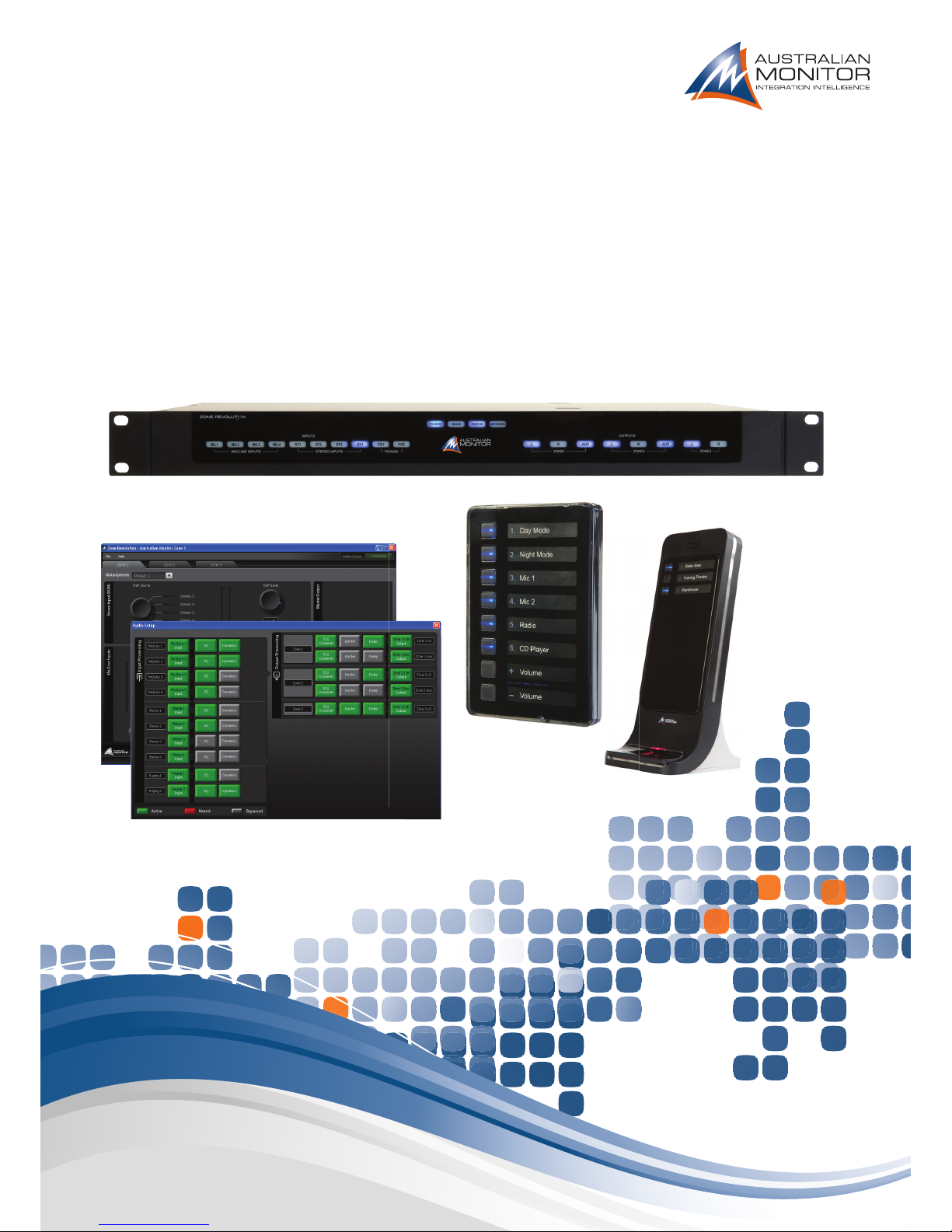
Zone Revolution
Quick Start Manual
Page 2

Read these instructions.1.
Keep these instructions.2.
Heed all warnings.3.
Follow all instructions.4.
Do not use this apparatus near water.5.
Clean only with dry cloth.6.
Do not block any ventilation openings. Install in accordance with the 7.
manufacturer’s instructions.
Do not install near any heat sources such as radiators, heat registers, 8.
stoves, or other apparatus (including amplifiers) that produce heat.
Do not defeat the safety purpose of the polarized or grounding-type plug. 9.
A polarized plug has two blades with one wider than the other.
A grounding type plug has two blades and a third grounding prong.
The wide blade or the third prong are provided for your safety. If the
provided plug does not fit into your outlet, consult an electrician for
replacement of the obsolete outlet.
Protect the power cord from being walked on or pinched particularly 10.
at plugs, convenience receptacles, and the point where they exit from
the apparatus.
Only use attachments/accessories specified by the manufacturer.11.
Use only with the cart, stand, tripod, bracket, or table specified by the 12.
manufacturer, or sold with the apparatus. When a cart is used, use caution
when moving the cart/apparatus combination to avoid injury from tip-over.
Unplug this apparatus during lightning storms or when 13.
unused for long periods of time.
Refer all servicing to qualified service personnel. 14.
Servicing is required when the apparatus has been
damaged in any way, such as power-supply cord or plug
is damaged, liquid has been spilled or objects have fallen into the
apparatus, the apparatus has been exposed to rain or moisture, does
not operate normally, or has been dropped.
This appliance shall not be exposed to dripping or splashing water and 15.
that no object fi lled with liquid such as vases shall be placed on the
apparatus.
Connect the equipment to an appropriate wall outlet that is readily 16.
accessible.
The mains plug is used as the disconnect device and shall remain 17.
readily accessible. If the mains plug is not readily accessible due to
mounting in a 19” rack, then the mains plug for the entire rack must
be readily accessible.
WARNING:18. To reduce the risk of fi re or electric shock, do not expose this
apparatus to rain or moisture.
An appliance with a protective earth terminal should be connected to a 19.
mains outlet with a protective earth connection.
LISEZ ces instructions.1.
Tenez ces instructions.2.
Notez tous les avertissements.3.
Suivez toutes les avertissements.4.
N’utilisez pas ce produit près de l’eau (la piscine, la plage, le lac, etc.).5.
Nettoyez seulement avec une étoffe sèche.6.
Ne bloquez aucuns troux de ventilation. Installez en accord avec 7.
les instructions du manufacturier.
N’installez près aucunes sources de chaleur comme radiateurs, registres 8.
de chaleur, fours ou les autres équipements (y compris amplifi cateurs)
qui produisent la chaleur.
Ne défaites pas le but de sécurité de la fi che polarisée ou base-type. 9.
Une fi che polarisée a deux tranchants avec un plus large que l’autre.
Une fi che de base type a deux a deux tranchants et une troisième
pointe de base, le tranchant large ou la troisième pointe est fourni
pour votre sécurité. Si la fi che donnée ne conforme pas votre prise
de contact, consultez un électricien pour remplacement de la prise
de contact obsolète.
Protegez le cordon de secteur contre être marchée dessus ou pincez 10.
en particulier aux fi ches, aux douilles de convenance, et au point où ils
sortent de l’appareil.
Seulement utilisez attachements/accessoires spécifi és par le 11.
manufacturier.
Utilisez seulement avec un chariot, un stand, un trépied, un support 12.
ou une table indiquée par le manufacturier, ou vendue avec l’appareil.
Quand un chariot est utilisé, faites attention en déplaçant la combinaison
d’appareil/chariot pour éviter de se déséquilibrer.
Arrachez la fi che du dispositif durant éclair et orage ou 13.
quand pas utilisé pour longues périodes de temps.
Référez au personnel qualifi é de service pour toutes 14.
réparations. La réparation est donnée quand le système
a été endommagé à n’importe façon, par exemple un fi l ou une fi che
endommagé(e) de la source d’alimentation. Avoir été exposé à pluie ou
humidité, n’opère pas normalement, ou avoir été tombé.
L’appareil ne doit pas être exposé aux écoulements ou aux éclaboussures 15.
et aucun objet ne contenant de liquide, tel qu’un vase, ne doit être placé
sur l’objet.
Branchez l’appareil à une source appropriée et faire que la prise à 16.
débrancher soit facilement accessible.
La prise du secteur ne doit pas être obstruée ou doit être facilement 17.
accessible pendant son utilisation. Pour être complètement déconnecté
de l’alimentation d’entrée, la prise doit être débranchée du secteur.
AVERTISSEMENT: 18. Pour éviter le risque d’incendie ou de chocs électriques,
ne pas exposer cet appareil à la pluie ou à l’humidité.
Un appareil avec la borne de terre de protection doit être connecté au 19.
secteur avec la connexiion de terre de protection.
IMPORTANT SAFETY INFORMATION PRÉCAUTIONS DURANT UTILISATION
Page 3
Zone Revolution is a stereo zoning solution for the bar and club
market, providing a combination of mono and stereo outputs with
the fl exibility to handle most foreground and background processing
applications. Larger stereo installations may be achieved by linking
two Zone Revolution units together. Zone Revolution has the
comprehensive processing you would expect from a state of the
art DSP processor. Zone Revolution also offers multi bus paging
when used with the ergonomic and visually stunning ICON paging
microphones. Zone Revolution supports ICON-CP wall panels as
well as 3rd party network control which can be easily confi gured
to recall global presets, select signal sources, control levels as well
as a host of other parameters. An optional CobraNet card is also
available for integration with larger articulated systems.
Box Contents
Zone Revolution
Software CD
Quick Start Manual
Revision 1.0 February 2011.
Copyright 2011
INTRODUCTION 1
FRONT PANEL 2
REAR PANEL 3
SETUP 4
ADVANCED SETTINGS/AUDIO SETUP 5
ICON-CP CONTROL PANELS/PANEL SETUP 8
MASTER OVERRIDE/GLOBAL PRESETS 9
CONTROL PANEL OPTIONS 10
DIMENSIONS 11
SPECIFICATIONS 12
WARNING!
TO PREVENT FIRE OR SHOCK HAZARD, DO NOT USE THE PLUG WITH
AN EXTENSION CORD, RECEPTACLE OR OTHER OUTLET UNLESS THE BLADES
CAN BE FULLY INSERTED TO PREVENT BLADE EXPOSURE.
TO REDUCE THE RISK OF FIRE OR ELECTRIC SHOCK, DO NOT EXPOSE
THIS APPLIANCE TO RAIN OR MOISTURE.
TO PREVENT ELECTRICAL SHOCK, MATCH WIDE BLADE PLUG TO WIDE SLOT, FULLY INSERT.
CAUTION
RISK OF ELECTRIC SHOCK
DO NOT OPEN
The lightning fl ash with arrowhead symbol,
within an equilateral triangle, is intended
to alert the user to the presence of
uninsulated “dangerous voltage” within
the product’s enclosure that may be of
suffi cient magnitude to constitute a risk
of electric shock to persons.
WARNING: TO REDUCE THE RISK
OF ELECTRIC SHOCK, DO NOT
REMOVE COVER (OR BACK).
NO USER SERVICEABLE PARTS INSIDE.
REFER SERVICING TO QUALIFIED
SERVICE PERSONNEL.
The exclamation point within an equilateral
triangle is intended to alert the user to
the presence of important operating and
maintenance (servicing) instructions in the
literature accompanying the appliance.
Rating plate and caution marking are marked on the back enclosure of the apparatus
ZONE REVOLUTION
PAGE 1
ZONE REVOLUTION QUICKSTART MANUAL
INTRODUCTION AND CONTENTS
Page 4
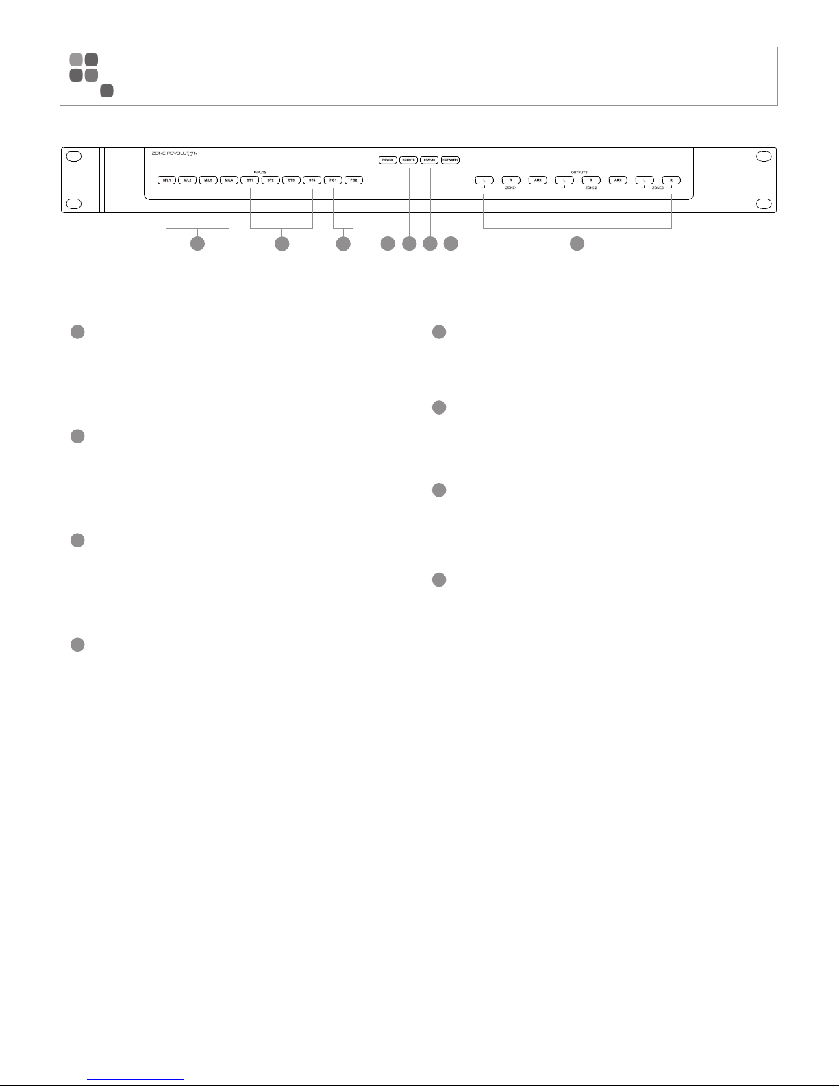
1
Mic/Line 1-4
Blue indicates signal presence
Pink indicates approaching signal clip
Red indicates signal clip
2
Stereo 1-4
Blue indicates signal presence
Pink indicates approaching signal clip
Red indicates signal clip
3
Page Inputs 1-2
Blue indicates signal
presence
Pink indicates approaching signal clip
Red indicates signal clip
4
Power Indicator
Blue indicates mains power is present
5
RS485 Indicator
Blue indicates remote panels are present, the light
will fl ash when data is passed across this network
6
Status Indicator
Blue indicates the system is running
Red indicates the system is busy or has an error
7
Network Indicator
Blue indicates a network device is connected.
The light will fl ash each time a packet is passed
across this network
8
Zone Outputs
Blue indicates signal presence
Pink indicates approaching signal clip
Red indicates signal clip
PAGE 2
ZONE REVOLUTION QUICKSTART MANUAL
FRONT PANEL
1 4 5 6 7 8
23
Page 5
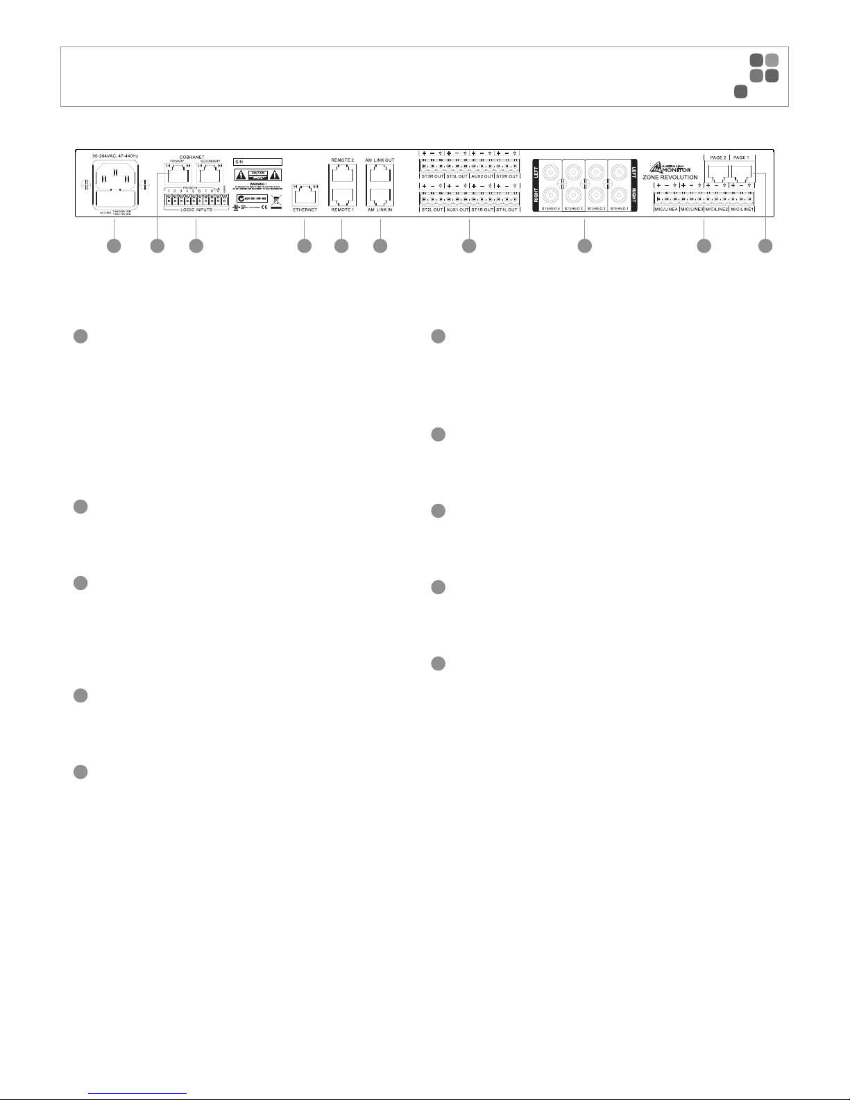
1
IEC Mains Socket
This is a standard 3-pin IEC socket (IEC3020-C14). It accepts a standard IEC
mains cable, provided. The fuse draw contains the mains fuse and a spare.
The mains fuse is a time lag (slow blow) HRC 20mm x 5mm fuse, the fuse
ratings are:
230V : 0.6A S/B
115V : 1.2A S/B
The power supply is universal so it will accept voltages from 90-264V.
2
Optional Cobranet Card
Optional module available to enable Cobranet connectivity. This card will
parallel all inputs and outputs to be available on Cobranet.
3
Override and Preset Contact Closures
Pins 1-8 are trigger pins for the global presets. When any one of these pins
are momentarily joined to the COM pin that preset will be triggered.
Pin O/Ride is a trigger for the external Master Override function. This can be
set up within the software.
4
Ethernet Port
The Ethernet port is a standard RJ45 port which allows the user control with
the supplied GUI or a third party control system.
5
RS485 Ports
The RS485 ports allow for the connection of ICON-CP control panels using
standard pin to pin wiring. Use of straight through CAT5 cable is suggested to
keep the RS485 line twisted for optimal noise rejection
6
AM Linking Ports
The AM Linking ports allow multiple Zone Revolution units to be linked for
expansion purposes.
This feature is for future use.
7
Balanced Zone Outputs
Balanced outputs for each zone are supplied on Euroblock connectors for easy
termination. These are a standard 5.08mm pitch.
8
Unbalanced Stereo Inputs
Unbalanced RCA connections are supplied for all stereo inputs. They are in
stereo pairs as the unit supports stereo straight through.
9
Balanced Mic/Line Inputs
Mic/Line inputs are supplied on Euroblock connectors for easy termination.
These are also a standard 5.08mm pitch.
10
Page Ports
The Page Ports allow for the connection of ICON Paging Stations. ICON Paging
Stations use standard pin to pin wiring. Use of straight through CAT5 cable is
suggested to keep the RS485 & Audio lines twisted for optimal noise rejection
PAGE 3
ZONE REVOLUTION QUICKSTART MANUAL
REAR PANEL
1 3 4 5 6 7 8 92 10
Page 6
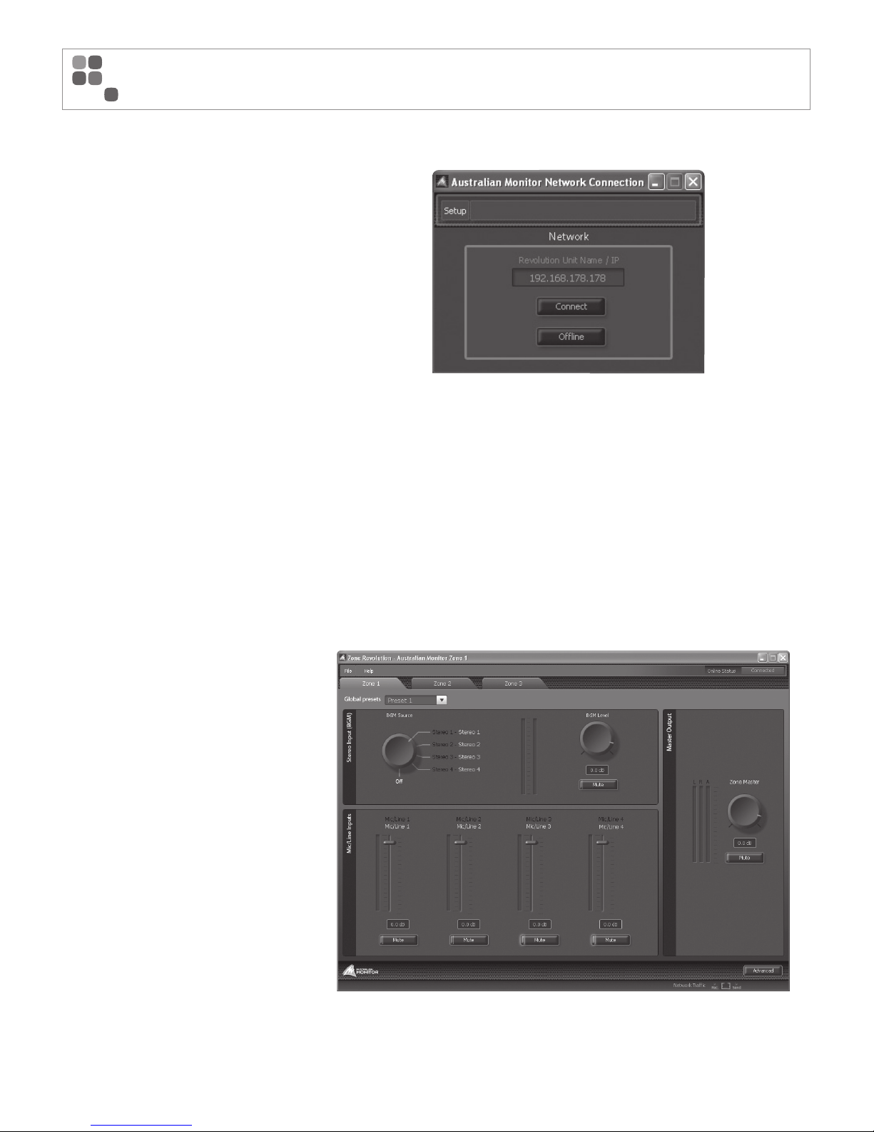
Network Connection:
When the Zone Revolution software is run for the fi rst
time a default connection page is launched. By clicking
File > Settings it is possible to make this page not
appear and have the software simply connect to the
last known good connection. This allows the installer to
have the software confi gured and connect automatically
as the PC starts up.
The initial connection page also allows the user to
update fi rmware and change the IP address within the
Zone Revolution hardware. This can all be done from
the Setup drop menu within the title bar.
All Zone Revolution units have a default IP address of
192.168.178.178.
Connection For the First Time:
It is suggested that when connecting to the
Zone Revolution for the fi rst time that a crossover cable
is used straight between the unit and your PC. You
will then need to change your network adapter to
have an IP of 192.168.178.170 with a subnet of
255.255.255.0. Then all you will need to do is open
the Zone Rev software and connect. Once you have
connected for the fi rst time you can set the units
IP address or change it to DHCP.
Zone Control Page:
The main page of the Zone Revolution software allows
the user to adjust all routing for a particular zone.
In terms of DSP the zone routing page is after the
input source processing but before the zone’s output
processing. All inputs within the Zone Revolution are
available on all outputs. This page gives the user
access to adjust basic functions such as volume,
panning and mute controls.
PAGE 4
ZONE REVOLUTION QUICKSTART MANUAL
SETUP
Page 7
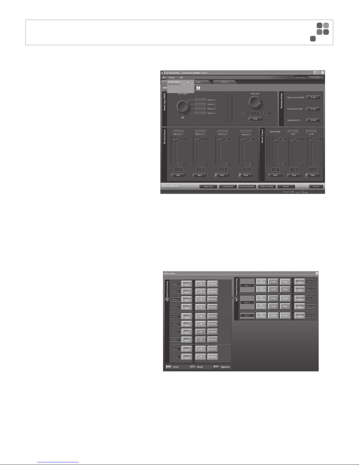
Advanced Mode:
In the bottom right hand corner of the Zone Revolution
software there is an “Advanced” button. The features
allow the contractor to adjust DSP processing, min and
max volumes and other advanced features. This section
of the software can be password protected against
inappropriate access. To set a new password click
“Settings > Set Password”.
Out of the box the Zone Revolution does not have a
password set. A password can be added by simply
typing it into the new password box and a pop up will
inform you that the change was successful. To remove
a password simply type in the “Old password” and
then leave the new password box blank, a prompt
should appear telling you that the password has been
removed.
Advanced Mode Set Up:
At the base of the advanced mode screen, there are
four buttons added to the GUI. These allow set up of
functions relating to the Audio Setup, Control Panels,
Master Override and Presets.
Audio Setup
The Audio Setup page allows the user to control all DSP
functions of each input and output signal. The page
also allows the user to see the signal fl ow from input
to output. Within this screen there are small signal
indicators for each input and output. This page makes a
great trouble shooting guide to see signal entering and
leaving the DSP functions.
PAGE 5
ZONE REVOLUTION QUICKSTART MANUAL
ADVANCED SETTINGS/AUDIO SETUP
Page 8
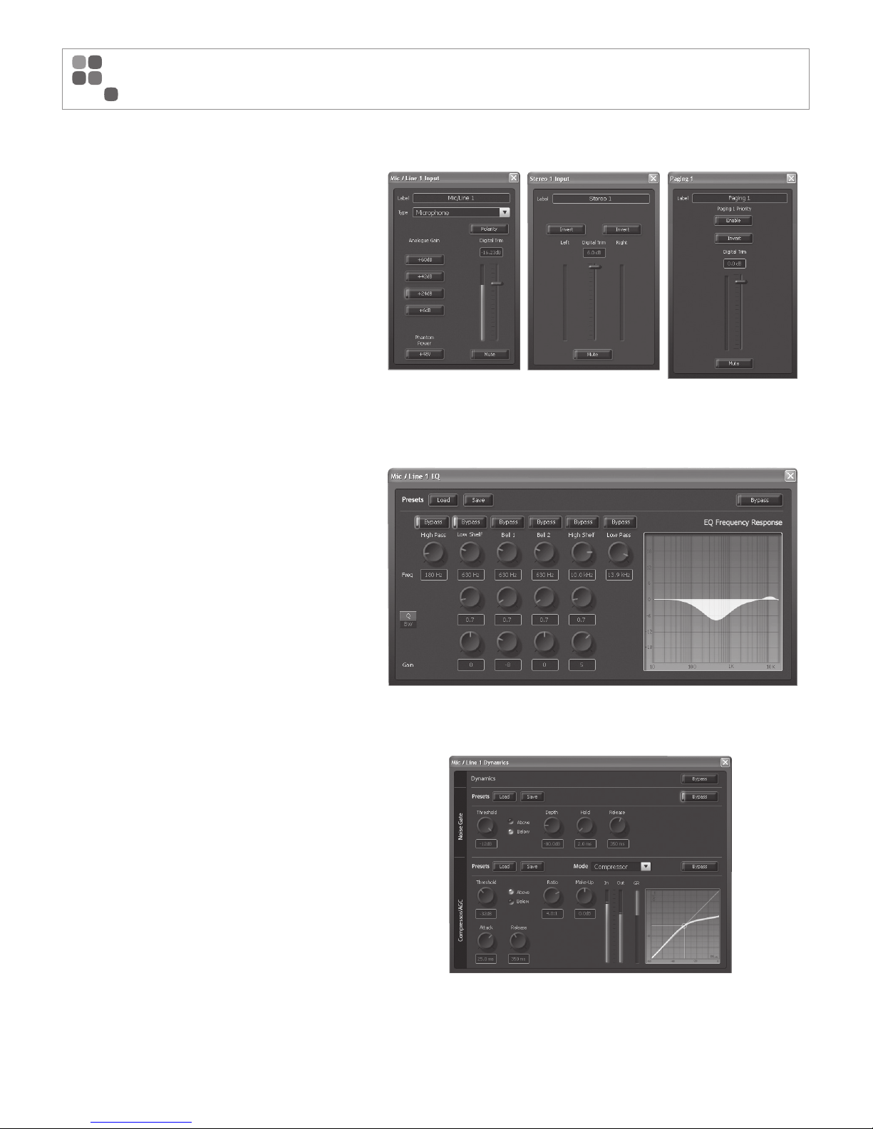
Inputs
Each Mic/Line input can be confi gured as either
Microphone level or Line level. The user has options
such as polarity, analog gain sensitivity and digital trim.
Each Mic/Line input also supports full +48V phantom
power.
The Analog gain steps are gain adjustments in the
Analog domain where as the fader represents control
of the DSP domain.
The stereo inputs follow most of the same functions
that relate to line level inputs on the mic/line input.
The page inputs provide a single digital trim fader,
phase invert and mute buttons. Paging Input 1 also
provides a priority enable feature than when enabled
provides priority paging to this input.
Input EQ
Each input has comprehensive EQ functions: high and low
pass fi lters, high and low shelf and two parametric fi lters.
Each EQ can be adjusted in either Q or BW. All processing
is represented on the EQ frequency response graph on the
right hand side of that window.
You can save processing preset fi les for each block from
the EQ onwards. This allows a user to have some preset
EQ fi les such as “Gooseneck Microphone” or “Lapel EQ”.
Dynamics
The dynamics page allows the user to adjust a Noise
Gate for each input and also a Compressor or AGC
for each input. Every block that contains two or more
processing options has an overall “bypass” in red and a
per function “bypass” in blue.
PAGE 6
ZONE REVOLUTION QUICKSTART MANUAL
AUDIO SETUP CONTINUED
Page 9
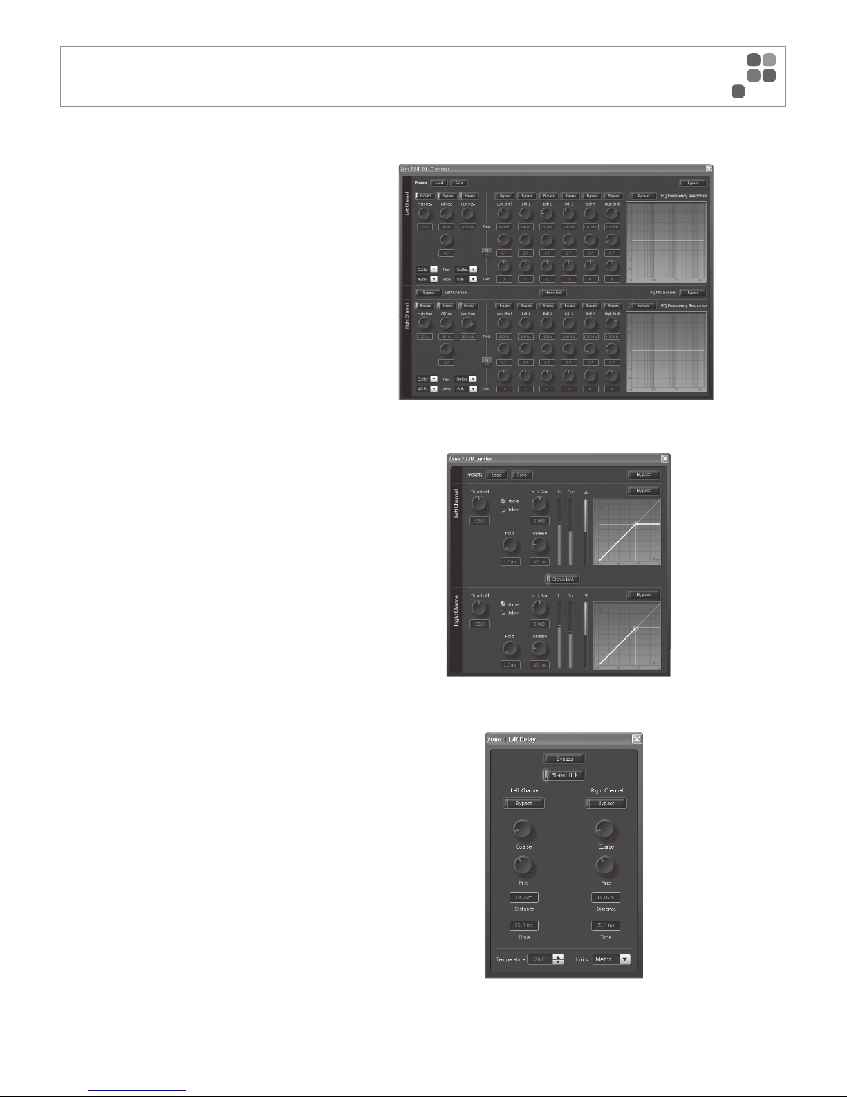
EQ/Crossover
The EQ/Crossover block allows you to set up a
crossover and apply equalisation to each output.
All stereo functions have a stereo link button. This will
copy all functions from the left to the right in stereo
applications.
Crossover
The crossover section of each output allows the
user to set up a high pass, low pass and all pass
fi lter. Each high and low pass fi lter can be either
Butterworth, Linkwitz Riley or Bessel and can have
slopes up to 48dB per octave.
EQ
Each output also offers comprehensive EQ
functions. These allow a user to confi gure a
low and high shelf and 4 parametric fi lters.
Limiter
Each output features a fully optioned limiter with
stereo link function on stereo zones.
Delay
Each output has a delay for both the left and the right
channel. It has coarse and also fi ne control for setting
in precise delays. The user can also simply type in the
required distance or time. At the bottom of the delay
section a user can also adjust temperature for even
more precise adjustment of delays and also switch the
measurements between metric and imperial.
PAGE 7
ZONE REVOLUTION QUICKSTART MANUAL
AUDIO SETUP CONTINUED
Page 10
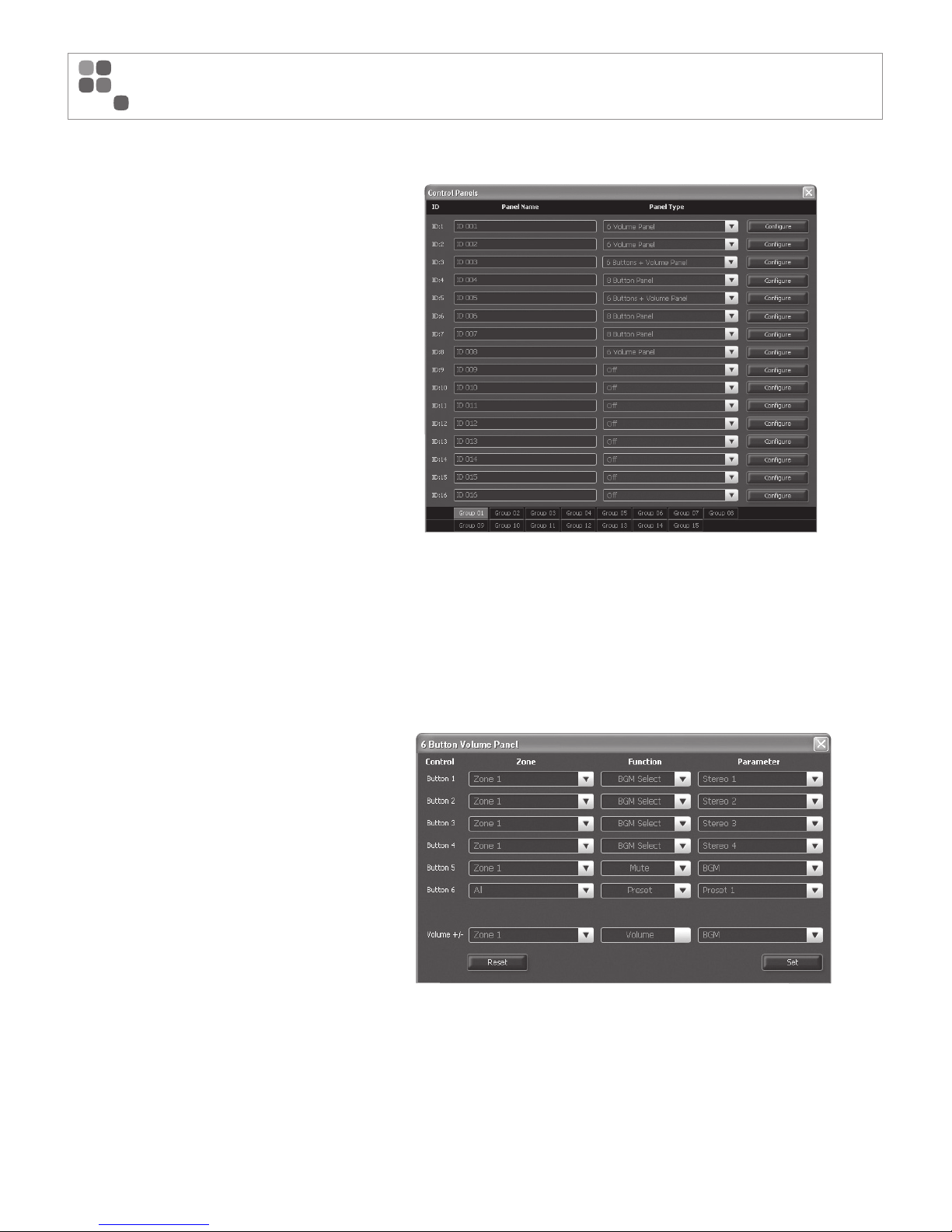
ICON-CP Control Panels:
The control panel screen allows the user to set up all
control panels connected to their system. Each remote
panel can be renamed for easy identifi cation.
Once a name is given to a panel the user can specify
its type; options are 6 Volume, 6 buttons + volume
or 8 buttons.
Panel Set Up:
From the “Confi gure” screen the user can set up the
zone to be controlled and what parameter the control
panel affects.
PAGE 8
ZONE REVOLUTION QUICKSTART MANUAL
ICON-CP CONTROL PANELS/PANEL SET UP
Page 11
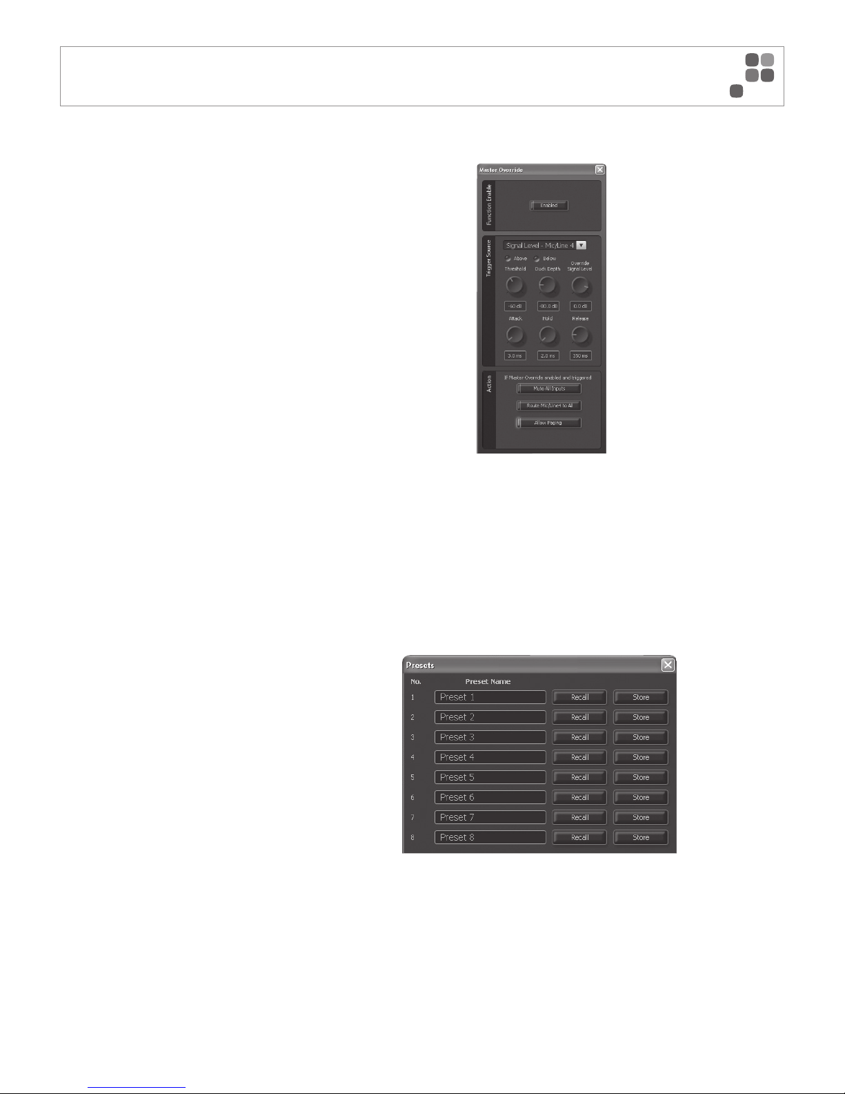
Global Presets:
The presets window allows the user to defi ne up to 8
global presets. From this page you can recall presets
for set up and also store current system information to
a specifi c preset.
Master Override:
The master override screen allows a user to set up all
aspects of the master override. This would be typically
used for closure. The trigger source can be either signal
presence or closed contact.
Once a trigger source has been selected you
can confi gure the Master Override to “Mute all
Inputs”,“Route Mic/Line 4 to all” and/or “Enable
Paging”. Any combination of these settings is permitted.
When “Route Mic/Line 4 to all” is selected, the controls
for that channel disappear from the front page so the
end user is unable to adjust the settings.
PAGE 9
ZONE REVOLUTION QUICKSTART MANUAL
MASTER OVERRIDE/GLOBAL PRESETS
Page 12
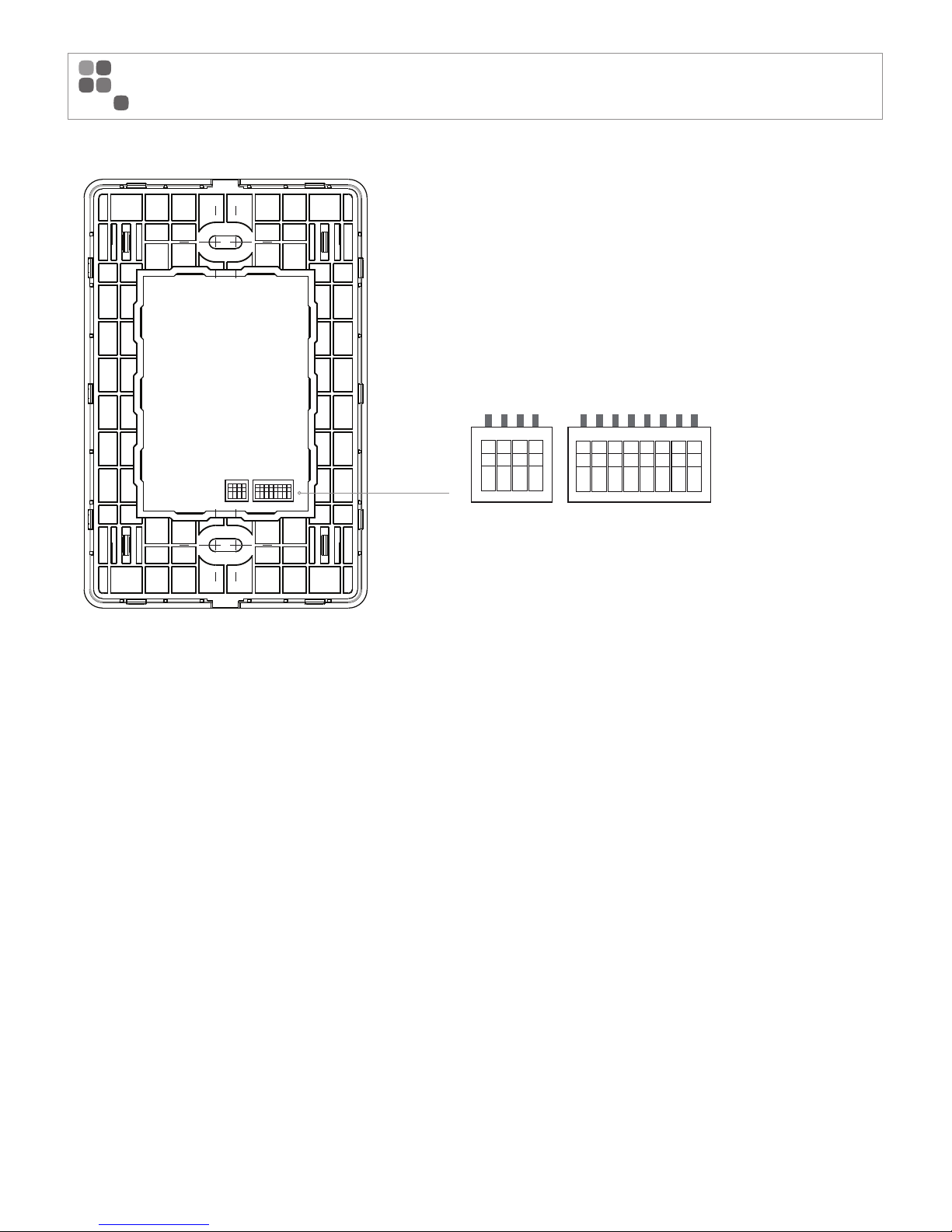
The Revolution series control panels (ICON-CP) have two banks of DIP switches
on the rear of the control panel. The fi rst bank of switches labeled SW1 allows
the user to address the panel for RS485 communications. The second bank of
switches allows the user to set up the LED functions for the remote panel.
SW1:
RS485 addresses 1-240 are allowed. With any other address the unit will blink
its error LED’s.
SW2
A: ON = LED Brightness varies based on ambient light, OFF = Fixed Brightness
B: ON = Low Brightness (if switch A is on fi xed brightnes mode), OFF = Normal
Brightness
C: Unused on Revolution series
D: Unused on Revolution series
The ICON-CP control panels do not hold any project data so if a panel was to
fail or be broken it could simply be swapped out with a unit set to the same
address. All control panels are constantly polling the RS485 network for status.
This will allow the user to update settings via 3rd party, other control panels or
the software GUI and have all panels constantly up to date.
Each RS485 port on the Revolution series allows you to run up to 20 control
panels to a maximum distance of 500 metres. With each unit featuring two
RS485 ports, this allows the AV Revolution to run up to 40 ICON-CP’s on two
separate 500m runs. The 500m limitation of the control panels is due to power
loss over distance and not RS485 limitations meaning if lengths longer than
500m are required you need to inject power locally for greater distances.
ICON-CP Control Panel
PAGE 10
ZONE REVOLUTION QUICKSTART MANUAL
CONTROL PANEL OPTIONS
SW2 Func
SW1 Address
ABC
D
1248163264
128
Page 13
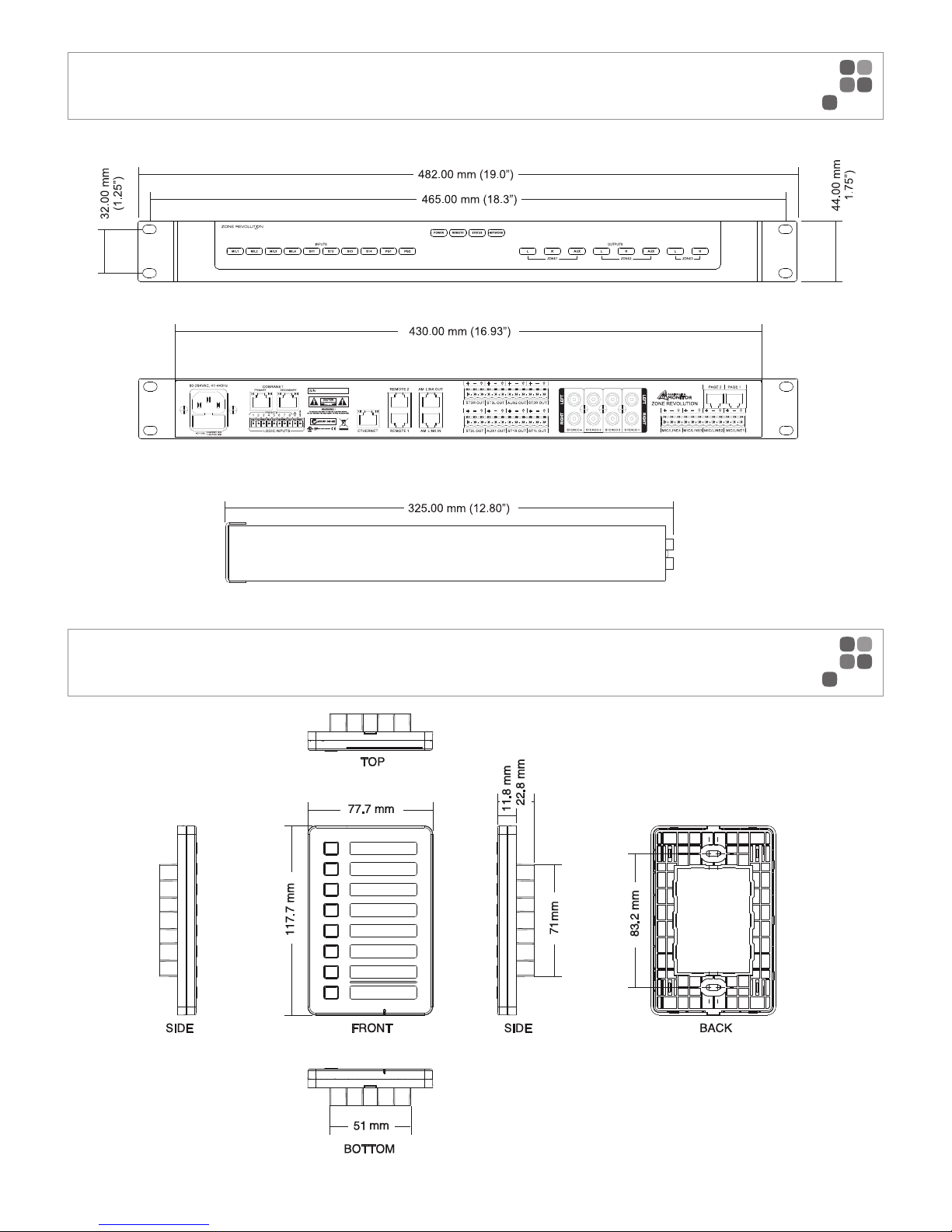
PAGE 11
ZONE REVOLUTION QUICKSTART MANUAL
ZONE REVOLUTION DIMENSIONS
ICON-CP DIMENSIONS
Page 14
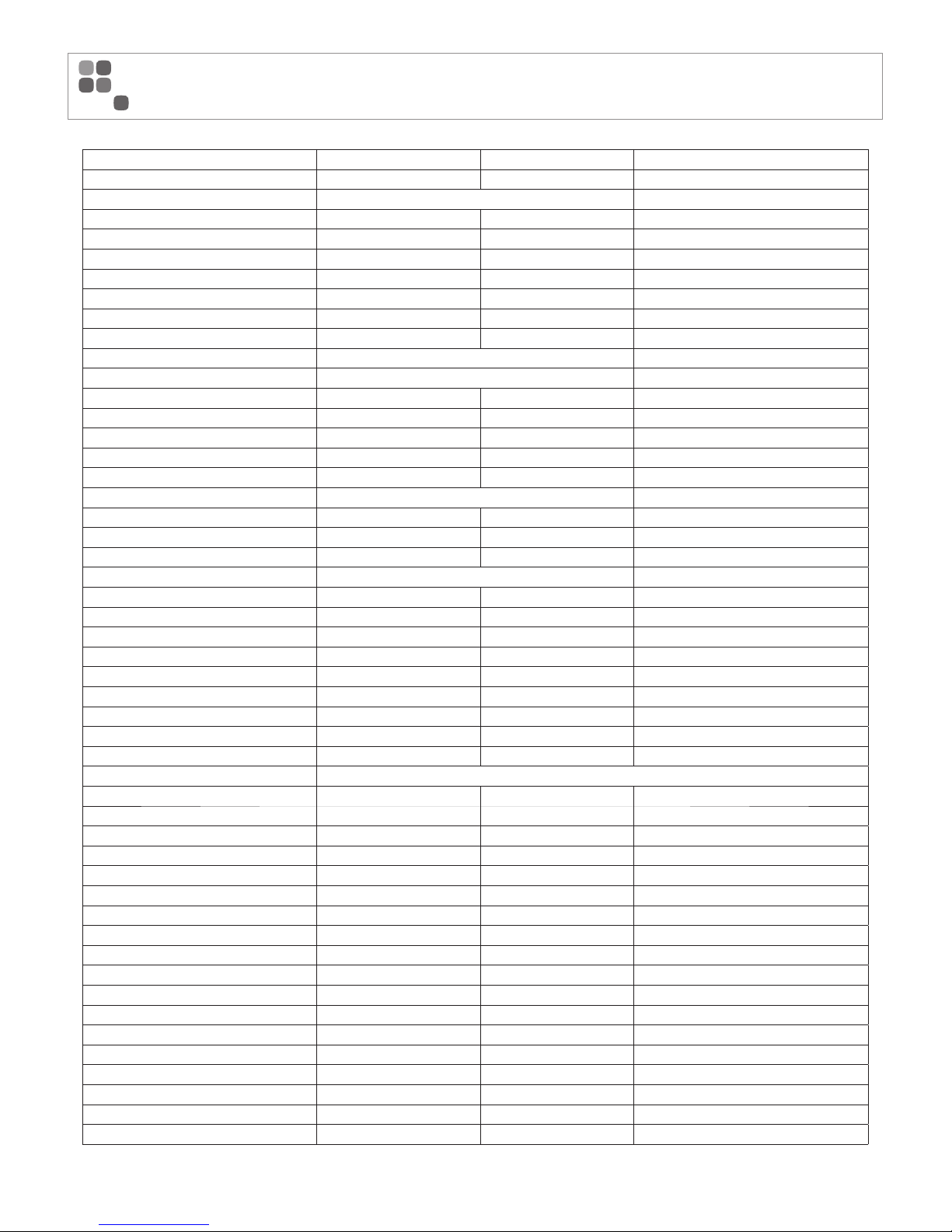
Parameter Specifi cation Unit Conditions
Analog I/O
Balanced Mic Input Euroblock Connectors
Impedance 2 K Ohm
Phantom Power 48 V Selectable per input
Gain / Max Input
Gain Max Input
6 dB 6 dBu
24 dB -12 dBu
42 dB -30 dBu
60 dB -48 dBu
Balanced Line Input Euroblock Connectors
Impedance 5 K Ohm
Gain / Max Input
Gain Max Input
-12 dB 24 dBu
+6 dB 6 dBu
Unbalanced Line Input RCA Connectors
Impedance 15 K Ohm
Maximum Input 6.2 dBu
Balanced Outputs Euroblock Connectors
Impedance 50 Ohm
Maximum Output 24 dBu
System
Frequency Response 20 – 20000 Hz
THD + N 0.003 % From Input to Output (1KHz +4dBu)
Dynamic Range 108 dB
Sample Rate 48 kHz
Latency 2.1 ms Analog to Analog
Processor
2 x Analog Devices Sharc DSP (ADSP-21375) 32/40 bit fl oating point
Processing Power 2 x 1596 MFLOPS
Communications
Ethernet 100 Base T
Icon Control Panel RS485 500 m Max cable length per port without external power
20 Max number of remote panels per run
240 Total using external power
Icon Page Stations 500 m Max cable length per port
Hardware
Net Weight 4.15 kg
Size (w x d x h) 482 x 330 x 44 mm
Chasis Style 1 RU
Voltage 90 – 264 VAC
Power Consumption <30 VA
Compliance ETL ETLc
CE
CTICK
PAGE 12
ZONE REVOLUTION QUICKSTART MANUAL
SPECIFICATIONS
Page 15
PAGE 13
ZONE REVOLUTION QUICKSTART MANUAL
NOTES
Page 16

ENGINEERED BY AUSTRALIAN MONITOR
Address: 1 Clyde Street, Silverwater, Sydney NSW 2128 Australia. Private Bag 149, Silverwater NSW 1811 ABN 78 001 345 482
Website: www.australianmonitor.com.au International enquiries email: [email protected]
DISTRIBUTED IN AUSTRALIA AND NEW ZEALAND BY HILLS SVL www.hillssvl.com.au
NSW P: 02 9647 1411 QLD P: 07 3852 1312 ACT P: 02 6260 4544 WA P: 08 9204 0200 VIC P: 03 9890 7477 SA P: 08 8408 8300 NZ P: 09 415 9426
 Loading...