

Page 1

INSTALLATION AND OPERATION MANUAL
Voice Line VL8
COLUMN LINE ARRAY SPEAKER
Page 2

IMPORTANT SAFETY INFORMATION PRÉCAUTIONS DURANT UTILISATION
1. Read these instructions.
2. Keep these instructions.
3. Heed all warnings.
4. Follow all instructions.
5. Do not use this apparatus near water.
6. Clean only with dry cloth.
7. Do not block any ventilation openings. Install in accordance with the
manufacturer’s instructions.
8. Do not install near any heat sources such as radiators, heat registers,
stoves, or other apparatus (including amplifiers) that produce heat.
9. Only use attachments/accessories specified by the manufacturer.
10. Use only with the cart, stand, tripod, bracket, or table specified by the
manufacturer, or sold with the apparatus. When a cart is used, use caution
when moving the cart/apparatus combination to avoid injury from tip-over.
11. Refer all servicing to qualified service personnel. Servicing is required
when the apparatus has been damaged in any way, such as power-supply
cord or plug is damaged, liquid has been spilled or objects have fallen into
the apparatus, the apparatus has been exposed to rain or moisture, does
not operate normally, or has been dropped.
12. This appliance shall not be exposed to dripping or splashing water and that
no object filled with liquid such as vases shall be placed on the apparatus.
13. WARNING: To reduce the risk of fire or electric shock, do not expose this
apparatus to rain or moisture.
1. Lisez ces instructions.
2. Tenez ces instructions.
3. Notez tous les avertissements.
4. Suivez toutes les avertissements.
5. N’utilisez pas ce produit près de l’eau (la piscine, la plage, le lac, etc.).
6. Nettoyez seulement avec une étoffe sèche.
7. Ne bloquez aucuns troux de ventilation. Installez en accord avec
les instructions du manufacturier.
8. N’installez près aucunes sources de chaleur comme radiateurs, registres
de chaleur, fours ou les autres équipements (y compris amplificateurs)
qui produisent la chaleur.
9. Seulement utilisez attachements/accessoires spécifiés par le
manufacturier.
10. Utilisez seulement avec un chariot, un stand, un trépied, un support
ou une table indiquée par le manufacturier, ou vendue avec l’appareil.
Quand un chariot est utilisé, faites attention en déplaçant la combinaison
d’appareil/chariot pour éviter de se déséquilibrer.
11. Référez au personnel qualifié de service pour toutes réparations. La
réparation est donnée quand le système a été endommagé à n’importe
façon, par exemple un fil ou une fiche endommagé(e) de la source
d’alimentation. Avoir été exposé à pluie ou humidité, n’opère pas
normalement, ou avoir été tombé.
12. L’appareil ne doit pas être exposé aux écoulements ou aux éclaboussures
et aucun objet ne contenant de liquide, tel qu’un vase, ne doit être placé
sur l’objet.
13. AVERTISSEMENT: Pour éviter le risque d’incendie ou de chocs électriques,
ne pas exposer cet appareil à la pluie ou à l’humidité.
Page 3
INTRODUCTION AND CONTENTS
VOICE LINE VL8
The Voice Line VL8 is a unique professional column
line array loudspeaker providing high fidelity sound
reinforcement with a wide cylindrical wave pattern.
A true line array source, it performs remarkably in venues
with poor acoustics and dramatically reduces unwanted
feedback during live performances.
The Voice Line VL8 was designed to perform to strict
acoustic parameters. Critical in the design is the high
frequency waveguide. Typical column line arrays entrust
the high frequency reproduction to the cone drivers.
While this fulfils the SPL requirement, it almost always
fails to meet the necessary frequency extension required to
generate cylindrical waves at high frequencies.
The innovative waveguide utilises 8 identical 1” custom
tweeters coupled to a fibre reinforced waveguide which, in
conjunction with the robust 3” mid-range drivers, produces
impressive frequency bandwidth and true cylindrical waves.
What this means is that for every doubling of distance, the
sound pressure level drops
by just 3dB, not 6dB as with conventional speaker systems.
This ensures uniform coverage in the horizontal span
of 110º.
The Voice Line VL8 enclosure is fabricated from 5mm solid
extruded aluminium with die-cast end caps. The rigidity
provided ensures cabinet resonance is minimised and
there are no spurious noises or unwanted colouration.
The front grille blends with the slender aluminium
enclosure providing an attractive architecturally pleasing
result. Speaker colours include black (VL8B) or white
(VL8W) and several mounting options are available
including fixed, variable angle and pole mounted brackets.
The Voice Line VL8 provides both direct voice-coil and
constant voltage operation via a rear panel selection
switch.
INTRODUCTION 3
FRONT PANEL 4
REAR PANEL 5
ACCESSORIES & SPARE PARTS 6
MOUNTING 7
POLAR RESPONSE & CONNECTION 8
POWER TAPPINGS 9
DIMENSIONS 10
SPECIFICATIONS 11
VOICE LINE VL8 INSTALLATION AND OPERATION MANUAL
Revision 1.0 September 2012
PAGE 3
Page 4
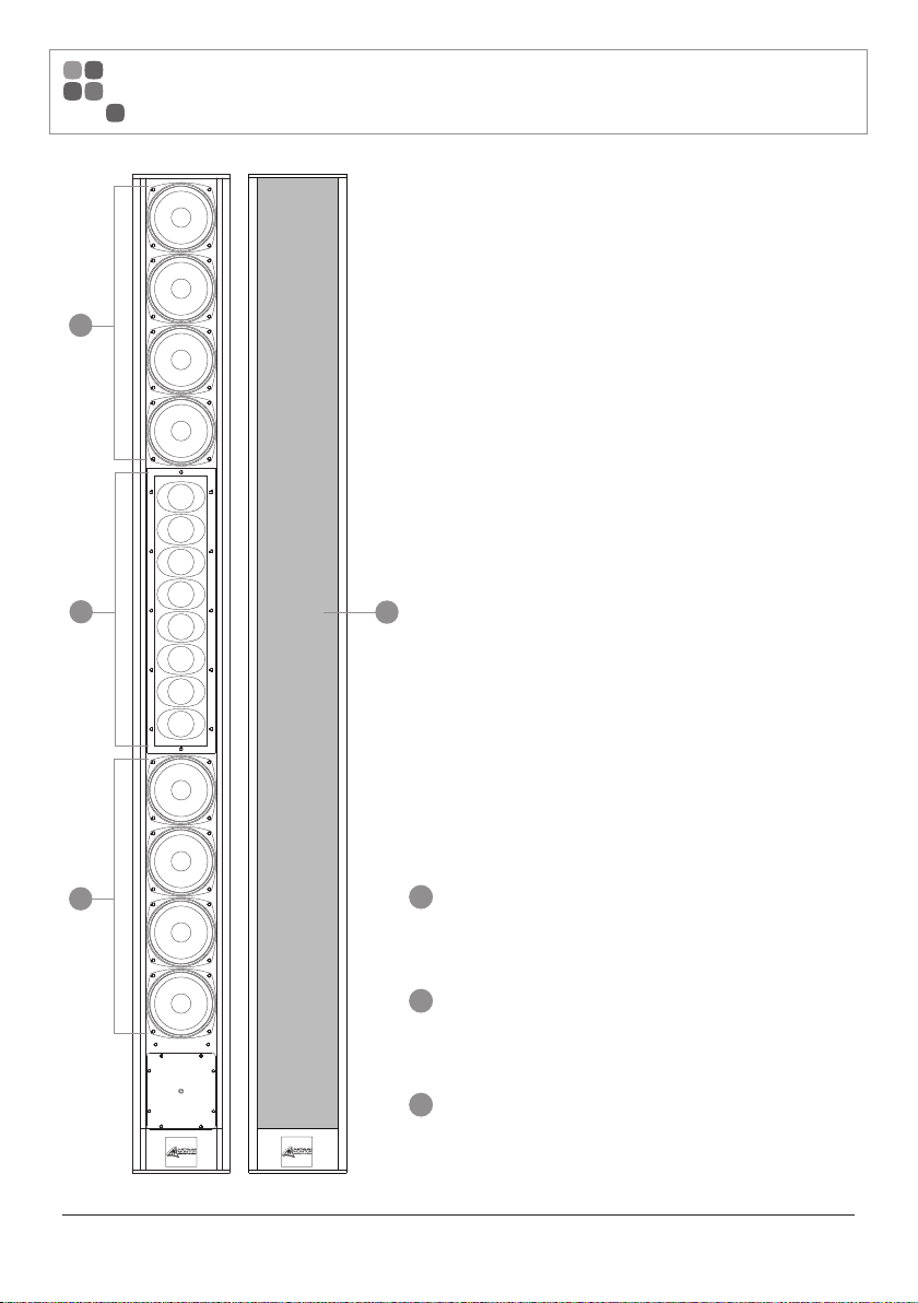
FRONT PANEL
1
2
1
PAGE 4
3
1
Full-range drivers
8 x 3” Polypropylene full range drivers
2
High Frequency Drivers
8 x 1” soft dome tweeters with built-in waveguides
3
Removable front grill
1.5mm thick perforated nylon, covered with
acoustically transparent fabric
VOICE LINE VL8 INSTALLATION AND OPERATION MANUAL
Page 5

REAR PANEL
2
2
1
2
3
4
VOICE LINE VL8 INSTALLATION AND OPERATION MANUAL
1
Speaker Input Connector
4 pole twist lock connector - direct 4 Ohm or
70 / 100 V Input
2
Mounting Points
Several mounting points are provided to attach
the VL8 to the optional mounting bracket.
These thread points are M8 and require at least
15 mm of thread length (provided pre-fitted to
speaker).
3
Power Tap Select Switch
This switch provides selection of the desired
70 / 100 V transformer tap or the 4 Ohm
low impedance transformer bypass option.
4
Tuned Bass Port
PAGE 5
Page 6

ACCESSORIES & SPARE PARTS
Accessories
VL8BUB Bracket U Black – Standard wall mounted U Bracket, fixed
VL8WUB Bracket U White – Standard wall mounted U Bracket, fixed
VL8BAB Bracket Angle Black – Wall bracket with adjustable angle capability
VL8WAB Bracket Angle White – Wall bracket with adjustable angle capability
VL8BPB Bracket Pole – adapter to fit most portable speaker stands
Spare Parts
VL8WOOF Replacement Bass Driver
VL8TWEET Replacement individual Tweeter
VL8ARRAY Replacement Tweeter Array
VL8BG Front Grill Black (with cloth)
VL8WG Front Grill White (with cloth)
VL8TX Transformer
VL8XOVER Crossover Network
ATC6063 Right angle 4 pole twist connector
PAGE 6
VOICE LINE VL8 INSTALLATION AND OPERATION MANUAL
Page 7

MOUNTING
When mounting Voice Line VL8 speakers the following safety issues must be considered;
The mounting of a permanently installed speaker may be dangerous unless undertaken by
a qualified professional with relevant experience.
Walls and mounting surfaces must be capable of supporting the speaker and bracketry in a
safe and secure manner.
All fixings must be safely attached to the speaker cabinet and the mounting surface. All fixings
must be installed in accordance with the manufacturer’s instructions and specifications.
Mounting Brackets
Various mounting bracket options are available for the VL8 column speaker.
The VL8BUB / VL8WUB wall mount U bracket is primarily a fixed design and allows for a discrete
installation. The bracket does however, allow for a limited side to side adjustment.
The VL8BAB / VL8WAB angled wall mounted bracket allows for vertical installation through a wide
range of angular adjustment in both the vertical and horizontal axis.
The VL8BPB pole mount bracket is also available. Primarily designed for temporary installations, the
bracket allows the column speaker to be fixed to a standard 35 mm diameter speaker-stand pole.
VL8BUB / VL8WUB VL8BAB / VL8WAB VL8BPB
60.0
709.0
100.0 100.0 100.0 100.0 100.0 100.0 54.5
54.5
VOICE LINE VL8 INSTALLATION AND OPERATION MANUAL
ø11.0
47.0
2.6
128.0
32.0
60.0
30.0
16.0
112.0
ø7.0
16.0
30.0
150.0
ø35.0
10.0
All measurements in mm
PAGE 7
Page 8

POLAR RESPONSE & CONNECTION
Polar Response (Ratio Vs. Angle)
Horizontal Polar Response Vertical Polar Response
Connection
The VL8 Column Line Array speaker uses an industry standard male twist lock 4 pin speaker connection
to access the 4 Ohm or 100 V / 70 V configurations.
The VL8 pin configuration adheres to the audio standard wiring convention, that is pin 1+ positive
and pin 1- negative as shown below, viewed from the rear of the 4 pin female twist lock connector.
Pins 2+ and 2- are not used.
A right angle female 4 pin twist connector is supplied with the speaker column to allow for neat
mounting with the various wall mount bracket options.
PAGE 8
VOICE LINE VL8 INSTALLATION AND OPERATION MANUAL
Page 9

POWER TAPPINGS
A screw driver accessible selector switch is located at the rear of the loudspeaker for selection of either
4 Ohm operation (Direct) or the required power tap for 70 V and 100 V working.
Preferred Impedance Chart
The table below indicates the the impedance option for the various power taps in both 70 V and 100 V working.
Power Tap
60 W 83 Ω 166 Ω
30 W 166 Ω 333 Ω
15 W 333 Ω 666 Ω
7.5 W 666 Ω NA
VOICE LINE VL8 INSTALLATION AND OPERATION MANUAL
Impedance
70 V 100 V
PAGE 9
Page 10

DIMENSIONS
123.8 mm
1264.0 mm
109.6 mm
1255.0 mm
123.8 mm
1264.0 mm
PAGE 10
FRONT VIEW SIDE VIEW REAR VIEW
VOICE LINE VL8 INSTALLATION AND OPERATION MANUAL
Page 11

SPECIFICATIONS
Description 2 way column line array
Nominal Impedance (Switchable) 4 Ohms
Power Tappings (70 / 100 V) 7.5 W (70 V only), 15 W, 30 W, 60 W
Sensitivity (1 W / 1 M) half space 94 dB
Calculated Maximum SPL (Continuous, Peak) 119 dB, 125 dB
Crossover Frequency 1800 Hz
Frequency Response (±1 dB) 180 Hz - 20 kHz
Frequency Range (-10 dB) 140 Hz - 25 kHz
Dispersion (H x V) 110º x 20º
Continuous Power Handling (IEA RS 426) 300 Watts
Connection 4 pole twist lock connector
Components 8 x 3” poly cone woofer
8 x 1” dome tweeter with waveguide
Net Dimensions (W x D x H) 125 x 110 x 1264 mm
(4.9” x 4.3” x 49.8”)
Shipping Dimensions (W x D x H) 174 x 174 x 1325 mm
(6.9” x 6.9” x 52.1”)
Net Weight 10.3 kg
(22.7 lbs)
Shipping Weight 12.2 kg
(26.8 lbs)
Optional Mounting Brackets VL8BUB / VL8WUB, Wall mount U bracket
VL8BAB / VL8WAB, Wall mount adjustable angle bracket
VL8BPB, Pole mount bracket
VOICE LINE VL8 INSTALLATION AND OPERATION MANUAL
PAGE 11
Page 12

ENGINEERED BY AUSTRALIAN MONITOR
Address: 1 Clyde Street, Silverwater, Sydney NSW 2128 Australia. Private Bag 149, Silverwater NSW 1811 ACN 007 573 417
Website: www.australianmonitor.com.au International enquiries email: international@australianmonitor.com.au
DISTRIBUTED IN AUSTRALIA AND NEW ZEALAND BY HILLS SVL www.hillssvl.com.au
NSW QLD ACT WA VIC SA NZ
P: 02 9647 1411 P: 07 3852 1312 P: 02 6260 4544 P: 08 9204 0200 P: 03 9890 7477 P: 08 8408 8300 P: 09 415 9426
E: nsw@hillssvl.com.au E: qld@hillssvl.com.au E: act@hillssvl.com.au E: wa@hillssvl.com.au E: vic@hillssvl.com.au E: sa@hillssvl.com.au E: sales@hillssvl.co.nz
 Loading...