

Page 1
Page 2
Australian Monitor Pro
The
mixers
console
feature
With
a
and switchable 48V
3 stage
mixers
are designed to be
packed.
mixture of mono channels featuring balanced XLR or TRS inputs
pre
E0 and
as versatile as they are cost effective.
are
Series SM12 and SM16 stereo
compact,
phantom power,
postlader
and
and
auxiliary sends, the SM series
low noise
ultra
stereo channels all
INTRODUCTION
and
MONO CHANNELS
STEREO CHANNELS
boasting
MASTER SECTION
The
SM Series
filters on all mono channels, high
potentiometers.
graph
meters for the
The Australian Monitor Pro
professional
versatility
and
mixers feature
19 inch rack mount kit and
stereo output
a sonically superior mixing console offering a feature set
usually
peak
Series
found in mixing consoles many times their
LED indication and low cut
quality
60mm faders and sealed
accurate
buss.
SM12 and SMl6
10 segment bar
give
the audio
price.
REAR PANEL
OPERATION
BLOCK DIAGRAM
SPECIFICATIONS
gUR,
AUS,
Copyrigtrt
tTth
Rev A: lfth Oct 2Of
Oct
t0
USA
2U!4
CAUTION
CAUTION:
TO REDUCE THE RISK OF ELECTRIC
DO NOT REMOVE COVER
NO
USER-SERVICEABLE
(OR
PABTS INSIDE.
BACK).
WARNING !
TO REDUCE THE RISK OF FIRE OR ELECTRIC SHOCK.
DO NOT EXPOSE
SMt2 &
gM16
THIS
EOUIPMENT
TO RAIN OR MOISTURE.
0ptRAT|*H f!4ANUAL
SHOCK.
A
A
Caution:
This symbol is intended to alert
of uninsulated
enclosure
constitute a
This symbol is intended to alert
of important operation and
instructions in the literature accompanying
prevent
To
with
an extension
the blades can be
prevent
To
wide slot, fully insert.
"dangerous voltage"
that may
electric shock do
electric shock,
be of
risk
of electric
cord, receptacle
fully inserted
the user to
within the
sufficient magnitude to
shock to
maintenance
match wide blade
persons.
the
user
not use this
or
other
prevent
to
pres€nce
the
product's
presence
to the
(servicing)
the
appliance.
(polarised) plug
outlet unless
blade exposure.
plug
of
lo
PAGE 3
Page 3
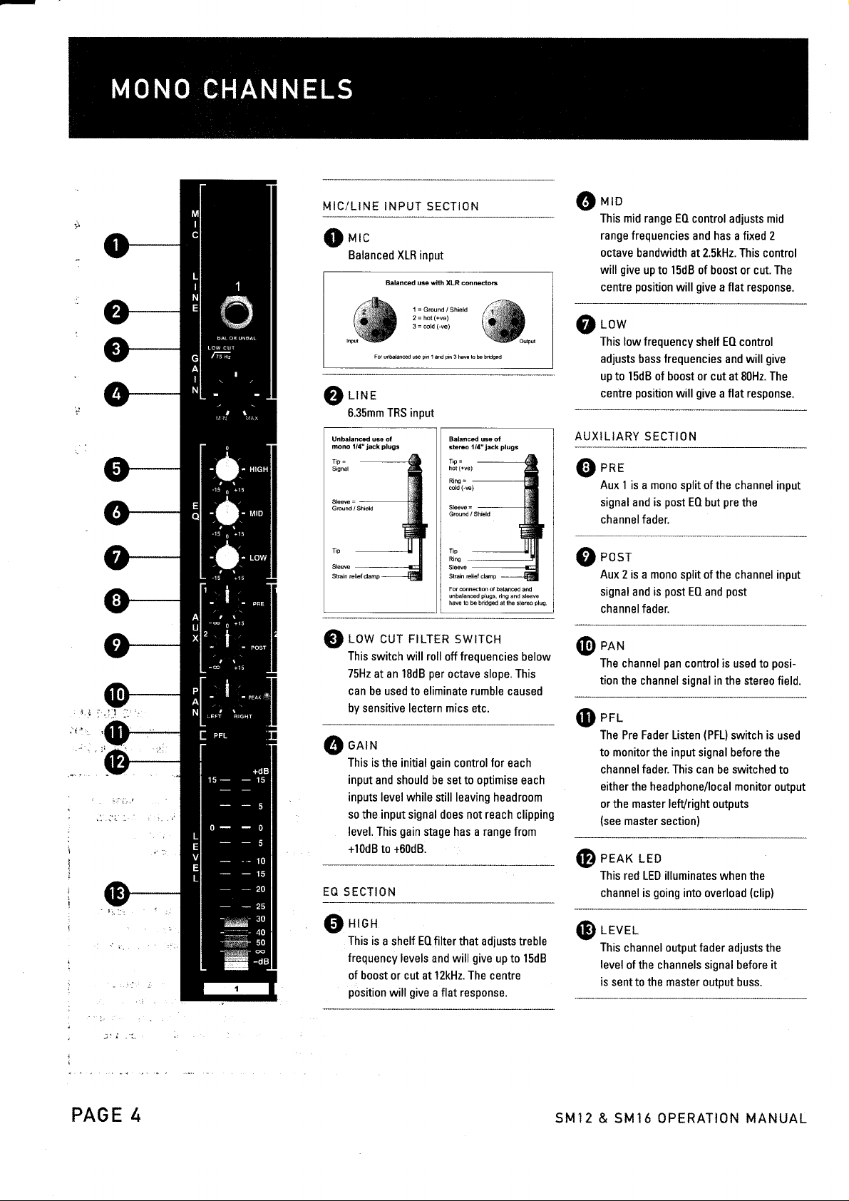
MIC/LINE
r',lrc
{$
Balanced
INPUT
SECTION @
XLR input
uro
This mid range E0
range frequencies
octave
bandwidth at 2.5kHz. This control
give
will
centre
up to l5dB of boost or cut. The
position
control adiusts mid
and has a fixed 2
give
will
a flat response.
i:if.,rl""r,*,.
"@
For
LIN
E
6.35mm TRS input
Unbalan@d use of
mono 1/{"iack
TiP
=
Signal
Grcund/Shield
r-ow
@
This switch will roll
75Hz
at an 18dB
can be used to eliminate rumble
i.
i
\
!
t
by sensitive lectern
onrru
@
This is
input
and should be set to optimise
inputs level while
so the input signal does not reach clipping
level. This
+10d8 to +60d8.
EG SECTION
uroH
@
This is
frequency
of boost or cut at l2kHz. The centre
position
pi.
unhland u*
plugs
1 ad
cur FTLTER swrrcH
per
the initial
a shelf E0 filter that adjusts treble
gain
still leaving headroom
gain
stage has a range from
levels and will
give
will
a flat response.
@^,_
pin
3 hv€ L b bndg€d
Balanced use ot
sterco l//1"
Ring
Gound /Shisld
Tip
Ring
For onndton of balaned
unbalaned
have b h bridgsd at ihe sters
off
octave slope. This
mics etc.
control for
plugs
lack
-
=
plugs,
dng and sleve
frequencies
give
up to 15dB
caused
each
ad
plug
below
each
r-ow
$
This low frequency
adjusts
bass
up to 1 5dB of boost or cut
position
centre
AUXILIARY
enr
@
Aux
signal and is
channel
rosr
@
Aux 2 is a mono
signal and is
channel fader.
e*r.r
@
The
tion
err
@
The Pre Fader Listen
SECTION
1 is a mono split of the channel
fader.
channel
the channel signal in the stereo
shelf E0 control
frequencies
give
will
post
E0 but
split of the channel input
post
E0
and
pan
control is used to
(PFL)
to monitor the input signal
channel fader. This can be switched
either the headphone/local monitor
or the master lelVright outputs
(see
master section)
eenrc
@
@
r-ro
This
red LED illuminates when the
channel is
going
into overload
r-evrr-
This
channel output fader adjusts the
level
of the channels signal before it
is sent to the master output buss.
and will
at 80H2. The
flat response.
a
pre
the
post
switch
before the
(clip)
give
posi-
is
output
inpul
field.
used
to
PAGE 4
SM12
& SM16 OPERATION MANUAL
Page 4

-
LINE INPUT SECTION AUXIL!,E.RY STfTiCN
r-rn
lrxr
@
These 6.35mm TRS
balanced or unbalanced line
either
level signals.
left input only.
Unbalaned u3e of
mono t/4-jack
TiP
Sigml
plugs
=
lacks
For mono
Balanced u3e of
sbrco 1/4"lack
Tip
Grcund /Shield
Tip
Ring
For 6nnslion
unbalan@d
have to & bridged at rhe stereo
operation
=
EO SECTION
Hron
@
This is
a stereo shelf E0 filter
frequency levels
treble
15dB of boost or cut at 12kHz.
position
r,,rro
@
This
mid range
2 octave bandwidth at 2.5kHz.
control will
cut. The centre
response.
low
@
This low frequency stereo shelf
control adiusts bass frequencies and
give
The centre
resp0nse.
give
will
mid range E0 control adjusts
stereo
frequencies
give
up to 15dB of boost or cut at 80H2.
position
and
a flat response.
and
up to 1SdB of boost or
position
will
will accept
plu96
of balao@d and
plugs,
ing and sleeve
that
will
The
has a fixed
This
give
will
give
flat
a
use
adjusts
give
a
E0
plug
up
centre
flat
will
rcr
@
Aux 1 is a mono split of
input signal
channel fader.
Fosr
ts,
Aux 2 is a
input signal and
channel fader.
r*x
@
The channel
position
field.
as this
of either
to the master
control
Right signal
master mix. lf the
connected
to
will work as
rrax r-r*
$
This red LED
channel
ppi-
9D
The Pre
to monitor
channel fader. This can be switched to
either
output or
(see
L E\"'f L
f*il
This Channel output
level ofthe channels
is
sent
and is
mono
pan
channel signal in the stereo
the
This
differs
pan
control will determine
the Left or Right buss that
mix. For example if the
is turned fully clockwise, only
path
(a
mono signal)
per
illuminates when the
going
is
Fader Listen
the input signal before the
the headphone/local
the master
master sectionl
to the Master output
the channel
E0 but
E0 and
pre
post
the
the level
is
pan
post
of the channel
split
post
is
control is used to
from the mono channels
will be sent to the
Left input
mono
the
into overload
(PFLI
lefVright outputs
fader adlusts the
signal before it
is
only
pan
the
channels.
(clip)
switch
monitor
buss.
control
is used
sent
the
5Mt2 & SMi6 CFTftAT'ilru
M&iliUAL
P&*e
*
Page 5

i*te.:.-
ffi
These
output that can
amp and speakers
box monitoring
the master
Tp
Sleeve
StEin reliefcramp
]
i-:,i*pHe
#
This
a monitor output for headphones.
This
outputs signal will follow whatever
assigned
a*x *eru*r!
ffi
These
auxiliary returns.
permanently
u t a*r
ffi
This
control adjusts the
Local
ta*>;
jacks
TRS 6.35mm
be sent to a local monitor
provide
for control room
of either the PFL
output buss.
Balaned
stereo l/4"iack
Rins
=
Tip
Ring
Sleeve
For onnedion orbaranced
I
unbalan@d
I
have to be bndoed
I
n r:
to the Local Monitor
1r:
controls adjust the level
Both Aux Return
assigned to
"'t*i4r.
i L}r; f,.L
Monitor outputs
the Master Mix.
M
* G tT* *
output level of the
and the Headphone
a stereo
buss or
use of
plugs
pluqs,
i,nq and sleeve
ar the sreeo
output.
of the stereo
1 & 2 are
or bio
and
ptuq
t rv € t
f'J;* PC$JEF? LEX
w
@
A
3i'}
?
I
I
i
@
is
$
output. This level is independent
the Master Mix.
This LED indicates that
the mixer is
+e*v
This LED indicates that 48
power
is active.
L.R CUTSUT
The Master
these l0
i.4A$TEftIFFL
This
switch determines whether
mix
signal or the PFL signal will be
the Local Monitor/Headphone
iITTER
0utput level is displayed
segment Bar
T0 L0CAi_
rnreinec ro
This
switch determines whether
other stereo source
Tape ln RCA
Master Mix.
uesrrn
This fader
both the Left and Right busses
XLF and TRS outputs
connectors is sent
ourPur
controls the master output level
volt
peak
Graph
output.
MAsTER
connected
to the master
ofthe mixing console.
of
"on"
phantom
on
meters.
t4*t1t7c*
the Master
sent to
a tape
to the
to the
or
o1
PASE 6
al€*^t*
These 2 additional
used for the return
units such as reverb
permanently
are
Mix. These
line
level inputs and can
the left input is
r{T'*rrr5
itl:,'E
assigned to the Master
can also be used
used.
1i2
stereo inputs can be
of stereo effects
or delay units and
as extra
mono if
be
only
*
AUX SEND
*FI
These
unbalanced 6.35mm
be used to send the output
channels Aux sends to
such
reverb
as
ffi;;*
TArE rfii
These
stereo RCA connectors
connection of a tape
player
etc to the mixer and are routed
the Master
&
*BFd L,,F RICSED OUT
w
These
stereo RCA connectors
a tape deck or digital recorder
connected to mixing
5Mi?
recording
& Sld'l$ *pftATlSl* t"{Al.lUA'-
the output of the Master
.I/?
or delay units.
Mix.
jacks
of each
effects devices
allow
deck, CD/DVD
allow for
to be
console for
can
to
Mix.
Page 6

Balanced
stereo
Tip
hot
Ring
cold
Sleeve
Ground / Shield
=
(+vs;
(-ve)
use of
1/4"
=
jack
plugs
:t.l=r-ar*
ffi
An insert
Mono Channel
mixing
a split
which is
filter with
inserts
being send and ring
1
I
i---*
1-i t.,.'4
point
provided
is
on the
consoles. These
of the channels
post
the return
are 6.35mm
gain
input
TRS sockets with
being return.
'{=z
*?e
for
each
SMl2 and SM16
points
insert
input signal
and Low
path pre
EO. These
?{.4':
cut
are
1rp
+i
Tip
Ring
Sleeve
Strain relief
For
unbalanced
have to
l'ip
=
Send, Ring
clamp
connection of balanced
plugs,
=
ring and
fts1x1n
be bridged at the stereo
and
sleeve
plug
&&
&
9 W 3 ?-
**w;.*
This
switch turns mains
the mixer
ot **w??.
This is
the connection
power
AC
Please use
power
connect the
mixer
mains
:*
5
7a.
supply.
1
+ 3
"on"
power
for the supplied
supplied mains
supply
belore connecting to
supply.
p g,'6
only.
power
it."T
Always
supply to
?4
*
t
7,;
to
the
the
*"?'i
**,**z';*
&
This
switch turns 48 volt
"on"
to all mono
power
is required
Condenser style microphones
*:;.-*.2,:
&
Both
jacks
mix output
output fader.
be
2.j
&.r-
*l:r
balanced XLR
are included
at the level set
Both sets
used simultaneously.
phantom
channels. Phantom
for Electret
and 6.35mm TRS
and
or
provide
Stereo
by the Master
of outputs can
power
?&**
7
Page 7

-
:
Fi tEEffi.ffi] @ PTPPTF l'
tr,+t=LEL=lElgF-t
Et
\--./
@]qEElEll
l_
Before
connecting any input
console mixer,
.
gain
All
controls
.
All Auxiliary
.
E0 is
set flat
.
Ensure the
.
No PFlls
are active
EE
I't
GbJ+jt-h.EE.uE.LlE.O,|@;
oir CI'r
please
make
faders
and
sends are set to minimum
(i.e.
in centre
power
supply is
Or o"r eJ'o*
to minimum
set
your
SM12 or SM16
initial settings
sources to
sure the following
are
positionl
correctly connected
i6
stereo
are correct.
O'
6
|O,I
@,
|(b:ro
S.t tnr Master
S
furn up the input
$
(half
Generate input signal
O
(i.e.
E
way)
voice for a microphone,
rAPE
OUTPUT
L&R
Output to unity
gain
your
for
-l_
play
@€l
(set
gain
selected
background
INPUT
L&R
"0")
to
channel to 12 0'clock
source etc)
Connect mic
phantom power
are correctly connected to
line
or
source to desired channel
is
switched on if required)
PAGE 8
your
audio system.
(make
inputs
and ensure Master
sure
Outputs
!l Enrrrc
Gl
$
S|
€3
@
cr
the selected channels Peak LED is not
Ruirr
the selected channels fader till the
ff'r
0utput meter
UR
with
any transient signals not exceeding the +6dB indicator.
nO;ust
input
,O input signals
will add
to
Repeatfor remaining
ltl0TE: A lull
correct
procedure
The
correctly set up external
prior
mixer
should be continuously metering at
gain
stage to
ensure correct
required
as
the
signals
discussion of setting up a
gain
structure is
above
to initiating
5MI2
remembering that boosting frequencies
gain.
channels
beyond
assumes that the installer has
equipment connected to this
the setup
& SMJ6 OPTRATION MANUAL
illuminating
level
desired
gain
settings
complex system with
the
scope olthis manual.
procedure.
is achieved
up to 0dB
Page 8

ald
EXNV
'XNV
|tld
Fr,Fr'
U
I
oo
zz
UUZ
@6
xxH
99
JJ
ll
lpl
lc; la
IU IU
lpl=
b6
t'urt
UAY
r>f
F,,
a
X
UL
F
r'
<_
u
z
o
I
=
F,,
a
uj
z
o
-
o-
o
cc
J
tr
F
o
oo
FO
occ
UJ
tr6
cc
ul
*2
FO
o
c
JL J+
tCi! Efi
55 5;
F"
-"
r<F-
cr-
SMI2
& SM16
, F=T-FB
$,-*A
@
J
u
z
2
-J*ta=-
*6 t t ll
I
o
t
+1
o-
z
o
z
o
OPERATION
@J
qE
J
o
E
=
-
-
Ll
6*
MANUAL
T--]-'
F
cc
U
o
z
F
l
&<
Z +t +l
-UU
o
U
CC
U
F
O)ff
o
J
o
=
q
z
CC
l
F
U
cc
x
f
fr-'
o
U
(r
U
F
J
a
PAGE
9
Page 9

INPUT5
MONO
Mic lnput Electronically
Bandwidth
Distortion
Mic E.l.N.
GAIN
(THD
& N)
(22H2-22kHzl
range
balanced, discrete input
10Hz to 60kHz t 3dB
0.01% at
+
dBu, lkHz, Bandwidth
-129.5d8u,
-1
l7.3dBqp,
-132.0dBu,
-1
22.0dBqp, input
configuration
80kHz
l50O
source
I 50C) source
input
shorted
shorted
+10d8 to +60d8
Line lnput
Bandwidth
Distortion
Line Level Range
Equalisation
Hi Shelving
(THD
& N)
Mid Range
Lo
Shelving
STEREO INPUTS
Line lnput
Bandwidth
Shelving
Shelving
Room
(THD
& N)
SECTION
0ut
Ratio
Distortion
Equalisation
Hi
Mid Range
Lo
MASTER MIX
Max. 0utput
Aux. Send Max. 0ut
Control
Signal-to-Noise
Electronically
1()Hz
at +4dBu,
0.01%
0.01% at +4dBu, lkHz, Bandwidth
112d8, all channels
lkHz, Bandwidth
1()Hz to
+22dBu Unbalanced
+22dBu
to 60kHz r3dB
+l0dBu
to
l2kHz tl5dB
2.5kHz tl5dB
80Hz rl 5dB
Unbalanced
55kHz
l2kHz tl5dB
2.5kHz
80Hz
+22dBu
Unbalanced
at Unity Gain
balanced
Balanced
80kHz
-40dBu
r3dB
80kHz
tl 5dB
tl
5dB
POWER SUPPLY
USA/Canada
Europe/Australia
PHYSI
CAL
sM12
(mains
-1l5VAC,
-230VAC,
Dimensions(HxWxD)
Net Weight
Gross Weight
sM16
Dimensions(HxWxD)
Net Weight
Gross Weight
PAGE 1O
vottages)
power
60H2,
power
50H2,
supply unit MXUL2
supply unit MXUK2
70mmx293mmx3tl4mm
(PSU
3.6k9
70mmx399mmx344mm
SkS
(PSU
not included)
not included)
(included)
(included)
5.8k9
8.0k9
SM12 & SMI6 OPERATION MANUAL
 Loading...