

Page 1
MY MUSIC
PROGRAM SOURCE SERIES
INSTALLATION AND OPERATION MANUAL
Page 2

IMPORTANT SAFETY INFORMATION
1. Save the carton and packing material even if the equipment has
arrived in good condition. Should you ever need to ship the unit, use
only the original factory packing.
2. Read all documentation before operating your equipment. Retain
all documentation for future reference.
3. Follow all instructions printed on unit chassis for proper operation.
4. Do not spill water or other liquids into or on the unit, or operate
the unit while standing in liquid.
5. Make sure power outlets conform to the power requirements listed
on the back of the unit.
6. Do not use the unit if the electrical power cord is frayed or broken.
The power supply cords should be routed so that they are not likely
to be walked on or pinched by items placed upon or against them,
paying particular attention to cords and plugs, convenience
receptacles, and the point where they exit from the appliance.
7. Always operate the unit with the AC ground wire connected to the
electrical system ground. Precautions should be taken so that the
means of grounding of a piece of equipment is not defeated.
8. Mains voltage must be correct and the same as that printed on the
rear of the unit. Damage caused by connection to improper AC voltage
is not covered by any warranty.
13. Do not block fan intake or exhaust ports. Do not operate equipment
on a surface or in an environment which may impede the normal fl ow
of air around the unit, such as a bed, rug, weathersheet, carpet,
or completely enclosed rack. If the unit is used in an extremely dusty
or smoky environment, the unit should be periodically “blown free”
of foreign matter.
14. Do not remove the cover. Removing the cover will expose you
to potentially dangerous voltages. There are no user serviceable
parts inside.
15. Do not drive the inputs with a signal level greater than that required
to drive equipment to full output.
16. Do not connect the inputs / outputs of amplifi ers or consoles to any
other voltage source, such as a battery, mains source, or power supply,
regardless of whether the amplifi er or console is turned on or off.
17. Do not run the output of any amplifi er channel back into another
channel’s input. Do not parallel- or series-connect an amplifi er output
with any other amplifi er output. Australian Monitor Inc is not
responsible for damage to loudspeakers for any reason.
18. Do not ground any “hot” terminal. Never connect a “hot” output
to ground or to another “hot” output!”
19. Non-use periods. The power cord of equipment should be unplugged
from the outlet when left unused for a long period of time.
9. Have gain controls on amplifi ers turned down during power-up
to prevent speaker damage if there are high signal levels at the inputs.
10 Power down and disconnect units from mains voltage before making
connections.
11. Never hold a power switch in the “ON” position if it won’t stay
there itself!
12. Do not use the unit near stoves, heat registers, radiators, or other heat
producing devices.
20. Service Information Equipment should be serviced by qualifi ed service
personnel when:
A. The power supply cord or the plug has been damaged.
B. Objects have fallen, or liquid has been spilled into the equipment
C. The equipment has been exposed to rain
D. The equipment does not appear to operate normally, or exhibits a
marked change in performance
E. The equipment has been dropped, or the enclosure damaged.
THIS SAFETY INFORMATION IS OF A GENERAL NATURE AND MAY BE SUPERSEDED BY INSTRUCTIONS CONTAINED WITHIN THIS MANUAL
Page 3
INTRODUCTION AND CONTENTS
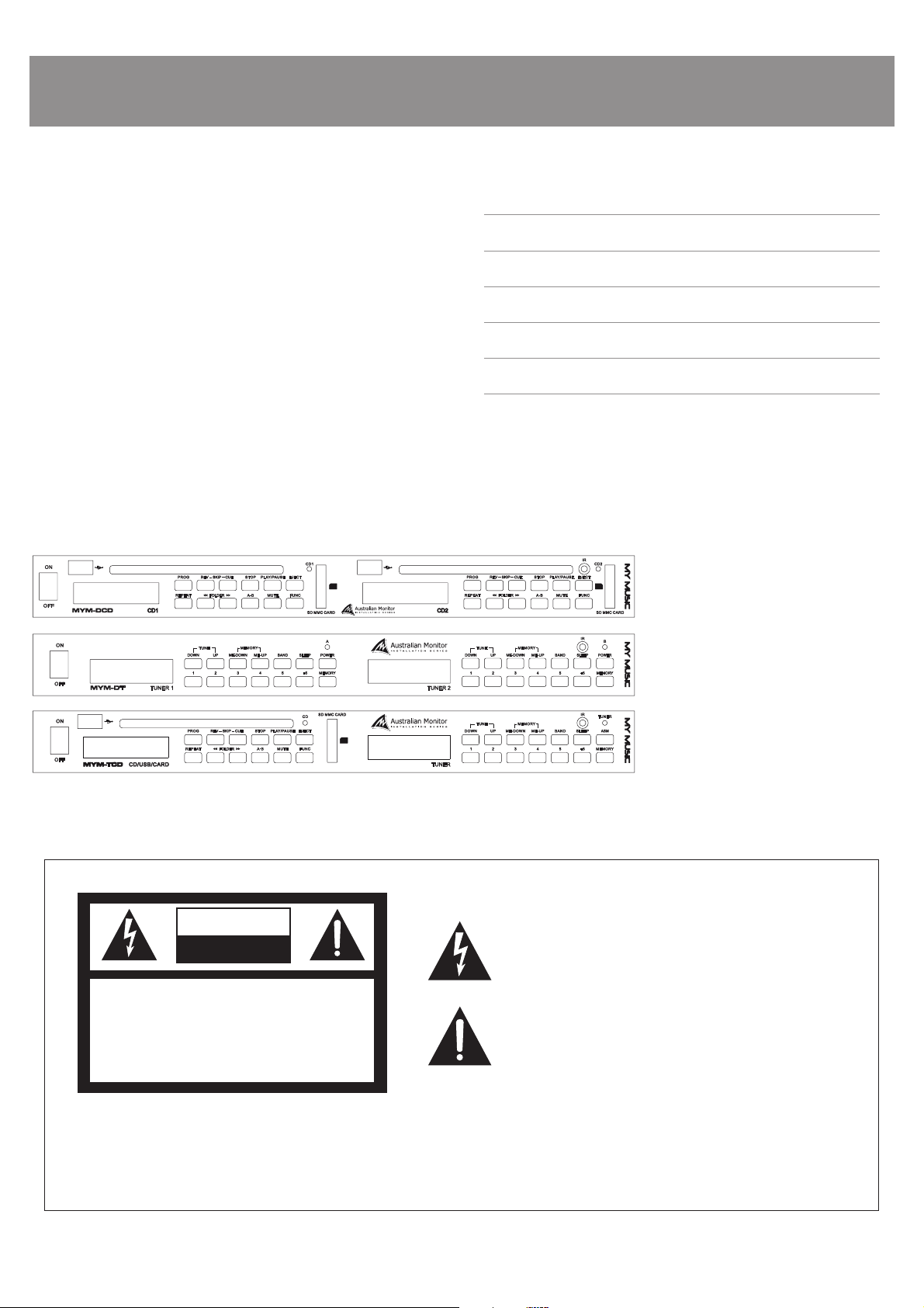
The Australian Monitor Installation Series
one rack unit, dual program source players that features either an AM/FM tuner &
single disc CD/USB player (MYM-TCD), dual CD/USB players (MYM-DCD) or, dual
AM/FM tuner modules (MYM-DT). The tuner module has one FM band & one AM
band, with 10 user selectable preset stations, there is also a programmable sleep
function for the tuner. The CD/USB player is fully programmable up to 20 tracks &
includes Random track selection for CD’s & Repeat Single Track or Repeat All Track
functions for both CD & MP3’s. There is also an optional IR control available for the
CD/USB player. The
tenna (on tuner models). The
both the Tuner & CD player as well as a stereo priority output for the MYM-TCD.
My Music
The
featured dual background music source at a contractor friendly price.
Your
My Music
My Music
series provides a high quality, rack space friendly & extremely well
will be one of these models:
is supplied with an IEC power lead & AM/FM an-
My Music
My Music
also boasts individual stereo outputs from
program source series are
MYM-DCD : Dual CD/USB players
MYM-DT : Dual AM/FM tuners
MYM-TCD : 1 AM/FM Tuner and 1 CD/USB player
INTRODUCTION 1
FRONT PANEL 2
BACK PANEL 4
RS232 CONTROL 5
SPECIFICATIONS 7
NOTES 8
The following shows an MYM-TCD which has both module types for explanatory purposes.
CAUTION
RISK OF ELECTRIC SHOCK
DO NOT OPEN
CAUTION: TO REDUCE THE RISK OF ELECTRIC SHOCK,
DO NOT REMOVE COVER (OR BACK),
NO USER SERVICEABLE PARTS INSIDE,
REFER SERVICING TO QUALIFIED SERVICE PERSONNEL.
Caution:
WARNING!
TO REDUCE THE RISK OF FIRE OR ELECTRIC SHOCK
DO NOT EXPOSE THIS EQUIPMENT TO RAIN OR MOISTURE.
AUS, EUR, USA
Copyright 9th Feb 2006
Rev D: 3rd June 2008
Rev E: 12 Dec 2009
Rev F: 22 Feb 2010
This symbol is intended to alert the user to the presence of uninsulated
“dangerous voltage” within the products enclosure that may be of suffi cient
magnitude to constitute a risk of electric shock to persons.
This symbol is intended to alert the user to the presence of important
operational and maintenance (servicing) instructions in the literature
accompanying the appliance.
To prevent electric shock do not use this (polarised) plug with an extension
cord, receptacle or other outlet unless the blades can be fully inserted to
prevent blade exposure. To prevent electric shock, match wide blade of
plug to wide slot, fully insert.
PAGE 1MY MUSIC PROGRAM SOURCE SERIES INSTALLATION & OPERATION MANUAL
Page 4
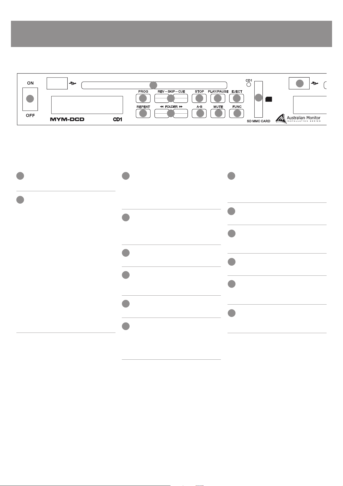
FRONT PANEL – CD/USB PLAYER
1
CD/USB/SD PLAYER
1
POWER
Turns the
My Music
PROG
2
Works with conventional CD’s only, does not apply to
MP3 recorded disks.
Allows you to program up to 20 tracks to play in the
order you program. The program order is not saved
and will be cleared when you press STOP. Use the UP/
DOWN buttons to change track and press PROG to
move to the next program slot. Press PLAY/PAUSE to
start the program order. REPEAT ALL will repeat the
order that has been programmed. While in program
mode, “Pxx” on the LCD display indicates the program
order position. While in program play mode, “Pxx”
on the LCD display indicates the actual track number.
An ordered program cannot be paused. Advance the
program order using UP/DOWN. Once an order position
(“Pxx” in program mode) has been entered it cannot be
changed. Pressing PROG while the track indicator reads
“–“ cycles you through the program order. Selecting UP/
DOWN changes the track number but pressing PROG
again will put that track in the next program position.
player on or off.
13
2 3
7 9
SKIP REV/CUE
3
Pressing these buttons momentarily changes the track.
Pressing and holding these buttons while a track is
playing changes the position within a track. Note that
audio is not audible while changing track position.
4
STOP
Stops the CD/MP3 playing and returns to the start of
the disk. This button also clears the programmed track
order.
5
PLAY/PAUSE
Plays and pauses the track.
6
EJECT
Ejects the disk. Pressing this button while a disk is
ejecting returns the disk to the player.
7
REPEAT
Will cycle though the repeat functions of the unit.
FOLDER FWD REV:
8
For use when playing MP3 (data) CDs, or USB memory
sticks. Jumps to either the next availalble folder, or
previous folder. Moves sequentially through folder tree
structure.
8
4 5 6
10
14
12
11
A-B:
9
Pressing the A button will set a start point and B will
set an end point. Once this has been done, a loop
will cycle between these two points.
MUTE
10
Mute’s the Audio
FUNC:
11
Cycles the unit between CD Player, Mp3 Player and
SD Card player
SD/MMC
12
Card Slot
CD PLAYER
13
This slot is for loading either audio CDs or data
CD-ROMs with MP3 fi les pre-loaded.
USB STICK INPUT
14
This socket is for connecting a USB memory stick with
MP3 audio fi les pre-loaded.
PAGE 2 MY MUSIC PROGRAM SOURCE SERIES INSTALLATION & OPERATION MANUAL
Page 5

SPECIFICATIONSFRONT PANEL – AM/FM TUNER
21
AM/FM TUNER
TUNE (UP/DOWN)
1
Changes the tuner frequency.
MEMORY (UP/DOWN)
2
Changes the preset number.
BAND
3
Changes between AM and FM bands.
4
SLEEP
This button allows you to set a countdown timer to switch the tuner module
off. It is set in increments of 10mins form 90mins to 10mins. Pressing this
button while in sleep countdown mode turns off the sleep function.
3
4
6
5
1-5; +5
5
These buttons allow the immediate selection of a preset.
Use +5 to select 6-10.
MEMORY
6
This button allows the memory setting to be programmed.
To program a memory setting:
1. Tune to the required frequency
2. Press MEMORY (MEMO fl ashes on LCD display),
3. Press a number from 1-5 (or +5 and a number for 6-10)
4. Press MEMORY again.
This process must be completed within 4 secs or you will need to
start again.
PAGE 3MY MUSIC PROGRAM SOURCE SERIES INSTALLATION & OPERATION MANUAL
Page 6

SPECIFICATIONSBACK PANEL
Right side – Back Panel
Left side – Back Panel
1
2
5
3
4
DIRECT STEREO OUTPUTS
1
These outputs provide direct signal from each module.
2
PRIORITY
The
My Music
to the separate Direct Stereo outputs for the modules. The Priority Output
will output the signal from the secondary module until signal appears on the
primary module.
MYM-TCD: CD has priority over TUNER
Signal from the secondary module will return automatically, once the primary
module falls silent.
This feature allows the user to utilize only one input on their mixer/amplifi er
for both modules.
ANTENNA
3
These terminals provide connections for the antenna of each band.
There will be two strips of terminals on the MYM-DT, one for each module.
There is no antenna connection for the MYM-DCD.
MYM-TCD features a STEREO PRIORITY OUTPUT, in addition
NOTE: The above drawing shows the back panel of the 115V
version. Layout is similar for the 230V version.
Correct mains voltage should be noted on the actual unit.
4
IEC MAINS INPUT SOCKET
This is a standard IEC 3 pin socket. It accepts a standard IEC mains cable,
provided. The fuse drawer contains the mains fuse and a spare. The mains
fuse is a time lag (slow blow) HRC 20mm x 5mm ceramic type fuse.
The ratings are:
230V/240V model 0.63mA
115V model 1.25A
Mains connected apparatus covered by this standard is intended for installation
in compliance with the National Electric Code ANSI/NFPA 70.
Always replace the fuse with one of the same
value and type.
NOTE: Always disconnect power to the amplifi er before
replacing fuses.
5
RS232:
This is a DB9 socket for RS232 control. The pin out is:
Pin 2 = TX
Pin 3 = RX
Pin 5 = GND
PAGE 4 MY MUSIC PROGRAM SOURCE SERIES INSTALLATION & OPERATION MANUAL
Page 7

RS232 CONTROL
The MYM series control protocol allows replication of all front panel
controls via RS232.
Baud: 9600
Bits: 8
Parity: No
Stop Bits: 1
Flow Control: No
FORMAT:
ASCII ASCII ASCII HEX HEX
E <Module> <Command> 0d 0a
MODULES:
CD1 ASCII: A
CD2 ASCII: B
TUNER1 ASCII: C
TUNER2 ASCII: D
COMMANDS:
CD Functions Tuner Functions
Folder Skip – A 1 A
Folder Skip + B 2 B
Down C 3 C
Up D 4 D
Stop E 5 E
Play/Pause F 6 F
Eject G 7 G
Prog H 8 H
ESP I 9 I
ID3 J 10/0 J
Mute K +10 K
Play Mode L Direct L
Func M Down M
A-B N UP N
0 0 Me-UP 0
1 1 Me-DOWN 1
2 2 Memory 2
3 3 ASM 3
4 4 MO/ST 4
5 5 Sleep 5
6 6 Band 6
7 7 Auto Down 7
8 8 Auto Up 8
9 9
PAGE 5MY MUSIC PROGRAM SOURCE SERIES INSTALLATION & OPERATION MANUAL
Page 8

RS232 CONTROL CONTINED
RETURN STRINGS:
Command OK:
ASCII ASCII ASCII HEX HEX
+ O K 0d 0a
Command Error:
+ E R 0d 0a
EXAMPLE STRINGS:
Play on CD 2
ASCII ASCII ASCII HEX HEX
Send E B F 0d 0a
Rcv + O K 0d 0a
Preset 2 on Tuner 1
ASCII ASCII ASCII HEX HEX
Send E C B 0d 0a
Rcv + O K 0d 0a
Eject on CD 1
ASCII ASCII ASCII HEX HEX
Send E A G 0d 0a
Rcv + O K 0d 0a
Memory Up on Tuner 2
ASCII ASCII ASCII HEX HEX
Send E D 0 0d 0a
Rcv + O K 0d 0a
PAGE 6 MY MUSIC PROGRAM SOURCE SERIES INSTALLATION & OPERATION MANUAL
Page 9

SPECIFICATIONS
SPEC. OF CD/USB PLAYER
1. Output Level @ 1kHz, 0dB 1.2V +/- 0.3V
2. Frequency Response 20Hz-20kHz +/- 2dB
3. Separation 1kHz, 0dB >60 dB
4. T.H.D+ Noise 1kHz, 0dB <0.05%
5. S /N Ratio >80 dB
Size of SD Card Universal SD STD size
Filetype FAT16 /FAT32
SPEC. OF AM / FM TUNER
FM:
1. Tuning Range
2. IF Frequency & Rejection 10.7 MHz >80 dB
3. Image Rejection >25 dB
4. S/N Ratio 1mV/M Input 46db
5. T.H.D 1mV <1.0%
6. Auto Tuning Sens. <50uV
AM:
1. Tuning Range
2. IF Frequency & Rejection 450 kHz >45dB
3. Image Rejection >30dB
4. S/N Ratio 5mV/M Input >35dB
5. Auto Tuning Sens. <2mV
Dimensions 482 (W) x 44 (H) x 250 (D) mm
87.5 MHz -108 MHz
522kHz – 1620kHz
PAGE 7MY MUSIC PROGRAM SOURCE SERIES INSTALLATION & OPERATION MANUAL
Page 10

NOTES
PAGE 8 MY MUSIC PROGRAM SOURCE SERIES INSTALLATION & OPERATION MANUAL
Page 11

NOTES
PAGE 9MY MUSIC PROGRAM SOURCE SERIES INSTALLATION & OPERATION MANUAL
Page 12

AUSTRALIA AND NEW ZEALAND
www.australianmonitor.com.au
SYDNEY
(NSW SALES)
1 Clyde Street
Silverwater
NSW 2128
Private Bag 149
Silverwater NSW 1811
Phone: (02) 9647 1411
Fax: (02) 9648 3698
Email:
nsw@audiotelex.com.au
CANBERRA
(ACT SALES)
1st Floor,
Campion Street
Deakin ACT 2600
PO Box 109
Deakin West ACT 2600
Phone: (02) 6260 4544
Fax: (02) 6260 4744
Email:
gordon.anderson@
hillssvl.com.au
MELBOURNE
(VIC & TAS SALES)
22/277
Middleborough Road
Box Hill VIC 3128
PO Box 151 Blackburn
South VIC 3130
Phone: (03) 9890 7477
Fax: (03) 9890 7977
Email:
vic@audiotelex.com.au
BRISBANE
(QLD SALES)
42 Commercial Road
Fortitude Valley
QLD 4006
PO Box 2578 Fortitude
Valley BC QLD 4006
Phone: (07) 3852 1312
Fax: (07) 3252 1237
Email:
qld@audiotelex.com.au
ADELAIDE
(SA & NT SALES)
31 Walsh Street
Thebarton
SA 5031
PO Box 157
Hindmarsh SA 5007
Phone: (08) 8352 4444
Fax: (08) 8352 4488
Email:
sa@audiotelex.com.au
PERTH
(WA SALES)
3/11 Howe Street
Osborne Park WA 6017
PO Box 1281
Osborne Park BC
WA 6916
Phone: (08) 9204 0200
Fax: (08) 9244 3783
Email:
wa@audiotelex.com.au
AUCKLAND
(NZ SALES)
9C Piermark Drive
Albany 0752
New Zealand
PO Box 300-512
Albany 0752
Phone: (09) 415 9426
Fax: (09) 415 9864
Email:
sales@audiotelex.co.nz
EUROPE / ASIA / MIDDLE EAST
www.australianmonitor.com.au
INTERNATIONAL SALES
1 Clyde Street Silverwater NSW 2128 Australia
Private Bag 149 Silverwater NSW 1811
Phone: + 61 2 9647 1411
Fax: + 61 2 9748 2537
Email:
international@audiotelex.com.au
 Loading...