

Page 1
Australian Monitor
INSTALLATION SERIES
Clever Features, Contractor Friendly
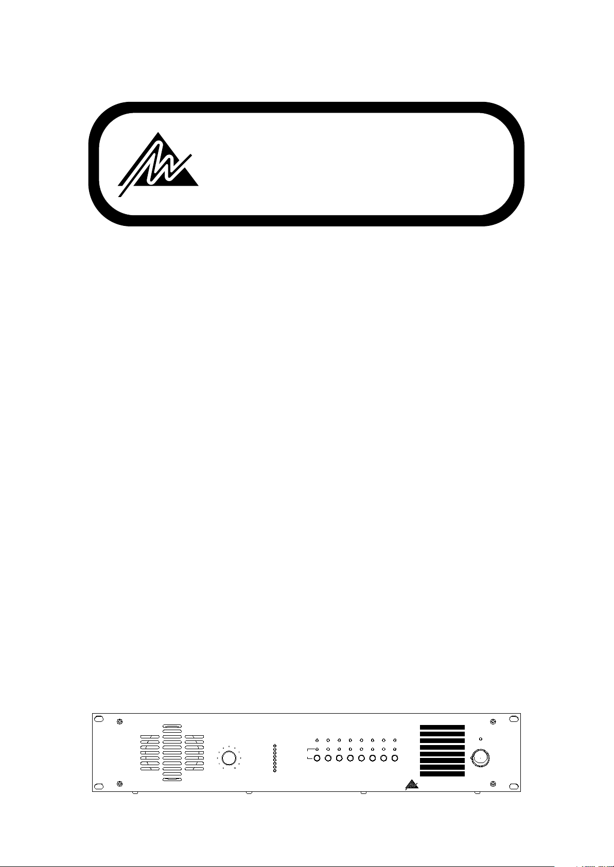
MP8
8 Zone Monitor Panel
INSTALLATION
AND
OPERATION
MANUAL
MONITOR SPEAKER
VOLUME
PROGRAM
LEVEL
SIGNAL
PRESENT
+3dB
0dB
- 3dB
AMPLIFIER
SELECT
- 6dB
- 9dB
-12dB
-18dB
-24dB
1 2
5
3
6
4
7
MP 8 Monitor Panel
AMPLIFIER 1
AMPLIFIER 2
AMPLIFIER 3
AMPLIFIER 4
AMPLIFIER 5
AMPLIFIER 6
8
AMPLIFIER 7
AMPLIFIER 8
Australian Monitor
INSTALLATION SERIES
ON
POWER
Page 2
Issue
Original
Copyright 14th April 2003
Rev A
14th April 2003
AUS, EUR, USA
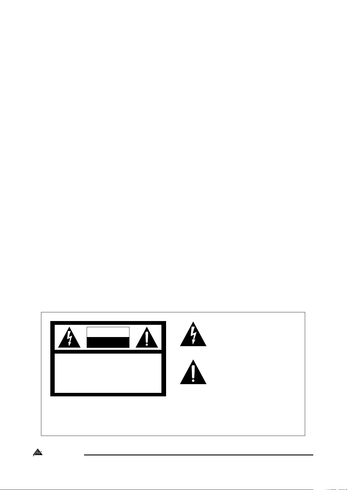
CAUTION: TO REDUCE THE RISK OF ELECTRIC SHOCK.
DO NOT REMOVE COVER (OR BACK).
NO USER-SERVICEABLE PARTS INSIDE.
REFER SERVICING TO QUALIFIED SERVICE PERSONNEL.
CAUTION
RISK OF ELECTRIC SHOCK
DO NOT OPEN
This symbol is intended to alert the user to the
presence of uninsulated “dangerous voltage”
within the product’s enclosure that may be of
sufficient magnitude to constitute a risk of electric
shock to persons.
This symbol is intended to alert the user to the
presence of important operation and maintenance (servicing) instructions in the literature
accompanying the appliance.
WARNING !
TO REDUCE THE RISK OF FIRE OR ELECTRIC SHOCK.
DO NOT EXPOSE THIS EQUIPMENT TO RAIN OR MOISTURE.
Australian Monitor
INSTALLATION SERIES
Caution:
To prevent electric shock do not use this (polarized) plug
with an extension cord, receptacle or other outlet unless
the blades can be fully inserted to prevent blade exposure.
To prevent electric shock, match wide blade of plug to
wide slot, fully insert.
2 3
Page 3

CONTENTS
Page
1. Introduction 4
2. Front Panel 5
3. Back Panel 7
4. Installation 8
5. Dimensions 9
6. Operation 10
7. Block Diagram 11
8. Specifications 11
Australian Monitor
INSTALLATION SERIES
Page 4

1. INTRODUCTION
MONITOR SPEAKER
VOLUME
PROGRAM
LEVEL
+3dB
0dB
- 3dB
- 6dB
- 9dB
-12dB
-18dB
-24dB
1 2
3
4
5
6
7
8
MP 8 Monitor Panel
POWER
ON
SIGNAL
PRESENT
AMPLIFIER
SELECT
AMPLIFIER 1
AMPLIFIER 2
AMPLIFIER 3
AMPLIFIER 4
AMPLIFIER 5
AMPLIFIER 6
AMPLIFIER 7
AMPLIFIER 8
INSTALLATION SERIES
Australian Monitor
The Australian Monitor Installation Series MP8 is a 2 RU monitoring panel that allows you to
monitor any of up to 8, constant voltage or low impedance speaker lines. This can be done
via the on-board 2.5" monitor speaker or via the 8 segment VU meter. The MP8 also provides
signal present LED’s for each amplifier as well as LED’s to indicate which amplifier is currently
selected for monitoring. The MP8 operates from either an AC/DC 12V-24V plug pack or via 24
VDC & boasts ample label space.
We thank you for choosing Australian Monitor Installation Series &, as with all our products, the
MP8 contains many clever features & is contractor friendly.
Australian Monitor
INSTALLATION SERIES
4 5
Page 5

MONITOR SPEAKER
VOLUME
PROGRAM
LEVEL
+3dB
0dB
- 3dB
- 6dB
- 9dB
-12dB
-18dB
-24dB
1 2
3
4
5
6
7
8
MP 8 Monitor Panel
POWER
ON
SIGNAL
PRESENT
AMPLIFIER
SELECT
AMPLIFIER 1
AMPLIFIER 2
AMPLIFIER 3
AMPLIFIER 4
AMPLIFIER 5
AMPLIFIER 6
AMPLIFIER 7
AMPLIFIER 8
INSTALLATION SERIES
Australian Monitor
5
6
8
1 2 3
4
7
9
2. FRONT PANEL
¬ Monitor Speaker:
A 2.5” speaker is located behind a cloth grille. No cleaning is required.
Monitor Speaker Volume Conrol:
This knob controls the volume level of the monitor speaker.
NOTE: The Speaker Volume Control does not affect the level of the VU indicator
nor does it affect the amplifiers or speaker lines that are connected to the
MP8.
® VU meter:
This meter indicates the output level of the currently selected amplifier. The 0dB level is
referenced to 100V. This is an RMS meter, not a peak meter.
¯ Selector Switches:
These switches select which amplifier is connected to the monitor and meter circuits. The
switches are mechanical interlocking push buttons, meaning that when one button is
pushed, the previously selected switch is mechanically deselected.
° Select Indicator:
This LED indicator will illuminate to show which amplifier is selected for monitoring.
± Signal Present:
This LED will light dimly when the signal from the corresponding amplifier reaches
approximately -24dB (6.3Vac) indicating signal is present and will get progressively
brighter with increased signal level.
NOTE: Signal present indication is irrespective of which amplifier is selected. This
indicator is a passive circuit across the amplifier input and will indicate
signal across each speaker line even when the MP8 is not powered.
Australian Monitor
INSTALLATION SERIES
Page 6

AMP 1 AMP 5AMP 2 AMP 6AMP 3 AMP 7AMP 4 AMP 8
INPUT FROM 100V LINE AMP.
+ ++ ++ ++ +
ZONE 1 ZONE 5ZONE 2 ZONE 6ZONE 3 ZONE 7ZONE 4 ZONE 8
OUTPUT TO 100V SPEAKERS
+ ++ ++ ++ +
24 VDC IN
12-24V AC/DC
TIP +VE
+
ENGINEERED BY AUDIO TELEX COMMUNICATIONS PTY LTD SYDNEY AUSTRALIA
² Labels:
This area is available to custom label the zones each amplifier is driving.
³ Power On LED:
This indicates there is power to the unit.
NOTE: When using 24VDC IN terminals the power LED will always be on.
´ Power Switch:
This switch switches power from the AC/DC plug pack input.
NOTE: When using 24VDC IN terminals the unit is on regardless of switch position.
Australian Monitor
INSTALLATION SERIES
6 7
Page 7

AMP 1 AMP 5AMP 2 AMP 6AMP 3 AMP 7AMP 4 AMP 8
INPUT FROM 100V LINE AMP.
+ ++ ++ ++ +
ZONE 1 ZONE 5ZONE 2 ZONE 6ZONE 3 ZONE 7ZONE 4 ZONE 8
OUTPUT TO 100V SPEAKERS
+ ++ ++ ++ +
24 VDC IN
12-24V AC/DC
TIP +VE
+
ENGINEERED BY AUDIO TELEX COMMUNICATIONS PTY LTD SYDNEY AUSTRALIA
3
12-24V AC/DC
TIP +VE
1
2
4
3. BACK PANEL
¬ Power Socket:
This 2.1mm socket accepts AC or DC voltage between 12V and 24V.
For DC, tip is positive.
24VDC In Binding Posts:
These binding posts provide connection for 24V emergency systems
and is not switched by the front panel power switch. The 24VDC IN
does not provide trickle charge facility.
® Input Terminal Strip:
Paired connection from each amplifier in the system. The label AMP
‘X’ corresponds with AMPLIFIER ‘X’ on the selector switches.
¯ Output Terminal Strip:
Paired connection to each zone speaker distribution, wired in
parallel with input terminal strip.
NOTE: The terminal lug accepts wire gauges from AWG22 (0.75mm) up to
NOTE: The MP8 will accept input from both constant voltage systems and low
AWG16 (1.5mm). Each terminal is rated at 15A/300VAC.
impedance systems or a mixture of the two.
Australian Monitor
INSTALLATION SERIES
Page 8

4. INSTALLATION
Wiring:
Connect the speaker output of the first amplifier to INPUT terminals labelled AMP 1,
maintaining correct polarity. Connect the speaker load for this amplifier to OUTPUT
terminals labelled ZONE 1.
Repeat for additional amplifiers and speaker loads.
Always use appropriate cable for amplifier to MP8 and MP8 to speaker wiring.
Power Requirements:
The MP8 can operate on the supplied plug pack and/or separate 24V DC power supply.
A NOTE ABOUT GROUNDING:
It may be necessary in some circumstances to ground the MP8 to eliminate noise
from the monitor speaker. This can be done using the negative terminal of the
24VDC IN binding post or by making sure that the chassis is electrically connected to
the equipment rack (which should be grounded).
A NOTE ABOUT SPEAKER ISOLATION:
When a zone is selected for monitoring it is isolated from the other amplifiers by
1kohm resistors. The negative input is also AC referenced to chassis ground with a
capacitor.
Australian Monitor
INSTALLATION SERIES
8 9
Page 9

5. DIMENSIONS
444.0mm [17.5"]
75.8mm [3.0"]
12-24V AC/DC
TIP +VE
ENGINEERED BY AUDIO TELEX COMMUNICATIONS PTY LTD SYDNEY AUSTRALIA
24 VDC IN
+
MONITOR SPEAKER
VOLUME
482.0mm [19.0"]
467.0mm [18.4"]
SIGNAL
PROGRAM
PRESENT
LEVEL
+3dB
0dB
- 3dB
AMPLIFIER
SELECT
- 6dB
- 9dB
-12dB
-18dB
-24dB
210.0mm [8.3"]
AMP 1 AMP 5AMP 2 AMP 6AMP 3 AMP 7AMP 4 AMP 8
+ ++ ++ ++ +
ZONE 1 ZONE 5ZONE 2 ZONE 6ZONE 3 ZONE 7ZONE 4 ZONE 8
+ ++ ++ ++ +
3
1 2
INPUT FROM 100V LINE AMP.
OUTPUT TO 100V SPEAKERS
MP 8 Monitor Panel
AMPLIFIER 1
AMPLIFIER 2
AMPLIFIER 3
AMPLIFIER 4
AMPLIFIER 5
5
6
4
AMPLIFIER 6
7
8
AMPLIFIER 7
AMPLIFIER 8
Australian Monitor
INSTALLATION SERIES
ON
POWER
88.0mm [3.5"]
25.0mm [1.0"]20.0mm [0.8"]
Australian Monitor
INSTALLATION SERIES
Page 10

6. OPERATION
The SIGNAL PRESENT LED’s give a continuous indication of the signal from each of the
eight connected amplifiers. Note that very low levels may not be detected.
To monitor a particular amplifier, SELECT the desired amplifier. The listening level may be
adjusted using the MONITOR SPEAKER VOLUME. The PROGRAM LEVEL meter gives accurate
indication of signal from the selected amplifier.
A NOTE ABOUT MONITORING:
It should be noted that adjusting the monitor speaker level control does not effect
the sound level in the selected zone and nor do the level indications indicate the SPL
of the speakers in any zone. The MP8 should be used to monitor an amplifiers output
signal quality and presence only and as such, it does not reflect the condition of the
actual sound output in any speaker zone.
Setting the level:
The monitor speaker level has been designed to accept a wide range of program levels.
Distortion may occur in the MP8 if the speaker volume control is set too high while the
amplifier is producing a high output, as indicated by the program level meter. Check the
setting of the level control and reduce if necessary. If distortion is still present, then check
amplifier operation and affected speaker lines.
Switching the Monitored Zone:
It is possible to select 2 amplifiers at once and monitor them simultaneously, however, this
is not recommended. Fusible isolation protection exists to protect both the external
amplifiers and the MP8.
Australian Monitor
INSTALLATION SERIES
10
Page 11

7. BLOCK DIAGRAM
8.SPECIFICATIONS
-Dimensions:
88.0 x 482.0 x 210.0 (HxWxD) mm
-Weight:
Net 4.0kg Shipping 5.4kg
-Power Input:
12-24V AC/DC
8VA max
-Standing Current (all voltages):
DC 40mA
AC 85mA
-Maximum Current:
12VDC 150mA
24VDC 225mA
16VAC 350mA
-Monitor Volume Levels:
Input for Max speaker output (10% THD)
Pot @ 1: -6dB (Ref 100V)
Pot @ 5: -14dB
Pot @ 10: -27dB
-Crosstalk:
-72dB @ 1kHz
-53dB @ 10kHz
-Signal Present Threshold:
-24dB (6.3Vrms)
-Meter Reference:
0dB 100Vrms
rms meter
-Speaker Terminal Cable:
AWG22 (0.75mm) to AWG16
(1.5mm)
11
Australian Monitor
INSTALLATION SERIES
Page 12

www.australianmonitor.com.au
Sydney (NSW & ACT Sales)
Private Bag 149, Silverwater NSW 1811
149 Beaconsfield Street, Silverwater NSW 2128
Melbourne (Vic & Tas Sales)
P.O. Box 131, Blackburn South VIC 3130
22/277 Middleborough Road, Box Hill VIC 3128
Brisbane (Qld Sales)
P.O. Box 871, Fortitude Valley QLD 4006
42 Commerical Road, Fortitude Valley QLD 4006
Adelaide (SA & NT Sales)
Ph: (02) 9647 1411
Fax: (02) 9648 3698
E-mail: nsw@audiotelex.com.au
Ph: (03) 9890 7477
Fax: (03) 9890 7977
E-mail: vic@audiotelex.com.au
Ph: (07) 3852 1312
Fax: (07) 3252 1237
E-mail: qld@audiotelex.com.au
P.O. Box 157, Hindmarsh SA 5001
31 Walsh Street, Thebarton SA 5031
Ph: (08) 8352 4444
Fax: (08) 8352 4488
E-mail: sa@audiotelex.com.au
Perth (WA Sales)
P.O. Box 404, North Perth WA 6906
299 Fitzgerald Street, West Perth WA 6005
Ph: (08) 9228 4222
Fax: (08) 9228 4233
E-mail: wa@audiotelex.com.au
Auckland (NZ Sales)
P.O. Box 512, Albany 1331
Unit B, 11 Piermark Drive, Albany 1331
Ph: (09) 415 9426
Fax: (09) 415 9894
E-mail: audiotlx@nznet.gen.nz
Export Sales
Private Bag 149, Silverwater NSW 1811
149 Beaconsfield Street, Silverwater NSW 2128
Australia
Ph: 61-2- 9647 1411
Fax: 61-2-9748 2537
E-mail: international@audiotelex.com.au
United States of America
Australian Monitor Audio Inc.
PO Box 3126, Lynnwood, WA 98046
E-mail: sales@australianmonitor.com
Ph: 425 673 5175
Fax: 425 673 7825
www.australianmonitor.com
12-24V AC/DC
TIP +VE
ENGINEERED BY AUDIO TELEX COMMUNICATIONS PTY LTD SYDNEY AUSTRALIA
24 VDC IN
+
AMP 1 AMP 5AMP 2 AMP 6AMP 3 AMP 7AMP 4 AMP 8
+ ++ ++ ++ +
ZONE 1 ZONE 5ZONE 2 ZONE 6ZONE 3 ZONE 7ZONE 4 ZONE 8
+ ++ ++ ++ +
INPUT FROM 100V LINE AMP.
OUTPUT TO 100V SPEAKERS
 Loading...