

Page 1
Australian Monitor
Introduction
Ktu
K snnlns LooP AMPLIFIERS
Australian Monitor is
the successful K-Series range, these amplifiers utilise
provide
system
detail
Hosting most of the features and
loop amplifiers offer some additional
up of an lnduction loop system.
These
to
whilst maintaining
include:
,
Additional
construction
strapping
features include:
for
connectors, massive
proud
a constant
lntemal
10dB into compression indicator
lnput Level
level
Dual
Low frequency output current limiting
Loop disable relay at turn on
Loop open / voltage too high indication
Binding Post and
Active
Signal Ground
ease
introduce
to
cunent into a single turn
total stability.
protection
limiter
Balanced lnputs
of
with 250mV threshold and
Control
output cunent indicators
Speakon
"LlFT"
Custom
servicing, well
heatsinking, Front to back cooling and a dual speed axial
you
to
circuitry, controls
for adjusting input signal for the ideal operating window
switch.
its range of lnduction Loop amplifiers. Modelled
networks of the K-series Audio Amplifiers the KLa
loop connections
designed
regulating high current
our unique impedance and
lnduction Loop, resulting in clarity and
and lndicators
panel
front
(and
indication)
-
heavy duty chassis, open modular
assist
to
indication
power
supply, lnput signal
phase
in the conect set-
sensing
fan.
on
Protection
over-voltage
Breaker,
The layout,
stability, reliability and longevity.
features include:
protection,
lndependent
grounding,
DC supply rail Fuses.
decoupling and componentry have been optimised to
RF interference suppression, Short-circuit
ltu
Mainrs inrush cunent
suppression, lnput muting at tum on, lnput
protection,
provide
Mains
the user with
Circuit
Austdlan Monitor
Page 2
KLa Loop Amplifiers 2
Front Panel
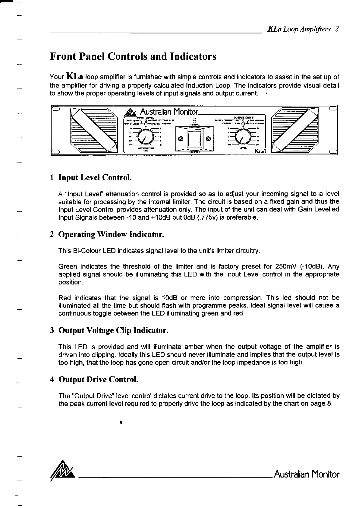
Your KLa loop amplifier is furnished with simple controls and indicators to assist in the set up of
the amplifier for driving a
to show the
1 Input Level
"lnput
A
suitable for
lnput Level
lnput Signals between
proper
Level" attenuation control is
Controls and Indicators
operating levels
Control.
processing
Control
provides
properly
by the internal limiter.
-10
calculated lnduction Loop. The indicators
of input signals
provided
attenuation only.
and
+10d8
but OdB
provide
and output current.
as to adjust
so
The circuit is based on a fixed
The input of the unit can deal with Gain
(.775v)
preferable.
is
your
incoming signal
visual detail
gain
and thus the
to a level
Levelled
2 Operating Window
This Bi-Colour LED indicates signal level to the unit's limiter circuitry.
Green indicates the
applied signal should be illuminating
position.
Red indicates that the signal is 10dB or more
illuminated
continuous
3 Output
This LED is
driven into clipping. ldeally this LED
too high, that the loop has
4
Output
"Output
The
peak
the
all the time but should flash with
toggle between the LED illuminating
Voltage
provided
Drive Control.
Drive" level control dictates current drive
current level required to
Indicator.
threshold
Indicator.
Clip
and will illuminate amber when the output voltage
gone
of the
open circuit
limiter and is factory
this
with the lnput Level control in the appropriate
LED
into compression. This led should not be
programme
green
should never illuminate and implies that
and/or the loop impedance is too
properly
drive the
peaks.
and red.
to the loop. lts
loop as indicated by the chart on
preset
for 250mV
ldeal signal level will cause a
(-10dB).
of the amplifier is
the output level is
high.
position
will be dictated by
page
Any
8.
/tu
Australlan Monitor
Page 3
5
Current Level
"Cunent
The
Indicator.
Level"
LED
provided
is
as indication
to show the
peak
KLa Loop Amplifier.s
cunent
in the loop.
3
KLa I -
KLa2 -
see chart for
6 Fault
Green
Green
3Amps,
=
5 Amps,
=
loop calculations.
/ Current Limit
This amber coloured
indicates
infrequent
illuminating
The
on the output.
7
On lThermal Indicator
This is
on and receiving
ln the advent
temperature
shut down and
has had a cool
suppression,
limiting of
flashing
of this
LED will also illuminate
a Bi-Colour
of a Thermal
of
of this LED
LED requires
LED which
mains
the amplifier
isolated itself
down
input muting
Red
=6Amps.
Red
10 Amps
=
Indicator.
LED will
the cunent
power.
period
illuminate when
into the load
peaks
on
the output drive
with other
will normally illuminate
Overload this LED will tum
has exceeded
from the loop.
faults such
the unit
and the
loop relay isolation
load cunent exceeds
and will flash
at lower
a safe level
The fan will
frequencies
to be reduced.
as blown negative
green
red indicating
of operation
continue to
with
quite
is
and indicates
will restart automatically
will be bypassed.
a safe value.
programme peaks.
acceptable.
rail fuse and short
that the amplifier
that the intemal
and that the amplifier
run and once the
providing
inrush
The led
Constant
circuits
operating
amplifier
current
The
is
has
8 Power
Press the switch down
should
ofr.
At tum-on
Switch
be the last
a number of events
a)
Mains inrush cunent
b) A relay isolates
c) lnput signal to
for
ON and up for
piece
of equipment
happen during
suppression is
the lnduction
the main amplifier
Loop until the amplifier
OFF.
you
tum on and
the
provided,
is muted
Like
any other
power-up
(>30d8)
power
the first
of
has established
for approx'2
piece
the amplifier.
amplifier in
of equipment
itself,
to 3 seconds.
any system it
you
tum
/tu
Aushalian
lYonitor
Page 4

Rear Panel
KLa Loop Amplifters 4
,//Ll< r-;a*
l"^ffi.*.74rz
I\lll sm.G.xmd
I Balanced Input & Strapping
A female 3-pin XLR connector is
provided
strapping/looping
Pin allocation is: Pin-l
2
Signal Ground
When this switch is engaged it disconnects signal
be used when
as a strapping connector wired in
"HUM"
The
between
Lift
amplifier
multiple amplifiers.
Signal Ground,
=
Switch
is caused by earth loops or stray magnetic fields.
should
\
ro7'e!.o/.oh,/
Connection
provided
Pin-2
be tumed
Loop Outputs.
Your Kla Loop Amplifier is
cunent Binding Post outputs are
The Speakon connector is wired 1+
provided
provided
with 2 options for output termination of the loop. Heavy
as well as a Neutrik
positive
=
Mains Lead
as input connection. A male XLR connector is
=
parallel
(reverse phase),
Cold
ground
with the input XLR allowing
phase).
(in
=
Hot
Pin-3
from the amplifier. lt is intended to
off before engaging this switch.
& 1-
negative.
=
"Speakon"
connector.
Your amplifier is supplied with a heavy duty mains lead
mains supply voltage marked on the rear
coloured in accordance
are
Brown
Mains
A
amplifiers
current internal fault or in continued overload conditions,
"push
Circuit
to reset" thermal circuit breaker is
power
Breaker
supply.
the
with
Active, Blue
=
Your
will isolate the
lt
following
unit
panel
Neutral, Green/yellow = Earth.
=
must always be earthed!
"active"
your
of
code.
supplied to
mains conductor in the event of a
D.C. Rail Fuses
"fast
3AG
rails for
stage.
The
bloy/' type fuses are
your
fuses must be replaced with the same type fuse.
amplifiers output stage. These fuses
provided
KLal
and are in series with the
Amps, l(La2
=
8
='10
(power
amplifier. The wires in the mains lead
provide
cord) appropriately rated for the
provide
Amps.
overall
positive
overall
protection
and negative supply
protection
of the output
of
your
high
/tu
Aushalian
Monitor
Page 5

KLa Lpop Amplifiers 5
To
set up
Once all connections have
I Make sure all the
2 npply signal
Turn up'INPUT
3
and red illuminations.
your
(applied
KLa Loop
been made:
controls are down before
signal should be
LEVEL'knob until
Amplifier:
you
tum
gain
levelled
'OPERATING
the amplifier ON.
and be around odB
WINDOW"
LED is flashing between
NOTE: The red LED should not be on constantly, but should flash with
4 Tum up
KLa 1
KLa2
NOTE: These
5 Use
'OUTPUT
Green
Green
a field strength meter or loop listening device to monitor level and coverage in the loop.
DRIVE" control to the desired cunent level.
3Amps,
=
5 Amps,
=
LEDS are to illuminate on
Red = 6 Amps.
Red
10 Amps.
=
peaks
only.
-
0.775 volts
programme peaks.
)
green
-
The do's and don'ts
There are a few
As there is a strong field radiating from the cable it can interfere with other
your
thus
loop
precautions you
should be restricted
need to consider when
(as
far as
possible)
installing
to a defined
your
lnduction Loop System.
listening area.
Do:
Always ensure the installation of
As far as
above or below this is acceptable but
Run balanced signals / cables wherever
possible
have
your
your
loop at the same elevation as
is in accordance
Loop
cunent drive
more
possible.
may
with wiring regulations.
the listening
be
required.
position,
Do Not:
Do not install the loop with other cable runs - never run the loop cable in
and always cross other cables at right angles.
Do not run
performance.
your
Loop cable
conduit
in
or in / or near shielded trays as this may effect its
parallel
electronic equipment
1 to 2 metres
with other cables
'
Do not have dynamic type microphones, which may be a
the loop.
the system.
I
The coil
may
pick
up the radiated field from the
part
of the signal source, inside or
loop and cause feedback to occur
near
Do not run unbalanced signals / cables as they may be affected by the Loop and cause
feedback.
/tu
Ausbdan Monitor
in
Page 6

KLa Loop
Amplifiers 6
Why An Induction
Usually,
The system is driven by an amplifier
encompassing
radiated field induces cunent
of the hearing impaired.
Because a length of wire is used as the load from which the signal is radiated, it makes special
demands
The wire will exhibit a very low impedance at low frequencies and exhibit a higher impedance as
the frequency rises. To maintain
bandwidth)
are a constant voltage type and will not drive an lnduction Loop
output is constant
will reduce as the frequency
The
an lnduction
on
the amplifier driving it.
you
graphs
below show
Loop system is installed as an aid to
the listening area. A field is radiated from the cunent
must maintain a constant cunent into the load. Normally encountered amplifiers
(regardless
Loop system.
provide
which can
to flow
of
rises.
the transfer characteristic of a Klal
(more
constant radiation from the
a
load variations) and fidelity will be lost in the system as radiation
often than not) in a
provide
a constant cunent into a wire loop
audio for
"T-Coil"
piece
System
into 50
iii
hearing impaired.
the
flowing in the loop, and this
in the hearing aid device
of wire
metres of 2.00 mm2
(through
properly
the audio
as their voltage
cable.
'-i
0t(
OutDut Voltase Vs Freouencv
graph
The above
voltage variation of e KLal required to maintein e
constant current of 5 amDs into the lnduction
This Loop exhibits an impedance of 0.5 ohm at 200H2 and
Power into
type amplifier diving the same loop at 5 amps
Also the amplifier is driving a virtual short circuit for the lower frequency spectrum
invoke
the
protection
(lowest
loop
circuitry to continuously operate in
Two traces are shown
which
show a fully- compensated high frequency response. This adjustment would normally
factory
not
allows for
pres'et (no
properly
the
compensation), but could become useful in circumstances where the
calculated.
__ll
trace) shows the output
2O0Hz
@
above.
higher frequency
12.5 VA but
=
The KLa Loop Amplifiers
t* l0
LooD.
@
@
response
lo t(
Current OutDut Vs Freouencv
graph
The above
Frequency Response relative to cunent output of the
KLal. odB reference
an
impedance
10kHz the
200H2 would be down 1$dB
constant voltage type amplifiers.
power
(lowest
trace) shows the
5amps @ 200H2.
=
of 4 ohms at lokHz.
1O0 VA. A constant voltage
=
10kHz.
@
and thus would
have an internal adjustment
to be extended. The upper trace on the
\ \i
vn
.,*
*r0
(RV-1)
graphs
be left at
loop
i
\i
\
' '"']
the
was
The hearing impaired can detect more detail in the
this reason lnduction Loop
have a built in limiter to further reduce transients in the applied
Systems
should be fed with
programme
gain
/tu
if dynamic range
levelled signal. The KLa
programme
source.
is reduced. For
Ausbalian Monitor
amplifiers
Page 7

KLa Loop Amplifiers 7
Calculating
The following
installation. You
reguired and
information is
to select the appropriate
H|GH cuRRENr TERMTNA-floN
OUTPUT TFRMINAI S :
will need to know the size of
Induction
the
')c-
provided
Loop.
as a
gauge
LOOP
",o""
guide
for the
your
of
the wire for the loop.
I
-
proper
loop to ascertain the
calculation of
your
lnductive Loop
peak
drive cunent
LENGT
H
I
FEED
LOOP
PARALLELING
IIF REOUIRED}
First we need to calculate the Peak cunent required in the loop. The lnduction Loop Peak
Chart
cunent
(page
8) shows the relative cunent required for different size loops
(Ampere)
curve. lf
your
LINKS
.-
loop is a circle, simply approximate it to a square.
BREADIH
-.....*
-
Pick the closest
Cunent
Then we need to determine the length of cable required
perimeter
the
Now we need to calculate the
of the loop.
To this add the loop feed distance, for a total wire length.
gauge
of the wire. lt is recommended that the
(length
of the loop is between 0.5ohm and 1.0 ohm. We also recommend that
rating of the cable is well above the
insulation is of a heavy duty type with a
To help reduce the variation in wire
heavy duty figure-8 cable with a termination block
allow
you
parallel
to
the conductors
Stranded
1.00
1.50
2.OO
2.50
-3.00
32tO.20
30/0.25
40t.o25
50/.025
63tO.25
peak
cunent required into the
good
dielectric strength and
gauges
if the resistance of the loop is too high.
needed to satisfy every loop we suggest running a
(as
shown in the above diagram) which will
copper conductors to 836360
17
16
14
13
12
For example: A loop that is 15 metres by 40 metres requires a
perimeter
To achieve a D.C. resistance of between 0.5 and 1.0 ohms we would need to use 12 AWG wire
which will
required
amps.
110 metres and the loop feed is 10 metres long, thus 120 metres of cable is required.
=
give
us 0.72 ohms total D.C. resistance and a cunent rating 2.5 times the
(20
amps).
Paralleling 16 AWG wire would
give
us a similar result
+
breadth)
x 2.
this
total D.C.
you
ensure
(>2
loop
high thermal capacity.
-
1991
1.85
1.26
0.98
0.76
0.60
peak
times) and
cunent of 8 amps. lts
0.756 ohms for 18
@
give
will
resistance
cunent
the
that
6
I
11
15
20
peak
cunent
us
the
ltu
Aushalian
Monitor
Page 8

oo
,c
$
*
\
$
o
\)
q
tt
16l
-cl
ol
trl
0rl
H
=l
ol
-Yl
cl
0rl
o-l
ol E^
!l F=
cl
€l E'
=l
El
El
S'
:t\
d
.z@
(u
oro
(!
6r
t
o
t N o
oooNr{(\r.i6t
a.l Fr
'lE'l
t(5v
url
S=9ocoNo.otorNre
(.
!t a{
o
o 6 €
E
o
-c
!
o
o
(n
CL
o
o
J
dccr
o(Jo
I
J(5
r0)
lfll
tt
!t
U'
E
o
CL
E
.r<
d
o
tt>
ao
lo t N
o
o
E
o
-c
o:
th
gv
-c
I
E tD
F
-
-E'
o
: ou
o !s
o
o
a
o
h oh
-
=
E
&
cL
5
o
: :s)
J(JE
s
o
o
o
0
19
0
o
E EI
c
o(I'o
bat
3
bE
E s\
a
eE
oct
-
aA
E
q
.ES s=
v_
.n
3 cb 5E,
85
-9
lo
-
b 9o
fr tE
!
E
:-
=
o
o E-c
-
E
o
b
=
t 9o
E
E
o oE
E
(i
.y.
E <.E
(L
9E
oo
cx
'?
c
E
o
o
o
F
,4
(5
oci
Fl
uo
=v
3U
E'=
hs
*tD
ECL
fi€
bP
lo
pE
*q
-O
p
-E
g+
oQ
gE
CD
-c
;_U
o.=
EO
oE
(It
(Y
> r,.j
e>
.ct
-c
o=
gH
.co
o.E
tE
EE
-o
31
o*
id<
E
Ul
..i
€
C
o
=
c
to
E
g
=
ru
 Loading...