

AUSTRALIAN MONITOR AM2200NG, AM2600NG Installation And Operation Manual
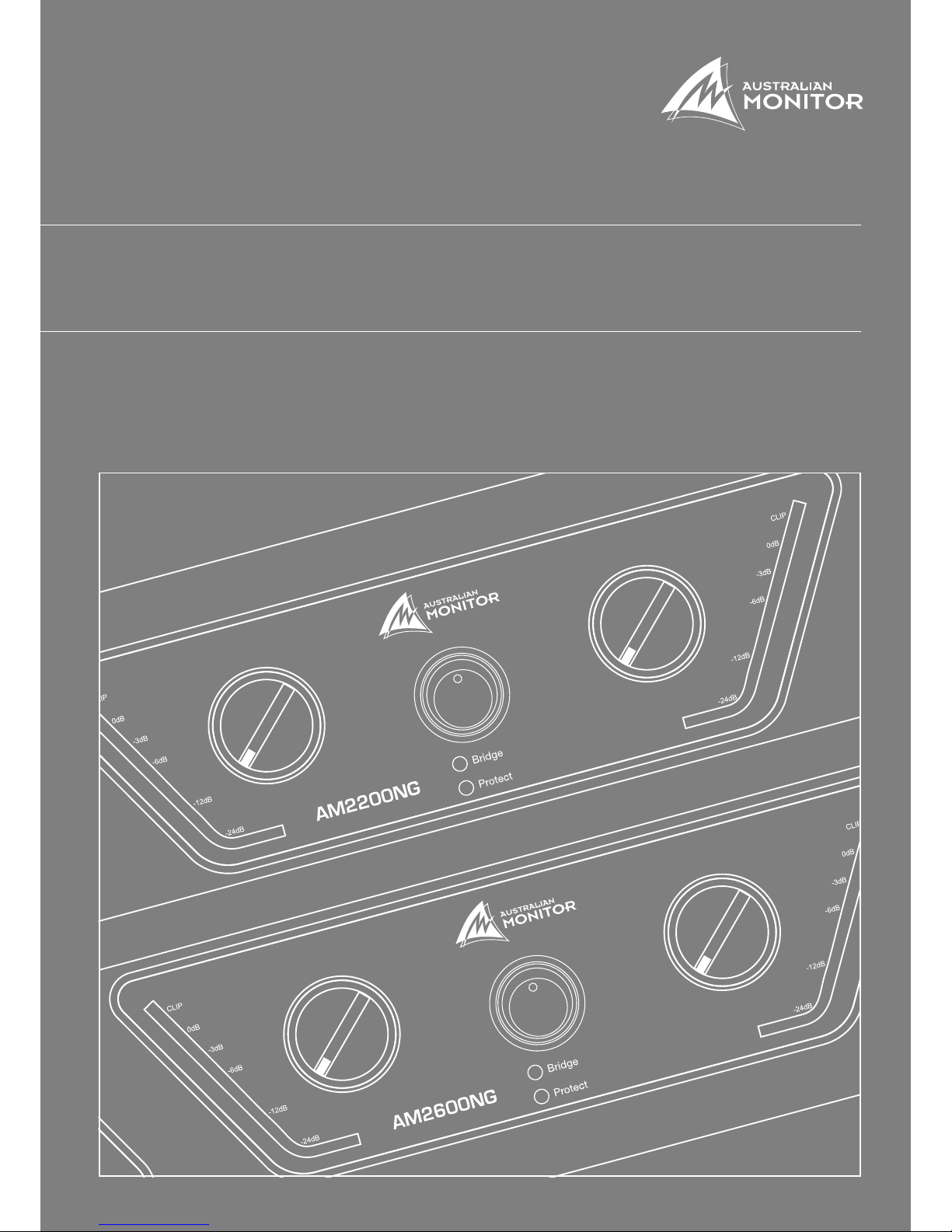
AM2200NG & AM2600NG
INSTALLATION AND OPERATION MANUAL

1. Save the carton and packing material even if the equipment has
arrived in good condition. Should you ever need to ship the unit, use
only the original factory packing.
2. Read all documentation before operating your equipment. Retain
all documentation for future reference.
3. Follow all instructions printed on unit chassis for proper operation.
4. Do not spill water or other liquids into or on the unit, or operate
the unit while standing in liquid.
5. Make sure power outlets conform to the power requirements listed
on the back of the unit.
6. Do not use the unit if the electrical power cord is frayed or broken.
The power supply cords should be routed so that they are not likely
to be walked on or pinched by items placed upon or against them,
paying particular attention to cords and plugs, convenience
receptacles, and the point where they exit from the appliance.
7. Always operate the unit with the AC ground wire connected to the
electrical system ground. Precautions should be taken so that the
means of grounding of a piece of equipment is not defeated.
8. Mains voltage must be correct and the same as that printed on the
rear of the unit. Damage caused by connection to improper AC voltage
is not covered by any warranty.
9. Have gain controls on amplifi ers turned down during power-up
to prevent speaker damage if there are high signal levels at the inputs.
10 Power down and disconnect units from mains voltage before making
connections.
11. Never hold a power switch in the “ON” position if it won’t stay
there itself!
12. Do not use the unit near stoves, heat registers, radiators, or other heat
producing devices.
13. Do not block fan intake or exhaust ports. Do not operate equipment
on a surface or in an environment which may impede the normal fl ow
of air around the unit, such as a bed, rug, weathersheet, carpet,
or completely enclosed rack. If the unit is used in an extremely dusty
or smoky environment, the unit should be periodically “blown free”
of foreign matter.
14. Do not remove the cover. Removing the cover will expose you
to potentially dangerous voltages. There are no user serviceable
parts inside.
15. Do not drive the inputs with a signal level greater than that required
to drive equipment to full output.
16. Do not connect the inputs / outputs of amplifi ers or consoles to any
other voltage source, such as a battery, mains source, or power supply,
regardless of whether the amplifi er or console is turned on or off.
17. Do not run the output of any amplifi er channel back into another
channel’s input. Do not parallelzz or series-connect an amplifi er output
with any other amplifi er output. Australian Monitor Inc is not
responsible for damage to loudspeakers for any reason.
18. Do not ground any red (“hot”) terminal. Never connect a “hot” (red)
output to ground or to another “hot” (red) output!
19. Non-use periods. The power cord of equipment should be unplugged
from the outlet when left unused for a long period of time.
20. Service Information Equipment should be serviced by qualifi ed service
personnel when:
A. The power supply cord or the plug has been damaged.
B. Objects have fallen, or liquid has been spilled into the equipment
C. The equipment has been exposed to rain
D. The equipment does not appear to operate normally, or exhibits a
marked change in performance
E. The equipment has been dropped, or the enclosure damaged.
THIS SAFETY INFORMATION IS OF A GENERAL NATURE AND MAY BE SUPERSEDED BY INSTRUCTIONS CONTAINED WITHIN THIS MANUAL
IMPORTANT SAFETY INFORMATION
PAGE 3AM2200NG & AM2600NG INSTALLATION AND OPERATION MANUAL
Congratulations on choosing Australian Monitor for your professional
amplifi cation requirements.
The AMNG Series Audio Power Amplifi ers embrace all aspects of a professional
tool exhibiting quality, reliability and longevity. The visual appearance,
mechanical, electrical and sonic parameters have been optimized using our
dedicated manufacturing process.
The AMNG Series amplifi ers are Should be “2RU (3.5” or 88mm) high, 19”
(482mm) wide” rack mountable units.
Each channel of the amplifi er comprises a balanced active input with buffered
attenuation through to the drive stage in turn feeding a fan-cooled output stage.
The amplifi er operates from a high current-capable switch-mode
power supply.
These amplifi ers have been specifi cally designed to deliver their high power
output with minimal distortion, and provide the critical degree of control required
by your speakers at high duty cycles for extended periods.
AUS, EUR, USA
Copyright 1st August 2008
Rev A: 01/08/08
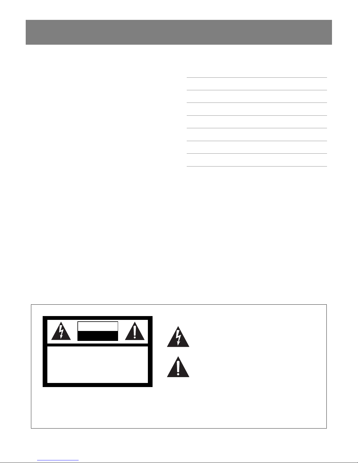
This symbol is intended to alert the user to the presence of uninsulated
“dangerous voltage” within the products enclosure that may be of suffi cient
magnitude to constitute a risk of electric shock to persons.
This symbol is intended to alert the user to the presence of important
operational and maintenance (servicing) instructions in the literature
accompanying the appliance.
To prevent electric shock do not use this (polarised) plug with an extension
cord, receptacle or other outlet unless the blades can be fully inserted to
prevent blade exposure. To prevent electric shock, match wide blade of
plug to wide slot, fully insert.
Caution:
CAUTION
CAUTION: TO REDUCE THE RISK OF ELECTRIC SHOCK,
DO NOT REMOVE COVER (OR BACK),
NO USER SERVICEABLE PARTS INSIDE,
REFER SERVICING TO QUALIFIED SERVICE PERSONAL.
WARNING!
TO REDUCE THE RISK OF FIRE OR ELECTRIC SHOCK
DO NOT EXPOSE THIS EQUIPMENT TO RAIN OR MOISTURE.
RISK OF ELECTRIC SHOCK
DO NOT OPEN
INTRODUCTION AND CONTENTS
INTRODUCTION 3
FEATURES 4
PROTECTION FEATURES 5
CONTROLS, CONNECTORS & INDICATORS 6–7
INSTALLATION 7–8
OPERATION 9
MAINTENANCE 10
SPECIFICATIONS 11

PAGE 4 AM2200NG & AM2600NG INSTALLATION AND OPERATION MANUAL
FEATURES
> Custom designed, 2RU heavy duty steel chassis
> Front carry handles
> Symmetrical layout – even-weight distribution
> Class G operation
> High effi ciency switch mode power supply
> Effi cient front to back cooling
> Variable speed axial fans
> Balanced inputs and buffered attenuators
> Input signal strapping (loop through) connectors
> Suppression of inrush current at mains turn-on
> Input muting at turn-on
> Input overvoltage protection
> Radio-frequency interference suppression
> Short-circuit protection and indication
> High overload mains breaker
> Thermal sensing
> Signal ground lift switch
> Built in limiter circuit
> Stereo, bridged or parallel operation
> Binding post and 4 pole speaker output connection
> VU meter
> Output clip indication
> Multi-role output fault indication
> High-quality, close-tolerance components throughout
> Lightweight
PROTECTION FEATURES
 Loading...