

Page 1

THE
CASSELL.BOOK
AUSTIN
A 35
OF
(1957-9)
THE
Page 2
CA
SSELL
B Y
ELLISONHAWKS
1. The Cassell Book
2. The Cassell Bookofthe A ustin T en (1939-47)
3.
Th
e Cassell Bookofthe Fo
4. Th e Cassell Bookofthe
5. The Cassell Book
6. Th e Cassell B ook
7. Th e Cassell Bookofthe F
8. T he Cassell Book of the
9. The Cassell BookoftheAustin
10. Th e Cassell Book
11. The Cassell Book
12. Th e Cassell Bookofthe M orris M inor (Series
13. Th e Cassell Bookofthe A ustin A 35 (1957
14. Th e Cassell Bookofthe
Th
e Cassell Bookofthe Vauxhall Wyve rn (19
16.
BYIAN NICK
15. The Cassell Book of the Hillman M inx
OLS
MOTORING
of
the
Austin
rd'Prefect'
Ford'
of
the
Ford'Popular'
of
theAustin A 40 Somerset (1952
ord'
Ford'
of
the
Ford'
of
the Standard E ight (1953
Ford'
SERIES
A 40 Devon (1947
A nglia ' (to 1953)
Consul ' (1951
Zephyr' and ' Zodiac'(1951
A30
•Seven ' (1951-6)
New A ng
New Pref
(1938
-53)
(from 1953)
-6)
lia'
(1953-7)
-5)
MM)
-9)
ect'
(after 1953)
51-
-52)
7)
-4)
-6)
The Cassell .Book
of
the
AUSTIN
(1957
by
ELLISON HAWKS
A35
-9)
CASSELL LONDON
Page 3
CASSELL & COMPANY LTD
35
Red
Lion
Square.London
and
at
MELBOURNE•SYDNEY
JOHANNESBURG•AUCKLAND
© Ellison
First
published 1960
..'
TORONTO•CAPE
Hawks
13
1960
wei
TOWN
II
III
IV
V
VI
VII
INTRODUC
FOR
THE
GENERAL
AND
TYRES
STEERING
SUSPENSION
BRAKING
ENGINE
CONTENTS
ING
THE
BEGINNER
MAI
NTEN
GEAR
SYSTEM
AUSTIN
ANCE;
\
PAGE
A35
I
9
BODY,
WHEELS
29
5
I
59
66
80
Butler
Set
and
Printed
& Tann er
in 10
pt.
in Great
Ltd.,
F.1259
Old
Britainby
Frome
Style
and
London
CARBURETTOR
VIII
FUEL
IX
COOLING
X
TRANS
XI
ELECTR
X
II
LUBRICATION
XIII
RECOMMENDED
FAULT
WIRING
INDEX
PUMP
SYSTEM
MISSION
ICAL
FINDING
DIAGRAM
SYSTEM
LUBRICANTS
CHART.
I06
n6
I25
I39
I 55
I93
2
I7
2I8
220
223
v
Page 4
PREFACE
HE
PURPOSE
simple language howthe owner-driver may
T
thebest
The
tempt
saryifthe
reduces efficiency
to deteriorate,
probable. The effici
life of any car are determined by the
Thi
appe
tively small
first-class
scribe to
Minor running
to time.
is
very
h
ave
small routine
Detailed instructions are given so
hecarried
devoted to overhauling to
mechanically-minded owner.
necessary, however,itis generally advisable to allow
local Au
facilities to
familiar
failure
give a course of
possible satisfaction from his Au
inherent
owners to neglect
best performance is to be
thusrend
s book is
arance of his car,
been avoided
and
writt
amount
ord
er.
the
' DoitYourself ' vogue .
The
old
true, for neglect
attention.
out
regularly
stin
dealer to do
handl
with
all
suggest remedies.
OF
THISBOOK
reliability of mod
the
and
causes
ering a breakdown onthe
ent
running, reliability
en for
the
and
of time necess
The
jobs involved are for those who sub-
adjustments
prov
erb
that'astitchintime
may
had
the
and
the
the
e such jobs. His staff is thoroughly
Austin
models,
training
ern
routinemaint
both
appe
owner who
who is able to devote
may
lead to expense
owner been familiar
thoroughly. A section has been
extent
When
heavy
can
The
and
vn
is to describe in
stin
cars
obt
arance
attent
arytomaintain
be required from
that
possiblebythe
extensive
work. He has
diagnose
Austin Motor Co.
instru
ction to selected
A35.
may
sometimes
enance so neces-
ain
ed. Neglect
and
mechanism
road
and
ion given to it.
takes
pride in
saves
that
with
lubrication
attention
symptoms
length of
the
average
obt
ain
mor
the
relait in
time
nine'
might
some
may
your
better
Ltd.
e
is
of
Page 5

Vlll
mechanics from dealers' staffs,
th
make use of
Ano
ther
gained conside
Naturally, it
part
s are used when necessary.
A few readers
is elemen
e expert knowledge
point to bear in mind isthatthe Comp
rab
str
esses
may
tary.
Ex
PREFACE
and
owners are advis ed to
thu
s gained.
any
has
le experience from years of research.
that
only genuine Austin replacement
feelthat
perience shows, however, that often
some ofthe information given
the
minor point isthe one that is overlooked, due to lack of
kn
owledge of its imp
atur
ticular fe
delay on
e. This can give rise to inconvenience due to
the
road, as well as expense in
This book is
who have no responsibility for it. At
would tender my
ha
ve given, and for supplying illu
data
.
Victoria H ouse.
Southport
"
ort
ance or
unf
amiliarity with a
upk
not
publishedbythe
th
anks tothem forthe assistance they
Austin Motor Co. Ltd.,
th
e same time I
str
ations
and
ELLISON
par
eep.
technical
H AW KS
CHAPTER I
INTRODUCING THE AUSTIN A35
HE AUSTIN A35 is another
a popular li
-
T
port
at low-
dat
e developments,italso has thecommodious luggagespace
so necess
elli
pti
c leaf-springs at rear,
ght
run
ary
car designed to give comfortabletrans-
ning cost. Equipped withthe most up-to-
for
tour
ing. Suspension incorporates semi-
out
and
independentfr
standing example of
ont
wheel
coils and wishbones at front. The driver has a clear view
th
e road ah ead,
of
Th
ere are two touring models
door saloons, and
and
Coun
trym
Mechanical design follows typical Austin
th
e car is simple to
can
be relied ontogive many years of care-free motoring.
Dri
ver's bucket seatis adjus
passenger's se
m
ents
of individual drivers and passengers and ensuring
thatlong-distance
and
threeoth
an.
maint
attothr
trav
controls fall readily to hand.
-th
e two-door and four-
er types
-th
e A35 Van , Pick-up
pr
actice in th
ain. Construction is suchthat
tab
le to five positions and
ee positions,
thu
s meeting require-
elling imposes a minimum of
at
it
fatigue.
Once
the
car is in use it isthe responsibility ofthe owner
tte
to keep it in good condition by careful a
tion and m
bri
efly in
aint
enance.
the
general specification given below.
Th
e main compon
ntion to lubrica-
ents
are described
Engine
Engine, identical in all models, is of
our-str
cylinder f
stroke 3-00in. ('76 mm.).
giving 34 b.h.p.
oke type. Bore, 2'48 in. (62'9 mm.) and
Capacity:
at
4,750 r.p.m. with a maximum torque of
50 lb. zft. at 2,000 r.p.m. Compression r
Cylinders are cast en bloc and, with
crankcase, provide a rigid mounting for the
beatings 'carrying
construction ensures
th
e counterbalanced crankshalf. This
the
least possible vibration.
the
usual four-
57'82 cu. in. (948c.c.)
atio:
upp
8'3 to
er half of the
thr
ee main
I.
A detachable cover gives ready access to overhead-type
I
Page 6
z
THE
BOOK OF
THE
AUSTIN A35
push-rod operated valves. Oil seals are fitted to prev
reaching
is driven
rubber ins
correct chain tension. The overhead valves
screwed rocker adj
mechanism is lubri
adjustment to a minimum.
lubric
th
e combustion heads by wayof
the
The camshaft , which is on the near side of
by
a duplex roller chain.
ertinth
atedund
The overhead
e sprocket to ens
ust
ment. The totally enclosed valve
cat
ed fromthe engine,thus r
er pressure fromthe oil
-va
lve rockers have a passage along which
It
incorpo
ure
silent running and
Th
e rocker shaft bearings are
pum
valve guides.
th
e engine,
rat
es a special
hav
e a simple
edu
p.
oil is fed to an outlet at the spherical ball-end, this l
fi
tting
rod. Oil at
as it is delivered
cleara nce' purposely provided between
and
intothe correspondingly shaped end of the push
thi
th
e rocker
s point n
tip
atur
ally obviates wear
und
er pres
sure,it
th
thu
s minimizing valve noise.
but
takes up the
e end ofthe valve
The four I-section connecting rods carry gudgeon pins
locked in
pin
eyes,
c
are
permit oil to reach
adequate supply of
th
s are
e little-end eyes by clamp bolts. Asthegudgeon
not
itisunn
free to
ecessary to provide circlips or
turn
in the connecting-rod
of endwise pin movement.
Th
e big-end bearings areprovided with small h
th
e cylinder walls,
lubricant
und
er all operating conditions
thu
littl
pad
s to take
<;>l
s assunng an
and particularly when th e engine is cool.
The dish-he
aded
pistons are of a special aluminium alloy
with alumite sur face to ensure efficient lubrication,
skirts being of
upp
ermost is a
are taper
oil-con
tro
Lubri
cati
type oil
pump
meshing gears driven from
passed
of
r
choked,
int
lost.
the
throu
the
engine
eturn
s to
the
erru
pted
Inst
filter would be by-passed.
the
split type. There are four rings :
plaiD;
compression rings, and
compression ring, the second .and .thlrd
th
e bottom n ngISan
lled slotted scraper ring.
on by pressure is developed by a submerged-
situated in a housingthatcont
the
camshaft.
gh an external filter
and
cleaned by a filter element before It
the
sump. Should this filter become completely
mountedonth
:=ti?-
s two
OllI
Sconstantly
e
oil flow tothe various bearings would
althoughthe
eadofth
e oil passing
purp
ose ofthe filter would be
throu
gh it to be cleaned,
ent
oil
cing
att
er
also,
sma
ll
e-end
es to
th
e
~h
e
int
er-
offsi~
e
not
be
INTRODUCING T
Oil is also supplied
main
bearings, big-end bearings, camshaft, and overheadvalve gear. A special a
camshaft bearing to provide oil to
pump
itself
has
a filterthat
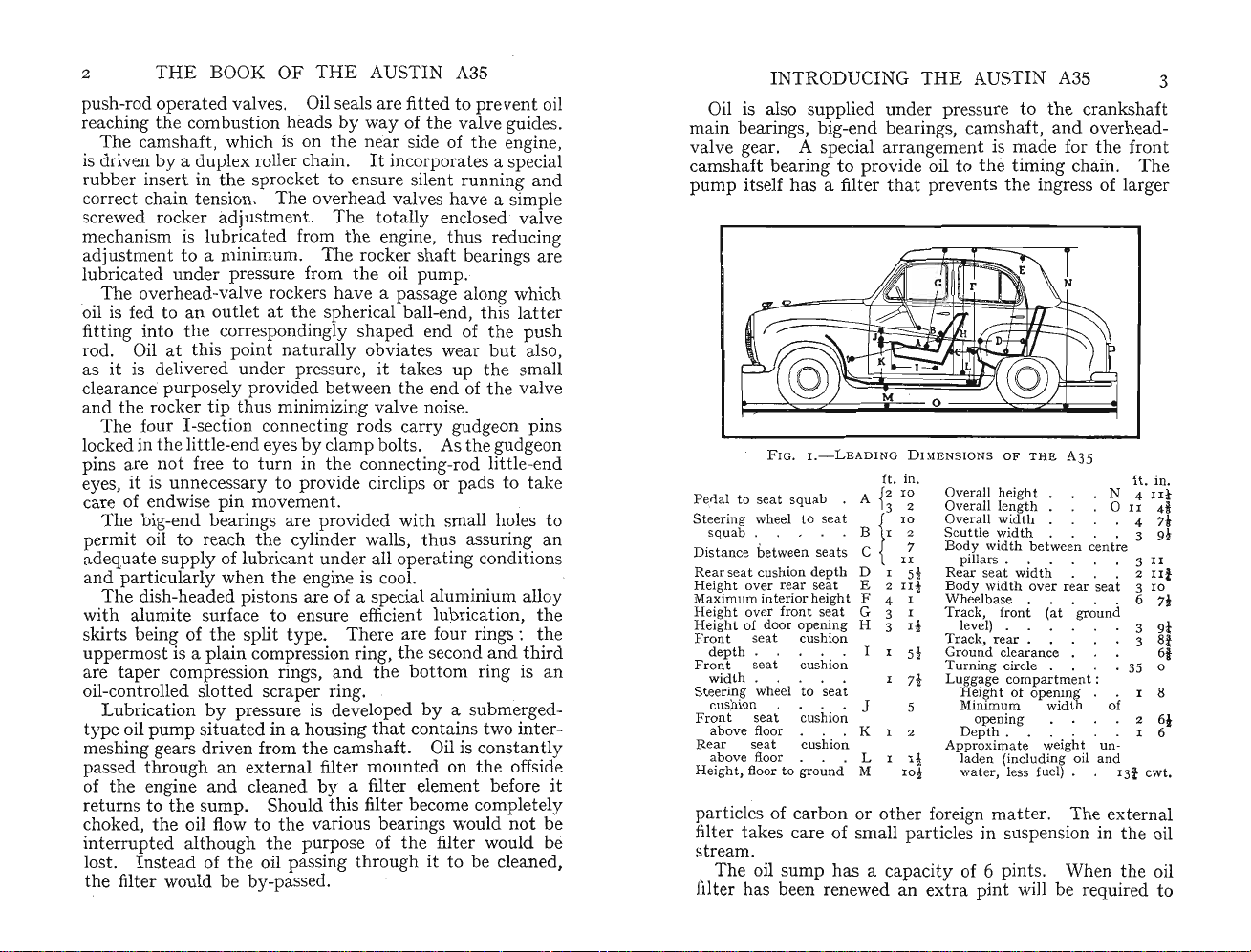
FIG.I.-LE ADING
Pe,rial to sea t
St
eering wheel to seat t
sq
uab
Distance be tween sea ts C I
Rear
sea t cushion
Height over r
Maximum int erior height F 4 I
Height
Heightof door
F
ron
t seat cu
depth . .
Front s
width . . . . .
Steerin g wheel to
cushion . . . . J
Front
abo ve floor . , . K
Rear
above
Height
squa
b .
A
. B I 2
dep
th D I
ear
seat E 2
over fron t
eat
seat cushion
seat cushion
floor . . . L I I!
, floor to
sea
opening
shion
cushion
seat
ground
t G 3 I
H 3 I!
I I
M
particles of carbon or
fi
ltertake
s care of small particles in suspension inthe oil
HE
AUSTIN A35
und
er pressure to
rra
ngement is made forthe front
th
prev
entsthe ingress of larger
DIM
ENSIO NS
ft . in .
2
10
{
3
other
Overall heig
Overall length 0
Overa ll wi
1
~
Scuttle wid th . . . . 3
Body
~
5!
II!
5!
I 7!
5
I 2
ro;
widt
illars.
p
Rear sea t wi
Body
wid th over rear sea t 3 ro
Wheelbase • . 6
Track, fro nt (at
level) . . 3
Tr
ack,
Ground clearance 61
urningcircle.
T
Luggage
Height of op ening
inimum
M
opening
Depth
Approximate
laden (including oil
wate
r, less fuel) . 13i cwt,
foreign m
the
e timing cham .
OF
T HE A35
ht
dth
h between cen tre
. . 3
dth
rear.
. 3 8i
compartmen
width of
. . . . . . I 6
weight un-
att
er. The external
tream.
The oil sump has a capacity of 6 pints . When
ilter has been renewed an
extra
pint
will be required to
crank
shaft
Th
ft. in.
N 4
II
. 4
. . . 2
ground
" 35 0
t:
I 8
2 61
and
the
II
II
IIi
oil
3
e
t
4i
7t
9~
7;
9t
Page 7
THE
BOOK
compens
and
ate
for
circulating
theamount
pip
be readily determined, a dip-stick is fitt ed on.
of
the
engine near
Th
e engine
unit
, are moun
not
only insulates sound
the
power unit . The front engine m
and
tedonrubb
porate rubber pads to control undue movem
tend
to occur
Thewat
centrifugal
and driven
It
is controlled by athermostat fitt ed inthe water outlet
und
er inthe cooling system is circulated by a
pump
by
a V-type belt fromthe cranksh
atthe front endof the cylinder h
entirely auto
of
1640F.
The radi
to
pr
event loss of
on the
assist cooling.
8!
pints.
is
ma
tic with a
ator
incorporates a chamber in
pump
shaft, draws air throughthe radi
The
Two drain taps are provided to allow
dr
ainedin frosty weatherifan a
Carburettor
Th
e Zenith carburettor (Model 26 VME) of down-
drau
ght
typ
starting.Fu
is drawn from
Th
e fuel capacity ofthe t
The
e on near side of engine,has a choke for easy
el fedbya
th
A.C. oil-we
OF
THE
AU
STI
normally retainedinthe
es. To enable
the
distributor.
gearbox, bolted t og
the
engine-oil level to
eth
er to form a single
er pads. This type of moun
but
also absorbs vibration from
ount
er certain conditions.
built
into
the
front of
the
ead.Its
nor
mal operating temper
wat
er due to expansion. A fan, m
wat
er capacityofthe cooling system
the
nti
-freeze solutionis
,
pump
operated bythe camshaft
e t
ank
mount
ed atthe rear of the car,
ank
tted
air cleaner fitted tothe car
is 5£ gallons.
N A3S
filter
th
e offside
tin
ings also incor-
ent
tha
t may
cylinder block
aft
pulley.
working is
atur
the
header tank
ounted
ator
core to
system to be
not
used.
bur
ettor
is efficient in reducing noise due to the rush of air entering
th
e carburettor particularly when accelerating.
ant
has the adv
into the engine where it can cause
pipe leads from
fumes from
th
ey are drawn intothe engine
age ofpreventing grit from being drawn
pr
emature wear. A
the
valve cover to
th
e engine do
the
not
air cleaner sothat
reachthe body. Instead,
by
thenatur
It
also
oil
al suction
at this point.
ount
An electric-type petrol contents gauge is m
the
dashbo
ardsothat
the driver can seeata glance
ed on
the
INTRODUCING
level of the fuel in
when
th
e ignition is ' on '.
Clutch
Th
g
e Borg
loaded friction disc giving smooth engagement.
clu
tch
lubr
ication,
provided
adju
sted.
and
-release bearing is of
and
thatthe clutch pedal free movem
Thi
required to free
ad
justme
nt ofthe free-pedaltravel is a simple m
Gearbox
Th
e
e gearbox, of u
lted
direc
bo
wa
rd
tlytoth
speeds and reverse with remote cen
the
Beck single dry-plate clutch has a spring-
will operate indefinitely without
s linkage is so designed
the
'There is synchromesh engagem
THE
AUS
TIN
tank
. This gauge will only read
the
carbon type, requires no
that
clutch. When necess
nit
construction with
e flywheel housing.
ent
on second,third and
A3S
ent
is correctly
littl
ary,th
the
It
has
tral
lever control.
Th
att
ention
e effort. is
e i
in
att
er.
engine, is
four for-
5
e
,
top gears, making gear-changing easy and effortless.
The
gears are of
the
helical type, ensuring a considerable
degree of silence as well as great strength. A pair of helical
to
gears transmit drive
Th
is a
rra
cable.
ngementensures automatic lubrication for
drive gears as well as obviating
Oil capaci
Transmission "
Th
e drive fromthe gearbox to the rear axle is by an
open-type
ty
of gearbox ,: 2! pints.
pr
opeller shaft at each end of which is a
speedometer
th
e need for anyadjustment.
Spicer universal joint with needle roller
haft
front end of the s
,in a correspondingly splined
With the rise
and
is free to move sligh
the cha nge in len
Rear Axle ',. l r
is a splined member that engages
par
fall of
the
tly
gththat
rear axle,
at the splined end, so taking up
occurs due to this movement.
A'banjo '-type housing cons
th
at is rigid yet light. The axle shafts are
. le
hr e-quarter floating
" , iJy detachable. On
type
, splined attheir inner ends and
the
axle-housing nd the hubs
thr
ough a flexible
'I,
Har
bea
rings. At the
t ofthe universal joint.
the
propeller shaft
tru
ction result s in a rear
o
~
dy-
the
Page 8
6
are
shaft
THE
BOOK
mount
ed on ball races. A flange formed on each axle-
out
er end is bolted to the
OF
THE
AU
hub
STIN
to imp
A3S
artthe final
drive. '
Th
e crown wheel and pinion are of spiral bevel design,
the
pinion being mounted on
tap
er roller bearings.
Th
differential is of t he two-pinion type and mounted on a
single centre spindle. The cage is
journal and
thrustball bearings, provision being made for
mount
ed on combined
mesh adjustment.
Th
e oil capacityofthe rear axle is I t
pint
s.
Braking System
Th
e Lockheed braking system employs hydraulicallyoperated leading brake shoes onthe front wheels and
mechanically operated brake shoes on the rear.
mechanical linkage is
actuat
ed by means of a h
ydra
Th
ulic
cylinder and stirrup mount ed under the body. A pullup
type of handbrake operates dir ectly onthe mechanical
linkage tothe rear wheels.
Th
e fr
ont
Tho
se of the rear have one shoe ofthe trailing type and
th
e other leading.
the
front and single leadin g atthe rear-results in extremely
wheel brakes consist of two leading shoes.
Th
is combination- two leading shoes at
efficient braking.
Brak
e-shoe lining wear is taken up by a simple means.
The
brake shoes can readily be examinedbydrawing off
the
brake
drum
s, these being so m
nothave to be dismantled for
ount
thispur
ed thatthe
pose.
hub
s do
Steering
Th
e steering, of the cam-gear type, is a self-contained
unitofextr
st
eering
eme simplicitywith a ratio of
boxismounted
forward ofthe toeboard
12:
1.
The
and
provides a short steering column of greatrigidity.
Body
Th
e body ofthe A35 is essentially a single unit and
does
not
require a
and
front
andrear
reinforced body shell.
tions welded
of
great
rigi
dit
and
y.
cha
ssis frame.
suspen sion
Thi
riveted
The
engine, gearbox,
unit
s are anchored to
s is made up of six
tog
eth
er to form a
major
box
the
sec-
section
I
NTROD
The
body
fully stressed skin.Its
left ofthe scuttle inthe engine compartment
Suspension at the
e
Thi
s is achieved by.
members of unequal len
int
erposed. A double-acting Arm
type shock abso
UCING
TH
E AUST IN A35
itself is of all-steel uni tary con
numb
er will be f
fro~t
is
i!1d
COl
I spnngs and WIsh-bone WIth
gth
epend er:t
, a compression spring being
stron
rber
is incorporated on each side inthe
oun
g h
structi
on with
d on the top
.
f.or
each
ydr
aulic piston-
7
;vh~el.
upper wish-bone member. . . . .
Th
e rear road springs, of the
type, are
low
bu
shed shackles, do not require any lubric
lubric
e
periodically be given
und
body
er-slung be
mountin
nea
th.
g. The spring-eyes,WIth their
atorsatthe centre ofthe upper rear s
att~ntion.
the
.
mult
i-leaf semi-elliptic
axle
h
~lUsin
hac
.
g
.to give a
rubb
ati
on. The
kles should
er-
An anti-rollbar-adevice to limit body roll when cornering- is fitt ed tothe
s
tee
l bar m
ount
rear
axle.
It
consists of a U-shaped
ed so that its two arms point tothe rear.
E ach arm is bolted tothe shock-absorber lever arm and
thence connect ed,
axle housing. A fuller descr
is given on page 60. .
The four hydraulic shock absorbers assist
throu
gh rubber-bushed links, tothe
ipti
on of this ingenious device
.,
in
damping
out road shocks and in conjunction with the independent
front suspension help t o give a comf
The pressed-steel road wheels
pierced intheir discs adjacent to the
coolthe
E
brakedrum
xtr
a low-pressure 52'0
s.
-13
ort
able ride.
hav~ventilati~n~lo
nm
to p
ermit
tub
eless
tyres
are fitted.
ts
arr to
Electrical Equipment
Lighting and starting equipment is of
Th
e 43-amp.
engine side ofthe
hr.
batt
bulkh
ery
(at
ead
zo-hr..
where ItISre
The generator is ventilated to prev
11
t. Output is automatically controlled by a regulator
0.
orc1
ing tothe requirem
Th starter motor is m
L ting it as required by a small pinion
I I )\1 rht into and
'I
II
· ignition system is of
out
entsofthe
ount
ed onthe off side ofthe engine,
of mesh withthe flywheel ring gear.
the
the
I2-v
olt
type.
r
~te)
is .fitted on. the
adily
accessible.
entitbecoming too
system.
automa
tically
high-t ension type, with
Page 9
8 T
distributor
breaker
Ignit ion switch,
when
Automatic
fugally
enables
according to
The li
lamp
lamps
lights,
column,
andrear
lights. The
full-ah
A warning light on
the
serves as a warning that on-coming
and
Th
on when
Underth
car
The
only
. Switching on of
HE
BOOK
and
rotor readily accessible b
gap setting
the
key is remo
advance
by
the
an
engine speed. A vacuum-assisted device
appropriate degree of advance to be made
the
ghtin
ounted
mount
l~
cat
IS
lights,
g equipm
in each fron t wing, and two 6-
ed on
ed
onthe
turned
andtoth
s m
third
ead
position. .
OF
and
for timing. .
mount
ed on
ved
.
andretard
load.
ent
consists of two 4zl36-watt head-
topofth
~i
ght-hand
clockwise to
e second
notch
bringsth
th
e facia
THE
the
e wings.
the
e headli
pan
AUSTIN
oth
A3S
for
contact
dash, is locked ' off '
are
controlled centri-
watt
The
switch for
side ofthe steering
first
notch
for
notch
to dip
ght
el is illumin
s to
the
the
ated
the
normal
headlamp beams are inthe full-ah ead position . This
tr
affic may be dazzled
that
the
headl
amp
e twin stop and tail lamps are
thebra
e facia
floor when
in.
~vaI~able
the
strument
whenthe side lights or headlights are in use.
s should be dipped.
automat
ically switched
ke ped al is depressed. '
pan
el is a courtesy light to illuminatethe
doors are opened. ., . '
pan
el is lit .byconcealed interior lamps
th
ese
pan
el li
ght
s indicatesthat,the
sidelamps have also been switched on. .
Th
ere is.a warning l
has been left on with
if the generator is not c
Thetr
~roll
in
late
a se
of a .s
.i
ste
afficators, ofthe solenoid-operated type, are con..
ed
from a switch tothe ri
early models,
r '
mod
els. .
The
windscreen wipers are ele
pa
rate control. .. . '
The he
at
er, when fitted, circulates h
ma
ll electric fan controlled from
'I
he electric
.ering wheel
amp
to showthe driver ifthe-.ignition
th
e engine statio
ha
rging. . .
ghtofth
andatthe c
horn
is controlled from
and
operates independently of
entr
ctr
ically ope
nary
.
e steering wheel
e of
the
eatedair
the
thecentre
It
also shows
dashbo
rated
and
by means
facia panel.
the
ignition
switch, ,. .
side-
the
side
head-
when
ard
have
of th e
iii
-
CH
APTER
II
FOR THE BEGINNER
E
FOLLOWING
that
the
T
y may be helpful to a new driver who
it is a sumed is al
road curtesy.
Th
that are to be learned from expe
dctrirn
perf
nta
l practices
rrnance and
durationofthenorma
This chapter describes some of
pro dure.
habits~oavoid,
at
will
th
If
atthe
youmay
not
only enable you to
A35 but will also avoid undue mechanical wear
Although an
cons i nti
f
llOWlI
By
<;>usly loo.ked
~g
inanimat
th
e in
amply repaid fo.r care and a
thousands of miles of pleasurable motoringthat
Fir
st let us refer tothe in
tr
at 1 in
rel~van
Fig-
s. z and 3, by si
t illu
stra
tions
HINT
S are given inthe hope
ready
familiar withthe
rudiment
s of
ere are not only.the niceties of driving
ne
nce,
but
also various
th~t
may re
sult
in reducing potential
l life of
th
out
set you are not clear
train
yours
e
object
aft
~r
str
as
uctions youWIll findthat you
tte
e correct methods of
el~
to
arn
adopt
the
obt
a car requires to be
much .as a horse or a dog.
ntionbyenjoying
the
about
a technique
best from yo
and
tear.
the
many
car.
the
ur
are
lie ahead.
strum
ava
ilable.
entsand
tti
ng inthe car withthe
It
is
imp
ort
controls illus-
ant
to be able
to find, and use, any appropriate control without hesitation .
The id al to
foot .on
movmg
th
may seem, it is surprising how
sary to look for a
congested state ofthe roads at
bearing in m
m"lst. have
In
also
and
yo,?r
your abilityto op
autom
car
switched on so
gear or
brake
the controlshould be ope
B 9
att
th
ain is to be able to
e control desired
withoutthe necessity of re-
pla
ce the h
and
e eyes fromthe road. Obvious as this advice
many
nyparti
indthe n
sup~~
me
cular co
ormalroad
confidence notonly in your
erate
ati
~all
y
. . At ni
ght
efficiently If you must
you
drivers finditneces-
ntrolthey want.
the
present
In
timeand
speed of traffic: you
car
t.he various controls swiftly
cannot
havethe interior
expect to control
top
thatyou can determinethe position of
levers.
It
is also
rated
import
ant
in order to give th necessary
to know how
or
the
but
light
the
Page 10
I O
THE
BOOK
OF
THE
AUSTIN
A3S
FORTHE
BEGINNER
II
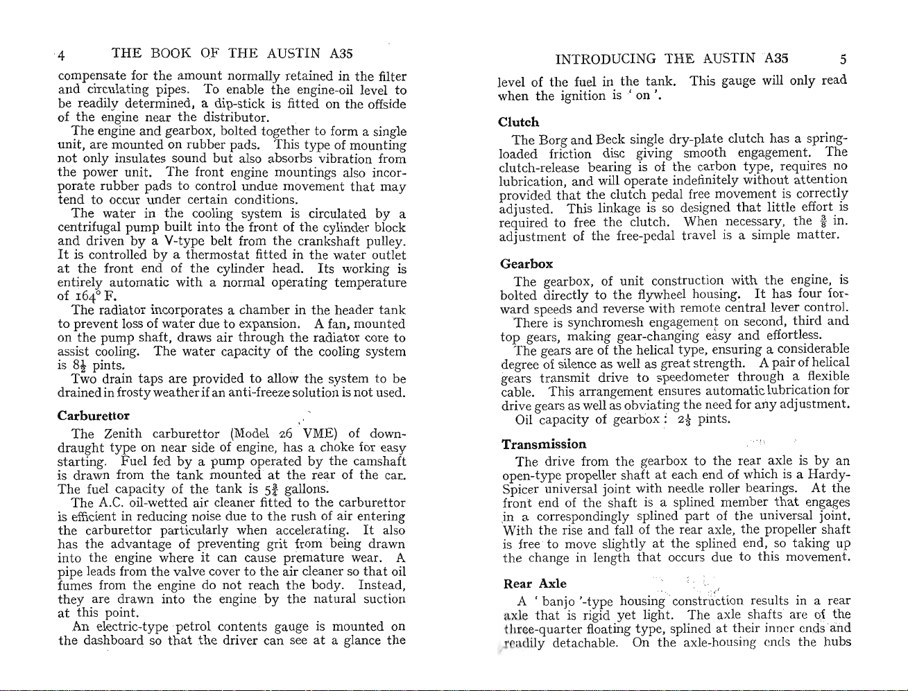
I Choke C
4 Oil Pr essure
7 Air C
II
re
abilit
untilth
can be
wheel
ontr
ol. 2 Dir ecti on Indicator Switch . 3 Headlamp Beam Warning Light .
War
ont
rol. 8 Demister/Defrost cr, 9
Fuel
Gaug
e. 12 Ignition Warn ing Ligh t. 13 Mileage Recorder. 14 Speedometer.
sults
. By carefully p
y to controlthe car on the roadby
e oper
Within
certain limitsthe positions of b
adjust
byopera
side of each seat.
F I G.2.-F
ning Li
ght.
ation
becomes aut omatic.
ed nearer to or f
ting a hand lever an d c
Th
in the desired positions when
The adjustment of
th th
bo
with ease . Make s
nga
e
maymove rearw
to, say, the b
easily leadto f
long j
e clutch and fo
urethatth
ge one ofthe slots inthe ru nners,otherwisethe s
ards
rake
pedal. An un
ati
ourn
eys. .Itwill rew
gue or even to
in selecting the most comfo
with
To deal
left is the clutch
the foot co
peda
forward it disconnects
ully
allowing it to ret
f
ctsthe power ofthe engine tothe gearbox andthence
conne
to
th
Make
clu
tchpeda
e rearax
le, thus causingthe car to move for
an
inflexible rule never to rest
l exc
ept
when necessar y to op
ACIA
PAN
EL
5 Heater Motor Switch. 6 Win dscreen Wiper Switch.
Pan
el Light Switch.10Ignition Switch.
15 Starter Control
ract
ising , you will increase yo
oth
arth
er from the s
atc
h on the
e seatsmay be moved and locked
the
drive
ot-b
thecontro
r's
seat s
rake
pedals can be operated
l is released.
hou
ld be such that
e lockin g device does actually
unexpect edly ifpres
suit
sur
able position
cramp,par
ard
you to spend a few moments
rta
ble adjus
ntro
ls;that
l (4, Fig. 3).
th
e dri ve fromthe engine. Care-
urn
grad
ually withth
tme
atthe ext reme
Wh
en pressed fully
e engine in gear
the
era
day
or ni
front
teer
e is applied
ticula
rly
nt .
ward
foot on
te it.
ur
ght
seats
ing
out
er
eat
may
on
.
the
Some
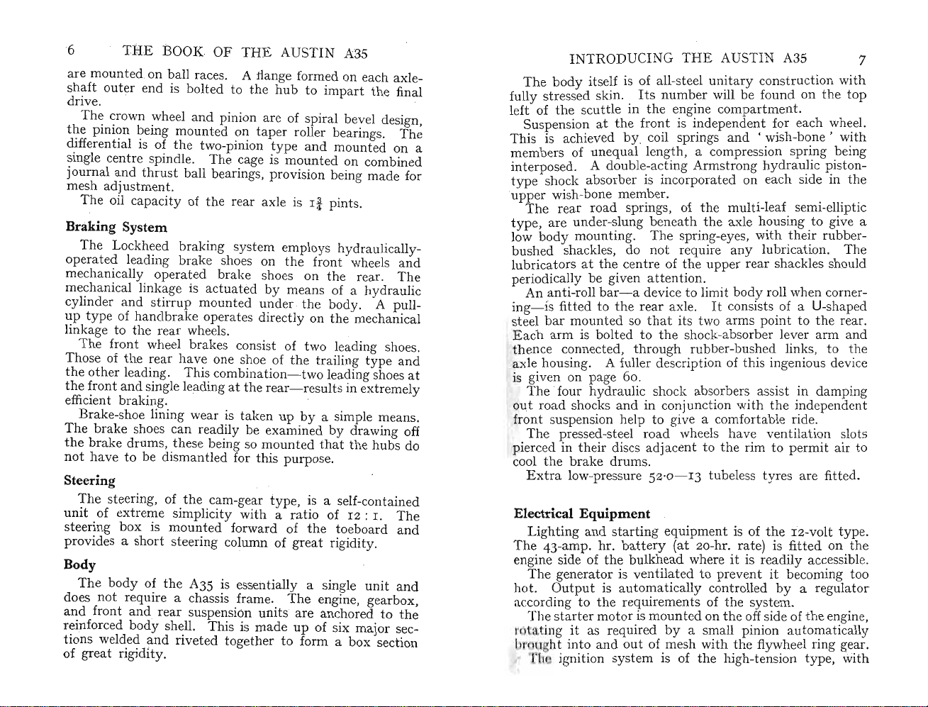
I emistlng Vents. 2 Lighting and Dip Switch. 3 Horn Bu tton. 4 Clutc h Pedal.
5 Brake P eda l. 6 H andbrake. 7 Accelerat or Pedal. 8 Gear Lever
d iv rs t end to use it as a foot-re st , a
r I' it not only causes
11
' assnriIy but can contribute also to cl
)\ l ' essitat an expensive rep
witin yo I annot get
'l'his I ross
The
I cdul in
FIG.3.-DRIVINGC ON TROLS
habit
to be avoided,
theclut
th
th
d.
e centre isthe fo
forward appliesthe hydr aulically o
ch mech
air
job
and
e car home!
ani
sm to wear
utc
h slip. This will
also
embarr
otbr
ake (5, Fig. 3).
un-
assm
perated
ent
I ruk 'S on all four wheels, so bringingthe car to rest.
n th extreme ri
Tid ' I dal is connected by a short cable
I'111'
tt
lIsing 1lie engine speed to increase
or.
l when travelling along
Tit's ar the only controls for which
.t. j
11
onjunct ion w
ghtisth
Pr
essingthe pedal fo
ith
the steering wheel, t
e accelerato r pedal (7, Fig. 3).
andconduittoth
rward
opens
the
thedri
thethrottl
car to move
ver
uses his
hey
are
the
the
road
and
.
n ntr ols.
e
e,
Page 11
12
THE
BOOK OF T
HE
AUSTIN A35
Dashboard Controls and Instruments
Th
e in
strum
ent
panel is well placed and as
th
e la
yout
seen
mentisth
speed of
the
small panel showing
Above
light
th
thatglows red when headli
ahead (3, Fig.
guished by
In
centre p
(II
, Fig. 2) showing
Wh
en filling up with fuel, switch on ignition and gauge will
is essentiallypractical. The
e easily read speedometerthat indi
car. Belowthe 40 mile per hour figure is a
th
e t
otal
mileage covered.
e 20 miles per h
2). When beams are dipped it is
turnin
g li
artition
pet
ourfigur
ght
switch to second position.
e on dial is the warning
ght
beams are directed full
below speedometer isthe petrol gauge
rol levelwhen ignition switch
record rise in tank level as fuel is supplied from
pump
.
th
e left of th e fuel gauge isthe oil-pressure warning
To
ght
light. This li
hed
switc
on and is extinguished when engineis
oil pressure builds-up. Should
running speeds
and a check of the oil level made,
to the engine
(4, Fig. 2) glows green when ignition is
thi
s li
ght
th
e engine should be stopped immediately
may
result. So fool-proof is the oil-pressure
come on at normal
oth
erwise severe damage
will
maininstru-
catesthe
ext
is'
th
e garage
sta
rted and
road
in-
on '.
system, however, that this normally would not occur.
It
is imp
no indic
ati
merely shows th
ortant
to realize
that
this warning li
on ofthe quantity of oil pres
at
pressure is inthe system.
ent
in the sump- it
If
you r
ght
gives
ound
a corner and the oil-pressure lightflickers it may be regarded as a warning
Your daily oil check by
ensure
thatoil is maintained at
Th
e ignition warning li
of fuel gauge. This li
switched on
to indicate
When
indicating
Should
the
light warns
ba
tterymay
when
indication
and
thatcurrent is being drawn from
th
e engine speed is increased the light is extinguished,
that
the
engine st op wi
become
the
engine is runningatits normal speed it is an
that
thatthe sump level is unduly low.
th
e dip-stick (see page 19) shou ld
ght
ght
the
correct level.
(12,
Fi
g. 2) is situated to ri
glows red when ignition is
whenthe engine is stationary or idling,
the
batt
the
generator is charging the
that
thoutitha
ignition remains on
undu
ly discharged.
the
gene
rat
or is
ving been switched off
not
If
charging. Investi-
batt
and
that
th
e lightglows
ght
ery.
ery.
the
be
FOR
THE
BEGI
NNER
gation should be made to establish
not
should
ator
If
pan
el with loud-speaker in pocket to left of speedometer.
Th
be driven for any len
not charging or
the
batt
ery will become discharged.
a radio is fitted it may be placed below
e two controls (6
and
9, Fig. 2) above demi
thefault
gthy
period withthe gener-
are respectively windscreen wiper and panel li
To
start
wipers, switch on control W. To
arm
switch off when
pushthe arms across
Wh
en control is
s areatthe
the
turn
ed 90°the blades start to work
wipers are driven by a motor
th
e bonnet, coupled to a flexible cable r
tran
smits drive to wiper spindles. Mounted at
end oftheir stroke. Do
windscreen.
and
gearbox
ack
. The car
instrument
stercontro
ght
park
mount
ed under
mechanism
bottom
switch.
wipers
not
The
that
windscreen, they are so placed as to clear wide arcs in front
of driver's
passenger's seats. An
int
eresting saf
ety
and
feature incorporated in wiper motor eliminates any possi-
bility of damage to mechanism should wiper blades
as, for example, on ice or packed snow.
autom
atically rest
Switch off when blades are at
att
empt
to pushthem across by hand, or drive mechanism
art
when the obstruction is cleared.
th
eir end oftravel. Do
Themotor
jam-
will
not
may be damaged . Wiper motor can be operated only when
tch
ignition is swi
Pan
el light control (9, Fig. 2)
on concealed lights to illumin
switch
will
Below parcel
th
when
ese accessories are fitted. As
an optional extra.
are
given on page 132.
ed on.
turnsthrou
at
e in
gh 90° to switch
strum
ent
pan
el. This
operate only when sidelights are ' on '.
tra
y is h
eaterand
Inst
ructions for operating
demister control for use
with
radio, heater is
the
controls
Below speedometer is key-operated ignition switch (ro,
2).
Turn
Fig.
clockwise
for'
on'
and
anti-clockwise for
, off,'. As previously explained, switching-on of ignition
into
circuit
the
other
until
driver's
illuminates warning light and also brings
accessories. Ignition key cannot be withdrawn
switch is
tation
s
ary.
'off'.
Do
not
Th
e same key is used
leave ignition ' on ' with engine
to
lock
door.
ter
At each side of speedome
atatthe
Th
starting from cold
left is
the
this
choke control (I, Fig. 2). When
control should remain fully pulled
are two further controls.
13
ls
of
Page 12
THE BOOK
u~til
out
push
for w
It
engine fires,
1D knob so
armi
ng-up.
is good practice to pu sh control home as soon as
possible, otherwise
engine will dilute
a greater
In
rate
than
a corresponding position to choke control,
(15, Fig. 2) is starter-motor control.
until
ignition is switched on. Start
disengages without any action on driver's
OF
THE
AU
STI
N A3S
Dir
ectly engine is running,partly
thata medium-rich mixture is
theundul
th
e oil and
y rich mi
contribu
xtur
e drawn
te to cylinder wear
normal.
but
Thi
s will not operate
er motor engages and
part,
ava
ilable
on ri
otherth
int
ght
an
pulling of cont rol outwards.
Two impor
control should never be op
or when car is in gear.
make a heavy drain on ba
This
can
tant
points to bear in
era
ted when engine is running
Apa
rt from the factthat
ttery
, the car will lurch forw
mind
arethat
thi
s would
thi
ard
be dangerous should anyone be standing in front,
Should engine fail to start or suddenly stop do not again
opera te control
may
be caused tothe ring g
untilithas come to rest, otherwise
ear
on flywheel or to starter-
dam
age
motor pinion drive.
If
engine does not start at first few turns, do not keep
starter in action for a
battery
will be
Instead, find
finding chart on
Combined lighting and dip swit ch is mo
extending to
th
e ri
ny
considerable length of
run
down.
out
what is wrong by referring to fault -
pa
ge 2
18
.
ght
below steering column (2, Fig, 3).
unt
ed on an arm
tim
e or
Turning this clockwise to first notch switches on side and
tail li
ghts;to second, headli
the
thir
d, headli
thelightattop
headli
ghts
when
th
ey are dipp ed.
Thehom
and can be op
Flasher indic
ght
s to full ahead. Aspreviouslyexplained,
of speedom
areatfull-ah
button
(3, Fig. 3) is in centre of
erat
ed when ignition switch is off.
ator
control is
and above speedometer. Move
ing ri
ght
and anti-clockwise for left. A warning li
ght
s in dipped positi
eter
ead
face is illuminated when
position and is extinguished
ste
ering wheel
mount
ed at
it
clockwise to show turn-
centr
on;
a nd
e of panel
ght
incorporated with switch shows when flashers are in
use.
FOR
THE BEGI NN
ER
15
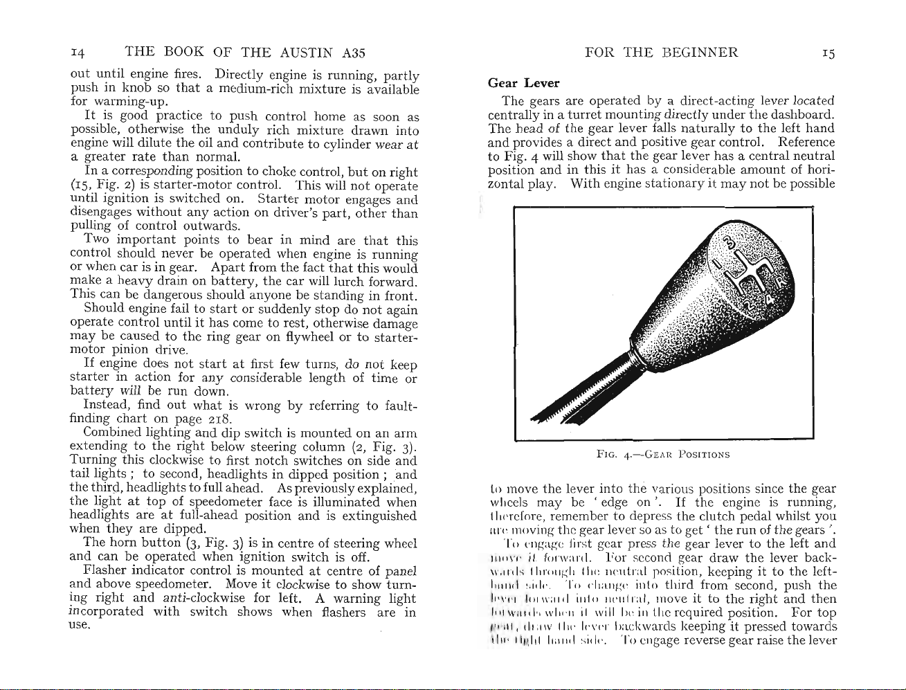
Gear Lever
The gears are operated by a direct-acting lever located
centrally in a
Th
o
at
e head of the gear lever falls n
andprovides a direct and positive gear control. Reference
to Fig. 4 will show
position and in
zontal play.
turretmounti
that
ng directly under
the gear lever has a
thisithas a considerable
With
engine stationary it may
the
atur
ally tothe left h
centr
amount
not
dashboard.
and
al n
eutr
of hori-
be possible
al
s
.
FI
G. 4.
-G
EAR
POSITIO
NS
to move the lever
wheels may be
therefore. remember to depress
ur« moving the gear lever so as to get '
To
ellgage first gear press th e gear lever to
111" \' 1' il forward. For second gear draw
\1',11'1
1"
1111'011/-:
II
l1l1d
~.id(',
h'\,('1 1'
1
lllJ'l
IIII' IIMIII II:IIIII sid." To cngage reverse gear raise the lever
11
11
1\':11.1 iulo nt-ul r.rl, move it to
1Will .1'1 WIIl'II il will Iw ill the required position. For
l,
dllll
V II I., 1.,\,(,
11111
'1'" ('
int
o th e various positions since th e gear
'ed
ge on '.
If
th
e engine is
th
e clutch pedal whilst you
therunofth
th
e left and
th
e lever back-
(: ne
utr
al position, keepingitto the left-
lia
ng(: into third from second, push
th
e right
1'
backwards keeping it pressed towards
runn
ing,
e gears '.
the
and
then
top
Page 13
16
by pullingitupw
fully tothe ri
spn ng pressure
adjac
lever being pulled up and rearw
tothe rear wheels. A
position by.a
the
Sometimes, and particularly if the
with
r
ear
or by
clearing with the
to apply
brak
on.
gr
this m
in cases where
brake cannot readily be released,
brake p
the
THE
BOOK
ght
prev
The h
andbrake
ent
to his ri
tr.igger and a pawl.
pa
wl IS disengaged
some force,itis necess
wheel
brak
es either by pressing
wingthe h
th
e h
andbrak
Ther
dra
e are two
e pedalatth
The
leverage obtained on
eat
er t hanthat
eth
od ofapplication may befound helpful p
the
OF
THE
AUS
ard
s againstthe spring pressure, move
andthen rearw
ent
s its being engaged accide
lever is to
ght
hand.
ratch
andthe
ard
s. The resi
therightofth
lt
is of the pull-on type, the
ard
s to apply
et locksthe lever in
By
squeezing this trigger
handbr
br
ake has been applied
arytotakethe weight offthe
the
and
brak
tri
gger.
tip
s you may like to know.
e slightly h
e verysecurely, press downthe foot-
e same
tim
e pulling
the
developed by the
car is left on a g
thehand
foot-brake is
han
radient.
pr
edal;
thi
s will be found of assistance in releasing
pawl.
Th
e doors ofthe A35, either the two- or four-door
may be opened from either inside or
senger doors can be locked from
inside handles
upw
ards
beyond.
driver's door is locked from
key. When
raised, no doors
automatically
are raised. Remember to
to pre
vent
inside door
lt
is useful to make a
ignition key so
thus
locked,
can
the
sliding front door windows, whenthey
and
be opened. This position also locks
shut
anyone from insertinga stickto release one of
handlesand
so gain entrance to
noteofthe
that
you
may
ment without delay should
key can be obtained
The luggage
the
ignition
car
when necessary.
compartment
key
at
any
enabling you to leave your luggage in the
the
insidebyraisingthe
the
the
normal position.
outside
with
handles of other doors
all the windows suffici
be able to
the
need arise. A duplicate
time
through
boot
has
TIN
A3S
it
stan
ce by
nta
the
the
lly.
seat
brake
' on '
e driver's
ake is released.
foot-brake pedal
ard
er on and
If
then
you want
brake lever
rath
er
dbrak
e lever
If
arti
th
e hand-
and
cularlv
ess downthe foot-
mod
out
side.
Th
el,
e pas-
Th
withthe ign
ition
ently
the
the
car
.
code number of the
obtain
a replace-
your dealer .
a lock
that
accepts
capable
the
~un.
reta
17
the
in
FOR
THE
Th
ere are se
venient
roof above
and
helpful.
the
veralbod
y fittings
Forinstan
windscreen on
of being readily hin ged down,
lt
can
also be moved sideways within limits and ISspnng-
loaded to provide
it
in
the
desired position.
th
e necessary degree of friction to
BEGI
NNER
tha
t
will
ce, a visor fitted to
the
driver's side,
redu
ces glare from.
be found con-
and
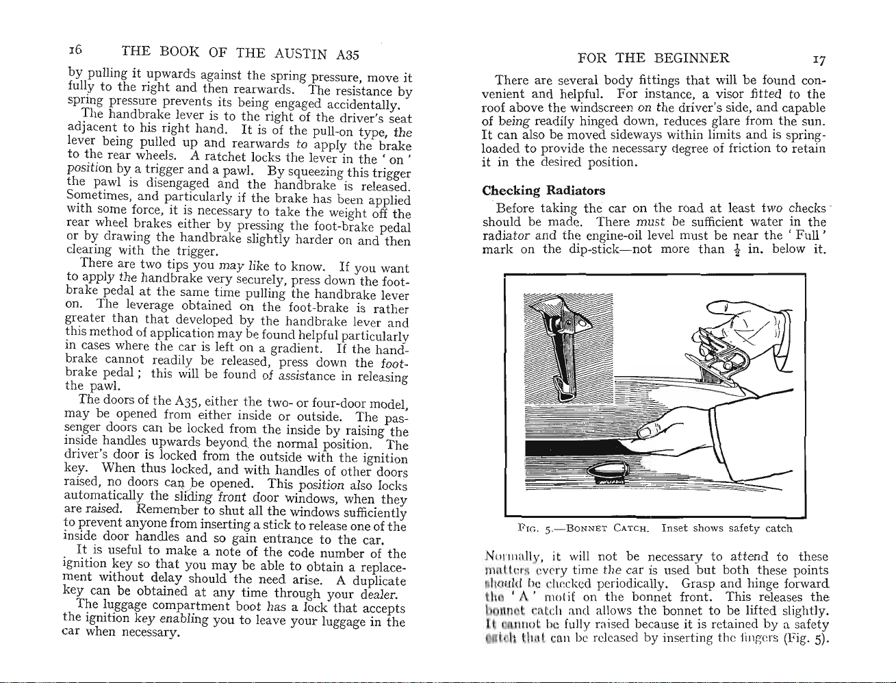
Checking Radiators
Before taking
should be made.
radi
ator
mark
and
on
the
the
car
on the r
Theremu
the
engine-oil levelmust be
dip-sti
ck-not
st be suffic
more
oadatleast two checks -
ient
wat
er in
the
n
e~r
the
'
than
t m, below It.
Fu~
,
e
Fro
. 5.
-BoNNET
1'
111
11
. ' I' 'v ry t ime th e car is used
it will not be necessary to attend to
til l b h k d periodically. Grasp
mot
, .
if nthe bonnet front. This releases
CATCH. I n setsh
owssafetycatch
butboth
.these points
and
hinge forward
the
se
the
l It an 1 allowsthe bonnet to be lifted slightly.
I t b fully raised because it .is reta
in
ed by a
~afet
y
'h n b r leased by inserting the fing rs (FIg. 5)·
Page 14
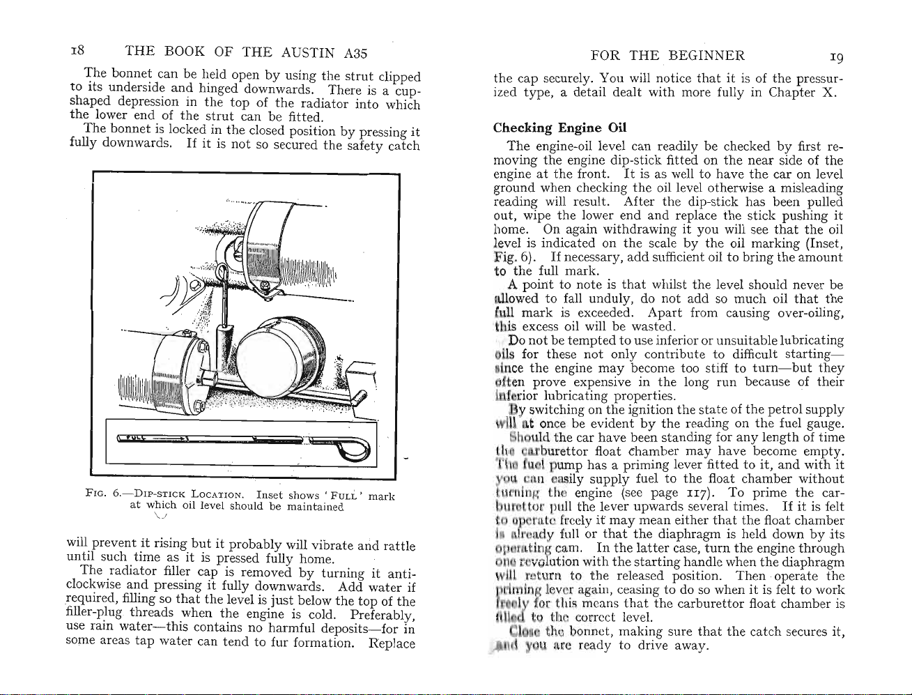
18
to its
shapeddepr
th
e lower end ofthe strut can be fitted.
fully down
will prev
until such
The r
clockwise
required, filling so that
filler-plug
use rain
some areas
THE
BOOK
Thebonnet
under
can be held open by using
side
and
ession inthe
The
bonnet is locked in the closed position by pressing
ward
s.
F IG.
6.-
D I P-STI CK L OCATI ON . Inset shows ' F U LL ' ma
atwhich oil level should be mainta
\J
ent
it rising
time
as it is pressed fully hom e.
adiator
water-
filler cap is removed
and
pressing it fully downwards. Add wat er if
thr
eads when
this contains no harmful deposits
tap
water
OF
THEAUSTIN
hinged downw
topoftheradiator
If
it is not so secured
but
it probably will vibrate
the
level is
the
just
engine is cold. Preferably,
can tend to fur formation. Replace
A35
the
stru
ard
s. There is a cup-
t clipped
into
the
safety catch
ined
and
by
turning it
belowthe
topofth
-for
which
rk
rat
tle
ant
in
FOR
THE
BEGIN
the cap securely. You will notice
ized type, a detail de
Chec
it
kingEngine
The
moving
engine-oil level can readily be checked by first re-
th
engineatth
e engine dip-stick fitted onthe near SIde of
e front.
ground when checking
reading will result. Aft er
out , wipethe lower end
alt
with
Oil
It
is as well to havethe
th
e oil level otherwise a misleading
th
and
home. On again withdrawing
vel is indicated onthe scale by
ig.6).
o
A po
owed to fall u
11
is excess oil will be
Do
If
necessary, add suffici
the
full mark.
inttonot
e is
nduly
that
whilstthe level should never be
, do
not
mark is exceeded. Apartfrom causing over-oiling,
wast
not
be t
empt
ed to use inferior or un
notonly
may
ce
for
the
th
ese
engine
n prove expensive in
ed.
contribute to diffic
become too stiff to
the
NER
thatit is of the pressur-
more fully in Chapter X.
the
car
on level
e dip-stick ha.s been I?ull
replacethe stick pushing l.t
it
you will see
the
ent
oil marking (
oil to bringthe
addsomuch
suitabl
long
run
that
the
Ins
amount
oil
that
the
elubricating
ult
star
ting-
turn-bu
t they
because of their
e.d
011
et,
ior lubricating properties.
switching on
once be evident
uld
th
ure
ump has a priming lever fitt ed to
n ily supply fuel to
ng h engine (see page
t 1ull the lever upwards several
t Ir ly
y full or
opl:)rn.tingcam.
u
i-
t
e
1l'II11
i n with
urn to
lng1 v r again, ceasing to do so when
r
thi:
th
e ignitionthe state ofthe petrol supply
by
the
reading onthe fuel gauge .
e car have been standing for any length of time
tt
or floatchamber may have become
it,
the
float chamber without
II
7). To primethe cartim
es.
and
If
empt
with
it
is fe
itmay mean eitherthatthe floatchamb er
that
thediaphra
Inthe
latt
th
th
e released position.
ma
ns thatthecarbur
er case,
e starting
gm is held down byits
turnthe engine
handl
e whenthe dia
Th
en operatethe
it
ettor
is felt to work
floatchamber is
throu
phra
gh
gm
y.
it
lt
th rre t level.
th bonnet , making sure that
th
e catch secures it,
ready to drive away .
Page 15
20
BOOK OF
THE
AUSTI N A3S
THE
Starting the Engine
After
tak
on, i.e. pulled up,
on-thatis,
positi
thr
ough its ce
hav
e been caused by failure to take this routme precaution,
When s
we
ath
han
ta
er, it is helpful to
dle a few times before switching on. This relieves its
andthatthe gear lever is in
whe.r~
ntral
it can ?e.
position. Thi s
rting from cold, particularly during fros
turnthe engine by the starting
initial stiffness and greatly reduces
ta
ing your seat see thatth
rter motor and- much
s
It
is also good practice to press downthe clutch pedal for
this again reduces
mor
e important- onthe ba
th
e load and eliminates the drag of
e handbrake lever is
the
e.asil
y moved
IS
I~port
the
load both onthe
sid~ways
~ntasaccId~
neutral
nts
tte
ry.
the
oil on the gear wheels. .
If
th
is held frictionally in any i
Pull
to run.
If
control
bothsta
resisting the temptation to .keep It m use l?nger. t
necessary under
up more quickly if this is done. It is b
drive away slowly since
allowingthe choke to befully released
e engine is cold. pull outthe choke control. This
nt
th
e starter knob
Dir
the engine
until
andthe engine should soon commence
ectly it does so, release the starter control.
'cu
ts out ' and stops do not again usethe
the engine is at rest otherwisethe drive of
ermediate position ifturned.
rter and flywheel may be damaged. .
When
th
e engine is
run
ning,
th
e impression t
th
g
ra~u~lly
hat
releasethe
the
engme will warm
ett
er practice to
e engine will then w
s?o
n~r.~yadoptI~g
chok~,
han
arm
"?-p,
this procedure not only willthe lubricatingOJI reta.m ItS
properties longer, because it will not tend to become dil
by excess petrol, but p
etr
ol will
not
be wasted.
ut
Starting When Warm
Once
the
engine is warmed up it is
ary
to usethe choke
s
and
, of course,the accelerator
be left inthe normal idling position.
the
so opening
throttle,
not
only will
not
normally neces-
If
it ispressed down,
the
idling
must
jet
rendered inoperative- since it relies for its action on the
suction set
accelerating
cause difficult
up
pump
star
bythe
may
ting should
virtu
inject
ally closed
petro~
into
the
mixtur
throttle-but
the
manifold ?-nd
e become too
th
nch.
ty
ed
be
IS
FOR
THE
BEGINNER
This
matter
Carburettor (Chapter
If
the
advisable t o use
having
circuited with petrol
happ
ens, push in
pr
essing down
theunduly
engine commences to fire, gradually
it is felt to pick
If
the
cleaning. The simplest me
thathave
choking ' the engine is to place them on
th
eir'business
and
allow the petrol to
useful accessory a
oth
erwise wipe away the soot with a rag. Before replacmg
th
em in the engine
points is not bridged with carbon or flu
Th
e golden rule is to use
is covered more fully when we deal with
VIII).
engine has cooled down a little it may be found
th
themixtur
the
rich mi
e choke momentarily.
e too rich for thenthel?lugsmay be
and
no sp
the
choke control fullyatthe
ark
accelerator so that asthe engme
xtur
e will be cleared. As soon as
up
speed and agam
will occur.
:ele
ase
run
If
so, beware of
s~me
the
choke when
normally.
engine still refuses to start ren::ovethe plugs for
th
become w
-ends'
ett
ed with petrol as
together, apply a li
od oftre
burn
'fi
make
le-car
off.
d',
surethat
the
atmg
spa
rkmg plugs
result of ' over-
th~
ground with
ght
ed m
have
that
up w
gap between
ff.
fron::the.rag.
brush
If
the
you
them
the
choke WIth discretion,
shor~
If
time
turns
atch
most
ith
th!s ;
2I
the
~hIS
the
the
Driving Hints
Before you can take
o
bta
in a provisional driving licence so
ta
ught to drivebyan experienced friend orbyone of
many
motoring schools in
theoffi
by
cial driving test you must always be accompamed
a driver who holds a current driving licence.
desirable to take
among
repu
be
move
it
e
that
If
your
tati
set
To st
the
fully towards
the
this
acquaintances or
on. Eve n so,the following instructions
down and borne in mind :
art
from rest, first press down
gear lever to
the
lever will
occurs,
return
clutch, declutch
the
car on to
the
road you
that
stru
ctors. U
your
lessons with some co
the
bottom-gear positionbypressing
at
ntil
you have
a school
the
clutch pedal
mpet
left andthen forwards. You
not
readily enter
the
bottom
it to neutral , momentarily engage
and
again move
the
gear lever to
you
may
be
the
must
pa
s~ed
It
is most
ent driver
with
a good
may
well
and
may
find
-gear position.
the
the
bottom-gear position when it should fully engage. This
Page 16
THE
22
BOOK OF
difficulty sometimes arises duetothe
eth
are
gear te
mesh. Allowing
alt
ers
their
'edge
the
rel
ati
ve positions
THE
AUSTIN A3S
fact
that
the
sliding
on'
to each
other
and
thus
cannot
clutch pedal to engage momentarily
and
so permits
them
engage.
Now release
thehandbr
wards slightly to ease
free
the
rat
chet
and
If
it is difficult to release
th
e foot-brake pedal to relievethe tension on
on
brak
e linkage. .
Pr
ess downthe accelerator slightly atthe same time
th
allowing
e clut ch pedal to come gently up
move forward as
not
e isthatthe simultaneous actuation-one up
-ofthe clutch and acceler
down
and
possibly uneven clutch engagement may ensue. Per-
push
the
severe, however, for it is only
mind
Bear in
clutch engagement
harmful for
thatthe hall-mark of a good driver is smooth
andthat
it
causes severe mechanical stress.
ake lever, first pullingitup-
the
pressure, squeeze
the
lever forwards
the
holding
the
and
rat
downwards .
chet,press firmly
and
clutch engages. The first
ator
pedals is
masteredby
harsh clut ch engagement is
trigger to
the
hand-
the
car will
point
and
one
not
easy
experience.
Gear Changing
When
th
e car is moving forward steadily it will be neces-
th
ght
e main bug-
th
e accelerator
tim
e pushing '
without
resistance
Whenthe
the
gears will
may
sary to change into second gear. One of
bears of
eliminated by
th
e novice-gear changing- is almost entirely
th
e synchromesh device.
To change from first to second gear, allow
return
to
down the clutch pedal as far as
unduehast
a ste
be felt
synchromesh device has come
to its closed position atthe same
it
ady
pre
but
e, move
ssure on
maintain
the
gear lever rearwards maintaining '
the
lever. A sli
the
pressure onthe knob.
into
will go. Then,
action
mesh and second gear will be engaged noiselessly. Allow
the
clutch pedaltoreturn
the
down
accelerator when
gently. At
the
car
will move forward
the
same time press
with
increased speed.
third
To change from second to
accelerator and depressthe clutch pedal. Move
lever deliberately forward into
similarly release
the
neutral position main-
the
gear
to
to
the
FOR
THE
taining a pressure to
forward into
and
control the speed ofthe car by
The
acceler
th
e gear lever rearwards
pr
essure on
a
Practi
third
final change
at
or pedal, depressingthe clutch pedal,
se gear changing in
the
speed. Allowthe clutch pedal to return
intotop
into
the
lever towardsthe right-hand side.
BEGIN NER
right throughthe
the
gate
accelerator pedal.
gear is effected by releasing the
and
top-gear position, maintaining
thismanneruntil
the
car moves
23
andthen
moving
forward smoothly and steadily after each gear change.
Carefully synchronize pedal movement to ensure smooth
ta
engagement in all circums
To Change
It
is equally necessary to learn how to change down
Down
to a Lower Gear
from a higher to a lower gear. This is essen
climbing a hill that normallythe car could
top
gear or whichever other gear may be in useatthe
tim
e. Also,
more slowly
In
changing down from top to third gear and from
to second adop t
pressure on
th
push
tra
ffic conditions may necess
th
an normally is permitted by top or
th
th
e gear lever
e following procedure. Maintainthe
e accelera
stea
nces.
tia
l
ascend
third
wh
gear.
not
ita
te travelling
thi
tor
and de-clutch. Simu
lta
neously,
dily into the desired position. The
synchromesh device again comes into action to give a silent
change. Release
th
e clutch pedal, controllingthe speed of
the car by using the accelerator pedal as necessary.
ent
A slightly differ
changing down from second to bo
is no synchromesh device. An easy change can be
however, by adopting
de-clutching '. Although this procedure
be complicated it is simple and you should
procedure should be adopted when
tt
om as in
thi
s casethere
mad
th
e technique known as ' double
may
appear to
pra
ctise until
you are proficient.
Pr
oceed as follow
(a) De-clutch. Move
th
e pressure on
(b)
Allow clutch to engage, with gear lever in neutral,
and
(c) Release
accel
move gear lever
s:
th
e gear lever
the
accelerat or.
eratethe
pre
ssure on accelerator pedal, de-clutch and
engine.
int
o first-gear positionatonce.
int
o n
eutr
al, releasing
~n
III
rd
e,
Page 17
THE
BOOK
(d)
Engage clutch, operate accelerator tomaintain
~
~.
Practisethis drill
cer
tai
n an d
pa
rticularly when ascending hills on which b
couldhave been used.
Tostop
cel
erator
Justbefore
dut
ch.
gear
intoneutral
rapi
the
car, firstof all take your foot offthe ac-
and
moveitover tothe fo
the
Wh
en s
OF
THE
AUSTIN A3S
desired
until
you can be sure of
d gear change in any circumstances,
ot-
brake t o
vehicle comes to a standstill depressthe
topp
ed applythehan
andthen release
the
clutch and fo
dbra
ott
ke,
makin
g a
om gear
the
left.
movethe
otb
rake,
Reversing
When
stationary.
is moving forwards will cause severe strain or
the
With'the
'd utch
will rise no further.
theright
intothe reverse position.
it forw
r
eturn
andagain
and gen
Almost
the steering is now reversed.
steering wheel tothe ri
temporarily the r
become familiar
l
earn
:practise re versing betweenthem- for instance, asifback -
In
novi so
pia.
mudguard and
carthat is ah ad of you. A li
show you how much room
engaging reverse gear the car
Any
attempt
transmi
It
into a line of parked vehicles. Nothing indicates
ssion
syst
car
station
and
lift
the
maintainingthe lift. Ne
ards
momentarily allowing the clutch p
as when engaging firstgear. De-clutch once more
movethe leverback
tly
acceleratewhenthe car will move backwards.
the
firstthing you will realize, of course, is
ear-t
withthese cha
how to
is a helpful idea to erect two guide marks
bac
k your carne
much
as inabi
not forget to allow for
bump
to go
int
em.
ary
and
the
gear lever
Th
ght
o move tothe left .
er w
upw
en move it
If
it
does not engage fully, move
wards.Engageth
Thatis to say,turningthe
causesthe front of
nged
atlyintoth
lity
to back his
hen
pulling
ttl
e practice
you
may
o reverse whenthe car
conditions,however,
mu
st always be
dama
engine
ardsuntilyou
through
xt,
the
runn
the
pullitrearwards
You
e desired
swing of
out
car
from
posit
and
neatly
will
allow.
the
v
ge to
ing, de-
feel it
gate
edal
e clutch
that
car-
will
soon
and
ion.
then
into
the
front
behind
ery
soon
the
to
to
to
.
a
FOR
THE
BEGINNER
Skidding
The
brak
efficient
except, of course, in emergency.
tyre
life as well as straining
Ev
•
never
of some
whenthe
unpleasant feeling
control.
first !
immediately releasethe
them
this factor is
What
sideways towards
roa
d. Often
the
steering wheel in
the skid develops.
direction you
Do
may
control inanisol
bus
drivers
to t eachthem
Tr
y to bearin
(I)
(2) Do
(3) Do not
(4) Do
es on
butitis
ery
novice fears a skid. Whilstit is easy to
provoke a
otherper
sur
It
If
you
avoiding
generally
not
forget
be of gr
and
Ste
er a steady course . Ne
not
harshly.
if your
not
falls so
to
vibrate
Running-in a Reconditio
When
become
the
beyond
your
Au
bad
dri
skid'
son's
face is wet.
that
slides forward
have
timetomake
any
tendency
the
cause of a skid.
happensisthat
the
the
skid
If
may
finish up acrossthe
that
eat
accele
driv
road
that
knowing what to do in an emergency
value.
ated
dri
vers of police cars use a ' greas
the
correct technique.
mind
rate
e onthe crown of
speed is low. Keep well to
allowthe engine to labour.
the
unduly
stin
ving tec
thecargenera
you
may
stupidity,tojam
Then
the
carisnotentire
and
brakes.Then
to lockthe wheels. Often
gutter
will become co
the
pla
engine
or tothe lower side of the
same direction as
you
turnthe wheel in
If
you are able to
ce you
the
following four p
nor
apply
runs
, change down to a lower gear.
ned
engine has done consid
furthe
r r
epair-inthat
A35
are
hniqu
e to use them harshly
Har
be compelled, because
youmay experience the
not
a split-second decision,
the rearwheels swing
ntr
will
realizethe reason why
ver
the
the
heavily, pinks, or appears
Eng
ine
era
powerful
sh braking reduces
lly.
on your
ly under
necessarilyradiator
carefully re-apply
ollable if you
that
road!
swerve abrup
brakessudd
road,
ble serviceitmay
case a reconditioned
brakes
to which
the
pract
ise skid
e-patch'
oints:
tly
enly or
particularly
the
If
the
25
and
say
your
turn
other
.
left.
speed
Page 18
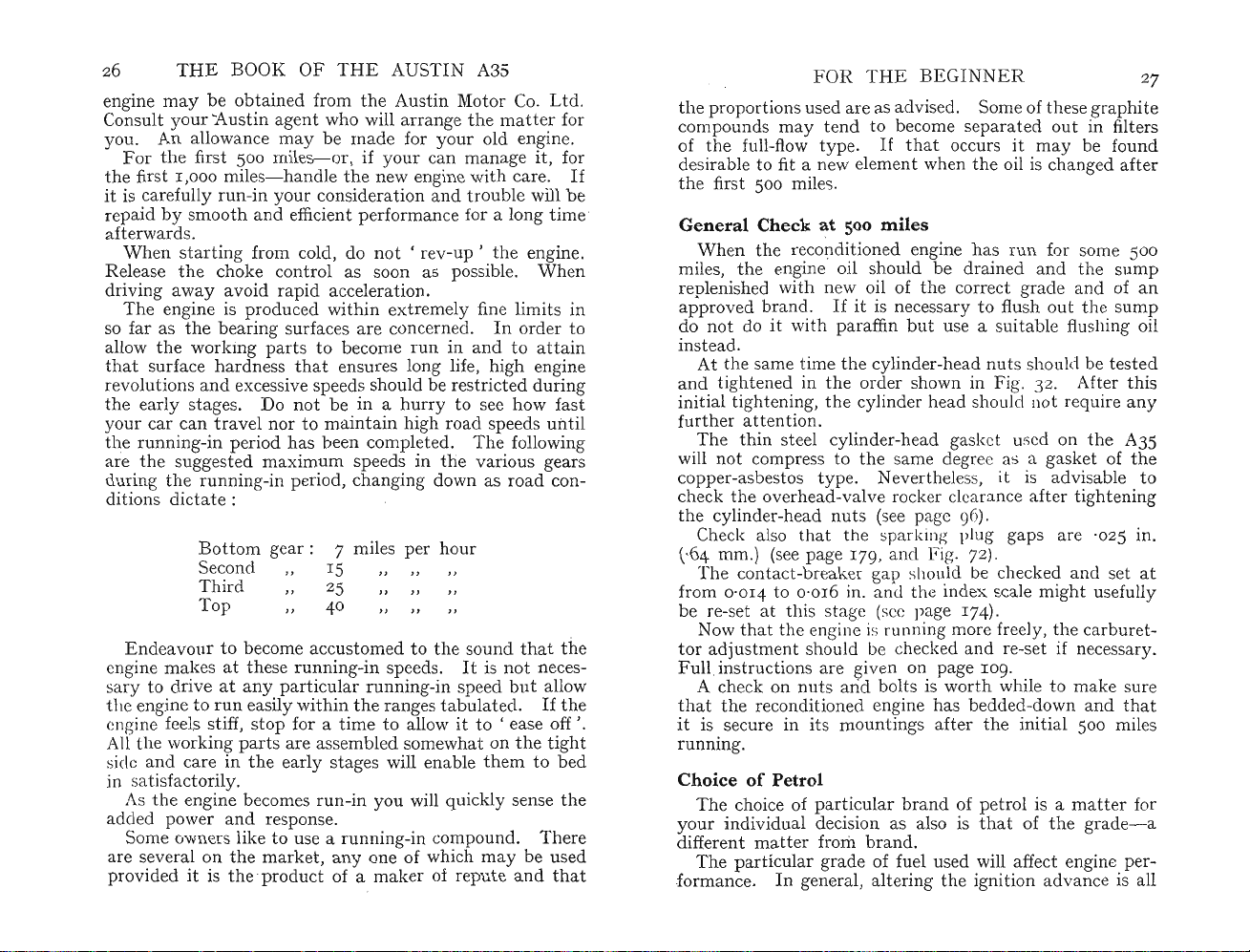
26 T
engine may be
Consultyour'Austin agent who will a
HE
BOOK
obt
OF
THE
AUSTIN
ained fromthe Austin M
rra
A3S
otor
ngethe
Co.Ltd.
matt
er for
you. An allowance may be made for yourold engine.
Forthe first500 miles-or, if your can manage it , for
th
e first1,000 miles- handlethe new engine with care.
it is carefully run-in
repaid by smooth and efficient performance for a long
your
consideration and trouble will be
tim
afterwards.
Wh
en starting from cold, do not're
Releasethe choke co
ntr
ol as soon as possible.
driving away avoid rapid accele
The
engine is produced
withinext
rat
v-up'th
e engine.
Wh
ion.
remely fine limits in
en
so far asthe bearing surfaces are concerned. In order to
allow the working parts to become
that surface
hardn
essthat
ensures long life, high engine
run
in and to a
tta
revolutions and excessive speeds should be restricted during
th
e ea
rly
your car can
th
e ru nnin g-in period has been completed.
arethe suggested max
duringthe
trav
el nor to ma
imum
runnin
g-in period, changing down as road con-
stages. Do not be in a
hurr
intain
y to see how fa
high
road
speeds until
The
following
speeds inthe various gears
ditions dictate:
Bottomgear:
Second
Third
Top
End
eavour
engine
to become acc
makesatthese
sary to driveatanyparti
the engine to
run
easily withinthe
7 miles per h
15
25
0
4
usto
runnin
g-in speeds.
cular
our
med tothe soundthat
It
is
runnin
ran
g-in speed
ges t
abulat
not
but
ed.
the
neces-
allow
If
th
engine feels stiff, stop for a time to allow it to ' ease off '.
All the working p
side and care in the ea
art
s are assembled somewhat onthe tight
rly
stages will enablethem to bed
in satisfactorily.
/ I.S th e engine becomes
run
-in you will quickly sense
the
added power and response.
Some owners like to use a running-in compound.
are several on
provided it is
the
mar
theprodu
ket, any one of which may be used
ct of a mak er of r
eputeand
Th
ere
that
FOR TH E
the
proportions used are as advised. Some of th ese graphite
BEGINNER
27
compo unds may tend to become separa ted out in filter s
ofthe full-flow type.
If
e
desirable to fit a new element whenthe oil is changed
the first 500 miles.
General Check at
Whenth
e reconditioned engine has
miles, the engine oil shouldbe drai
replenished
approved br
do not do it
in
inst ead.
with
and
with
.
At the same timethe cylinder-headnuts should be te
and tigh
st
initial tightening, th e cylinder head should not require
further
will
copper-asbestos
tenedintheord
attention.
Thethi
n steel cylinder-head gasket used onthe A35
not
compress to
typ
check the overhead-valve rocker clearance afte r ti
the cylinder-head
If
thatoc
50
0
miles
new oil ofthe co
If
it is necessary to flush
paraffin
but
use a suit able flushing oil
er shown in Fig. 32. After this
the
same degree as a gasket of
e. Nev
nut
erth
eless, it is advisable to
s (see page 96).
cursit
run
ned
rrect
may be found
for some 500
and
the sump
grad
e and of an
outthe sump
ght
aft
ste
any
the
ening
er
d
Check also that the sparking plug gaps are '025 in.
(,64 mm.) (see page 179, and Fig. 72).
The contact-breaker gap should be checked and set at
from 0'014 to 0'016 in. and t he ind ex scale mi
be re-set at
thi
s stage (see page 174).
Now thatthe engine is running more freely,the carb
tor
adju
Fullin
stm ent should be checked
stru
ctions are given on page 109.
and
re-set if necessary.
A check on nuts arid bolts is worth while to
e
thatth
it
runnin
Cho
e reconditioned engine has bedded-down
is secure in its mountings
g.
ice
of Petrol
Th
e choice of p
arti
cularbr
aft
er the init ial 500 miles
and
of petrol is a m
your individual decision as also isthatofth
differentm
The
formance.
att
er from
parti
cular grade of fuel used will affect engine per-
In
general, a
brand
lte
.
ring
the
ignition
ght
mak
e gra
adv
ance is all
usefully
uret
e sure
andthat
att
er for
de-a
-
Page 19
28 THE BOOK OF
that
is required to obtain
different grades of fuel available.
fuels, however, full advantage
increasingthe compression ratio, a procedure
generally
tributionofth
road testing
setting, is described on page 177.
At
ally available. These are
Regular is somewhat similar to war-time
Premium corresponds roughly to No. I petrol available
before
Premium
perties giving improved performance.
the
the
worth
whileatpresent due to
is special grade of petrol.
the
car
time
of writing, there are two main grades gener-
War.
grad
es contain some
In addition, in determining which grade to use,
must
also be
pression
increased
one originally fitted.
Whenitcleared
was
adjusted
ignition setting, Premium fuel may
benefit. This advantage
ignition is
ignition
Conversely, an engine
Premium
Regular grade is used. Again,the-ignition should be adjusted to
taken
ratio,and
by
settosuit
must
fuel will
suit
into considerationthe m
whether
the
introduction of a different gasketto
the
to accept Regular fuel.
be advanced (see page 177).
not
it. '
THE
AUSTIN A3S
the
maximum
can
to obtain
Works,
this grade of petrol. Usu ally
with
the
'Regular'
additivesthat
this
ration
your
may
be obtained only if
ignition
give a good performance if
benefits from
For
the
only be
most efficient ignition
reconditioned engine
timed
higher octane
obtained
thatisnot
the
limited dis-
The
method
and
' Premium'.
confer pro-
atter
has been lowered or
With
this
not
give
the
to operate
the
by
'Pool'.
there
of com-
the
original
fullest
the
the
with
the
of
CHAPTER
III
GENERAL MAINTENANCE
Body,
Wheels
HOSE MOTORISTS who are of the opinion thata
chassis is a metal frame the
T
supportthe
chassis
th
e wheels, axles, springs, steering connect ions, tyres, etc.
These components do
but
tion
pr
operly lubricated will do much to remove the squeaks
and
rattlesthat
the world
Keeping
Manufacturers today use torque spanners to enable a
definite degree of
rubb
er gaskets are used in m
to control tightness of nu ts securing
tension is achieved
individual assessm
It
is advisable to periodically examine all
ness.
rattles, squeaks andaccelerated wear will result. Some
bolts are secured by tab washers, some
there
remove
and
re-tighten. Do
have
pins
and
from becoming loose.
A
cotter
or
stud
so positioned
making it impossible to withdraw
any
slackening of
body
may
wonder
can
require. Actually,the term chassis embraces
not
care in keeping
are
not
the
owner's neglect.
Nuts
and
Bolts Tight
tightn
by
ent
s of wh
If
neglected they will become
is evidencethat such bolts are
the
pin or
been
tight
tab-washers
pin passed through a hole in
passes through
bend
not
ened. Cotter (or sometimes called split)
are
the
the
ends of
the
nut
and
Tyres
pur
pose of which is to
whatmaint
require a great amount of a
nuts
and bolts tightand all
only annoying but advertise to
ess to be obtained. As cork or
anyparts
pre-set loadings
at'
seems to be
not
back
the
29
split
tab
pin
the
forget to secure
two means ofpreventing
slots in a castellated
the
itself.
enance such a
it is
very
desirable
th
ese parts. Correct
rather
rapidly
by
correctly tightened
washer as required
them
the
are
pin
tight
nuts
cotter
end
nut
bent
and
than
enough '.
for tight-
looser
pins.
when
of a
. When
back
preventing
tte
part
and
they
nuts
nut
thus
n-
s
by
If
Page 20
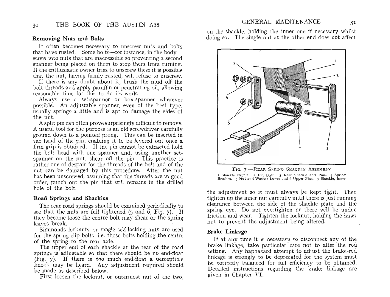
30 T
Removing
It
thathav
screw
spanner bein!5placed on
If
theenthu
thatth
If
bolt
reasonable time for
Always use a setpossible. An
usually springs a little an d is apt to
HE
BOOK OF T
HE
AUSTIN
Nuts and Bolts
often becomes necess
e rusted. Some bolts
into
nut
s thatare inaccessible so preventing a second
ary
to unscrew nuts
-forinsta
t~
em
to s
top
nce, in
them f
siastic ownertnes to unscrewthese it is possible
e nut,
hav
ing firmly rusted, will refuse to unscrew.
there is any doubtabout it,
thread
s and apply
adju
par
affin or pen
thi
s to do its work.
spann
stable
er or box-sp
spa
brushth
etr
ati
ann
nner, even ofthe best t ype,
dam
agethe sides of
A3S
and
the
bod
rom
turnin
e mud off the
ng oil, allowing
er wherever
thenut.
A split pin can often
A useful tool for th e
ground down to a pomted
the h
ead
firm grip is
the
spanner on
rath
nut
of th e pin, enabling it to be levered
obtain
bolt
head
the
er one of despair forthe
can
be
dam
has been unscrewed, assuming
order,
punchoutthe pinthat
hole of
the
bolt.
prov
e surprisingly difficult to remove.
~urpose
ed.
with
one spanner and, using
nut
, s
is an old screwdriver carefully
pron
g. This can be ins
If
th
e pin cannot be extracted hold
another set-
hea
r off th e pin.
thr
eads ofthe
Thispractic
bolt
ert
out
once a
andofth
aged by this procedure. After the nut
thatthe
thr
ead
s are in good
stiJl remains inthe drilled
Road Springs and Shackles
The
rear road springs should be examined periodically to
see
thatthe
they become loose the centre boltmay
nuts
are full ti
ght
ened (5
and6,Fi
g. 7).
shear or the spring
leavesbreak. .
Simmonds lo
forthe spring-clip bolts, i.e.those bolts holding
of
the
spring tothe rear axle.
The
upper
prings is adj ustable sothat
(Fig. 7).
knock
may
cknut
s or single self-locking
end of each shackle at the
there should be no end-float
If
the
re is t oo much end-float a
be heard.
Any
adju
stm
nuts
rea
r of the road
ent
required should
are
thecentre
per
ceptible
bemade as described below.
Firs
t loosenthe lo
cknut
, or o
uterm
ost
nutofthe
bolts
y-
ed in
e is
used
two,
g.
GENE
RAL MA
onthe shackle, holding
doing so.
e
the adju
The
single nutatthe
FI
I Shackle Nipple. 2 Pin Bush. 3 Rea r Shackle and
Brushes . 5 Nut
G. 7.-RE AR S P
and
Washer Lower and 6 Upper P ins. 7 S
stm
ent so it must always be
tighten up th e inn er nutcarefully
clearance between the side ofthe shackle
sprin
If
g eye. Do not overti
friction
nut
and
wear. Ti
to prevent
the
ght
adjustment being
INTENANCE
the
inner one if neces
oth
er end does
RINGSHACKLEASSEM
Pins
kept
untilth
ere is just running
plat
ght
en or there will be
en the locknut, holding
alte
red.
sar
not
BLY
. 4 Spring
hackl
e, Inner
tight.
e and
the
y whil
affect
Then
undu
inner
3I
st
the
e
Brake Linkage
If
at
any
tim
brake linkage, takeparticular care not to a
e it is necessary to disconnect any of
se
tting
. Any h
linkage is strongly to be
be correctly balanced for full efficie
Detailed ins
given in Ch
aphazard
tru
ctions regarding
apterVI.
att
empt to
depr
ecated forthe system
adjustthe
ncy
the
brake
to be obtained.
lter
linkage are
the rod
brak
the
e-rod
must
Page 21
32
THE
BOOK OF
THE
AUSTIN A3S
Steering Gear
The ali
t
ant
the front wheels are not.
ment
occur but
with proper lubric
car has
steering arms
shall point together slightly to the front.
the distance at hub heig
*to t in. less
edge. The reason for this is
separate slightly to
the most efficient position.
refer to page 57, where
impor
strained or bent it is best to let your Austin dealer inspect
the
Gr
va
to place
and assume
may have been damaged (possibly it may have beeri hit.
accidentally with a spanner), or the passage
become choked. In either case the lubric
when
the
untilthe
t
hat
u l rs on, for instance,
can r h the brake linings.
th
causing it to wear much more rapidly than would be
case if it were adequately lubricated.
gnmentofth
point. Whilstthe rear wheels are definitely fixed,
atthe steering linkage not only can
th
e steering can be affected.
The steering connections are of the
bump
ed into a curb, for instance, one of the
may
The standard se
than
The steering linkage and front suspension are very
ta
nt points
part
s to make sure everything is in order.
eas
e, Oil and Lubricants
The
chapter
rious p
Oil and gr ase
at prev
art
s to be greased or oiled.
th
e oil gun on a lubricator, press it several tim es
the
th
e grease gun is applied to it. When lubricating
chassis, therefore, it is always good practice to continue
lubric
is receiving
ent
s water
e front wheels is an extremely impor-
If
th
ere is any incorrect
ati
on will give long service, but ifthe
have become bent.
tt
ing of
the corresponding dimension at
ta
and
on lubrication (see page 193) describes
job is well done. The lubri
ant
can be seen escaping from
att
ention. This does not apply to lubri-
not
and
the
frontwheels is that
ht
measured between the wheels is
tha
ke up this ini
thisad
if you feelthatthere is some p
th
only lubricate
grit from enteringthe
t in use th e wheels tend to
tial'
If
you wish to checkthe ' toe-
justment is described.
e wheels, where excess lubricant
undu
adju
stable type and
In
toe-in'and so run in
It
is
ant
but
also form a seal
adju
e tyre wear
other words,
the
not
sufficient
cator
ma
y have
will
not enter
the
bearing
bear
ing
st-
the
rear
in'
art
the
itself
and
the
GENERAL
the
Hence
if necessary so
grit or
on -the bearing surfaces.
If
a lubric
it
than
bearing runmng dry and wearing
should. The bearing
the
small charge forthe lubricator. Assuming
c
ann
ot force any thing
y
able to replace it wi
free, however, it can only mean
become choked
for cleaning. C
to harden in use
good lubri
manufacturer of r
Keep
sump. A coating of
th
e sump to keepthe oil cool. Paraffin
of
brush will be found most convenient for
importance of operatingthe gun several times
wat
to leave it in place for
thatth
er, is forced
ator
cant
th
e b
ottomofth
has been damaged, it is cheaper to replace
and
ert
ain grades of cheap lubric
and
of correct grade and
eput
MAINTENANCE 33
e old lubricant, ca
out
and
clean grease
thiscan
th
us damaged
throughth
th
a new one.
it
choke
e.
mud
will
that
be necessary to dismantle it
the
passages. Always buy a
e engine clean, p
prevents air acting onthe walls
rry
ing with it
tak
only result in
out
much earlier than it
can
cost m
e lubri
cat
or, it is advis-
If
th
e lubri
the
bearin g itself has
ant
type
marketed by a
art
and
thi
es its place
any
that
cat
are liable
icularly
a stiff
s.
any
the
times
you
or is
the
paint
Careofthe Bodywork
Althoughthe mod
use
than
the
varnish finish of earlier cars ,
way
s in which
mar
it" lustre.
Do not be t
water. Road du
quantiti
surfa~e
of
been considerably dulled.
a hose
soft cloth. An imp
clear of
accidentally pressed against
deep scratches.
not
application, particularly in
es of water are used to float
the
mmute
The
Dry
be
cloth, acting on
scratches. In a shorttime
first rule,then, is to wash
and
running water in conjunction
the
the
car with a chamois leather
tempt
ern
body finish will
the
owner even with
empt
ed to dust
st
is an abrasive
ortant
body.
ed to overdo
In
evitably it collects grit
stand
much rougher
ther
e are certain
the
best
int
the
car down without using
and
unless Iiberal
thisdust
the
dust, willproduce myriads
point is to keep
the
the
the
the
finish
the
car, using preferably
with
a sponge or
the
body
or wings can cause
and
then
polish. Too frequent an
case of wax polishes, can
polish. Do
ent
ions can
off
will
hav
hose itself
and
when
the
e
Page 22
34
actually dull
polish protects
oth
one, for it cannot be adequately polished and
to a
to apply
THE
BOOK
th
th
er hand, a
tt
ract dust so dulling the lustre. The bestm
th
e polish
thi
OFTHE
e surface.
AU
STI
N A3S
Prop
erly applied, a film of
e body and gives a good gloss. On
ck coatis not twice as good as one thin
spa
ringly, rubbing it on evenly and
mu
st tend
eth
od is
the
then polishing it vigorously.
The windscreen
le
ath
er. Do not omitthe rear window because clear vision
from
th
e rear is essential.
and
windows should be cleaned with wash
When washing the car a minor point to note is to avoid
water on
th
e brake plates and drums. Although it will
not do any permanent harm, it will reduce imm ediate
b
rak
ing efficiency. When takingthe
th
e first
tim
to test
obvious
several t imes whilst
effect of warming
Many owners, p
give the
in protecting
but using a portable elect
, do
it
when
evaporate too quickly. On
is unsuitable, a solvent will
M
eth
wax on a pad of
e after it has been washed It ISgoodpractice
th
e brakes and gauge their performance.
thatwater has reachedthe shoes, apply them
th
e car is in use. This will havethe
th
e d
rum
s and evaporatingthe mois
arti
car
cularly
an occasional waxtreatment as a
and
maintai~in
tho
g
the finish.. Some apply wa,x
nc
tool as supplied for h
yourself ' t asks. To get best
it
is not very hot so that solvent m
theoth
eva
od of application is imp
mutt
on-cl
oth
water. Apply evenly over a small area,
half a door panel.
im
mediat
mut
has
ely by fast
ton
-cl
oth.Carryoninthi
been covered.
Wh
en wax has been spread, polish
str
okes
with
s way until all
Exp
erience alone willtell
polish to use and how large an area can be doneata
Remember to include
int
erior mouldings
wax polish may be used to bri
around
Removing
will be lucky if you can
Summ
windows
Tar
er usually
and
windscreen.
brin
gs tar-
spra
av
oid collecting at l
c~r
~m
the road
If
se living nearthe
furth
er aid
and
wax
yman
does not
mid
r e
sul~s
work on a day
er hand, a hu
porate too slowly. .
ort
ant.
slightly damped w
Take up a Iittle
ith
say
, for in
stan
a clean linen rag or
body
you
and
ghtenrubber
surface
how
much
alsothat
mouldings
yers into action, and you
east
a few spots
~o
it is
tur
s e~,
day
cold
ce,
tim
GEN ERAL MAIN
TE
NANCE 35
on your car. They can usually be removed, however, by
dipping a soft cloth in linseed oil and
possible, tacklethe job before tar has time to set.
are really obstinate,
one of engine oil.
tr
y a mi
With
xtur
cloth around one finger moisten
in solution and rub spots. Avoid applying
agent to any
oth
er p
arts
of car. I mmediately tar spot
rubbin
e of two p
g gently.
If
art
s pe
thi
s cleaning
spots
trol
If
to
it
has been removed, wash away all traces of petrol and oil
mi
xtur
e and re-polish.
Touching-up E
It
is inevitable th at the synthetic-enamelled p
r
the car will be sc
stones.
surfaces and g
namel
rat
If
neglected, rust will a
ched or possibly damaged by flying
rad
ually cause the surrounding enamel to
ttac
k the bare m
art
s of
eta
l
flake off. The careful owner will find it most advantageous
to touch up such bare places as soon as practicable. . Not
e.
only will
depreciate far less rapidly. Do not touch up a s
th
at
very fine glass
s
app
for the
l
at
colour m
conside
theapp
has already rusted but carefully
earance of t he car be preserved, but It WIll
ur
rub
pa
per untilthe bare metal is bri
it down with
ght
before
face
lyingthe enamel. Use quick-drying synthetic enamel
pur
ter have a different we
pose and not one of the cellulose type.
at
ch is good at first it may soon change its tint
rab
ly and call
att
ath
ering rate, and even if the
ention to the minor blemish it
Th
ese
"vas desired to conceal.
Care of the Interior
It
is important to keepthe
int
erior ofthe body free from
dust or road grit. To prevent road grit from being carried
inside
th
e car is impossible,
into th e carpet
e.
if available, is
interior.
and
damagesthe fibres. A vacuum cleaner,
th
e most convenient way of cleaningthe
It
may
also be used to keepthe
Seat covers are a worth-while investm
but
onceitisthere it is trodden
uph
olstery clean .
ent
for they t
end
to keepthe original upholstery in good condition. When
the time comes to sell t he car, a clean and
pea
rance is a good sales fea
tur
e so far as the upholstery
att
ract
ive ap-
is concerned.
eath
er upholstery may be cleaned by using a
L
clothhaving a
littl
e soap onitand
app
lied briskly to
damp
the
Page 23
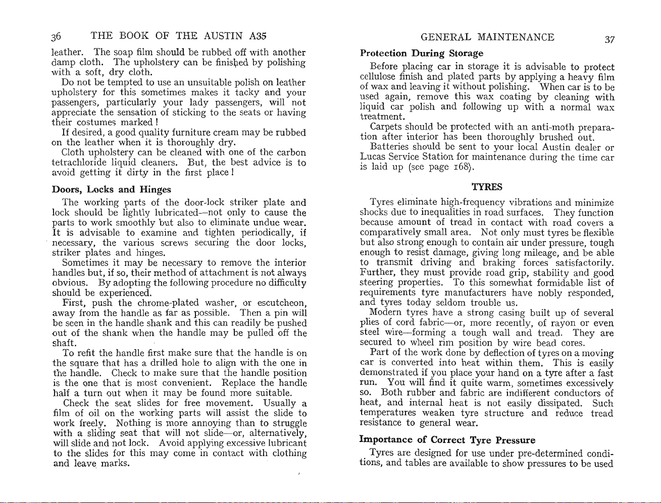
THE
BOOK OF
THE
AUSTI N A3S
leather. The soap film should be rubbed off with another
damp
cloth.
Th
e upholstery can be finishedbypolishing
with a soft, dry cloth.
Do not be t
uphol
stery
passengers,
a
ppr
eciate the sensation of sticking to
th
eir co
If
desired, a good qualityfurniture cream
on
the
thupholstery can be cleaned w
Clo
tetrach
empt
for this sometimes makes it
ed to use an unsuitable polish on leather
tacky
parti
cularly your lady passengers, will not
the
seats orhaving
and your
stumesmarked!
may
leather when it is
tho
roughly dry.
ith
one ofthe carbon
be rubbed
loride liquid cleaners. But,the best advice is
to
avoid getting it dirty inthe first place !
Doors,
Locks
The
working parts ofthe door-lock striker plate and
lock should be lightly lubricated- not only to cause
parts to work smoothly but also to eliminate
It
is advisable to examine and ti
and Hinges
un
ght
en periodically,
th
due wear.
. necessary, the various screws securingthe door locks,
s
tr
iker plates andhinges.
th
Sometimes it may be necessary to remove
handles
obvious.
but,
if so, their method of a
Byadopt
ingthe following procedure no difficulty
ttach
ment is
e interior
not
always
should be experienced.
the
First, push
away
from the handle as far as possible. Then a pin will
be seen in
outofth
haft
s
the
e shank whenthe handle
.
To refit the handle first
the sq
uarethathas a drilled hole to align with the one in
the
handl
e. Check to make sure thatth
is the one th
turn
half a
Check
out
the
film of oil on
work freely. Nothing is
with a sliding seat
will slide
to
and
and
the
slides for this
leave marks.
chrome-plat ed washer, or escutcheon,
handle shank and this can readily be pushed
may
be pulled off the
make
sure
thatthe
hand
le is on
e handle position
at
is most convenient. Replace the handle
when it may be found more suitable.
seat slides for free movement. Usually a
th
e working parts will assistthe slide to
not
lock. Avoid
that
may
mor
e annoyingthan to
will
not
slide- or,
app
lying excessive lubri
come in contact
strug
alt
ernati
vely,
cant
with clothing
gle
NERAL
GE
Protection
During
Before placing car in storage
cellulose finish and plated p
MAINTENANCE
Storage
art
37
it
is advisable to
s by applying a heavy film
protect
of wax and leaving it witho ut polishing. When car is to be
used again, remove this
liquid car polish and following up
atm
ent.
tre
Carpets should be
pr
otected
withananti
cleaning
with
a normal wax
-moth prep
with
ara
-
wax
coa
ting
by
tion after interior has been tho roughly brushed out.
att
eries should be sentto your local Austin dealer or
B
Lucas Service
Stat
ion for
maint
enance duringthe
tim
e car
is laid up (see page 168).
TYRES
Ty
res eliminate high-frequency vibrations and minimize
e
if
shocks due to inequalities in
because amount of
ati
compar
but
vely small area. Not only
also
stron
g enough to con
tr
road
surfaces. They function
ead in contact withroad covers a
must
tai
n air
tyres be flexible
underpr
essure, tough
enough to resist damage, giving long mileage, and be able
tr
ansmit driving and braking forces satisfactorily.
to
Furth
er,they mustprovide road grip, stability and good
ste
ering properties. Tothis somewhat formidable list of
requirem
and tyres
ent
s tyre manufacturers have nobly responded,
tod
ay seldom trouble us.
Modern tyres have a strong casing built up of several
tl
plies of cord fabric- or, more recen
steel wire
-formin
g a tough wall andtread.
y, of rayon or even
They
are
secured to wheel rim position by wire bead cores.
art
of the work donebydeflection of tyres on a moving
P
c
ar
is converted into heat withinthem. This is easily
demonstrated if you place your
run
. You will find it quite warm, sometimes excessively
so.
Both
rubber an d fabric are indiff
at,
and
int
ernal
hea
he
temp
eratur
es weaken tyre structure and reducetre
t is
han
d on a tyre after a f
erent
conductors of
not
easily dissipated. Such
ast
ad
resistance to general wear.
Importance
Tyres are designed for use
tions,
and
of
Correct Tyre Pressure
underpr
e-determined condi-
tables are available to showpressures to be used
Page 24
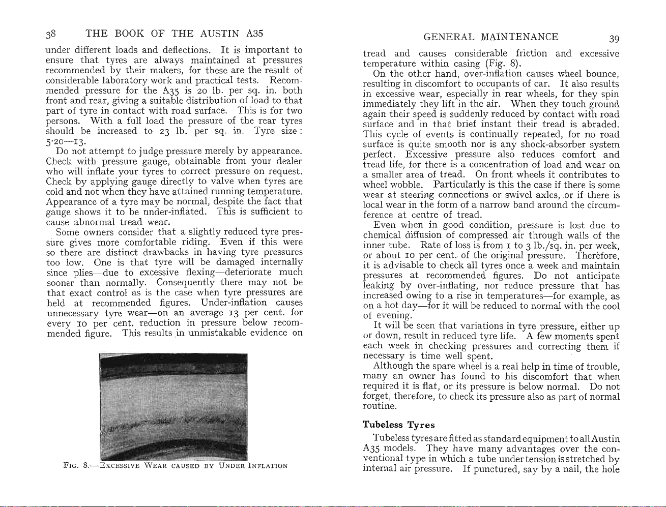
THE
38
under differ
ensure
thattyres are always
BOOK
ent
loads and deflections.
recommended by
considerable labor
mended pressure for
front and rear, giving a su
pa
rtoftyr
persons. W
e in contact
ith
a full loadthe pressureo~the
should be increased to 23 lb. per sq.
OF
THE
AUSTIN A3S
maint
th
eir
mak
ers, forthese are
ator
y work andpr
th
e A35 is 20 lb. per sq. in.
itab
with
road surface.
le di
act
str
ibution of loadto
It
is importantto
ained
atpres
sur
theresult
ical tests. Recom-
both
tha
Thi
s is fortwo
rear
Ty
re size :
tyr
Ill
.
5'20-13.
tte
Do not a
mpt to judge pres
Check with pressure gauge,
who will infl
Check
cold and
at
by
e your tyres to correct pressure on request.
app lying gauge directly to valve when tyres are
not
when they have attained
Appearance of a tyre may be normal,
it
gauge shows
cause a
bnor
to be nn der-inflated. ThIS IS sufficient to
maltread wear.
Some owners consider
sure gives more comfo
so there are disti
too low. One is
rt
nct
drawbacks in
thattyre will be damaged inte
since plies- due to excessive flexing- deteriorate
sooner than normally. Consequently there may
thatexact
contr
ol as isthe case when
sur
e merely by appearance.
obta
inab le from your dealer
runn
ing temperature.
desJ?it
~
the
fa~
t
tha
thata slig
htly
reduced tyrepres-
able riding. Even ifthis were
hav
ing tyre pressures
rna
lly
mu
not
tyre
pressures are
held at recommended figures. Under-infl ation causes
unnecessa
eve
mended fi
ry
tyre wear-on an average 13 per ce
ry
10 per cent. reducti
gure.Th
is results .m
0J.!
in
p
~ essur
e
unm
istakable evidence on
belo
:-v
nt.
for
recom-
ch
be
es
of
es
GENE RAL MAI
NTENANCE
39
tread and causes considerable fricti on and excessive
temperature
On
th
resulting in discomf
in
t
excessive wear, especially in r
imm
ediat elythey lift inthe air.
againth
surface and in
This cycle of even
within
e other h
casing (Fig. 8).
and
, over-infl
ort
to occup
ati
on causes wheel
ants
of car.
ear
wheels, forthey spin
Whentheytou
eir speed is suddenly reducedbyc
thatbrief inst
ts
is continually repeated, for no ro
anttheirtread
ont
It
act
boun
ce,
also results
ch ground
with
road
is abraded.
ad
surface is quite smooth nor is anyshock-absorber system
perfect . Excessive
pr
essure also redu ces comfort
and
tread life, forthere is a concentration of load and wear on
a
sma
ller
wheel wobble. P
areaoftr
t
wear at steering connections or swivel axles, or if
local wear in
ference
atcentr
ead. On front wheelsitc
arti
cularly is thisthe case ifthere is some
theform
of a narrow b
e oftread.
ontribut
and
aroundthe circum-
th
es to
ere is
Even when in good condition, pressure is lost due to
chemical diffusion of compressed air
inner
tube.Rat
or about 10 per ce
e of loss is from I to 3 lb.ysq.in. per week,
nt.ofth
e originalpres
it is advisable to check all tyres once a week and m
pressures at rec
leaking
by
omm
end
ed fi
over-inflating, nor reduce pressurethat
increased owing to a rise in temper
on a
hotday-foritwill be reduced to normal
thro
ugh walls ofthe
sure.Th
gur
es. Do not anticipate
atu
res- for example, as
with
erefore,
aintain
has
the
cool
of evening.
It
will be seen tha t
or down, result in reduced
each week in checking
ary
necess
is time well spent.
Although the spare wheel is a real help in time of
ma
ny an ownerhas found to his discomfort
required it is flat, or its pres
forget,
r
outin
the
refore, to check
e.
var
iations in
tyre
life. A few mom
pr
essures
sur
e is below normal. Do not
itspressure also as
tyre
pressure, either up
and
correcting them if
part
ent
s spent
troubl
that
when
of normal
e,
FIG
. S .-EX CESSI VE W E AR CAUSEDBY
UNDER
I NFLATION
Tubeless
Tub
A35 models.
ventional
int
ernal air pressure.Ifpunctured,
eless
Tyres
tyr
esarefitted as sta
Theyhavemany
type
in which a
tubeund
nda
rd equipment to allAustin
advantag
er tensionis
es overthe con-
stre
saybya nail,the hole
tched
by
Page 25
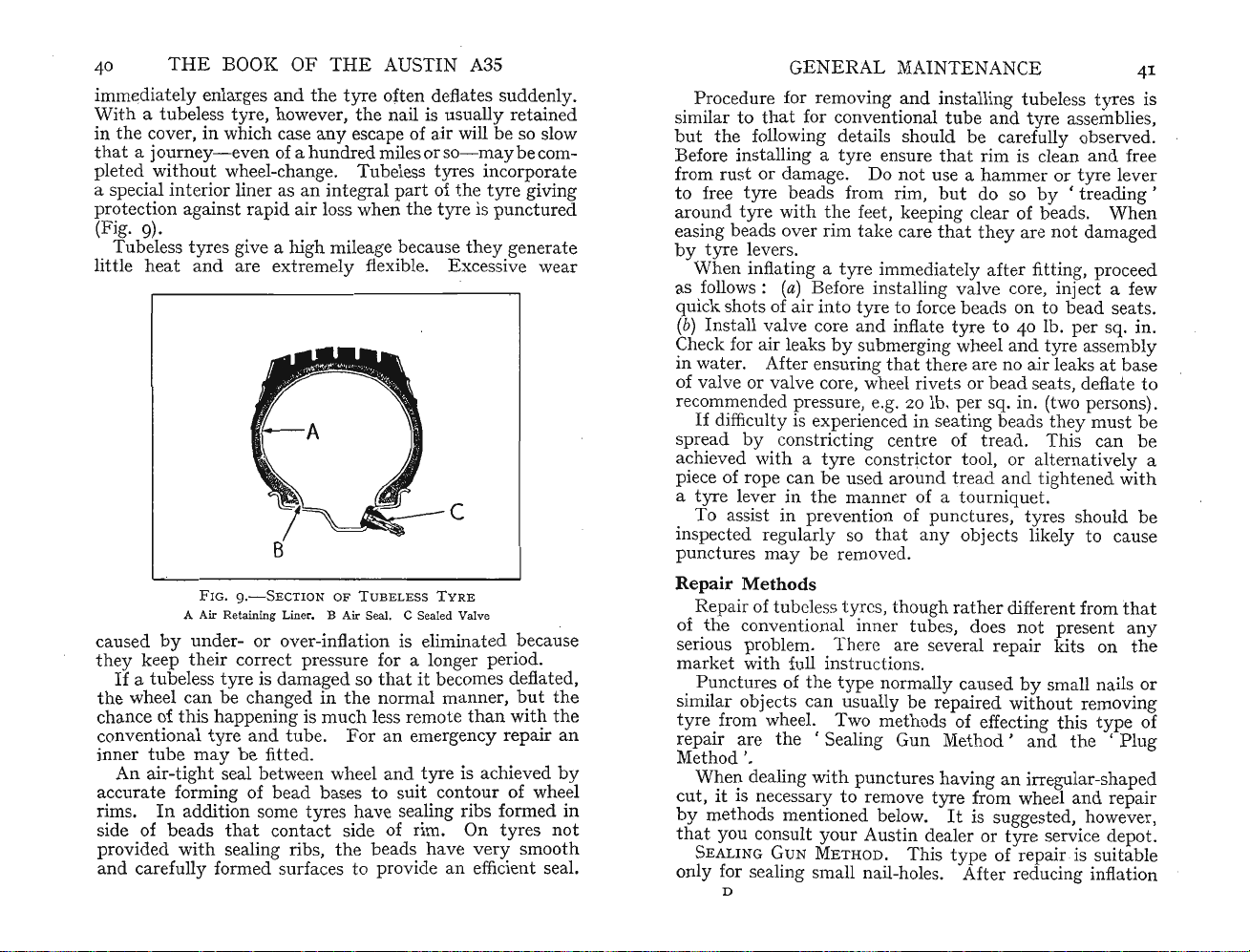
40
immedi
With
in
thata journe
pleted without wheel-change.
a special
protection against r
Fig
(
li
tt
caused
they
the
chance of
conventional
THE
BOOK
ately
enlarges
a tubeless tyre, however,
the
cover, in which case
y-ev
int
erior liner as an
OF
andthe
en of a
apid
THE
AUSTIN A3S
tyre
often deflates suddenly.
the
any
escape of
hundr
ed milesor
Tu
beless tyres incorporate
int
egral part of the
air loss when
nail is usually r
air
so-
the
tyre is punctured
. 9).
Tub
eless tyres give a high mileage becausethey generate
le heatand are e
FIG. g
A Air Retaining Liner. B Air Seal. C Sealed Valve
by
und
xtr
emely flexible. Excessive wear
.-SECTION OF T U BELESS T Y
er- or over-inflation is eliminated because
keep their correctpressure for a longer period.
If
a
tubel
wheel can be changed in
esstyre is
thishapp
tyr
dam
aged so
ening is
that
the
normal manner,
much
less remote
it becomes deflated,
e and tube. For an emergency repair an
inner tube may be fitted.
An air-tight seal between wheel and
ate
accur
rims.
forming of b
In
addition some
side of beads
provided with sealing ribs,
and
carefully fo
ead
bases to
tyr
thatcontact
es have sealing ribs formed in
side of rim. On
the
rmed
surfaces to provide an efficient seal.
tyr
e is achie
suit
contour of wheel
beads have
will
c
RE
than
very
etain
be so slow
may
be com-
tyre
giving
but
with
ved
tyresnot
smooth
ed
the
the
by
GENE RAL MAINTENANCE
Pr
ocedure for removing
similar to
but
that
the
for conventionaltube
following details should be carefully observed.
Before installing a tyre ensure
and
installing
and
thatrim
tub
tyre
is cl
eless
tyr
assemblies,
ean
and free
es is
from rust or damage. Do not use a hammer or tyre lever
to free
around
easing beads over rim take carethat
tyr
e beads from rim,
tyr
e withthe feet, keeping cl
but
do so by
ear
of beads.
they
are
not
'tr
dam
eading '
When
aged
by tyre levers.
Whe
n infla
ting
as follow
s:
(a) Before installing
quick shots of air into tyre to force
a t yre immediately
(b)
In
stall valve core and inflate tyre to 40 lb. per sq. in.
Check for air leaks by submerging wheel
in water. After ensuring th
atthere are no air leaks at base
of valve or valve core, wheel rivets or bead s
recommended pressure, e.g.
If
diffic
ulty
is experienced in seating beads they must be
by
spread
achieved w
constricting centre of
ithatyr
e constrictor tool, or alternatively a
piece of rope can be used ar
a tyre lever in
themann
20
ound
er of a tourniquet .
To assist in prevention of
that
inspected regularly so
any objects likely to cause
aft
er fitting, proceed
va
lve core, inject a few
bea
ds on to
and
bea
tyr
e assembly
eat
s, deflate to
d seats.
lb. per sq. in. (two persons).
tread
. This
tread
and
pun
ctures, tyres should be
tigh
tenedwith
can
punctures may be removed.
Repair
of
serious
mark
similar objects
tyre from wheel. Two methods of effecting
repair are
Methods
Repair of
the
tub
eless tyrcs,though r
ath
conventional inner tubes, does not pres
pr
oblem. There are several repair kits on
et with full instructions.
Punctur
es of
the
type normally causedbysmall nails or
can
usually be repaired w
the
' Sealing Gun Method ' andthe
er differentfrom
ent
ithout
removing
th
is type of
that
any
the
'Plu
Method '.
When dealing
cut
, it is neces
by
methods mentioned below.
thatyou consult
S
EA
LIN
with
sary
your
puncturesha
to remove
Austin dealer or tyre service depot.
vinganirregular-shaped
tyre
from wheel
It
is suggested, however,
G GUN METHOD. This type of
and
repa
ir is suitable
repair
only for sealing small nail-holes. After reducing inflation
D
41
be
g
Page 26
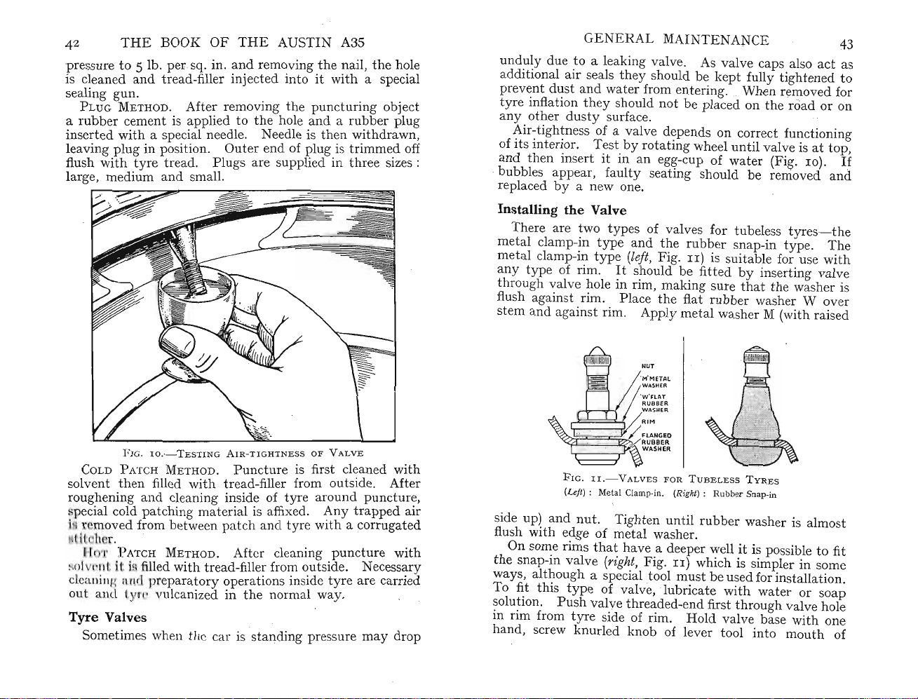
42 T
pressure
is cleaned
sealing
PLUG ME
a
rubbercement
inse
rted
HE
BOOK
to
5 lb. per.sq. in.
and
tread-filler injected into It W
gun
. . bi
THOD.
OF
After removing the
is applied to
with
a special needle. Needle IS
leaving plug in position.
tr
ead.
flush with tyre
Plu
large, medium and small.
THE
AUSTIN
and
r
em~
vin
g
pun
the
hole .and a ru"?ber plug
Out
er end of
I?lU
gs are supplied m
A3S
.the ?-ail,
th~n~Ithdrawn,
g.IS
Ith
ctunng
tnmme
threeSIz
the
h~le
a special
0 ject
.d off
es :
GENERA
L MA
INTENANCE
unduly due to a leaking valve. As valve caps also
additional
prevent dust and water from
tyre inflation
any
Air-ti
of
itsint
andthen ins
bubbles appear, f
air
sealsthey should be k
th
oth
er d
ghtn
ey should not be placed onthe road or on
usty
surface.
ess of a valve depends on correct functioning
erior. Testbyrotating
ertitin an egg-cup of
aulty
ept
fully
tight
ent
ering. . When removed for
wheel
unt
il valve isattop
water
(Fig. 10).
seating should be removed
replaced by a new one.
43
act
as
ened to
If
and
,
FIG
. l o .
-TE
STINGAIR-TIGHTNE
COLDPATCH M
solv
entthen filled with tread-filler from outside. After
roughening
pecial cold patching maten
ETHOD.
and
c
~eaningi~sid~
Puncture is first
al ISaffixed. Any
i r moved from between patch
l (
hr.
r 'I'
I
~()I
clcalliJl~
o
ut
Tyre
Sometimes when
ATCHMETHOD. After cleamng ,Pu
( II ;i. filled w
fi n l pr
an l
1.
I •
ith
tread
pa
ratory oper
1.1
1 anized inthe norm al
-filler from outside.
ati
Valves
tit
ar is standing pres
SS OFVAL
VE
cl~an
of tyre around
trapped
and
tyre
with
a corrugated
. . h
ncture
Necess~
ons inside tyre are carried
way
.
surema
ed
w
ith
punctur
~,
air
WIt
ry
y drop
Installin
m
m
any type of rim .
th
flush against rim. Place the flat
g theValve
There are two types of valves for
eta
l cl
amp
-in
et
al cl
typeand
amp
-in type (left, Fig.
It
the
rubb
II)
should be fitted by inserting valve
belesstyres
er snap-in type.
is suitable for use with
-the
tu
rough valve hole in rim , making surethat the washer is
rubb
er washer W over
stem and against rim . Apply metal washer M (with raised
NUT
'M'METAl
':~SlHAE
;
RUBBER
WASHE R
~
~~~§~RIM
~
~~~r
FIG.lI.
(Left) : Metal Clamp-in. (Right) : Ru bber Snap-in
side up) and
nut
flush with edge of
On some rims that
the
snap-in valve (right, Fig.II) which is simpler in some
ways, although a special tool
To fit this type of valve,
solution.
in rim from
hand, screw
Push
tyr
knurl
/ FLANGEO
RUBBER
~
WASNER
- V A LVES
. Ti
metal
valve
e side of rim .
FOR
T UBELE SSTVRE S
ght
en until
rubb
er washer is almost
washer.
hav
e a deeper wellitis possible to fit
must
beused for installation.
icate with
Hold
valve base
thread
lubr
ed-end first
ed knob of lever tool into
wat
throu
gh valve hole
er or so
with
mouth
one
Th
ap
e
of
Page 27
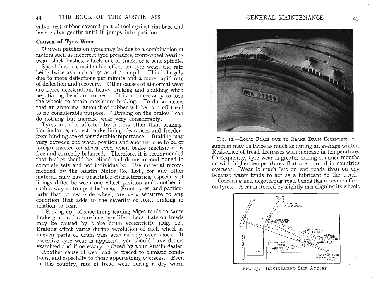
44
valve,
lever valve gently
THE BOOK OF THE AUSTIN A3S
rest
rubber-covered
part
of tool against rim base
untilitjumps
into position.
and
CausesofTyre Wear
Uneven patches on tyres
factors such as incorrect
wear, slack
bush
es, wheels
Speed has a considerable effect on
being twice as much at 50 as
due to more deflections
of deflection
are fierce
and
recovery.
acceleration,heavy
negotiating bends or corners.
the
wheels to
that
an abnormal amount of
att
ain maximum braking. To do so means
to no considerable purpose.
do nothing
but
increase wear
Tyres are also affected
For
instance, correct
from binding are of considerable importance. Braking
vary
between one wheel position arid
foreign
free
that
complete sets
mended
material
matter
and
correctly balanced. Therefore, it is recommended
brak
on shoes even whenbrake mechanism is
es should be relined
and
not
bythe Austin Motor Co.
may
have unsuitable characteristics, especially if
linings differ between one wheel position
way
such a
larly
condition
as to ups et balance.
tha
t of near-side 'wheel, are
that
adds to
may
be due to a combination of
tyre
pressures, front-wheel bearing
out
at
per
minuteand
Oth
of track, or a b
tyre
30 m.p.h. This is largely
er causes of abno
wear,
a more
ent
rapid
rmal
spindle.
the
wear
braking and skidding when
rubber
'Drivin
by
brake
lining clearances
Itisnot
very
factors other
and
necessary to lock
will be
g on
consider
anoth
torn
off
tread
thebrakes'
ably
.
than
braking.
and
freedom
er, duetooil or
drums reconditioned in
individually. Use material recom-
Ltd.,
for
any
other
and
another
Front
the
severity of front
tyres,and
very
sensitive to
particu-
braking
rat
rate
can
may
any
relation to rear.
, Pick
brake
may
ing-up'
grab
be caused
of shoe lining leading edges tends to cause
and
can reduce
by
brake
tyre
life. Local flats on
drum
eccentricity (Fig. IZ).
tread
Braking effect varies during revolution of each wheel as
uneven
excessive
partsofdrum
tyre
wear is
examined and if necessary replaced
Anoth
tions,
er cause of wear can be traced to climatic condi-
and
especially to those appertaining overseas.
in this country,
pass alternatively over shoes.
appar
ent, you should have drums
by
your
rateoftread
wear during a
Austin dealer.
Even
dry
warm
GENERAL
MAINTENANCE
45
e
F IG . 12
.-LoCAL
summer
may
Resistance of
Consequently,
or
with
higher temperatures
overseas.
because w
in
Cornering and negotiating road bends has a severe effect
tyr
on
ater
es. A car issteeredbyslightly mis-aligning its wheels
FL
ATS
DUE
TOBRAKE
DRUM
E CCE NTR
be twice as much as during an average winter.
tread
decreases
tyre
wear is greater during summer
Wearismuch
tends to
with
increase in temperature.
that
are normal in countries
less on
act
wet
as a lubricant to
roads
months
than
on
thetread.
lCITY
dry
in
s
If
CE
NTREOFTuRN
W IT H 1\,10S LIP
A NG LE
FIG.13.-ILLUST
RATINGSLIP
A NGLE S
Page 28

THE
BOOK
relative to direction of
tyres as to
incr
ease rate of w
and
front
otherfactor
s (Fig. 13).
Whendrawingupto
should be exercised to
ctures'
fra
thisdam
a
nyth
absorbed by t
causing
age is caused wit
ingunu
sual
yr
e and roadsprings .
OF
THE AU
tra
vel.
Thi
ones. Re
ear
sultin
according t o speed, load,
kerb
prevent
dam
age
hout
has oc
curr
s applies equally to r
g tyre slip and dist
, or
parkin
what are known as '
to
casing cords. S
owner being
ed,
init
cover when first signs of damage are
may suddenly fail c
di
sastrou
and
s re
It
is ofthe grea
thi
sultsifyour
s detail should be regul
Mis-alignment causes l
al
readym
t
ha
enti
t of line oftravel.
Keep an eye on fr
tr
eads.Duetothe'
will w
ear
mor
dition such as '
omplet
ely
anda'blow-out'
aretravelling at speeds.
testimport
oned, n
atural
ont
ancethat
arl
at
eral wear ontread because, as
y checked (see page 57).
direction
tyr
es andpart icularly ontheir
camber ' of the fr
e on one side
feath
er-edges'(Fig. 14), oruneven p
thanthe
STIN
A35
ortio
road
camber
g against it,
impa
ometim
awareth
ial shock
It
is desirable to
noti
havi
ced, for
ng been
ren
laterit
can
wheels are aligned
of whee l differs from
ont
wheelsthetread
otherbut
any con-
atch
ear
car
ct
es
at
ew
have
es.
NER
GE
should be suspect.
n
e
by drawing
thentheoth
and
thenth
Une
of
fact
ing
wear, slack swivel-pin bushes, wheels
ent
b
Whe
mak
e. A set of
of miles and
and
an inferior one is really trifling. An inferior
let
you
feel it was
th
e fingers acrossthetreadfirstin one direction
e wheel to e-in requires corre
ven
patch
ors such as inc
spindle.
n bu ying new tyres always buythose of a known
the
downata most inconveni
not
AL MAINTENANCE
'Feat
er.
If
es onthe
orr
tyr
es will
her-edges ' can be f
a di
stin
ctly sharp edge can be f
cting
tyr
es ma y be
ect tyrepres
norm
ally
due
sur
run
elt
on a tyre
(see page 58).
to a combination
e, fro
nt-wh
eel be
outoftra
many
thou
ck, or a
difference in cost between a good make
tyr
e may
ent
mom
ent
really so cheap
aft
er all.
andthen you
47
elt
ar-
sands
Equalizing Tyre Wear
To equalize tyre wear it is a good plan every 5
ont
to change fr
wheels to rear.
on any individu al tyre by compe
of we
ar
experienced in fr
spar
Also, bring
to
allow a new spare tyre t o remain idleuntil other tyres
e wheel
are being worn out as it
Diagonal
int
erchanging between near fr
intothis
may
and between off frontand
most
ro
tation
satisfactory
for each wheel (Fig. 15).
alte
rnati
ont
Thispr
nsa
andrear
eventsundue
ting for different kinds
plan, foritis
deterior
atefrom
near rear position,
on, for it reverses
,0
00 miles
wear
wheel positions.
bad
policy
lack of use.
ont
and off
prov
directi
ides
lear,
the
on of
F I G. 1 4
.-'
F E ATHE R
EDGE'
DUE
TO
WHEEL
M IS -AL
IGNME);T
FIG.15.-T
YRE RE-P O
SITI
ONI N G
Page 29
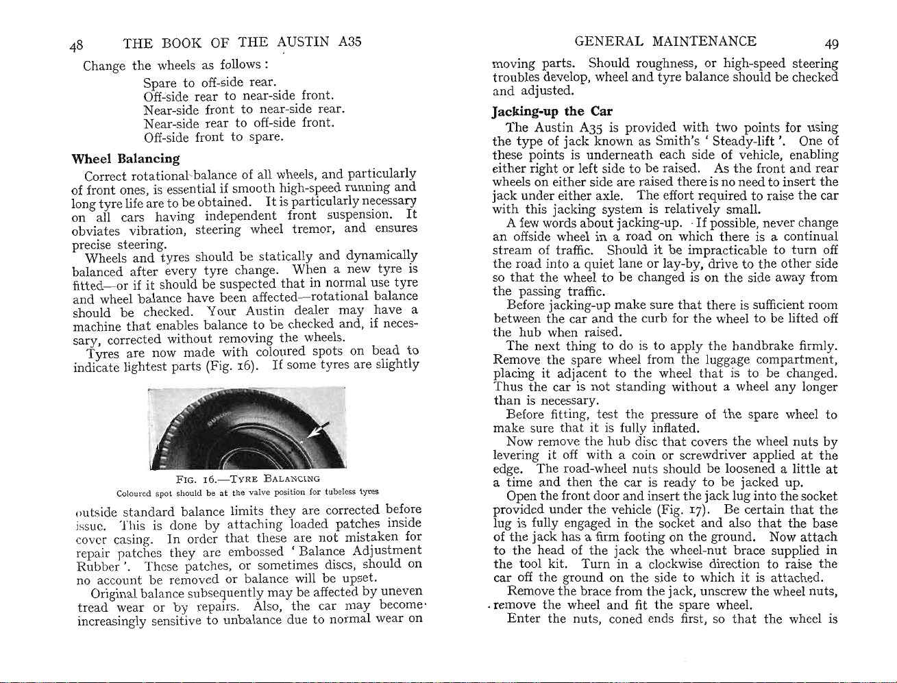
4
8
Change
THE
BOOK
the
wheels as follows :
OF
THE
AUSTIN A35
Spare to off-side rear.
Off-side rearto near-side front.
Nea
r-side front to near-side
Near-side rearto off-side fro
rea
nt.
r.
Off-side front to spare.
Wheel Balancing
Corr
ect
rotational-balance of all wheels, and
of fr
ont
longtyre life are to beob
ones, is essen
tia
l if smooth high-speed
tai
ned.Itis particul
on all cars having independ
ent
front suspension.
part
icula
runningand
arl
y necessa
rly
ry
obviates vibration, steering wheel tremor, andensures
precise s
tee
Wh
ring.
eels and tyres sho
uldbesta
tically and dynamically
balanced after every tyre change. When a new tyre is
fit
ted-or ifitshould be sus
pect
ed that in normal use tyre
andwheel balance have been affected- rotationalbalance
should be checked. Y
machinethat
sary, corrected
Tyr
es are now mad e w
indicate li
enables balance to be checked and, if neces-
with
ghtest
part
Coloured spot should be a t the valve position for tubeless tyres
FIG. r 6
outside standardbalance
issue, This is done
cov r casing.
In
repairpatchesthey are embossed
Ru
bber '.
Th
ese patches, or sometimes discs, sho
no accountbe removed or b
Original balance subsequently may be affectedbyun
t
read
wear or by repairs. Also,
increasingly sensitive to
our
Austin dealer
out
removingthe wheels.
ith
coloured sp
ma
y have a
ots
on bead to
s (Fig. 16). 1£ sometyres are sli
.-T
Y RE BALANCI
limitsth
byattac
hingloaded
orderthatthese are
alan
unb
alance due to normal wear on
NG
ey are co
rrecte
patche
not
'Ba
mistaken for
lance Ad
ce will be upset .
the
car
may become'
ghtl
d before
s inside
justmen
uld
even
It
on
GENERAL
mov
ing
parts.
tro
ubles develop, wheel
and
adju
sted.
Should
MAINTENANCE
roughness, or high-speed steering
and
tyre
bal
ance should be checked
49
Jacking-up the Car
TheAustin
the
type
t~ese
p
?intsisund
either n
wheels on ei
jack
under either axle.
withthis
A fe'Ywords
an
offside wheel in a road on which there is a con
str
eam of traffic. Shoulditbe
th
e roadinto
so
thatthe wheel to be changed is on
A35 is pro
of jack known as
ght
or l
eft
side to be raised. As the fr
thersidearerai
jac
king system is
ab?ut
erneath
Th
jackin
vid
ed with t wo
Smith's'Stead
each side of
sed
ther
e is no need to ins
e effort
relat
ively small.
requ
point
y-lift'.
vehi
ired to raise
g-up. .~fpossible, never change
impr
act ic
abl
a quiet lan e or lay-by, drive tothe other side
the
side
s for using
One of
cle, enabling
ont
andrear
ert
the
the
car
tinu
e to
turn
away
from
al
off
the passingtraffic.
Before jacking-up
betw
een
the
the
hub
Thenext
y
Re~ov
placmg It
Thus
the
car and
when raised.
thin
e.
th
e
~pa
adjac
carisnotsta
mak
e sure
thatthere is sufficient room
the
curb
forthe wheel to be lifted off
g to do is to apply th e h
re
wheel fromthe luggage compartment ,
ent
to the wheelthat
nding
with
out
andbrak
e firmly.
is to be changed.
a wheel
any
longer
thanis necessary.
Before fitting,
test
the pressure of
the
spare wheel to
make surethatitis fully inflated.
No.w re
lev
edge.
a
time
Openthe front door
pro~d
lug IS fully engaged in
of
t
to
the
car
Removethe br ace from
. removethe wheel and fitthe
Enterthenut
!l1
0ve
th
~
hub
enn
g It off WIth a com or screwdriver applied at
The
road-wheel
nut
and then the car is r
di.scthat
and
ins
ed
underth
e vehicle (Fig. 17). Be certain
the
the
jack
has
a firm footing on
the
hea.d of
tool kit. T
the
j.ackthe wheel-nut
urnina clockwise dir ection to raise
coversthe wheel
s sho
uld
be loosened a
ead
y to be jacked up.
ertthejack lug
socket
and
the
ground. Now
into
alsothat
brace
offthe ground onthe side to whichitis a
thejack, unscrewthe wheel
spar
e wheel.
s, coned ends first, so thatthe
nuts
by
the
littleat
the
socket
that
the
the
base
att
ach
supplied in
the
ttac
hed.
nuts
wheel is
,
Page 30

50 T
HE
BOOK
OF
THE
AUSTIN
A3S
CH
APTE
R IV
STEERING GEAR
FIG. I 7 .- S MITH'S ' S T E ADY-LI F T '
correc
tly
cent
ralized. Slightly tighten up each nut diagonally, a l
evenly against the hub.
Lower
clockwise and so release arid detach the jack.
Finally,
and
Check
e
nd
indefinitely.
ittl
e at a
th
e car to t he groundby
tightenthe wheel
fitthe disc cover.
thenut
ofthe day, after whichthey should remain secure
tim
e, to ensure thatthe wheel seats
nut
s with
s ofthe wheel you have just fitt ed atthe
JA
turningth
the
CK
e brace anti-
wheel-br ace
HE STE ERING
cam-and-lever
T
manceuvrability when neg
steering box, which is mounted just forwa rd of
provides a short st eering column of great rigidity. A crosstube runs beh
anism ample protection. .
The lower e
a cam m
th
e double lever is
endwith
th
e cam groove.
th
As
in
th
e cam.
th
e double lever andthis, in
linkage
Inthe steering linkage, which has independ
wheel suspension, one of
tubes-i
lever of the steering gear.
swivel arm of
th
e double lever is conn ected
movement to
an
idler shaft and bracket. This is bolted tothe
memb er, symmetrically opposite in mounting to
ing gearbox, again
thi
s idler lever is another side-tube connected to
by
way of its swivel arm.
steering gear to
side-tubes
to normal road inequalities, any deviati ons will be equal
for each wheel.
Th
e working
Pro
viding
will be enjoyed before any
indthe engine and gives the steering mech-
ndofth
ount
ed onball races.
a conically shaped pegpressed i
e steering shaft is
Thi
andfront
s connec
theright-h
the
-e
nsures
thatthe level is correc
GEARofth
typ
e with a r
e steering inner column terminates in
bolt
ed has a s
s p
ted
th
e front whee
part
turn
artly
rotatesth
wheels.
thetu
directly tothe front arm ofthe double
and
left-h
and
with
a double lever.
Thi
tha
t as each wheel rises and falls, due
s of
the
adjustm
e Austin A35 is of
ati
o of
12:I,
giving easy
oti
ating sh
Th
hort
ed,the peg followsthe groove
turn
It
s other
wheel. To
the
wheel
s m
ls-
steering gear operate in oil.
tlymaint
51
arp
corners. The
th
etoe-board,
e rocker sh
cam leveratits
e rocker shaft moving
, actuatesthe steering
bes- referred to as side-
end
cross-tube .
throughthe
ethod
through equally
ent
is required.
aft
nto
contact with
is joined to
the
rear end of
It
Fromthe rear of
of connectingthe
ained, long service
the
to which
inner
ent
front
the
tran
smits
medium of
oth
er side
th
e steer-
the
wheel
mount
ed
Page 31

52 T
The
is of
eliminate
The
strongly
should ask your Austin dealer to ca
skilled a
heavy steering
HE
BOOK
OF
THE
AUSTIN A3S
linkage connectingthe double lever andcross-tubes
the
ball-and-socket
any
steering
other
box
adv
ised thatif
tte
mpts can cause ti
and
typeand
attention
regular lubrication will
for a considerable time.
has adjustments for wear but it is
adju
stment becomes necessary you
ght
accelerated wear or 'back
adju
rry
stm
this
ent
-lash'
movement), contributing to ' steering wander '.
It
may bethat
m
ent
yourself, however,
fully followed you should be able to do it
you find it necessary to effect some
andifth
ese instructions are care-
sati
Before adjusting, it is desirable to ascertain e
wear is pres
symptom is either excessive
before th e r
wobble or ' w
linkage wear and
test should disclose
Hav
way
and then the
from moving sideways. Note
th
e steering linkage connection . Do not forget
connections are held
and
double levers.
wear oval.
will not correct as a
Assume
Grasp the double lever
pushed, so
away from
th re is an adjustment whereby it can be
the side cover to
with a loc
fully tu rn
untilth
is so constructed
wheels are directed straight
adjust
will be unduly stiff
When
tighten
ent
and whereithas
oad
wheels move, or a tendency for wheel
and
er'
not
th
e someone slowly
oth
er whilst you prev
in tapered holes in the swivel-arms
Thi
If
s is a condition
tru
the
wear is found to be inthe steering box.
bri
ngingthe end in
the
cam.
movement
to develop. This may be due to
to wear inthe box.
e source ofthe
turnthe steering wheel first one
allowed to become loose,they
e seating isthen no longer possible.
and
If
movem
taken
at the
troub
ent
any
signs of lost motion
that
subsequent
see if
thi
s can be pu lled
the
box
nearer to or further
ent
is found at this
place. The first
ste
The
le.
the
tak
wardsthe
knut
fitted to it. Loosen
theadju
e end-flat is
thatthere is least ' back -
sting
top
is a hexagon-headed screw
thi
s locknut
screw clockwise a littleata
take
n up . Rememberthat
lash'
ahead.Ther
efore, always
withthe wheels in this position otherwise
atthe c
th
e correct adjustment has been obtained securely
the
locknut
makingsurethe screw does
entra
l position.
out.Un-
resulting in
(undue
adju
st-
sfactorily.
xactly
what
ering wheel
following
road
wheels
that
these
may
tight
ening
and
point
en up. On
and
care-
tim
the
cam
when
the
the
steering
not
turn
STEER
any
more. Re-checkthe adjustment in case this
pened.
It
is permissible forthe st eering gear,
wheels jacked up, to have very sli
position
wheel shaft. This
wheel firmly with
but
there
Another point
must be no
at
which th ere may be wear is
may
bothhandsandbyalt
down and pulling up along
end-float is felt, it will be necessary to remove
gearbox end cover to
ING
GEAR
ght
undu
be gauged by
th
e len
ext
ractthe
' d
rag'
e resistance.
gra
sping
ernately pushing
gthofthe
adju
stm
with
at this
the
the
column.
the
ent
has
hapboth
centra
steering-
steering
steering
shims.
53
l
If
At the lower end of the steering box is a hexagon gland
nut.
It
locks
the
position. Provided
thatthe end cover is marked so
a known edge is to the top, the stator
long stator
tub
e in its correct relative
tube
need
not
tha
t
be
further removed.
As
the
removal ofthe end p
escape, use a receptacle to prev
late
will allow the oil to
ent
messing
the
floor.
RemovalofShims
Unscrew
at
downwards slightly, disclosingthe
between it
types-s-brass and steel. Remove one
th
e removal of each,' bolt up
they
at
a time
the
four bolts of th e end p
late
adjustm
ent
andthe steering box. These shims are of two
at
plate
a time
and
are not removed
may
und
uly ti
the
end
thu
s the elimination of several shims
ghtentheball rac es causingthem
and move
shims fi
and
re-test.
tte
after
it
d
If
to wear rapidly as well as making the steering stiff. Should
you suspect
thatthe
bearing ad
justment
appears to be too
tight, a quick check ma y be made by loosening slightly-
say half a
If
the steering now appears to be free it indicatesthat
many
numb
e
A stiff steering gear is sometimes
itself having been strained and
turn
each-th
e four end-cover securing bolts.
shims have been removed.
er must be refitted to
obt
too
Ther
efore, a suitable
ainthe correct adjustment.
trac
eable to th e column
out
of position.
Try
the
effect of loosening the column -support bracket allowing the
column to move into its normal
th
e column in
mounting
can
be bolt ed into position without placing any undue
thi
s position is now free,the steering box
and
bracket should be set sothat
unrestrict
ed position.
the column
If
constraint on it.
Page 32

54
Th
e correct
THE
BOOK
ste
ering adju
OF
TH
E AUS
stm
ent is when a very sli
TIN
A3S
ght
, dr ag ' is felt asthe steering 'Yheel isturned from lock to
lock withthe front wheels raised.
Do notforget thatremoving the end-plate will have
allowed allthe oil in th e
box
to escape.
Th
erefore, refill
the box to level of orifice.
Overhauling Steering Gear
Possiblythe owner
steering gear when adj
The same
adv
ice
work unless you feel you
At the outset it should be
necessary for the removal ofthe steering wheel
double lever. B
hazardatte
mpts to remove them without
will either be abortive or will cause d
If
you have decided to dothe work yourself, first
out emblem cap set in hub of steering wheel by ge
prisingitwith
wheel
securing c
nut
and
astellatednut
shaft. A special
offits tapered m
Unscrew
box.Dr
Before
f
our
Ex
tractthe key onthe steering-wheel
the
inner column out of the stee ring-column tube. The
major
deta
il (Fig. 18). . .
In
a press fit in
splines
In
boltsat
aw rocker s
the
bolt
steering inner column can be dism
s holdingthe end cover mustbe un screwed.
part
s ofthe steering gear may now be inspe
spect the rock er shaft for wear onthe ball peg.
the
and
if anyare
spectthe face againstwhl.ch the
for it mayhave been scored If at some
gear
has
sufficient
been
lubricant.
deepthe face can be restored by carefully grinding.
may
find it necessary to ov
ustmentno longer becomes
app
lies here also
hav
point
-do
e sufficient
ed outthat
not
erhaul.
effechv~.
attempt
mech~nic
al
skill.
special tools are
and
othparts are secured ontapers
and
proper tools
ama
ge.
a screwdriver. Nextunscrew
withdr
aw washer. Remove
holding double lever to
extractor
ounti
will have to be used todraw
ng. . .
edges of side cover
haft
out of
itsbushes insteering box.
and
s
cotterpm
lift
It offthe
teer
rock
antledthe
tap
er and draw
cted
lever an d ISreplaceable. Look for twisted
T~l
found
the
shaft.
must
be renewed.
adJus~
mg
screw
adjusted
Pr
t<:>o
. tightly or
oviding thatth
tim
e the
operat
e scon ng IS not too
e~
ab~ts
st~en
WIthout
it
the
thi
the
hap
tak
l?-t
ly
m~
thi
S
ng
~
at
on an oil sto ne. Atthe same time exammethe adJl;lstmg
screw for similar signs of wear and if necess
ary
treatinthe
s
-
e
~r
s
in
IS
ST
EERING
same way.Inspect the rocker shaft for wear at th e po
where it is mounted in its
cam for wear inthe grooves andattheb';l
its
bearings. Wear at either ofthese
GEAR
bea
ring bush. Also, inspect
.ll
tra~k
pomtsWIll necess
55
int
the
s
th
at
~
orm
itate
renewing the unit. .
Th
e corresponding ball cups should be
wear and if they are p
cup
s are replaceable.
Th
oroughly wash allparts
ittedth
ey shou ld be renewed. Both
ready for reassembly.
exam
ined for
Reassembling
In
spect
the
s
cork gland atthe
haf
t and replace if necessary. It IS securedinposition
o u~side
endo~th
e
~r?ss
by a steel washer to be retained in place by lightly peening
over the metal at three points around its circumference.
Pl
acethe steering outer column in the vice so
end of th e box is pointed
end to the bo
ttom
upward
s with the steering-wheel
.
that
the
Assemblethe ball cages and cups (if removed) and install
th e inner column. Refitthe end cover
and
shims, ti
ghten-
ingthe four bolts securely. .
Temporarily reassemble
end floator, alte
alsopage 53).
rna
tively, for too ti
Th
e c
no end floatbutjust
the
stee~mg
orr
ect adjustment is when there is
wheel.
ght
and
an adjustment (see
test for
a slight ' drag '. Remove or add
shims between the ste ering box and end cover until this
s
ett
ing is achieved. "
The upper bush- ju t
replaceable
aft
er very consid
Th
but
is scarcely likely to require renewal except
erab
e upper shaft bush is of a felt material. A new
should be firstsoaked in engine oil
one corner between the inner column and outer
Th
en g
radually work the remainder
screwdriver or similar tool.
ite tothe p
steering
artofthe
sha
ft. Apply a few
le use.
felt
b~neath
that
the
~
teenng
and
ins
ert
ed bypushm
int
It
is advisable to ap ply graph-
drop
o position with a
makes
~onta
ct
s of oil here every
wheel-s-is
~
elt
tub
withthe
50
miles.
Next, oil th e rocker sha ft
and
ball peg and .insert
into
position in the box, the peg to enter th e groove m the cam.
Und
o the loc
the'adju
knutofth
e side cover plate and screw bac k
sting screw several
turns
..
g
e.
0
Page 33

T
HE
BOOK
FI
G. I S
I Steering-wheel Securing Nut. 2 Felt
Shaf
t. S Housing for Gear. 6 Side Cover. 7
screw Locknut and10Screw. I I Cover Set-screw, 1 2 Side-cover Joint and 13
cover J
only).
I 9 Set-screw
2 2 Retaining Disc.
Oil
.-COMPONENTSOFCAMTYP
oint
Washers.I4R
I 6 Bearing Ball Cups and Balls. I 7 Shims for Adjustm
and
Washer
23
Steering Side
the
surfaces of
wherethey touch one an
Fit
a washer between the
OF T
HE
AUSTIN
Bush
uhber
Ring forISTop Bearing Retaining Cup (for assemhly
.20Cam
and
Inn er Column . 2I Cork Sealing Washer.
and
Cross-tube Lever.24Lock or Plain Washer-,
25 Nut
and
the
adjusting screw
oth
er.
box
E S T
for Inner Column. 3 Peg,
Washer
and 8 Oil-Filler Plug. 9
Split
Pin
and side cover
A3S
EERIN
ent
and
G UNIT
. I 8End Cover.
and
cross sh
and
it up securely,
that
Refit the double lever noting
are
mark
ed to ensure reassembly on
Tighten up
new
cotte
the
r pin.
castellated
nut
bothitand
the
and
lockitsecurely
the
correct splines.
with
4 Rocker
Thru
En
aft
bolt
shaft
Adjust
so
th
thatat
the steering
Refit
th
STEER
e rocker
thecentral
at
this
e steering gear in
ING
GEAR
shaft
by means of
the
positionthere is no end fl
point
stiff.
the
reverse manner from
adju
sting
oat
screw
nor
that
57
is
when removing.
One or two points require care, however. Do
up
the
thr
ee bolts holding the steering box tothe side
member until the strap at the in
strum
ent
nottighten
panel has been
assembled.
When
reconnecting the steering linkage, t ake carethat
the
tap
drop
arm
are clean andthatthe
If
th
e steering-box bolts are first ti
thatthe steering column will
If
ers onthe connection and in
secured in
thi
s m
ann
er it will be stiff
not
the
out
ght
er end of
ened it
ght
may
nut
is pinned when ti
line up with the bracket.
and
undu
e bearing
the
.
be
wear may ensue (see also page 53).
e-attachthelighting
R
switch to the steering column.
Adjusting Front Wheel Toe-in
For
technical reasons, into which it is not necess
enter,
th
e front wheels must either be exactly parallel or
ary
to
point towards each other slightly at the front. An equivalent measurement , taken at
wheels, is
16
in. to i in. less than at
They must not toe-in more than
will result
andthe steering itself will
nor as responsive as
th
ere is consid
era
ble toe-in or toe-out,itmay be thatone
wheel has been bu ckled slightly or possibly the tyre is
ru
st-
d-
a
nning true. Before proceeding further in such cases, it
is as well to spin each wheel to establish if any of the above
conditions are
with
th
e wheels in
To
adju
end of th e cross
right-h
and
th
ese
nuts
in
th
e required direction. This will havethe effect of
moving b
according to
When
the
both
locknuts.
E
pr
esent. Always test for front-wheel toe-in
the
st the wheel toe-in loosen
tub
and the
other
looseitis only necessary to
oth
wheels nearer tog
th
e direction in which
correct se
tti
hub
hei
ghtatth
th
e rear (Fig. 19).
i in., otherwise
not
it
should be.
' straight-ahead ' position.
e rememberingthat
a left-hand
ng has been
If
it
the
turnthe cross
eth
er, or
the
obtain
does appear
locknut at each
thr
ed securely ti
e front of
be as ac
tyre
the
-wear
cura
tha
not
one end has a
ead. With all
tub
furtherapart
tub
e is
turn
ght
te
t
e
,
ed.
en
Page 34

58 T
It
out
HE
is a m
att
er of some difficu
special apparatus
devise a suitable
Cut
this
to such a lengthth
BOOK OF
mak
TH
E AU
STI
N A3S
lty
to mea
sur
but
you
may
finditpracticable to
e-shift gauge from a wooden strip.
at it will exactly enter
e toe-in with-
bet
ween
CHAPTER V
SUSPENSION
FIG. 19.-T
th
e tyre walls atthe front ofthe wheels. Provide yourself
wi
th
two rests sothat
on one
strip is a snug fit between
when similarly installed
th
ere should not be more
o E-INBETWEEN
at
each enditis at
Less
when
hub
atthe
WHEELRIM
th
th
an
the
heig
th
e wheelsatth
S. A is l .' t o t in.
B
wooden strip is resting
ht.
Assumingthe wood
rearofth
e front wheels
an k in. play.
e front
then
T IS ONLY NATU RALthat
performance of
I
ance
th
e question ofthe springing, or suspension, generally
th
eir respecti ve cars. Nextto perform-
owners should discussthe
is either praised or blamed. Th e suspension of a car is
not merely
oth
er factorsthat
contribute to comf
similar cars one
experience a some
an
owner who carries three passengers or an eq
the
method of springing used. There are many
whether taken singly or collectively
ort
able riding. For instance, on two
driv
er who may
what
differ
habit
ent
ually drive alone will
' ride'as compared with
uivalent
load. Therefore,the designer has to bear in mindthese
two extremes in producing a suspension system
und
be satisfactory
The Aus
tin
er widely
A35 is fitted with semi-elliptic
reverse camber leaf springs at
varyi
ng conditions.
th
e rear. Atthe front
is independent suspension employing large coil springs
und
that
erslung
will
ther
and
wish-bones.
R
~ad
Springs
Two factors
sion are neglected springs- these t
and
tyre pressure. Too Iow a pres
whilst too high a pressure tends to
and
that
Rear
Axle
hav
e a considerable bearing on suspen-
end
to become stiff-
sur
e contributes to roll,
pr
oduce pitching and
hard suspension generally.
Provided
thatth
thetyrepressur
sion should be found satisfacto
Each rear spring has eight leaves and between
four leaves
thr
squeaking andundue wear by virtue oftheir n
ua
rusting q
lities.
The spring eyes
requiring no lubrication. At
fitted, one end of which is
th
e other in a bracketattac
e spri ngs are lubricated regularly
and
es checked (seepage 38)the rear suspen-
ry
for all normal conditions.
thetop
ee zinc st rips are inserted. Theseprev
atur
al non-
at
each end have silent-bloc bushes
th
e rear a spring shackle is
carr
ied inthe silent-bloc bush,
hedtoth
.59
e chassis frame. This
ent
e
Page 35

THE
60
bracket loc
weekly
by
luggage co
lubricati
removingthe rubber plug si
BOOK
atingth
e s
on with the grease-gun. Access is
mpa
rtment floor.
F
IG.2o.-REMOVINGBUSH
OF
THE
AUSTIN
hack
le to the chassis frame needs
tuatedat
FROM
A3S
each side ofthe
SPRING
-EY
E
obt
ain
ed
SUSPE
wheel move upw
th anthe
sisted.
othe
Thi
ard
s or down
r, however,
s takes place because instead ofthe bar moving
up or down as a whole one end only moves
resistance isthen developed.
-t he anti-roll bar pr ev
and
tends to give
entsundu
steady
shock-absorber operation and
lat
er in
thi
s section.
NSION 6I
ward
then
and
s to a greater degree
thi
s movem
ent
and
From
this you will see
e side movem
entofth
smooth suspension.
maint
enance is described
will be re-
considerable
that
e bo
Th
Front Suspension
Ea
ch front wheel is
sion usually called t
lower arms
tak
e this
he'
sha
mount
ed on a type of fr
wish-bo
pe.
ne'
Thi
ont
suspen-
beca
usethe
upperand
s system permitsthe fr
ont
wheels to move up and down according tothe inequalities
of
the
road
surfa
eering geom
bon
e member
lar
ge helical compression spring in such amanner as to
etr
y shall exist. Betweenthe lower wish-
and
st
ce,atth
e same
the
chassis frame is fitted vertically a
tim
e assuringthat
correct
dy
e
Do not be tempted to
bushes
ing qualities.
underth
e i
In
mpre
actual f
app
ly any oil to
the
sil
ent
-bloc
ssion thatit will improvetheir wear-
act,it
will havethe reverse effect.
Rear Shock Absorbers and Anti-roll Bar
An ingenious, yet simple, dev ice is ?
to minimize body sway or roll such as IS caused by co
or abnormal r
of a steel
and
in fr
end and b
sides whilst a
oad
con
dit
ions. In effect,
barmount
ont
of the rear axle. An arm is extendedateach
olt
ed tothe h
ed acrossthe chassis frame
ydr
rubb
er-bushed link connects the endof each
aulic shock absorberatboth
tte
d to
this
the
rear a:cle
rne
device consi
parall
el to
ring
arm to the rear axle itself. (This device is illustrated in
Fi
g.
20
up
.) Suppose
ward
s. Sincethe
absorber levers, normal
far as r
ebound
the
car
hit
s a b
anti
umpthat
-roll bar is connected to
hyd
raulic
contr
and
compression are concerned. Should one
moves the axle
ol is obtained so
the
shock-
sts
3
FIG.
I SwivelAxle-pinTop Bush. 2 Swivel Axle-pin
2I.-FRO
NT
SUSPEN
Lower-link Bushes
SION
L U BRI C
ATIO
Bott
om Bush. 3 Suspension
N P OINTS
Page 36

62
cause
pad
from causing
shock absorber. Although
somewhat from
is
the
parts
service. - I t will be found
The
the
The
THE
BOOK
the
wheel to absorb
fitted
within
the
top
suspension to ' go
wish-bone
that
same.
upper
front
are
and
axle
lower wish-bone
beam. Provided
lubricated periodically
OF
THE
AUSTIN
road
shocks. A conical
this spring prevents abnormal loading
solid'.
memb
er incorporates a hydraulic
its
extern
fitted on
the
al appearance differs
rear
axle,
arm
that
takesthe
the
they
should give good
thatatsome points there are
rubber bushes. These require no lubrication
bearings fitted
ally where
are
two lubricators, one ben e
other
above lower wish-bone
Swivel axle
friction caused when wheels
steering wheel is
axle bearings
reference
Checking for
Shoulditbe suspected
suspensionthe following
the
trouble. First, wedge
will
not
front wheels, oneata
Grasp
the
otheratthe
if
movement
king-pin bushes oratthe
ings
have
thebrake
By grasping
position
wear in
the
where a friend to look
In course of time, a little wear
bushed ends of
bushed ends.
with
lubricators
th
ey meet axle swivel housings (Fig. 21). There
has
an ' oilite ' washer
rotat
ed. This
are
has
lubricated
already been made.
must
ath
upp
arm
.
turn
thrust
through
be lubricated, especi-
er wish-bone
mount
from side to side as
washer
two nipples to which
VVear
that
there
is wear within
move. Release
the
front wheel 'with
bottom
can be felt, this
method
the
the
tim
. Now
hub
will assist in diagnosing
rear
wheelsS0thatthe car
handbrakeand
e.
both
hands, oneatthe
try
to rock the wheel, and
may
be due to wearatthe
bearings.
If
worn, movement betweenthe brake
plate
can be seen or felt.
the
and
moving each to
steering linkage can be
the
wish-bone arms as well as in
But
thereislittle
wheels
with
the
hands in a horizontal
and
fro,
any
traced
out
for movement is most helpful.
may
. This is a
develop in
the
owner himself can do
A3S
rubber
the
operation
place of
various working
but
the
other
arm,the
ed to absorb
and
swivel
thefront
.jack-up
the
top,
the
hub
bear-
drum
and
lost motion or
matter
the
rubber-
the
metal
SUSPENSION 63
about this for dismantling
matt
easy
er.
th
e front susp ension is
not
an
Front Shock Absorbers
The
important
any
rear suspension.
tained
a small orifice so causing a resistance.
resistance is less when
when it rebounds or
automat
within
t~a.t
glvmg a n
within
shock absorbers, sometimes overlooked, play an
part
tendency to '
pitch'
on wavy
Armstrong shock absorbers are fitted to
in damping-out
Th
eir shock-absorbing prop
by using a piston to force a
th
return
road
shocks
road
and
surfaces.
th
quantity
of fluid through
The
value of
e axle is moving upwards
s. This feature is
ically by a system of spring-loaded valves contained
the
bodyofth
The front shock absorbers are
theupper
eat
the
and
suspension linkage.
e shock absorber.
mount
ed in such a position
wish-bone arms connect directly tothem,
simple m
ethod
of incorpor
checking
e fr
ont
ert
and
y is ob-
thi
than
obt
ained
atingthem
s
Rear Shock Absorbers
Each
rear shock absorber is mount ed onthe chassis side
member directly above
~he
shock absorber is coupled tothe axle by a link
mcorporates
th
e necessity for l
rubber
ubr
th
e axle. The op
erat
ing
arm
that
bushes at each endthereby obviating
ication. No lubricationateither
end
of
of the link is required andthe addition of oil will only
cause det erior
thatthey are keptfree from grease or oil.
,finds its way into them, clean off
The
rubb
not
be renewed.
ati
on. Indeed, care should be
er bushes are p
If
th
tak
en to see
If
oil or grease
with
artofthe
warm wateratonce.
operating
arm
and
can-
ey become worn, new arms should
be fitted.
Maintenance and Testing
The design of
function for long periods. All
the
fluid level
Two
important
-
(a)
Grit .or dust,the
workmg
the
shock absorbers is such
that
and
top
up if required every
points to remember
natural
parts,must
not
is necessary is to check
thatthey will
6,000
are
:
miles.
enemies of highly loaded
be allowed to
enter
the
Page 37

64
THE
BOOK
OF
THE
shock absorbers. Before unscrewing
it is essential to clean around it so
removed no
(b)
Th
e shock absorbers op
the
recommended fluid should be used. An unsuitable oil
correct grade will alter
dirt
can
damagethe
will fall intothe orifice.
erat
e h
working p
thecharact
AUSTIN A35
the
thatwhenitis
ydr
aulically
artsand
eristics of
filler plug
and
only
an in-
its
resistance.
After cleaning around
for toppingupif required.
be seen
by
using a small mirror
th
e filler plug, unscrew it
The
fluid levelatth
and
pocket torch.
e rear
ready
can
For
adding fluid a force-feed oil-can is most convenient. Do
not
mix
engine oil
and
shock absorber fluid inthe same
can.
The
to
the
allow for
design of
bottomofthe
natural
the
lid or cover is such
orifice suffici
expansion of
the
that
ent
air space is left to
fluid
that
when filled
occurs as the
shock absorber warms up in use.
th
Periodically inspect
enters
th
gland,
the
body
ere is a consist
and
possiblythe bearing, has worn and
and
ent
e lever shaftatthe
note
any
leak at this
absorber should be overhauled.
that
you can carry
out
yourself, so
signs of fluid leakage.
pointitindicates
Th
is is
point where it
not
your
Austin dealer
thatthe
the
shock
an operation
should be consulted.
may
feel
that
the
At some time you
what it was
and
youmay
proba
bly suspectthe shock
absorbers as being responsible. This is a
be determined as follow
Remove
the
anti
and carefully disconnect
Grasping
th
e extremes of
shock absorber
test, bearing in
th
e fluid to be circulated withinthe
th
e link you
its
may
mindthat
to build up its normal resistance.
meanthat an
ent
differ
derangement of
It
is
not
unsuit
oils have been mi
the
practi
cable to give precise resistance figures
s:
-roll bar from
may
trav
el.
the
shock-absorber lever
the
link from
then
raise
and
If
no real resistance is feltthe
require refilling. Do this
it will take several
int
Heavy
able oil has been
used-pos
xed-orthere
int
ernal mechanism.
suspension is
matterthat
the
lower it between
strok
ernal passages and
resistance
may
rear
axl
and
again
es for
may
sibly two
be some
not
can
that
SUSPENSION
In
could be used as a guide.
sh~ck
absorberthe lever should move steadily with equal
resistance for
The
eff
that
required to pull It down.
when testing
the
lever through one complete stroke
assumed
If
you still suspect
they
were, check
lubrication
Finally, examine
a leaf breaks
rubb
er rebound pads causing rough suspension.
If
ort
.required
that
and
the
whole extent of its
toyu
sh up
and
if it takes you several seconds to move
all is well.
that
the
road
the
tyr
es for correct pressure.
the
and
springs
the
axlemaythen
general, when testing
travel
the
lever is slightly less
If
you gain
the
riding qualities are
springs
and
shackles for correct
them
selves as sometimes
bear
in one direction.
this
impression
thenitmay
on one of
not
the
than
be
what
the
e.
Page 38

CHAPTER
VI
BRAKING SYSTEM
FFICIENT
enable
E
law requires
cer
ta
in standa
such mechanical order as to per
safety
owne
ava
und
r's
natural
ilable whenever th ey may be needed, he must also
remember
d monstration of
It
is
not
BRAK
th
e car to be
thatany braking sys
rds.
ES are not only a necessity to
contr
olled onthe
tem
shall conform to
It
also requiresthatbrakes are
mitthe car to be used with
er all conditions.
Th
erefore,
apar
desire to have efficient brakes readily
F
IG.
22.
that
always
-BRAKIN
at
any
timeth
th
eir complete efficiency.
appr
eciated
G
SYSTE
M
e police
that
much ofthe pleasure
roadbut
t from
may
the
kept
the
require a
in driving a car is dependent to a considerable degree on
th driver's confidence in his brakes. Two
symptoms thatcause
the
driver
acute
anx
iety
particular
are
harsh
braking and inefficient braking, i.e. when efficiency is so
reduced
bra
times
that
kes.
Hars
h braking can
uncontr
undue force has to be used to
not
only cause
ollably in wet
66
the
car to skid-some-
weath
er-butitalso imposes
applythe
BRAKING
thr
ough
severe strain
responsible for
braking gives
not
be able to stop in
draw
up suddenly.
. No m
III
the
first place-andthe Austin system certainly is well
designed
th
att
er how well designedthe braking system may be
-it
is materially affected by the periodic a
outthe
undu
e tyre wear. Onthe other hand, poor
e driver an
it receives. Neglect is soon shown by stiffness in
ing
par
in
ts with result
Top :
Whenbrake
causes push
t he b
rakes.
ant
FIG.23.
-BR
peda
rodtomove
B~ttom:
stirrupasshownbythe
Therefore,itis the driver's responsibility to seethat
brakes are correctly adjus
condition at all
tim
es.
SYSTEM
tran
smission.
unpl
eas
tim
e should some vehicle in fr
ant
It
feelingthat
loss of efficiency.
AKINGSYSTEM
l is depressed
stirrupforward
Hand
brake
ted
and are in
hydr
ope
ratesdirect
arrow
thorou
aulicpressure
to
is directly
he may
ont
tte
ntion
th
e work-
operate
ly on
his
gh working
Front and Rear Brakes
Th
e braking system ofthe Austin A35 is designed to
operate for .long periods w
ment, provided
The various po
thatperiodic
int
s requiring a
lubrication chart (see page
ithoutthe necessity for adj ust-
lubr
ication is carried out.
tte
ntion are shown onthe
206).
Page 39

68
the
have two leading shoes. This
extremely powerful braking effort to be ob
TH
The
E BOOK OF
brake
pedal operates shoes on all wheels
THE
AUS
hydraulic system. Onthe front wheels
type
of braking enables an
TIN
A3S
throu
thebrakes
ta
ined
gh
with
minimum of mechanical effort. Brakes on the rear wheels
tr
ailing
and
have one
arr
angem
ent
not
conditions
mitting
undu
The m
but
the
e effort.
ethod
car
on a master cylinder (Fig.
nected to hydr
with an expander
wheel two brake cylinders actuate
At
th
e rear a hydraulic cylinder and a push rod a
two shoes through mec
Th
e pipe line connecting master cylinder to cylinders on
front wheels is a
This allowsfor rise and fall
point due to movements of road wheels rel
Th
e foot-br ake pedal,
is connected
a rod so
rearwards.
to
that
In
master cylinder
one leading shoe in each drum. This
only permits satisfactory braking in all
also hasthe additional advantage of per-
to be held on severe gradients without
of applyingthe front and rear brakes relies
aulic'
slave ' cylinders on each frontwheel
unitonthe
24), pedal-opera
rear wheels. On each front
th
e leading brake shoes.
ted
and con-
ctua
han
ical linkage (Fig. 23).
tt
ached tothe framebya flexible pipe.
thatnaturally
mount
ed on chassis side member,
master cylinder through
whenthe pedal is depressed
turn
, this pushes down
thus
forcing fluid
tak
ativ
the
the
underpr
es place at
e to chassis.
medium of
the
rod
moves
plunger in
essure to the
thi
brake cylinders (Fig. 25).
Th
e h
andbrak
it
tween
and
to move and so to apply rear brakes in a similar
to foot op
A reservoir, or supplyt
located to right of gear lever on
fluid it contains is p
th
rough a suitable connecting pipe and union.
Itisimportant
of
hydraulic
plenished.
The
use of an unsuitable fluid such as a mineral oil, could
cause rapid deterior
e lever operates rear shoesbylinkage be-
rear-cylinder push rod. This causes
erat
ion ofthebrakes (Fig. 25).
thatnoother
fluid
ank
, is fitted underthe cover plat e
ermitt
ed to enterthe master cylinder
shouldbeused
ati
on of oil seals,
fluid
the
floor (Fig. 26). The
than
when
the
the
thu
s preventingthe
correct
system
stirrup
mann
grade
is
system from working correctly.
As alr
ead
hydraulic cylinder to each
y described, on
the
front wheels there is an
br
ake drum. One end of each
a
te
er
re-
M
....
;!j---t\-
BRAKING
..ll....'LI
SYSTEM
69
s
;!l- - - - -
Page 40

70
shoe rests on an
end is
THE
BOOK OF
I Ex pander Spring. 2 Rubb er Cup . 3 Cylinder Body. 4 Push Rod.
'5 Rubber Boot . 6 Piston. 7 Cup
I Cover Plate. 2 Filler Cup. 3 Cover-p
F IG.25.-
FIG.26.-BR
abutm
att
ached tothe pi
THEAUSTIN
REARCY
Ex
AKE
FLUID
entthat
stonand
LI N D
ER
pander. 8 Bleeder Screw
RES
ERVOIR
lat
e Securing Screw.
forms a stop.
expands whenthe
A3S
Theoth
brak
BRAK
pedal is depressed.
thatthe moving ends face
movement.Thu
because of
Th
e rearbrak
s, a powerful braking effect is obtained
the'leading-shoe'effect.
es are oper
Fig. 25, located at
floor-bo
th
ards.Whenbrak
e master cylinder
and push rod 4.
moveswith
through
outward
it.
Attach
mechanical linkage, causes
untilthe
brake
Because only one shoe in each
somewh
tion
at
less powerful effect is obtained.
al, however, for th e design is
greater proportion of braking on
The
otherend
on
th
e abutment
within
pand
natur
and
thisabutm
the shoes to
ally in course of
as it
accessible for
Every
Thi
I,OOO
s should be ! in. below filler opening. To gain access
of each pair of rear
that
protru
des
adju
miles check level in b
to reservoir pull back c
reveal a metal cover pl
ING SYSTEM 7I
Ea
ch shoe is s
the
atedbyth
therear
off side and se
e pedal is
cau
ses cup 2 to
Thi
s push rod abuts a sti
eparat
ely
dir
ection of
e cylinder shown in
curedunderthe
depr
essed, fluid from
thrustout
wards pi
rrupand
operated
brak
ed toitis a pull rod
the
lever to be
shoes are bearing against
rear
drum
is ' l
Thi
intend
the
act
s as a stop. An ingenious means
ent
enables an adjustment screw to ex-
take
up any lining wear thatmay
tim
e. This screw has a slotted
thr
ough th e brake plate it is easily
stm
ent
when required.
arp
et from under foot pedals to
at
e inthe floor. This plate can be
ed to produce a
front wheels.
brak
e shoes is m
rake
fluid reservoir.
e-drum
ston
and
thru
the
drum.
eading'
s is
int
ount
occur
thi
thi
end
so
6
s
s,
st
, a
en-
ed
removed after releasing the two fixing screws rendering
the
reservoir cap accessible (Fig. 26).
The brake linkage itself is
se
tt
ing will
regularly lubric
not
be necessary provided
at
ed and inspected to ensure
adju
stedatth
e works.. Re-
thatthe linkage is
that
the
nut
s
do not become loose (Fig. 24).
Apart from periodically topping-up
adju
sting
brak
sity
for
It
cannot be too
e shoes as required,there shouldbe no neces-
the
system to be di
stron
sturb
gly stressed
ma
ster cylinder
ed in
any
that
braking efficiency
and
way.
can be completely upset unless adjustments are correctly made. Consequ
your
er
e
ability to makethem as necessary, you will be well
ad
vised to ask your Austin dealer to
To maintain your
entl
y, if you
have
any
carryoutthe work.
brakin
g system in efficient condition by
doubt
about
.-
Page 41

72
using brake-shoe
see
pa
THE
ge 74.
BOOK OF
adju
stm
THE
ent
provided for
AUSTI N A3S
brake
Bleeding the Braking System
When the master-cylinder piston is moved rearwards it
compresses
to move a
is only
import
underpr
ant
otherwise
prevent
a fullbraking effect being
of air in
longer fe
els'
fluid in
nd
so applyingbrake shoes. Althoughthe fluid
to keep
air
may
the
syst em is evidenced when
solid'
the
essure when
the
system completely filled with fluid,
ent
er. Asitis compressibleitwill
but
has a ' spon
system, causing each slavepiston
brak
e pedal is depressed,itis
obtain
ed.
Th
the
gy'
feeling. Provided
e presence
bra
ke pedal no
the
A B
plates,
BRAKING
SYSTEM
Before proceeding further, unscrewbrake
cover and if necessary
Loosen bleed nipple- ab
out
fluid to
thr
maint
ee-quarters of a
add
sufiicient.
th
at is now needed is to operatethe foot-brake, using
All
tea
regular s
dy strokes between the limits ofits
73
supply
tank
ain correct level.
turn
will be
tra
vel,but
FIG.
27.
-BR
AKEBLEEDNIPPL
ber Cover.
B:
ank
Bleed
has been inspected and
thatthe
A:
Rub
master brake-supply t
topped up as necessary, air should never enter
if
However,
it is felt
brake pedal feelin
Obtain a jar, a leng
the
system requiresbleeding, due to the
g'
spongy ', proceed as described below.
th
of rubber pipe, anda spanner of
Nipp
E
le
the
system.
a size to fit the bleed-nipple hexagon at B, Fig. 27. Then,
rtl
y fill
the
pa
rub
ber cover (A) acting as a dust cap is fitt ed over
bleed nipple. Pull off andretain
end of the
tube
in jar, passingitwell below fluid level.
jar with clean hydraulic brake fluid. A
thi
s cap and enter one
tu
be on the nipple. Placethe o
the
the
r end of
FIG.28.-FRONTBRAKEAS
I
Bra
ke Linin gs and 2 Shoe. 3 Wh eel Cylinder. 4 Slo
Brake
-hose. 6 Cylinder Bridge Pipe. 7 and 8 Large and Small Fi
plate.10Clicker Wheel.IIDus t Cover . 1 2Pull-off Springs '
SEMB
LY
tte
d Adjusting Screw. 5 Flexible
xin
g Bolts 9 Ba ck-
a second person to watch the jar and pipe for you is desir-
able. Pro
discharged from
fluid.
bubbl
level of thebrake supplytank fall
here. Top
Pr
eturn
r
e
ned
minimizing any possibility of air entering
When no more air
rubber
tu
be and fittheprotecting
bab
ly, he will see
th
The
pedal should be operated until no furth er air
es are observed.
up
e rubber pipe underthe level of
It
if necessary.
eferably use complete strokes
tha
t at first bubbles are
is most importantnot to let
unduly
or air may enter
and
allow the pedal to
fully yet slowly. The bleed valve should be tig
afterth
F
e air has been expelled on a down stroke thus
th
e system.
bubbl
tubetightenth
es are seen to be issuing from
e bleed nipple, detach the rub ber
rubb
er
capJ!." '~<
.
.N~
the
the
ht-
the
Page 42

THE
74
BOOK OF
The same procedure should be carried
whee~s
was
fluid
system.
particles of.grit
reach working
ill
It
is
that
anditmay
th
e system It WIll have been expelled. .
not
usually good
you
In
~hen
have
poured
the
first place , it is liable to contain
that
can cause wear or failure should
partsofthe
are liable to persist for some time
,!,s
ed in
is.
dition you
thesyst
have
em it
been
THE
AUSTIN A3S
.
be' safely assumed
pra
ctice to use again
into
the
system . . Secondly,
and
~
ill
t
end
tr
ying
to createthe very con-
to correct.
outonthe
thatifany
jar
when bleeding
if any of
the
air
thi
.other
air
brake
the
dust
or
they
bubbles
s fluid
Brake-shoe Adjustment
The
necessity for
is undue foot-brake pedal movement.
will never allow
of
th
e toe-board. Shouldthere be no undue pedal move-
n:ent
and
011
or grease on
necessary for
yet
the
the
the
the
braking
brake
adjustm
pedal to
brak
e shoes.
drum
ent
is indicated when there
The
trav
el to within less
appear
s poor, it may be due to
In
such a case it will be
s to be removed
careful owner
than
2 in.
and
for
the
shoes to be cleaned.
If
t~e
sho
e~
be satisfactorily cleaned
are soaked
shoes. Detailed instructions for
quent
page').
wit~
and
o.ilor grease
It ISb
etter
thi
s are given on subse-
they
can rarely
to fit replacement
Front Brake Adjustment
To m
aint
ain maximum efficie
adju
sting approximately every I ,OOO miles. To do this
proceed as follows. Apply h
ont
road
wheel
fr
forward direction
untilitis free to revolve. Spin wheel in
and
apply f
ncy
, all
brak
andbr
ake
and
jack
ootbr
ake firmly to centralize
es require
up one
shoes in drum. Remove road wheel cap and align hole in
and
brake
drum
wheel
cylinder (Fig. 29). Ins
turn
clicker wheel in clockwise direction relative to wheel
cylinder
off
thr
operations on
until
brake shoe bears hard against drum. Back
adju
stmentthe least possible amount (usually two or
ee clicks)
until
other
Adjust opposite front wheel
(For clicker wheels see also
with clicker wheel on one wheel
ert
screwdriver or short lever
wheel is free to revolve.
wheel cylinder. Replace
br
akes in a similar
I O, Fig. 28 and 4, Fig. 30.)
road
and
Repeatthese
wheel cap.
mann
er.
BRAKING
FI
G. 29.- F RONT B
A : Disclosing Clicker Wheel
SYSTEM
RAK
E A D
JUSTIN
75
G H OL E
Rear Brake Adjustment
Fir~t
releasmg
the
the
~t
difficult if not impossible to operatethe
th
e handbrake. Never
handbrake lever ' on ' because inthese circumstances
shoes are exp
and
ed within
place chocks under
the
front wheels before fully
att
empttoadjust
the
drum
s. This will make
adju
sters.
with
Next
Jackupone rear wheel until it is free to revolve. Remove
th
.e :vheel cap an?proceed as forthe front brakes
aligningthe hole m the wheel and brake drum with
by
the
adjuster screw.
at
. You will find th
both
shoes and the adjuster wheel must be
one shoe bears againstthe drum. Continue turning
both
shoes bear hard. Backthe adjus
amount
until the wheel can revolve. Replace the wheel
cap and adjust
the
Apply
brakepeda
there is only one adjusting point for
ter
the
least possible
th
e other rear wheel in a similar m
l once or twice to make sure the shoes
turneduntil
until
ann
have centralized themselves.
Handbrake Linkage Adjustment
Th
e adj
ust
ment m
adeatth
e Works forthe handbrake
normally should not require any alteration as lining wear
e
will have little
take
up lost motion
~ect:
Should it be f
ill
the
handbrake linkage, however,
ound
necessary to
er.
Page 43

THE
BOOK OF
there is adju
stm
entatthat
rod is secured tothe sliding link.
some free
tra
vel inthe ha
THE
AUS
point at which
It
ndbrak
is essential to provide
e beforethe expander
TIN A3S
the
hand
brake
unit
expands the shoes.
The
above arethe only adjustments thatthe
should normally have t o make, but
adju
stm
ent
possibly as a result of cumul
reason. Generally, your Au
to
carryout
circums
dealer is
becomes necessary tothe handbrake l
ativ
e wear or for some
stin
this work,
ta
nces when the linkage has to be reset when no
avai
lab
le.
dealer should be allowed
butthere may be exceptional
it
may bethat some
driver
ink
other
age,
Replacing Brake Shoes
Inthe course of time, after continued ad justment,
may
be found necessary to replacethe brake shoes. This
is an operation th
average owner, provided he followsthese in
fully. A fe
mend
itself tothe owner-driver keen on ca
own repairs, is
without
Fir
th
e necessity for using a wheel puller.
st jac
ground. The most conveni
is to jack-up one side
blocks or bricks under
th
ing is to ensure
on a firmbase, for you will
in order to work on
to
ha
ve to support the weight of the car on your toes
some friends can be found to free you !
not
good forthe car to fall off its suppo
at
is well withinthe c
apa
bilities of
structi
atur
e ofthe Austin design, which will com-
rry
thatthe four
k-up
the car with all four wheels clear of
that
the
brakedrum
ent
at
th
way of doingthis usually
a time, placing sui
e axles in
s may be removed
tab
turn
. The imp
when the car is jacked-upitre
have
to remove allthe wheels
brake shoes.
It
is very disturbing
In
any case,itis
rts
on tothe ground.
ons care-
ing
out
le wooden
ortant
until
the
the
Replacing Front Brake Shoes
Th
ere are
two
prec
auti
ons to observe when either of
front brake drums is removed. First, do not apply
hand or foot-brake far, since, asthere is no restraining
limit on b
beyond
fluid to escape. Air could enter
moved bey
rak
e-shoe travel, the pistons
thei
r normal limited movementthus
th
may
be moved
permitting
e system ifthe pistons
ondthe limits ofthe cylinders. The brake fluid,
it
his
sts
the
the
BR
AKIN
which could be lost under
affect braking efficiency if
Secondly, when the b
rak
G SYSTEM
th
ese conditions, would seriously
it
reached the brake linings.
e shoe is removed take care
77
not
to letthe piston move out of position inthe cylinder. An
ela
sti
c b
and
Each brake
countersunk screw and then drawing it off
If
you m
you
will be surethat
did before you withdrew it.
removed make sure
tight.
placed around it is a useful makeshift.
drum
can easily be removed by
ark
the
drum in its position rel
when replaced it will
If
th
thatthe
If
this is so,then slackening off each adjuster will
e brake
brakeadju
und
oing
the
wheel studs.
ati
ve tothe hub
runastru
drum
cannot be
stment is not too
the
ly as
facilitate removal.
It
is b
ett
dealer rather
er to obtain replacement shoes from your Austin
thantr
y to rivet new linings yourself. The
linings should be firmly bedded and accurat ly machined
after fixing to suit
obtainable
thi
s respect.
through
When fittin g
the
adjuster
It
is advisable to apply a film of gr ase tothe steady-
screw
posts situated between brake-she w b a
Th
e shoe r
of
th
e spring to the outside behind the brake shoe (Fig. 28).
eturn
After replacing b
If
marked for position, cnsur thatthe marks are in line.
In any case
hub
and
brake
the
countersunk
When
brak
drum
adjusting
tak
sligh
th
e brake-drum raelius. The shoes
your dealer will be found efficient in
the
new shoes, engage them in the slots of
andthe opposed-wheel cylinder.
nd
spr
ings are Jit t d withthe hooked ends
oth
brake shoes, refitthe brake drum.
e car to wil arefully
e dru m to I r vent grit from
tly
out of tune. Secure
back plate.
the
flanges onthe
thro
the
screw.
the
bra
kes,
after
fitting replacem
wing
drum
the
with
ent
shoes,itis advisable to loosen each cylinder anchor bolt.
There
slackened off to
brakes should be applied
also form
within
tightened
mann
in
shoe clearance
are
two on each
the
the
the
brak
brake
securely
er described above.
thismannerit
will
and
brake
extentofabout
hardsothat
e-shoe anchorage, line
drum.
and
with
plate.
The
anchor bolts should be
Each
one
turn.
the
cylinders, which
them
should be
Thenthe
seves
thebrakes applied in the
Whenthe bolts have been set
be found advisable to checkthe brake-
adjust if neces
sar
y.
up
it
Page 44

THE
BOOK
14
FIG.30.-R
I Brake Lining
6 Pull
Guide. 12 Exp ander Unit. 13 P ull-off Spring Short-coil, and 14 Long-coil
and
Rod.
7 Rubber Boot. 8
2 Shoe. 3 Sl
OF
THE
AU
STIN
EAR B R AKE A S
ott
ed Adjustin g Screw, 4 Clicker Wheel and 5 Spring .
Pin
. 9
Back-plat
SEMBLY
e.10A
butment
A3S
Pad
.IISpring
Usuallyitis beneficial toadjust new or reconditioned
shoes to a slightly gre
shoes
that
have already
no
rma
l close
adju
stm
ater
clearancethan in the case of
bedd
ed themselves in but later
ent
can be made .
Replacing Rear Brake Shoes
Removethe rear brake d
th
e same as thatof
of
the
shoes andsprings differs slightly.
m
antlethe
shoes
and
screwdriver or similar lever against one of
stud
s as a fulcrum (Fig. 30). . .
Pr
essing
upwards
from the expander
the
sha
andoutwa
nk against
rds when each
and
pressure to free the brake shoes otherwise the
be strained. With one shoe free,the
be pulled
When prising
away
.
the
shoes from their mountings take care
rum
the
fro
nt.
springs tog
adju
sterumt
the mounting of which is
Note thatthe disposition
It
eth
er by placi
thebrak
e~d
is best to dis-
ng-aIarge
the
brak
e shoe will force
may be
discon
s. Use only sufficient
spr
ings
othe
r may readily
..
e-plate
it
ne~ted
m~y
BRAKING
dama
not to cause
ing on
th
it
e cylinder
or allowing a brake shoe to
ge to
bor
e be distorted
be seriously affected. Disconnect
taketh
e shoes to your Austin agent for re-lining.
the
SYSTEM
brake
cylinder either by lever-
strik
brak
e-shoe op
th
e brake spring
e it. Should
erati
The brake plate should be carefully cleaned, also
brakedrum
or oil on the polished braking surface
to
not
linings when
at
thi
can now be corrected more readily
, but take good care
not
to leav e any grease
ofthe drum. A
e when handling brake shoes is to avoid fingeringthe
th
e h
and
s stage to unscrewthe
s are oily and greasy.
adju
ster fully as any stiffness
th
It
is advisable
an when everything
is reassembled.
Apply a film of grease to each end of
web where
it
entersthe jaws ofthe piston and
the
unit.
Ea
ch pair of brake shoes can be reassembled with the
springs already fitt ed.
juster end
end.
thatth
andthe shorter spring fits at the abu
Fit
each inthe corr ect loc
e spring is between th e shoe web
plate. Positionthe screwdriver as for di
gently
place in
expandthe second shoe
th
e piston
If
it is necessaryto alterthe linkage refer to the para-
graph on page 75. Make sure th
e
nter
ed when all is ready for th e
Check th
at
all locknuts are ti
Th
and
adjust er units.
e longer spring fits atthe ad-
ati
on installing them so
and
smant
unt
il it can be inserted
at
both
shoes are correc
brak
ght
e-drum rep lacement.
and that all split pins
are entered. Then carefully road-test the car.
79
on could
and
the
tip
brake-shoe
adju
ster
tmen
t pad
the
brake
ling
and
int
tly
o
Page 45

CHAPTER
VII
ENGINE
HE
T
providedthe r
oil level
maintain
time to time, it will function for an
great
reliability.
It
is no longer considered necess
MODERN
adiator
ed,
CAR
and
ENGINE
is k
ept
the
fuel
is so reliable
filled
with
tank
replenished from
ind
efinite period
ary
for
the
a skilled mechanic capable of coping even
breakdown on
of motoring.
motor-car
normal
obtain
routinemaint
ed, however, this m
even with
Although
definitely
the
road
It
is
that
thi
sometimes t
enance.
the
highly efficient pro
yourAustin
without
much a
as wasthe case in the early
s reli
ability
aintenanc
inherentinth
emptsth
If
th
e best service is to be
duct
e owner to neglect
e remain s neces
of today.
A35 is capable of
tte
ntion, neglect
will
reduce its efficiency causing its mechanism and
to
det
erio
rate
r
oad
more
probabl
takesaprid
who
a relatively small
running
is no
ord
er.
the
working ofthe mod
As
doubt
is justified in
of the various
e. This book is
e in his
amountoftime
familiar tothe owner, no len
thesepa
parts
ges. At th e same
andofth
a sistance in helping to
of your car. Once these principles are cle
III diagnosis of any fault is
a fault-finding table is given on page
as well as to r
r Iercncc to
thi
s table usually provides a clue to th e
end
car
and
who is pr e
ern
int
eir functions c
obtain
the
made
er abreakdown onthe
written
par
to keeping it in first-class
ernalcombu
gthy
tim
e, a knowledge
annot
best performance
arly
easier. To assist further,
218.
In
cula r component thatis causing trouble.
Th
e design ofthe
strok
4-
e or
Otto
engines to day. A downw
draws a corre
ctly
Austin
A35 engine is
-cycle principle, as
ard
movem
pro
porti
oned gaseous mi
80
are
the
majorityofcar
ent
of
xtureofpetrol
that,
water,
the
with
driv
er to be
withamajor
days
e modern
sary
running
in-
ultimately
appearance
for
the
owner
ed to d
evote
stion engine.
description
but
be of
out
under
stood,
case of need,
parti-
based
the
on
the
pistons
ENGINE
and
air
fromthe
through
the
Dealing
bottomofthe
movements
upward
-compressionvalves are closed. Cons
into
the
small space
completed its
At
the
current
from
to occur
der.
at
The
powerfully,
imparting
the
piston is connected.
carburettor.
manifold
with
and
only one cylinder,
induction
being controlled
inl~t
stroke
stroke
This
the
by
both
valves.
the
equently,the
abovethe pistonbythe
upward
topofthe
gen
the
correct
erated
travel.
compr
through
instant,
ession
fires
strok
the
highly compressed gaseous
rapidly
a power impulse to
forcing
At
the
piston downwards
the
the
bottom
flow
':'Ie
inlet valve closes, Its
mixtur
ignition
the
cranksh~ft
expansive effect being now largely spent,
and
the
opens
The
burnt
andsoouttothe
the
complete cycle. . . .
All
the
being so
every
complete revolution of
even
and
during
The
camshaft is drivenathalf
a duplex roller chain passing over
to give this reduction. A
drives
the
tension
delivering it to
Unlike
develops little power
minute
engine speed.
ponents
the
requisite speed to develop
the
road
of
the
engineitwill be necessary to change down to a lower
gear. Should
whilst
running
piston moves upwardson
gases' are forced
air.
past
this valve
Th
e piston is now
four pistons work m .a similar
timedthat
continuous
the
whole
time
two
power Impulses are applied for
the
turning
the
engine is runmng.
crankshaft.
effort, or torque,ISobtained
the
suitably
distributor
spark
the
but
the
must
he~ical
responsible for producing a high-
from
the
the
steam
coilatthe
plug of
engine,
at.
the
the
a low
power nses considerably WIth mcrease in
It
is obvious, therefore,
be so
timed
that
gear
exact
correct cylinder.
internal
n~mberofr.evo~utions
the
engine
the
l?o.wer
gradients or traffic conditions reduce
the
engine be called
at
too
Iowa
upon
number
enters
the
cylinders
find
that
at
t~e
.camshaft. On
inlet
and
the
exhaust
e is compressed
timeithas
e an electric spark,
co~l
and
chargeinthe
mixture
tim.ed
cylin-
expands
<l:nd
to which
of this stroke,
the
exhaust
the
exhaust
into
the
valve
stroke.
a silencer
readytorepeat
manne~,
each
. Thus,.
crankshaft
speed
sized sprockets
on
t~e
cams~aft
ir;stant
and
combustion engine
that
all
the
com-
m~y
revolve
required. Should
the
speed
to
prope~
the
of revolutions
81
an
by
for
p~r
at
car
per
Page 46

82
minut
THE
BOOK
OF
THE AU
STIN
A35
e (r.p. m.), severe stresses will be imposed on all
the
working surfaces ofthe engine and t:ansmission leading to
excessive wear. Any a
in any gear will readily be
irregular
oth
fe
lt
runnin
g resulti-?g
er symptom is when individual power rmpulses can.be
inst
eadofth
e normal smoothsurge. The hammer-like
blows caused when
do great
Loss of
ha
rm tothe working surfaces.
Power
When it is realized
at
speeds considerably in excess of 4 ,
ment
or even sli
anc
e considerably .
will fall
If
ascer
andsoth
.any falling off in power be
ta
ined
Forinstanc
cent. of
the
ght
andthe remedy applied as ?oon as possible.
e, if for
available
tt
empt to
th
e engine ' labours'in this m
dnve
the
apparent
~n.
pinking or .knocking.
car too slowly
by
the
har
thatthe engine is capable of revolving
800
r.p.m.,
mis
adju
stm
ent
c~
With
loss of efficiency
n
e engine will not develop suffici
n
oti~
ed
th
any
reason one plug misfires, 25 per
hor
se-power will be lost
<l?Y
affect Its perfo.rm-
the
:evolu
e reason
ent
sh a
ann
er can
derange-
tlons
power.
shoul
~
and
nd
An-
be
the
remaining cylinders will be correspondingly over-loaded.
At
th
e same ti me,
If
the
various
if
ther
e is still some reduction in engine power, thismay
be due to
th
the
adju
stment
e need of '
engine will no longer
r~n
s are known to be m
top
overhauling ' or asitis more
smoothly.
ord
er,
and
commonly known decarbonizing. .
th
In normal use carbon deposit accumulates on
valves, and cylinder head. This
comb
ust
which inevi
ion combined with
tabl
y passes intothe combustion head albeit
burnt
car
b?n isthe
011,
a
e pistons,
pro~u
pro
portion of
ct
in small amounts. The valves tend to become less gas-
tight
andparticularly sothe
for controlling
th
e escape ofthe
This deterioration is a gradual process so
the resulting loss ofpower will not at once
If
there is some loss of power usually associa
pinking, however, this is generally
exhaust.
burnmgexha
a~
valves responsible
ust gases.
that
generally
becom~appare~t.
tedWIth
ir:dication
t~a
t
decarbonization is necessary although It IS not possible to
say
exactly how oftenthis overh aul w.ill be required. . As
a general guide, every
although some owners with misplaced
have not decarbonized their engine for
10
,000
miles IS usually suffici
prid
e declare they
40
,000
or
ent
50,000
of
ENG
INE
miles.
taken to correct sli
valves
The
ma
y '
point
burn
to b
earinmindisthat
ght
leakageatthe
' so causing
unless steps
exhaust valves these
dama
ge totheir faces
are
and
totheir seats inthe cylinder block.
ompr
To test c
with
the
handl
e or alternatively by
ession. Hold
ignition off.
Turnthe engine bythe starting
feel a decided resistanceateach half
th
e engine rockback against
top
dead centre whenitwill
pressure developed moving
Remember to give
turnsoth
has
erwise you will
the
proper degree of compression. All f
sions should be equal.
degree of resistance
to
tap
pets with insufficient clearance.
th
e engine at le
not
If
it
may
compression loss is leaking piston rings
likely to occur
until
man
the
accel
erator
the
fan-belt. You should
turn,
suffici
thepres
turn
th
e piston p
partl
sureuntil
y forw
artl
ast
fully open
ent
to make
youpass
ard
due to air
y downwards.
two conse
cuti
then
feel if each ofthe four cylinders
our
one or more has notth
compres-
e same
be due to leaking valves or
Anoth
er cause of
but
this is
not
y thousands of miles have been
ve
covered .
that
A point to remember is
slightly raisethe compression
carbon deposit will
rati
o by decreasing
combustion-head area . In some casesthe deposit
become red
hot
and ignite the mixture before it is fully
very
the
may
compressed. This condition, known as pinking, can cause
heavy loading on
th
e working
part
s becausethe pi
stonstill moving upwards at the end of its compression strokereceives
fully at
should be ground-in
re-set afte r
carrying
together
th
th
Themak
out
e heavy blow ofthe ignited mi
xtur
e end of its stroke. .
ers advisethat
valves of a reconditioned engine
andthe rocker clearances should be
th
e first 1 ,0 0 0- 2,000 miles.
thi
s operation is given inthe following pages,
withinstructi
ons on how to remove t he carbon
Thepr
e beforeitis
oce
dur
e for
deposit.
D
eca
rbo
niz
ing
the En
Thi
s operation is well within the abilityof
owner,
but
suitable p
work and assure its being carried
gine
repa
rations will reduce
the
unn
out
with a minimum of
int
ellig
ecess
ent
ary
inconvenience.
The old tag ' if a job isworth doing
at
all, it is worth doing
Page 47

THE
BOOK
well ' applies to
Apart
fromthe unsatisfactory res
th
job being a continued source of
or scamped work may result in a hold-up on
OF
THE
e work you are to
ult
irrit
AUSTIN
carryout
s of a
badly
ati
on,
A3S
on yourcar.
performed
any
oversi
the
ght
road,
possibly miles from a garage.
First, place
you have
found helpful to have an inspection lamp, opera
from
the
ba
ttery.Dark
since nothing is worse
components
Next, place on a conveni
are likely to need. Pro cure two or
which to place
engine so as to prev
can be fitt ed, once a p
bility
thatit
or
lat
er it
cover
th
the
car inthe garageso
unhampered
access to the engine.
that
as far as possible
It
will be
tedeithe
mains or connected by a flexible lead tothe car
corners can
the
location of which is
the
various
than
ent
the
n be clearly illumina
fumbling in
bench
parts
thedarkwith
not
clear to you.
the
various tools
thr
ee small boxes in
dismantled fromthe
enttheir loss. Although a new part
art
may
may
e wings
have fallen
cause
dama
with
cloths to
is lostthere is always
intoth
ge.
e engine where sooner
It
is a good idea, also, to
prevent
their surfaces from
the
possi-
ted
you
being scratched .
When decarbonizing, use new gaskets for the cylinder
head and exhaust manifolds
your Austin dealer. Apply a film of grease to
obtain
ed in advance from
the
cyli
nder
head gasket when it is replaced or use gold size or one of
the proprietary gasket cem
You will be well advised to remember
cement can
maketh
entsmark
eted for the purpose.
thatthe
use of a
e cylinder headextremely difficult to
remove subsequently. Should it have been used on a
previous occasion, thoroughly clean
cylinder block
before
th
clean rag of some
particles of this
andhead
of all
e new gasket is fitted.
mate
rial that does not leave fluff since
may
findtheir way
the
trac
surfaces of b
es of
You
the
will require some
old cement
intothe engine possibly
oth
leading to a h ked oil passage.
Valve-grinding paste will also be needed and can usually
be bought in . nv nient tins containing either a fine or a
coarse grad r a
economical
mix
a s
upp
ly mixed with oil.
t buy it in this form
ratherthan
ly Ir m p wder and grease.
It
is usually more
att
empt
A suitabJ 1in is userul to hold paraffin for washing
various
part
s dismantled during
the
operation. Since you
to
the
ENG
INE
will
proba
bly
time, an
the
othe
sump to allow
also be draining
r similar
tin
the
oil to drain into it.
the
engine sump at
the
same
will be required to be placed under
Thistin
should
be capable of holdi ng 6 pints .
Raise the bonnet
strut hinged to the
ta
r
p and allow
a
nt
i-freeze solution in
and
securely
radiator
cowl. Open the r
thewatertorun
the
system keep the liquid for re-
propitopen w
away,but
if you have an
ith
the
adiatordrain
use. Another tin should be provided for this purpose if
necessary. C
Withthese preparations completed
apacity
about81pints.
the
work can now
proceed .
Dismantling the Engine
In
the
autho
r's
warming up
may
do more h
while hot
it
may
be impossible to
opinion
the
engine prior to removing
arm
may
distort slightly on cooling and afterwards
the
tha
n good. A
obtainth
practice som
part
e orig
eti
mes advised of
the
variouspar
tha
t is detac
ina
l perfect fit
ts
hed
between the various flange faces. Therefore, dismantle
the engine cold.
To avoid
-
being inadvertently
operated, disconnect
terminal. This will isol
The air cleaner is held on
A hose clip secures the hose connecting
to the valve cover. Loosen
allow
The
is held by two cap nuts, one at each end on
rubb
nut
should
otherwise
Rem
ing the pinch bo
th
e cable to be pulled through its location. Remove
accele
the p
union to
carenot
any
possibility of short-circuits or of the engine
turn
ed if
the
th
e b
attery
atethe
thecarbur
the
cleaner to be removed with
sta rter
by removing the negative
electrical system.
th
e clamp
motor
switch is
ett
or by a clamp bolt .
the
bolt
the
air cleaner
sufficiently to
valve cover.
valve-rocker cover should nextbe removed. This
top
er bush and washer fitted on the
not
be lost. Carefully raisethe rocker cover,
the
ove
rator-to-thrott
etr
joint washer may be damaged.
the
choke cable from the ca
lt
on th e choke lever sufficien
le-lever control rod and disconn
ol pipe by unscrewing the nutsecuring the fi
the
floatcha
mber
andatthe
sha
nk of each cap
rburettor
by loosen-
tly
petrol pump.
to allow
to losethe fibre washers fitted on each side of the
. The
the
ect
lte
Take
r
Page 48

86
carburettor-filter banjo union.
disconnect
leads
afterwards in their correct
4 in order asthey are removed,
radiator. Remove
hose connections.
firmly
damage.
between
split
advantage
reassembling
pipe can be removed con:pletely as
in
for this is fitt ed at th e front end of
held
disconnectthe
th
removing the
manifolds tothe cylinder head (Fig. 33). Do not
yoke washers
manifold flanges.
THE
BOOK OF
the
Unscrew
and
distributor-vacuum control-pipe union .
the
terminals from
if you are
Loosenthe hose cl
It
but
with
car
If
you
bose
try
and
If
the
the
hose.
to cut it, replacing it
the
engine.
Undothe hose clips
the
way
when
the
not
the
ampateach end of th e
e it can usually be removed
it
THE
AUSTIN A3S
It
will also be necessary to
the
four high-tension plug
sure of being able to replace
ord
er labelthem
number
I being n
sparking plugs.
is often found thatthi
to loosen it by pushing a screwdriver
the
radi
ator
connection you
app
ears firmly fixed itmay be an
and
hoses so
cylmder h
with
a new one when
thatthe h
?th
ead
erwiseitwill
IS removed. A clip
thereturn
by
one of th e yoke-washer nuts. Do
oth
e ri
ght-h
It
is bestatthi
and
side of the engine above
s stage t o removethe manifolds, first
exhau
st pipe at the manifold joint.
er heater pipeatthe
control valve on
Next, unscrew th e nuts securingthe mJet
that
bridgethe lugs ofthe exhaust and mlet
Th
e manifolds
and
carburettor can
them
I,
2,
3,
and
earest
the
upperwater-
s hose adheres
without
may
eat
er r
eturn
pipeand
not
forget to
thedistributor.
and
exhaust
los
~
then
be lifted off as a unit.
It
is advisable to remove
maybebent
when you aretrying to lift
thepush rods
awaythe cylinder
oth
erwise
they
head. To facilitate removing them slacke n backthe
rocker-adjusting screws (3, Fig. 34).
end of rocker to be detached from
upwa
rds out of position.
engine ifitis foundthat
It
will be necess
one ofthe push rods IS holding a
the
Thi
s allowsthe
push
rod
ary
and
.to
ball
drawn
tun~
valve open.
If
you prefer to removethe
can be done.
unscrewthe
Fir
st, disconn
nut
s securing each rocker-shaft
valve-~ocker
ectthe
011
gear first
feed pipe
bra
and
cket .
thi
then
The
rocker shaft may then be lift ed offthe cylinder head.
Unscrew t he nine cylinder-head
,
nut
~
s, the po
siti
oning of
th
1?e
th
ENGINE
87
is
e
FIG
I Valve Rocke r Cover, 2 w asljcr and 3 Nut Cap. 4 Rocker
and 6 Spacing Spring . 7 Oil F ilter Cap. 8 E ngine Slmg
IO
Carbur
ett
I4
pipe.I9Cylin
or. .IIPetrol Pipe from Pump to Ca
Guide. "S
which is shown in Fig. 32.
are
e
s
those below
being used to secure
der
head. Plain washers are fitted b
head
nuts
shaft. These washers are of
th
e clips securing
It
should now be possible to lift awaythe cylinder he
by
easingitupwards parallel
it does
not
. 3 L - ' Y L'I N DE R-H EAD A
Inl
et Manifold.I6Exhaust Manifold
der
-head J oin t
Wash
er. 20
Elbow
The
the
level of
the
rocker-shaft
the
except to the four adj
the
thethermostat
with
bind
on
the
studs.
Therm
SSEM
BLY
Shaft.
cket. 9
ets to
the
to
5 Valv e Roc ker
C
ylmd
etr
ol D ra m -
the
cylinder-
the
rocker
Bra
rburetto
r, I2 Valve . I 3 Spnng and
and
I 7 Was her. I 8 P
osta
t Assembly. 2I Water
actual
rocker
cylinder-head
shaft,those above it
brack
eneath
acent
spring type. Disconnect
by-pas
s hose.
the
cylinder block so
~
Hea d.
Outl
nut
.cylin-
ad
that
et
s
Page 49

88
THE
BOOK OF
9
THE
AUSTIN A3S
7
ENGINE 89
If
the cylinder head is difficult to remove do
force it off by driving a wedge or screwdriver into
joint.
If
th
e h
ead
is really ob
stinat
e tap it carefully along
not
the
try
face
the face joint with a mallet or a wooden block. Another
ay
is to
turn
w
the engine several
tim
es with the plugs refitt ed
to
FIG.32.
I Carbur
8
-0RDER
FIG. 3 3
ett
or, 2 its Securing Nut and 3 Set-screw.
Pipe. 6
.-INLET
Exhaus
t Manifold
..
OFTIGHTENINGCY
ANDEXHAUSTMAN
and
2
7 its Nut. 8 Clamping Washer
6
LI NDER- HEAD
{Inl
et Manifold. 5 Petrol Drain
IF O
NUT
LDS
S
FIG
I Screwdriver. 2 Valve Rocker . 3AdjustingScrew. { Locknut. 5Push Rod
th
e push rods installed so
and
. 3 4.-P USH- R ODREMOVAL
that
cylinder compression
will loosen the head.
If
the
the
holding rocker-sh
screwed
washers
Valve
rocker gear has not already been removed, unscrew
oil feed pipe union
and
rocker shaft lifted off
are
fitted beneath
nut,
after doing whichthe nine
aft
brackets to cylinder head may be un-
its
the
se nine
studs. Spring
nuts.
Removal
nuts
Before removing the valves carefully clean their heads
to see if
you may either consider
by stamping or pr eserving
tion for replacement.
numberthem
th
ey are
numb
ered.
it
If
If
th
ey are
worth
numb
th
em inthe same relative posi-
you consider
yourself, a point worthy of notice is
not
numb
ered
eringthem yourself
it
necessary to
tha
t this
should only be done when each valve is fully on its seat,
Page 50

90
otherwise
subsequently. A convenient
ord
such a sizethat
They
~~.
THE
the
BOOK
stem
OF
THE
maybebent
AUSTIN
and
the
valve will leak
way
of preservingtheir
A3S
er is to drill eight holes in a board,the holes being 'of
onlythe valve stems may pass
FIG. 3 5 .- U SI NG T OO L T O C OM P R
maythen be k
Th
e n
ext
operation, valve remo val, IS grea
eptinthe
ESS
V A
LVE
sam
e order as when in
."
S P RI N G
tly
facilitated
by using a valve-spring compression tool (Fig. 35).
are several variations of
isthat
other fits on to
the
co
whilstone end rests onthe head of the valve,
the
tool isthen
tte
r cup. so allowing'the two split c
actuated
thi
s tool but th e esse
valve co
tte
r cup.
By
to compress the valve spring
ott
ersatthe valve-
ntia
suitable means
stem end to be freed from their location in the groove
thevalve-stem end.
You
will see
two cotters and must be
that
a spring circlip is fitted aroundthe
detached
before
theyinturn
be withdrawn.
An
alt
ernativemethod
to place a
suitabl
headsothatit
e block of wood inside
rest s onthe valve to be removed.
of removingthe valve spring is
the
combu
through.
the
There
l purpose
the
and
around
can
stion
Th
ENGI
NE
wood should
the
combustion space wi
wood as directed,
bench, all thatis th en neces
onthe co
The
block of wood is to prevent thevalve moving down-
ward
s when
allow
the
before you are r
Be m
you
have
inthe box you are using for part s
theoth
actu
ally retained all
Each valve
bet ween which is an oil seal.
oil working downw
combustion chambers by
notbeappre
and
tte
r cup, removin g the cotters as described above.
the
spring
eth
pres
and
ead
y, otherwisetheymay
odical over
released the two co
ciably
thi
cker
thin
the h
with
the
cylinder h
sar
y is to press down firmly
sur
e is applied. Take care
cott
er cup to
thanthe
ead.By
jump
tak
thi
s valve removal.
tte
rs and circlips place them
and
rep
eadflatonthe
out
esome finding!
Imm
eat
er seven valves. This will ensurethat
the
ardspa
par ts.
has an
upp
er and a lower
Thi
s seal is there to prevent
st the cotters and reaching th e
wayoftheva
lve guides.
cottercup
placing
of position
91
depth
of
thi
not
to
ediately
this with
you have
part
Pr
efer-
s
ably, renewthese oil seals when reassembling.
By dividing
therubb
Carefully clean
have
adh
Carbon
Clean away all
and
valve ports .
the
valve seats in the head for it is essent ial
the
valve c
ott
er cup
upperand
lower
par
er seal will be disclosed and canthen be removed.
away
anytraces of the rubber should this
ered tothe metal surfaces.
Removal
carbon
from inside the combustion heads
It
is as well to take care not to scratch
that
they
ts
should form a perfect seal.
Whenthe cylinder head has been thoroughly decarbonized
it
is a good plan to remove the carbon deposit also from
th
e pistons and the following procedure should be
Since carbon is an abrasive
and
usually breaks away in
small particles it is best to work on one piston at a
Owing tothe crankshaft co
up
whilst two are down. Stuff rag
bores in which the pistons are at th e b
toprev
smear
ent
carbon chips entering them. A good
grease around
withthe cylinder bore.
at
thi
e
s point.
Takegreat
care
not
the
edge of the
Thi
to scratch
nst
ruction two pistons will be
int
o the two cylinder
ott
om oftheir stroke
pistonatth
s will pr ev
ent
thepiston
adopt
ed.
tim
tip
is to
e junction
carbon entering
heads since
e.
Page 51

92
th
ese are of rel
the
approximate
th
the
temporarily increased
has again formed when an
Tak
THE
BOOK
ati
whole surface ofthe pisto n
ly!
OF
THE
AUSTIN A3S
vely soft aluminium alloy. Do not clean
but
leave a ring of carbon
in. in
width
around the circumference of
e pist on to assist in keeping down oil consumpti on.
whole surface is cleaned oil consumption may be
until
such
tim
e as the carbon ring
impr
e care to remove any
ovement will be found.
carbon
deposit fromthe under
surface ofthe cylinder head.
When
sati
sfiedthatthe carbon has been completely
remov ed take your rag and clean the top of th e engine,
pa
rticularly aroundthe cylinder-head studs. .
The
val
ves should nextbe washed. Any heavy deposIt
of carbon should be carefully scraped off not only from
thetopofth
e head
but
also fromthe underneath and from
th e stems. A steel-wire scratch-brush, or . file card ', is
usually foun d to be effective for th.is purpose. .
Wash the valve springs and examme them for an)' signs
of f
ati
gue, loss of temper, or breaks. As a r
<?u
gh guide all
valve springs should be the same length (It m.) an d .when
stood on a flathorizontal surface should be perpendicular
to
it.
If
anyof the exhaust valve springs appear to be
shorterthis is a sign of loss of temper and it would be
advisable to replace the whole set. Finally, washthe cotter
cups and cotters. . . .
Before grinding in the
Holding each valve just off ItS
val
ve~
tr
y
ea~
s~at
h
valve~nItS guide.
mg
see If
~he
.
head
can be moved sideways. Undue Side movement indicates
wear on the valve stem or inthe guide. Undue wear of
th
e inlet valves can ac
count
for uneven slow
runnin
g due
to air leaks and in any case some loss of efficiency at high
speed due to
98 regarding how to fit new
in
any
imp
erfect seating. A no.te is give.n on page
doubt
as to your ability to do this
.v:
alve guides
~)Ut
If you fe.el
your
Austin
dealer can do it for you.
Examine particularly the valves
Th
eseare
affected by h
the
enginethere should be nothing to
direction.
the
inlet valves
them
. A
the
exhaust valves and
eat
alth
ough if you have periodically
The
y are somewhat smaller
and
burnt
are therefore
exhau
st valve is usually
numb
eredI,4, 5 and 8.
theyma
w~
rry~b ou
ill
not
int
erchangeable WIth
charact
y have been
c~ecke.
t
m this
diameterth.an
erized by
ENGINE
a brown appearance while in e
to be warped,
If
cipient burning is denotedbyaseries of parallel lines forming
a
kind
of criss-cross
valve seating ap
headinth
withpartofthe
patt
pea
rs all aroundthe
e form of a grey-white surface withthe valve
xtrem
e cases it will be found
seating
burnt
away.
ern. All is well provided
und
erside ofthe valve
93
In-
thatthe
hea
d
itself normal steel colour.
Valve Grinding
Now you
mat
ch-
val
ve seating. Fit
rubb
er s
d
backwards
valve slightly from its seating
not
forget to
time
during
gr
ound
Carefully remove
are
sti
ck, apply a
uct
FIG.36.-SuCTION
read y to grind-in No. I valve. With a
littl
e coarse grinding paste to the
the
valve in the head , engage
ion tool on th e valve headand lightly tu rn it
TYPE
VALVE-GRINDING
and
forw
ard
s (Fig. 36). Periodically raise
rotate
the
the
valve
grinding-in process sothat
and
continue to
appro
ximat
TOOL
ely t
the
evenly.
the
valve
and
wash off
the
tum
. Do
turnata
seating is
paste
from
the
the
Page 52

THE
and
BOOK
taking
th
94
its
head
th
e cylinder head.
Nowexamine
should show an even
surfaces have been in con
pitsand
if these are deep, or ifthey extend across
ing; it may be necessary for
be
tr
eated with a special machine that your Austin dealer
will have.
will pro
If
bab
thepit
ly removethem.
is that a pit is an imperfection th
and it will p
ermit
itself with possible damage to
OF
THEAUSTIN
a cloth also wipe away
e seating on the valve
matt
surface all around where the two
tac
t. You may find one or two
th
e valve or the seating to
s are
sha
llow normal
The
point to bear in mind
atprev
A3S
the
andinthe
hand
ent
s a perfect s
leakage and ultimate failure of
the
seat in th e head.
paste from
head.
the
grinding
the
Finish by using a fine grinding paste. Grind in
remaining valves in the same manner.
Dip a rag
only moist ened with it. Then
valve-grinding paste from the seatings in
is most imp
int
o some clean paraffin,
tho
ort
ant. You are now ready to reassemblethe
but
make sure it is
roughly clean all
th
e head. .
trac
valves.
Re-fitting Valves
Before replacing valves clean rag should be positioned
in such a m
mi
ght
Install the valve with the stem lubric
locati on,
Place the oil-seal retainer in position and fit
in
th
Fit
and
co
tte
form on the
machined somewhat larger to accommodate
on
th
correctly paired with th e wider p
the inner relieved p
a film of grease is applied to
thatwhenthey are pressed together
machined on
position as
should n
ann
er as to pr eventth
e loss of
any
cotterthat
fall out of position or be dropped accidentally.
at
th
en fit the spring in the recess provided for it.
ed in its correct
th
e rubber seal
e locationatthe centre.
the valve compression tool and compress
thecotte
rs.
r cup. You now have to fitthe two split
Exa
mination will show thatthese have a conical
out
side. The inside
upp
er end of each is
the
the
e valve stem. Make sure
art
s are upperm ost.
the
. val ve stemthey will
the
spring is released on to them. The circlip
ext
be fitted to retain them securely. Remove
thatth
art
th
e inside of each
s of
e two
the
around
not
cott
cones and
It
will help if
the location
move
shoulder
cotter
It
seat-
eat
valve
the
es of \
Thi
spring
ers are
that
~
out
of
ENGINE
the
tool taking care to check thoroughly
cup
has passed over
int
o th eir 'positions on the valve-stem
Pro
ceed with
an individual check each
are correctly m
stem and th
atthey are seated in the groove of th e valve
both
of th em and is compressing b
th
e others in the same m
tim
ount
ed within
e to ensure
thecotte
that
the
end
.
ann
er making
thatbothcotte
r cup onthe valve
95
cotter
oth
rs
stem.
Sparking Plugs
Thespa
checked. These should be
necessary to close
for
so doing you may crack
plug useless. Adjust
s
fur
s
ettin
th
If
age it is good policy to renew
ind
rking plugs should be cleanedand gaps carefully
'025 in. (,64
th
it
to increase in use, do not bend the centre electrode as by
er from
e gap slightly, sincethere is a t
th
e insul
the
side electrode nearer to or
the
centre electrode to givethe correct
mm
ation
and renderthe
.).
If
end
g.
the plugs have been in use for a consid
th
em. Whilst
efinite,their life can be unsatisfactory
erab
after
le mile-
apparently
a c
it
ency
gap
ertain
is
mileage- say, ro.ooo-s-has been covered because their deterioration results in less e
Do
not
forget
that
ffic
ient oper
ation
.
when your engine has been decarbon-
ized and the valves ground-in, thecompression will probably
ctor
alone
may
be higher than it was before. This fa
mis~rin g
of
spa
rking plugs
that
hav
e seen considerable
cause
service.
Install the
leads. Firing order
Th
e Austin Motor Co.
spa
rking plugs
and
1,
3, 4,
reconnectthe high-tension
2.
Ltd
. recomm
endthat
Champion
N5 Long Reach plugs should be used (see page 179).
Replacing Cylinder Head
Tak
o
th
e head is lowered into position
stub of
the
pump
clips securely when
Thoroughly clean
of
the
head, also
e care to fit
thethermo
body
the
the
the
cylinder-block face,
stat
and
thethermostat. Ti
pipe is correctly located.
und
er side, or cylinder-block side,
by-pass pipe so thatas
the
hose enters onthe
ghtenthe
and
install a new
Page 53

96
gasket.
uppermo
fully
b
ottom
th
for da mage
rod notfully ente
the rocker shaft
lubricant. As described on page
hollow and
become choked although
effici
care to ens
and
THE
BOOK
Thi
s should be
st.
Grease is advised as a gasket seal. .
Fitthe cylinder
into
position.
and
ins
ert
OF
THE
AUSTIN A3S
fitt
ed with
head
overthe studs and lower It care-
Lubri
catethepush
them inthe lo
the
cati
side
on -pro
e cup' end uppermost. Correct replacem
mayresultifth
red
and
it
may bethat
ent
oil-filtr
ation
th
Replace
the
e valve-rocker shaft androckers tak ing great
urethat
the
machined face ofthe cylinder head on which t
e engine is t
into the t
appe
rocker ends for
20
one ofthe oil passages
thi
s is unlikely because of
system.
bott
om ofthe rocker-shaft
t. Carefully ex
any
2 , the rocker
mark
ro~s,
videdmaking
entisimportant,
urnedwith
signs of
seat are clean.
th
Engage
it
may be neces
up
the
e rocker with the
push
Reconnect
In
stall
the
brack
ets
plain
aft
and
washers on
brack
andtight
Fit
rocker-sh
Enternuts
pressureevenly
ing
th
ese
nuts
Adjustclearance
ensure
the
until
sta
Adopt
ti
corre
thatavalve is
following
valve
rting
this
ght
en lock
ct
clearances.
It
is
advi
has
handleahalf
proc
nuts
sable also to use new exhaust-manifold
sarytoturnthe engineIfthecam
rod.
th
e oil-feed pipe union.
spring washers and
pull
down se
brackets
ets, for
en down a
over
cylinder he
see Fig. 32. . .
to
'012
not
proc
edure.Turn
just
closed.
turn
edure
for each
securely
pus
~
ro.d again
nut
s on
the
cur
ely.
the
thatdonot
se l
atter
littleata
ad.
have
For
pass
spring
tim
order
in. ('305 mm.) (FIg. 37). To
held p
artl
y open by a cam,
engi~
le
b:f
Notethis
startinghan?le
~
omt
andthen grve
to ensure satisfactoryclea
valv
when
e. Make
youhave setrockers to grve
surethat
and when thesehave been fitt edthe inlet and
man
ifolds should be offered up
at
each end, shouldhave a spring washer
finger-tight. Slipthe spring washer over the
the
set screws . followed
into
position..The studs, one
and
thr
bythe yoke washer.
ed '
Top'
top
.
~nd
a
p~sh
amme
lack
of
shaft
is
has
the
brack
ets
hey
n
~tingt~at
ISholding
rocker-shaft
through
washers.
e,
sp~eading
of ti
ghten
adopt.
ran
ce.
~ou
gaskets
exhaust
nut
entered
eaded end of
The
yoke
E
NGI
NE
washers bridgethe lugs onthe inlet and exhaust
and
. ensure a satisfactory
Install
the
Refit
vided for
a new gasket onthe lower flange
pipeatthispoint.
wat er-h
it
eat
er return-pipe hosetoconn
on radi
outletto blockatwater
of
induction
pip
e whereitpasses along
Reconn
manifold is a clip for s
ect
water-flow
ator.
pump.
pip
joint
(Fig. 33).
It
c
onn
Se
cur
upport
out
side of engine.
e for heater.
ects
bottom
ed tothe
ing heater
and
man
couple
ectionpro-
nutatfront
radi
return
97
ifolds
up
ator
-
FIG. 3
I Screwdriver Blad
Connect car
and
air
next
doubt
esc
ape
Replace
must
verbythe
co
Refit
..refill
7.-ADJUST
ein
bur
cleaner tog
to cover
about
with
gasketthis
when engine is
the
air
be correctly
clip.
the
rad
iator
the
system.
Adjusting Screw. Arrow points to Loc
ett
eth
plain wa
cleaner
attach
It
ING
R OCKE R C
Gauge
LEARANC
knut
E
. 2 Feeler
or an d controls and refit rocker co
er. Make
sher
surethat
above
it.
rubberbush is
If
thereisany
should be renewedotherwiseoil m
runnin
g.
notingthatthebr
ed to
the
top
hose,
turn
may
be found
connection on
off
the
that
eather
drain
the
thermostat
the
rocker
taps
ver
ay
pipe
and
Page 54

8
9
tends to cause an air lock,
little time to fill. Consequently, it
recheck
Usually,
started
bolt
THE
the
the
(see page 133).
Reconnect
and
prot
BOOK OF
water
level before finally
heater
the
will not fill
batteryearth
ect
the
connection
THE
AUSTIN A35
and
that
the
heater will
may
be necessary to
starting
until
the
engine has been
terminal, tighten its clamp
with
a film of petroleum
jelly.
The
engine is now ready to be
warmed up,
car
efully inspect it for water leaks or signs of
exhaust or compression leaks. Check
noting
li
is charging
plete
th
e behaviour'ofthe
ght
. By accelerating
and
th
e reassembly
that
the
engine verifythat
it cuts in
andthe car
onthe road for test. After its first
nuts
should be ti
order, also ex
When
th
the
tappetadju
e engine has covered
ght
ha
ened down finally in their correct
ust-manifold
stm
ent
and
started
and
the
oil pressure by
green oil-pressure warning
the generator
and
out
satisfactorily. Com-
may
then be
run
the
cylinder-head
nuts
(Figs. 32
about
makeany
and
500
miles recheck
slight
adjustm
if necessary. Again examine the cylinder-head
see
they
are tight.
If
the
ignition timing requires
tion see page 176.
take
the
engine.
when it has
takenout
33).
ent
nuts
and
altera
ENGINE
a
99
s
-
Fitting
New
Valve Guides
As you will probably do your own decarbonizing it may
that
be
new valve guides.
about
detached
the
downwards
in time you will find it nece;;sary to fit
If
you feel competent to do this set
following manner: ' ,
must be removed,
valve withdrawn from the
The
it in
cylinder
and
the
head
the
guide is to be replaced.
The
guide
itself-a
by
press fit in
means of a drift and hammer. The drift
thehead-may
should be of brass or copper, otherwise
burr
raised
that
may
damaged or a
from entering
it.
prevent
the
the
port
guide
the
oneor
rocker shaft
in which
be driven
may
valve stem
A ' stepped ' drift (A, Fig. 38) should be used so
will be readily located in position. Keep
the
guide
and
then
on
out
from
the
combustion-head side.
with steady blows it can be driven
A new guide should be inserted in
the
drift square
the
same way, i.e.
more
that
be
it
F
IG.
Inset A. Shows form of Tool. Inset B. The valve Guide should be H in.above
38.-REM
OVINGVALVE
Cylinder
Head
GUID
E
Page 55

100 THE BOOK OF
driven in from
.are not
iron and
have an i
va
lve-
hea
fit of the guide at
the
mt
th
nt
d end.
combustion-head side.
erchangeable- the inlet valve guides are cast
e exhaust valve guides bronze.
ernal diameterthat is somewhat largeratthe
Inthe case of the inlet valves the close
th
e upper endof the valve stemprevents
oil from working down
Referring to Fig. 38, carefully drive in the guide
th
e top isitin. above the level ofthe recessed location
on which the valve spring seats, as shown
at
THE
thi
s point.
AUSTI N A3S
Thevalve guides
at
Thelatt
until
B in ins
bottom right.
Connecting Rod Removal
Instru
connecting
operation is best left to your A
necessary equipment to
correct replaceme
ning but may in
of which could easily exceed a
by
tr
However,
rod
and
pistons
but
it is suggested thatthis
ust
carry
nt
turn
can
not
lead to mec
out
only cause unsatisfactory
ny
economy you mightmake
ying to do this work yourself.
the
se inst
ruct
ions have been compiled for
in dealer who has the
the
work. Any in-
han
ical failure the cost
conscientious and careful owner who desires to
ctions are given below so that you may remove
th
is operation himself.
It
is
adv
isable to disconnectthe ba
possibility of someone operating
and
s are insidethe engine !
h
First jack up
th
e car using wooden blocks or similar pack-
tte
ry to obviate the
th
e starter when your
ing togive yourself plenty of room to lie underne
ath.
carry
the
run
the
out
Make
sure that this packing is substantial and carefully fitted as'
you
will find it extremely
your chestduring theoperatio
is a cushion on which to re
Remove
cylinder
withdrawn
the
head
sump (as described on page 198)
to allow the piston and connecting rod to be
thr
oughthe bore.
Turnthe engine so that N
bottom
of its stroke.
connecting-rod bolt s and unscrew
th
e cap and examine this for id
ensure correct replacem
end bearing liners
painfu
Freeth
ent.Take
(II
, Fig. 39).
l should the car collapse on
n!
An
add
itional convenience
st
your head.
O.1
connecting rod isatthe
e locking t abs of the two
th
em. Carefully release
enti
fication markings to
care
not
to lose
and
the
big-
er
et
the
ENGINE 101
-
FIG.39.-C
Piston Rings : 1 and 3 Parallel, 2 and 4 Taper
7 Gudgeon Pin
Clamping Screw
end Shell
ONN
ECTINGRODAND
and
6 Lubrication Hole. 8 Connecting R od. 9 Little-end
and
Bearings, 12 Connec ting-rod Cap. 13 Lock-wash er
Washer.10CYlinder-wall
screws. IS Mark on R
PISTONASSEMBLY
and
Scraper
Rings. 5 Piston.
Lubri
cat
ing J et .IIBig-
od
and Cap
and
14 Set-
Page 56

T
HE
I0
2
Pushthe
th
e cylinder bore.
at
the top of
BOOK OF
connecting rod
If
the
bore remove it. .
You are now able to examine
nectin g-rod bearings. These l
THE
AUSTIN A3S
and
piston upwards
th
ere is anyaccumulation of carbon
th
e piston rings
att
er are of
the
throu
and
non-adju
gh
con-
st-
able shell type. The rings may be replaced if necessary.
It
will be f
ound
of help if
thr
ee pieces of metal are used to
F
IG.
4I.-CHEC
ENGINE
KING SIDE C LEARA N CE OF A
PIST
ON I N
ITS
I03
G RO OVE
FIG.
4 o .- M ETALS
TRI
PS US E D AS
SLIDES
FORPIST ONRINGS
act as ' skids ' when removing the rings to avoidbreaking
the
m. Insertthese equally aroundthe circumference and
expand
tween
Test wi
-oorj in. nor
verticle movem
dimensions ins
th
e rings gradually so thatthe '
th
e pi
Make sure
th
a feeler gauge.
skids'
ston
and
the
that
inside face of
rings are not too tight intheir grooves.
Th
ere should be not lessthan
mor
e than '0035 in. ('0381 to '0889 mm.)
ent
(Fig. 41).
ert
them inthe cylinder bore approximately
If
th
the
ring (Fig. 40).
e rings conform tothese
pass be-
one-third ofthe
pist.o~
into
position should be between
'2794 mm.).
way
down and
the
bore will positionthe ring.
'006
If
the
gap is less
than
trul
y square.
and
Th
e gaps in this
'O
Il
in. ('1524 to
Pu
'006 in. it will be neces-
shingthe
sary to file one end of the ring very accurately with a fine
untilthe
file
remove a
th
e piston. .
requisite dimension is
ny
burrsandthe ring is ready for replacem
obtain
ed. Carefully
ent
Gudgeon Pin
.
Any
wearatthe
,tive effect of mov
move gudgeon pin unscrew and remove clamp bolt
spring washer (9, Fig. 39) to allow
connecting rod in which
Gudgeon-pin replacem
throughthe
gudgeon pm
ement
piston boss
may
be due to
the
cumula-
between piston and pin. To re-
with
pin
it
is a push fit.
ent
is effectedbypr
and
aligning it with
to be pressed
essing
the
out
the
little
on
of
pin
end
Page 57

104
of
registers
clamp bolt
these
suitably
must
holes (6
THE
BOOK OF THE AUSTIN A35
the
connecting rod so
with
the
and
If
you are fitting new connecting-rod bearings note
have
cut
spring washer,
a small locating tongue
location inthe connecting rod and cap. These
be scrupulously clean on b
and
10,
Fig. 39) must be unobstructed.
that
bolt hole in
the
cut-away slot in
the
little end. Refit
and
tightenup
that
oth
surfaces
~lmW\~~
i , !
... . . . . l._••
~
~j
t
·r
.:
. .
. . .
!.
••••
registers
and
i ii-:~
;~
iU
i
l ~
:
.:...... :
the
pin
the
securely.
tha
with
the
oil
ENGINE
lOS
Correct order of assembly of connecting rods is shown
must
in Fig. 42. On all pistons split skirt
c
t
amshaft
a
the
;
Position each piston-ring gap one-quarter of a
next
andthe piston is readyfor insertion in
bore. Piston-ring clamps are available through
accessory factors
to facilitate entering
not
possess such a tool
ring in
turnsothat
tendency for
and
may
be fitted over
them
into
take
it enters
the
rings to overlapthe piston
great care to compress each
the
bore properly. There is a
the
cylinder.
face engine
the
the
the
piston rings
and
they break
turn
cylinder
various
If
you do
from
easily.
With pistons correctly inserted apply a film of oil
the
big-end bearings. Couplethem
to
th
making sure
stall a new locking tab bene
e cap is fitte d in its original location.
aththe head of each bolt
before finally lockingthe head of
turn
the
engine.
can be removed by loosening
is some incorrect assem
ther until
th
If
th
e engine is stiff and ifthis
th
bly
ese big-end bolts,thenthere
and
you
e cause has been found .
Crankshaft main bearings are of similar
up tothe crankpin
the
bolt withthetab
must
not
proceed furtyp
sti
e to
In-
but
ffness
the
big-end bearings and although it is possible to remove
them if you consider
would be well advised to leave
th
ese bearings need a
th
is to your Austin dealer.
tte
ntion you
FIG. 4 2 .-
PO
SITIONOFOF
ASSEMBLYOFC
F-S
ETS
ONNE
.AND
CORRECTORDER
CTINGROD
S
When refitting piston carefully oilthe pistons rings
andpiston
Note
camshaft
Ensure
skirt
that
the
oil
sideofengine.
that
the
as well as
holes
(ro,
Fig.
the
39)
holes lineupwith
gudgeon pins.
must
always
corresponding holes
face
away
in shell bearings to allow free passage of oil.
Each
connecting rod is numbered
numbered.
numbers
must
The
These numbers appear on split sides of connecting
and
each half is also
be towards the camshaft.
rod
ends.
OF
from
small
Page 58

CHAPTER VIII
CARBURETTOR
F
T~E
, e.rratIc or unsatisfactory running, without further ado or
I
l
og~cal
reason he usually blames it on the carbure
ThIS may be due in part to the fact
easy to adjust, unskilled alt er
bad performance:
AVERAGE
th
~
carbure
ttorISrar
adJustn:ents can
Pr
ovidedthat periodic
OWNER
If
the
ely to blame.
ups~t
~oth
has cause to complain of
tha
ati
ons are often the cause of
complaint is
ign
i~ion
att
ention as described in this
t as it is relatively
ana
lysed, however,
'F
idd
ling'withthe
and valve se
ttin
tto
g.
chapter is carried out, unsatisfactory running is generally
tr
aceable to some other causethanthe carbure
ttor.
is an accurate metering instrument designed by experts
and any a
ttem
pt to improve its efficiency usually results
only in loss of performance.
Howthe Zenith Operates
Th
e Zen
ith
carbur
ettor
fitted to the A35, isof
because air enters
thr
oughthe choke, taking with it into
atthe top, t
fold a correctly proportioned quantity of petrol. Ap
from.being an efficient type of carbure
provides a correctly proportioned mixture
ranges of
Fu~l
supphed to
thr
ottl
e openings.
drawn from th e tank by the pump (Chapter IX) is
th
e carbur
a float and needle-valve mechanism to ensure a const
(Model No. 26 VME) (Fig. 43), as
the
down-draught type.Itissocalled
rav
els vertically downwards
the
induction mani-
ttor
it automatically
throu
ett
or float chamber. This contains
art
gh all
ant
petrol level irrespective ofthe varying proportions of petrol
that
may be used bythe engine according tothe particular
thr
ottl
e position.
The carbure
and
jet
sufficiently, main, compe
supply
th
tto
r also c
ont
ains main jet, compensating
slow-running jet . Once engine speed has risen
nsat
ing and slow-running jets
e necessary fuel in correct proportionsupto full
106
CARBURETIOR
2
1°7
r.
=
.L.-_
- 5
6
It
throttle. . The
~h~ot~l
ticking-over . . As. speed increases a
over, slow-runrung Jet cuts
9
FIG.43,- Z
I Fu el Inlet. 2 Choke Control Spindle Arm. 3 Air Mixture.
4 Choke
Contr~
l.
8 Mam J et Cover, 9 Compressing J et Cover.
eISn~arl
8
ENITHTYPE26
Int
er-connection to Th
6 Th rottle Stop Screw. 7 ' Control Spindle Arm ,
Chamber Retaining Bolt
s
low-runni
y
n~
closed, IS responsible when engine is
VME
CARBURETTOR
rottl
e. 5 Va
cuum
10
jet , in operation only when
nd
out
automa
main jet takes
tically.
7
Timing
Float
As has been explained already, when starting from cold,
int
choke on dashboard is pulled so as to close air
!hi
s action .causes t hrottle to open sligh
IOn
mterconnect
ery
l;I
httl
by
nni
caused
slow-r
V
. rod (4, Fig.. 44). Most ofthe depression
rotation of engme ISconcentrated on progression
n&",
and
emulsi?n block
e air enters at this stage
and
outl
ets
so mi
tly
by means of
(I,
xtur
ake.
2,
and
6):
e is rich as
is desirable when starting from 'cold.
Whe~
th
the
e.engine fires, a heavier depression is cr
engme SIde of s
only by auto
a
~d
close rapidly by engrne puls
xh:r
e weaker and .of greater volume is provided, thus
mI
ensunng a good engrne speed
p
eratur
e is attained.
I?at
tra
ngler flap (3). As
ic
sprin
~
tensionitnow is caused to open
this
ati
ons. In consequence, a
untilnorma
l working tem-
eat
ed on
is held closed
Page 59

108
I
Pr
Rod
8
Tbr
13 Compensating Jet. 14 Tube
Choke
THE
BOOK
FIG.
44
ogression Outlet. 2 Slow-
. 5
Air
ottl
e S top Screw. 9 Slow-running Jet.10Needle Seat ing.IIFloat. 1 2 Well.
.- S E
Regulating Screw. 6 Em ulsion Block Outlet Nozzle. 7 Emulsion Tube
may
be released gradually untilitcan be r
OF
THE
AUSTIN A3S
CTION
OF 2
6VME
C A
RBU
running
O'!tlet. 3 Stran gler Flap. 4 In terconnection
and
15 its J et. 16 Main J et and 17 Tube
RE T TO R
eturn
ed
to its closed position , when strangler flap will be fully open.
For
normal operation when
is ' ticking-ov
runnin
slow-running o
er'
.petrol/air mixture is supplied from slow-
g jet (9). Depression will be conc
ut
let (2)
throttle is closed and engine
andintu
rn will be directed to
entrated
on
slow-running jet (9) where there is a fall in depression
by
adjus
tme
controlled
Petrol will be
(12). At thro
ttle
sion will be concent
idling position a
is a sured. On
nt of air-regulating screw (5).
dr
awn from well bene
edge is a
ra
pr
ogressive get-away from slow-running
throttle
furth
ted.
Wh
being opened further, depression
ath
slow-running
er outlet (I ) where depres-
en thro
ttl
e is opened from
jet
will be concentrated on nozzle (6) of emulsion block project-
nto
ing i
narrowest part of choketube.
petrol can be drawn from passages (7
ready reserve of
pet
rol mustbe
The
and
ava
13), because a
ilable for in
result is
that
stant
acceleration.
The
eventual source of petrolsupply isthrough main
compensating jets (15
and
16).
Whenpetr
ol in well (12)
and
has been consumed, and as top of well is open to atmosphere,
CARBURETTOR
jet (IS) becomes air-bled. Petrol issuing from
will meet emulsified p
ha
common c
main j
into
choke
nnel (7) thus tending to break-up p
et.
Supply from
tube
etr
ol from compensating jet in a
both
sources willthen be
from emulsion block nozzle.
main
etr
109
jet (16)
ol from
dra
wn
As soon as petrol in float chamber sinks below.a pre-
determined level, float
it
s seating (10) and allow petrol to pass
from
intocha
mber.
will fall and pe
rmit
needle to drop
through
seating
Adjustments
Slow-running adjustment, w
sometimes known as
ttl
e-stop screw (6, Fig. 43)
thro
'idlin
The former determines degree of slow-running
throt
tle pos
iti
on for idling to be a
slow-running speed this control must be
·
If
t
urn
over ',
slowly, m
ed in opposite direction,itwill give s
If
engine is inclined to'hunt ' when
ixtur
e is too rich and
air-regulating screw in
hen
g '- is ob
engine is out of gear-
tai
ned by means of
and
air-regulating screw (3)·
dju
sted. To increase
turn
must
beweake
anant
i-clockwise direction. This
and
enables
ed clockwise.
lower'
runn
ned
by turning
tick-
ing
will cause a reduced depression on slow-running jet resulting
in a reduced
If
weaknessatslow-running speeds is suspected,
adjustment screw should be
This
will
output
.
then
turn
red
uce air leakatscrewto give a greater depression
ed in a clockwise direction.
air-
on slow-running jet.
If
the
carbur
ett
or is old,itis impossible tohave good
It
slow-running.
factors
Th
valves
se
correctly
sary for
burettor
hot
jets)
otherthancarbur
ese include jo
not
tt
ing of sparking plug points. Once
seating, ignition over-ad
adjust
many
It
may
be here mentioned
settings
climates. Alternatively, slightly richer settings (larger
may
be used in cold climates.
must be rememberedthatthereare
ettor
that
intsthatarenot
ed, however, no
influence slow-running.
air-ti
ght
,wornvalveguides,
van
ced,
and
carburettor
attention
should be neces-
inc
has been
thousands of miles.
that
may
be found necessary on cars used in
slightly weaker car-
orrect
Page 60

IIO
THE
BOOK OF
THE
AUS
TIN
A35
Dismantling
No working p
derangem
any possible source of
by having passed
Grit or wa
bowl not have been cleaned a
Water in petrol can give
art
ent
by wear. All.fuel is filtered,
throu
ter
mayenterth
s of the Z
enith
tr
ouble.
gh air filter.
e passages should filters or
nd
tr
ouble unexpectedly because
carburettor are subj ect to
thu
In
addition, air is cleaned
s eliminating
drained often enough.
it will not pass through the small orifices and so, being
ta
rved of p
s
etr
ol,the engine misfires or stops.
Sometimes, therefore, it may be necessary to dismantle or
clean the carbure
requiring
mantling, ensure
clean.
simi
to drop
If
lar
clear surface so
any
tto
r but
the
design is such thatthose p
att
enti on are readily accessible. Before dis-
thatyour
possible disma
small part, it may be re
handsand
ntl
e over a metaltray or some
that
, if you are unfortu nate enough
bench arethoroughly
tri
eved.
art
Float chamber (27, Fig. 45) should be disconnected by
un
screwing securing bolts (3)andwith float (33) removed to
a safe place. Remove main and compensating jet
(24 and26), b
oth
of which are located on
und
erside of float
plu
gs
chamber. Main compensating jets may be unscrewed by
using squared end of one of
e floatch
amber
ret
aining
th
bolts.
Slow-running jet (36 inset)
(37) may also be removed from flo
xt,un
screw
the
Ne
block
(Ig) to flo
joint washer
(20).
five set screws (I8) securing emulsion
at
chamb er, taking care
Hold carburettor firmly in one hand
a suitablespanner removeneedleseat ing
Remove
(I), allowing s
str
angler flap (2) by unscrewingthe two screws
tr
angler spindle (30) to be withdrawn after
and
screw over c
apa
not
to damage .
city well
e help of
at
chamber.
andwith th
(2I)and washer (22).
unhooking strangler spring (3I) .
ra
The st
consequently special care should be
it.
ngler flap is bevelled along its two ro
taken
It
can be fitt ed correctly only one way. Correct
position of strangler spring should also be
reference to s
Theint
from its
tra
ngler lever (28).
er-connection rod (8) should now be disconnected
upp
er end.
und
ed edges,
before removing
noted
with
CARBU
RE
TTOR
III
s
FI G.
45
.-E
I Screws Fixing and 2
Carburettor Body. 6 Air Regu
connection Rod. 9 Float Lever. 1 0 Throttle Lever and
Washer. 13 T
Screw Spri ng. 17 Stop Screw. 18 Se t Screws Fixing. 19
Gasket. 21 Needle Seating and 22 Washer. 24 Compen
25 Main J et Washer and 26 J et. 27 Fl oa t Chamber. 28 Strangler Lever. 29 Retaining
Clip for
Stran
Lever. 33 Fl
xPLODED
Str
hrottle
Spindle. 14
gler Lever. 30
oat.
34 Gasket (bowl to
Jet . 37 Screw over Capa
A clip (2g) holds strangler lever in position. Undo
and strangler lever will slip off along with its spring
VIEW
angler Flap. 3 Screws Bowl to Barrel. 4 Choke Tu be. 5
lating
Stra
ngler Spin dle and 31 Spring. 32 Spring for
OF26VME
Screw. 7 Screw Fitting Choke Tube. 8 Inter-
Thr
ottl
e F
ixing
barr
el). 35 Air Release
Screws. 15
city
Well
C AR
BUR
ETTO R
II
Fixing Nut . 12 Sprmg
Thr
ottle. 16 Stop
Em
ulsion Block and 20
sating
Jet and 23
Tub
e. 36 Slow-running
Wash
Stran
gler
thi
(32),
er.
s
the correct assembled position of which should be noted.
With
throttl
e (IS) closed, also note relative positions of
and
int
floating lever (g)
throttl
e lever
edges of
(IO).
thethrottl
Alternatively observe
th
Unscrew
rottle.The
th
e two
spindle (I3) canthen be
erconnecting
Also notethe way in whichthe bevelled
e fit inthe bore of carburettor body.
th
e position of dimpl es onthe
throttl
e fixing screws (I4)
rod
assembly and
and
tak
en out with
throttl
withdraw
e.
Page 61

lI
Z
TH
E BOOK OF
floating lever,
int
er-connecting
lever, leaving spring washer (re) and
Takeout
thr?ttle
stoJ?screw (r7) and its spring (r6).
THE
rod
AUS
TIN
assembly
nut(II
A35
and
throttle
) in position.
Also remove air-regulating screw (6) together with its
tub
spring. When detached screw (7) will allow choke
e (4)
to be taken out.
Reasse
dismantling process is followed in reverse.
damaged, change joi
and carbure
side marked
unlikely there will be cause to remove this
Cleaning
mbl
y
Reassembling
It
is best to leave emulsion block in position, for it is
the
carburettor is straightforwardif the
nt
washer (34) between float cham
ttorbody.En
'TOP'
upp
ermost.
surethat
If
float is replaced with
at
any time.
Jets
old or
ber
Flush chamber with petrol and clean jets by blowing
through
- in reverse
probing them or you
orifices or cause a
replace jets. Before doing so, however, ensure that
them
- eith er with a
dir
ection to fuel flow. Do not use wire for
may
burrthat
tyr
enlarge the carefully calibrated
will
Having t horoughly cleaned flo
e pump or withthe
par
tially block them.
at
cha
mber and passages,
mouth
th
fibre washers are correctly positioned and in good condition.
at
with
Re-install flo
Before pos
iti
oning carburettor, operate
themark
on pump to ascertai nthat
If
it
needle valve.
pa
ge
on
Inc
1ZO.
orrectM
ixture
For all positions of
tt
carbure
or setting is predetermined by
main jet, compensator
does not,
the
jet
times try to fit smaller jets in an
fuel consumption
but
by
such experiments give rise to overheating
the exhaust valves to burn.
experienced necessitating a wider
usually an increased fuel consumption . Standard size
' top'upp
ermost.
hand
petrol passes freely
see'
Petrol SupplyFailure '
throttle abovethat
for idlingthe
the
and
choke tube. Owners some-
att
unduly weakening
empttoobt
the
often
In
addition, loss of power is
throttle
opening and
primer le
thr
sizes of
ain b
mixtur
causing
ver
ough
the
etter
s:
CARBURETT
Choke
Compensating
d
higher
too weak
to stop suddenly.
tor is a sym
ignition, or sticking
tube:
ent
ally, all jet sizes are clearly marked on
the
An incorrect
numb
the
2Z
mm,
with
jet
i: 57. Slow-running
er,
the
largerthe jet.
mixture
engine
is either too weak or too rich.
runs
erratically when idling
'Spittingback'
ptom
of a restricted
val
If
th
e mi
xtureisunduly
ves.
will tend to choke itself to a stop. On acceler
hesitate before clearing
Lack of acceleration
adjustment,
cylinder head.
carbure
retard
Oth
tto
r, partially blocked jets, engine not correctly
its
elf
may
ed ignition or he
er causes are faulty fuel supply, dirt in
OR
third
bar
. Main j
jet:
through
jet
, weak mi
rich
the
engine
and
again running evenly.
be due to f
aulty
avy
carbon deposits·in
II3
et:
50. Inci-
the
jets
-the
and
tends
the
carburet-
xtur
e, faulty
aft
er a while
at
ing it will
slow-running
80.
If
timed, indifferent compression, sticking or badly-seated
valves.
High fuel consumption may be due to any one, or a com-
bin
ati
on, of
cleaner. Excessive vibration onenginemo
ing carburettor.
Str
angler-flap partially closed.
the
following:Over-rich mi
In
correct jets.' Leaks in fuel s
xtur
e. D
unti
ngs. Flood-
upp
irt
y air
ly line.
e
PuncturedFloat
A punctured float is
the
float, when
ut.
It
is b
abo
ett
to solder the leak will increase
rar
e.
It
can be verified by s
the
petrol inside can be
heard
er to replace a leaky float for
the
weight thus causing
splashing
any
att
hak
ing
empt
the
level to be raised giving rise to increased consumption.
If
it is essential to effect a first-aid repair, however,
immerse
This will escape from
of petrol vapour. Once
float
film of solder carefully restricted to
e
leak. You can test
immersing
the
float in boiling
ma
y be soldered
the
wat
the
the
by
er to evaporatethe petrol.
puncture inthe f
petrol has been eliminated the
applyingthe
the
the
efficiency of
float in boiling water
orm
of bubbles
thinn
est possible
actual area ofthe
the
repair by again
and
this time no
bubbles should escape.
If
at
any
th
at
time you remove
the
gasket between its flange and
the
carburettor, always ensure
the
inlet manifold
Page 62

II4
is in good condition. Remember also
pipe
found
advantage,particularlyinthe
!ha~
THE
jointtothe
When
that
.is now
BOOK
distributormust
the.carburettor
the
ignition
run
in.
OF
THE
AUSTIN
that
be
kept
has been
setting
adjusteditis usually
also can be
caseof a reconditioned engine
For
instructions on adjusting
A35
the
suction-
airtight.
adjusted
with
the
ignition see page 174.
Air Cleaner
The
airpassing
~o
gritord!rt
mcrease engme life
A.further.imp~rtant
w
ett
ed with oil, permits
into
the
~nters
the
but
also to reducethe deposit of carbon.
p~intisth~t
carburettor
engine. This
the
the
air
to become impre
is cleaned so
not
only tends to
filter elem
ent
that
, being
gnat
ed
with finely divided oil particles so assisting efficient lubrication. A final
ac!s as an effective silencer
but
important
pointisthatthe cleaner itself
by
eliminating
carbur
ettor
noises,
One of two types of
air
cleaner is ofthe oil-w
:ars
fo~
It re
E
xport
with
theHome
quir
es no attention,
Th
e oil b
ath
Market) should be di
oil up to
typ
the
air
cleaner maybe fitted.
ettedtyp
~ark
et.
Apart
e of
aircleaner
smantl
arrow m
ark
The
e (Fig.
46)
and
is fitted to
from regular cleaning,
(fitted to cars forthe
ed, cl
eanedand
eve
ry
1,000
miles.
normal
filled
In
countries with a heavily dust-laden atmosphere cleaning
should be c
To
b
olt
, disconnectthe bre
.The oil
wmg
strainer in
to
drain
rrect level,
Th
every 6 ,000 miles.
the cleaner should
point where
bolt.
d
etach
Pouralittl
in
sert
arriedoutatmor
r
~move
bath
either
air
nut.The
petrol
and
dry
and
typ
cl.eaner is dism
stramerthen
and
before new oil is
the
cleaner reassembled.
e fr
equ
ent
inter
vals.
e of air cleaner, slacken its cl
atherpipeand
can
clean oil r
liftitoff.
antledby
be lifted
etain
er. Allow
pour
ed in up to
releasing
out
. Rinse
strainer
e cleaner used inthe Home Market should be cle
If
operated in very
have
the
If
th
ed from
the
cleaner joins
is is looseneditwill allow
the
carburettor.
e p
etrol
cleaner vertically so
attention
into
a suitable shallow
the
that
dusty
more often.
carburettor
the
the
end
conditions
At
is a
cleaner to be
cont~iher
having
amp
the
the
aned
the
clamp
and
the
gau
ze will be swilled in
in
the
petrol,
the
cleaner aside to
engine oil over
away
before refitting
FIG
you
the
. 46.-
can
AIR
Position cleaner so
Before finally
pu
shed home fully on to c
Regular a
becau
se with continued use
loaded
this
tor
with dust.
will pre
resulting in an enriched
tight
tte
ntion to
vent
air
consumption.
CARBURETTOR
it.
By
wash
away
dry
and
gauzeand
the
CLE
that
ening cl
when
allow
cleaner tothe carburettor.
ANER,OIL
gauze end is facin g radi ator.
amp
arbur
briskly
the
air cle
the
What
is worse, if cleaning is neglected
moving
any
grit
and
thoroughly
any
surplus to
-W E T TEDT Y PE
bolt
make
ettor
stub.
anerisvery
filter element becomes
from freely entering
mixtureand
increased petrol
the
dust.
dry
sur
e cleaner is
necessary
the
carburet-
IIS
cleaner
Set
pour
drain
Page 63

CHAPTER
IX
FUEL PUMP
HE
FUEL'TANK
T
underthe
floor of luggage compartment. Asitis
a lowerlevelthan
side of engine,itis necessary
-capacity
thecarbur
51
gallons-is
situated
ettor, which is mounted on
that
fuel should be supplied by
at
near
pressure. This is effected by a mechanically operated
pump
bolted on left-hand forward side of engine crankcase,
with inlet pipe from rear tank. A lever is fitted to enable
carbur
ettor
become empty due to evaporation.
to be primed by hand, should float chamb er
leaking from edge of di
alt
ernately. Sometimes such leakage may actually come
from one of
pump
The
chamber is full
set up in
and
supplying further petrol although
may
continue working .
The
plunger
latter
th
e pipe unions causing fuel to
and collect around di
pump
mechanism is so a
andthe needle valve closed
the
pump
pump
(Fig. 47) is similar in action to an ordinary
pump
except for
is replaced by a flexible diaphragm of large diameter.
As the cam moves
diaphragm downwards
ment
chamber
and
the inlet valve. As
aphr
aphra
prevents
the
the
rocker
thus
creating a vacuum in
drawing fuel from
the
cam turns,
inwards causing a diaphragm to rise by
compression spring ben
the outlet valve, since
eath
it. This forces fuel through
th
e inlet valve is now closed against
its seating to which it is held
If
petrol app ears to be
agm,
tight
en cover screws
run
gm flange.
rra
nged
that
when
the
the
diaphragm from moving
the
operating
fact
that
the
plunger in
arm
outwards, it brings
the
tank
the
rocker
by
a small compression
the
arm
action of
down to
the
float
pressure
arm
the
the
the
sedi-
through
moves
the
spring.
Before it can
pass through a fine filter gauze
examined
enterthe
and
cleaned if necessary every
diaphragm chamber, fuel
(I
0, Fig. 47). This should be
2,000
miles.
must
Access is gained by removing dome cover, after unscrewing retaining screw, when filter gauze itself
116
may
be lifted off
FUEL
its
seating. Cleanitwith
p
etr
ol. At
On replacem
screw
joint.
make certain
head
the
same time, clean
ent
do
not
but
tighten only sufficiently to ensure a fuel-tight
Fit
a new cork gasket
that
fibre washer has been replaced under
of retaining screw when refitting cover. Check all
pump-mounting set-screws
PUMP
air from a
out
tyre
pump, or
sediment chamber.
II7
with
overtighten filter-cover retaining
und
er filter cover
and
petrol pipe unions for
and
tightness.
.
I Di a
D
rain
Filt
er.IICork Sealing Wa
shaft. 15
The
that
inlet valve faces upwards,
wards. Upward movement of
force petrol through
petrol to escape
the
the
whilst
irom
FIG.
47.-A
phragm
Pull-rod,
Plug
and 6 Chamber. 7
Anti-rat
inlet
they
and
tle Spring. 16 Connecting
and
outlet spring-loaded valves are so arranged
permit fuel to pass only in one direction.
past
other hand, when
SECTIONTHROUGH
2 Spring. 3
sher
Diaphr
Inl
et Union. 8 Delivery Valve and 9 Port .10Gauze
. 1 2 Inl et Valve.13Camshaft Eccentric. 14 Cam-
Pin
and
the
delivery valve, raising it to allow
it on
its
the
way to
diaphragm is drawn downwards
FUEL
PUMP
agm. 4
Pump
Chambe r. 5 Sedim
Link
. 17 Rocker
the
delivery valve down-
the
diaphragm can only
the
Ann
carburettor. On
and 18 Pi vot
The
delivery valve moves downwards against its seating
the
inlet valve opens
the
tank
by suction.
and
allows petrol to be drawn
From
thisitshould be clear
ent
Page 64

u8
that
~ovement
mlet
w~en
bemg demanded. When
float rises to close
further supply of fuel.
of the
the pump.. ThIS supply cannot be
bur
THE
BOOK
fuel is supplied to
of .the diaphragm
and
delivery valves to function .
The
pump
.
the
I
Re
tain
Filter. 5 Dehvery Union, 6 Inlet Union . 7 Sedim
dia
rocker arm
float chamber is filled
FIG.
ing Screw, 2 ,Fibre Washer.~Cork Sealing Washer. 4 Gauze
Note: Priming lever is near NO. 7
phrag~
OF
THE
AUSTIN A3S
thecarbur
th
e needle
48.-FuELP
Washer
Th
dra
ws a further supply fromthe t
ettorbyan up-and-down
and
this alternately causes
may
continue to operate even
and
the
float ch
val
UMP
virtually no fuel is
amb
ve,
thu
s cutting off any
E X PLOD
ED
ent
Drain Plug and
e nextdownward movement
pump
ed intothe car-
er is filledthe
ank
ettor, smce the needle valve is shut. The diaphragm of
the fuel-pump inlet is held downwards unable to force
fuel past
rocker
lower slotted l
th
as
th
e needle valve ofthe carburettor. Thusthe
armofthepump
inkofthe
e carbur
ettor
merely rises
diaphragm assembly. As soon
requires more fuel,
and
falls within the
and
when
the
needle
th
the
to
valve opens,
the
FUEL
diaphra
PUMP
gm will rise
thu
s forcing
the
u9
petrol
intothe float chamber.
the
Once
thro
ugh its linkage, will again draw it down . According to
the
requirements of
rise. Thus it will be seen
down by back
diaphragm has risen sufficientlythe rocker arm,
the
float chamber so will the diaphragm
thatthe diaphragm can be held
pr
essure inthe pipe leading to
the
carburettor. When further supplies of fuel are required, however,
the
compression spring will movethe diaphragm upwards
to supply
down
th
e fuel tank. As long asthe engine is running a supply
is always available to m
at
flo
A small compression spring holds
continuous cont
carr ies
Fromthe above descri
pump
long as
ally drained from
ind
As mentioned earlier,
lever for priming
ber is not full a slight pumping resistance is felt before
lever reaches its stop. This resistance ceases when
th
e additio
th
e diaphragm
nal
fuel.
andthe
Th
pump
aint
ain a const
chamber throughthe medium of
act
withthe camshaft.
th
e linkforth
is automatic in action
th
e filter is kept clean
e fuel-pump diaphragm.
pti
on it will be seenthatthe fuel
and
and
th
e sedimentbowl,the
efinitely.
th
e fuel pump is provided with a
purp
oses.
If
the c
e rocker
armthen draws
re-charges itself from
ant
level in the
the
needle valve.
th
e rocker arm in a
Th
e rocker arm
simple in operation . As
any sediment is periodic-
unit
will function
arbur
ett
or float cham-
the
the
chamber is full. To testthe pump in position, switch off
the
engine
and
disconnectthe fuel
pumpatth
e carbur
ettor
end leaving a free outlet fromthe pump. On turning over
the
engine by
of fuel at every working
every two revolutions of
One important point must
hand-priming lever cannot operate
held down by
wards,
thusdra
hand
there should be a well defined spurt
str
oke ofthe
th
e engine.
th
e cam having moved
wing it down.
pump-thatis, once
not
be overlooked. The
th
e di
aph
the
If
this is so, although the
rocker arm out -
ragm if it is
hand-primer lever can be operated, it will not be felt to
th
e
move
sarytoturn
so bringing
the
e diaphragm downwards. Thus, it will be neces-
the
engine approximately one full revolution,
th
diaphragm to
It
will be
e cam clear of
returntothe
und
erstood
that
the
rocker arm,
uppermost position.
the
hand-primer lever will
and
allowing
not
Page 65

120
operate
closed, for
holdthe' diaphragm in
THE
BOOK OF
the
diaphragm if
the
backpressure in
THE
AUSTINA3S
the
float-chamber needle valve is
the
petrol
pipe
the
lower position.
naturally
Fuel Supply Failure
Should
tained
th
ere is fuel in
thi
s is so it is as well to make a positive check by dipping
a clean
actually
verth
ne
responded to calls for help when all
thatthe fuel tank was
become deranged
leading.
tin
ellow'
f
If
quickest
disconnect
ha
c
ing
reaching
be in
att
Suppose you find
assume
is
not
from
and
pipe itself.
nect
the
th
ere be an obstruction clean
ber of
hand
most unplea
- it will probably mean
the
the
engine stop becausethe
correct level inthe floatchamber, ascertain
the
tank. Even ifthe gauge indicates
rod
or stick into
th
ere. Element ary as
thetank
pum
p has
not
to ascertainthat
thi
s advice may seem it is,
eless, a fact that garage breakdown vehicles
that
empty
and
in consequence give an incorrect
It
is a wise precaution always to c
I Sometimes fuel gauges
of petrol inthe boot- even if only to help ,
was wrong was
arryaspar
the
sometimes I
it is established
method
the
fuel
mber unit. T est
the
engine as suggested on page
thi
s point it is obvious
thecarburett
that
-there is fuel 'inthe
of checkingthe faulty compon
pump
from
thecarbur
the
flow fromthe fuel
that
or.
Inthis case, cleaning it with special
ettoratthe
pumpbyturn-
IIg.
Should fuel be
the stoppage m
tank,
ent
ention tothe needle valve will probably rectify matters.
that
the
carbur
ett
thefault
lies somewhere else.
or is all rightand
It
may be
tha
being discharged fromthe pipe you disconnected
the
pump.
turn
the
the
fuel pipe to
end
and
the
, if you can
Disconnectthe pipe from the pump again
engine in casethere is some blockage in the
If
againthere is no petrol temporarily recon-
find
out
if you can suck fuel
pump,
as previously described. On
dra
w petrol-rememberingthat as it has a
sant
taste you should avoid taking a mouthful
that
thepump
. Place your
the
filter
one of
the
mout
thro
ugh. Should
and
sediment cham-
pump
valves is not
the
seating correctly.
the
Alternatively,
diaphragmmay be
punctured
will
main-
that
that
fuel is
have
other
the
is to
float
ust
t fuel -
h over
other
or-a
ed, for
actuat
121
ed
FUEL PU MP
very
rar
Thi
th
inlet orifice because
e occurrence- the diaphragm spring has broken.
s can usually be noticed when the engine is
e ch
ara
cteristic breathing sound will
th
e diaphragm will not be
not
occur atthe
turn
correctly.
In
either case, open
disclose filter screen. Wash out sedimerit bowl
filter as already in
A syringe
(8 a
nd
prev
enting a proper s
If
the
bled,
union
thepum
If
you again cannot draw p
the
e
filter
pipe to
therecontin
may
12,
Fig. 47) valves to remove-any gritthat
pump
and
nuts
continues to refuse to function when assem-
the
diaphragm screws are
are
tight
p could preventthe
and
re-assembling
the
pump. Apply suction to
ues to be no response it prob ably is due to an
accumulation of fluff or
tank.
blowing down
you
the
such a case
It
may
th
may
clear
tanksothat
the
the
tank
end of your journey
up
pump
chamber (4, Fig. 43) to
and
clean
stru
cted. .
be used to force fuel to delivery and inlet
may be
eat
ing.
tight
, see ifthe various
. An air leak on
pump
etr
the
pump
dirt
drawn into
the
suction side of
from working.
ol through after cleaning
, disconnect the main
the
end of it,
the
pipe from
and
the
be this encumbrance can be cleared by
e pipe. Remember, however,
pipe temporarily the
the
trouble may recur at _any
should be drained
and any
fuel remaining should be
and
that
dirt
remains in
time.In
cleaned at
whilst
the
if
filtered.
Leaking Fuel Pump
An
important
usually evidenced only when
stopped.
It
point to rememb er is thatle
th
e engine is running or has
is only under these conditions
that
aka
the
ge is
pump
is known to be primed.
Although fuel
this is-not necessarily proof
The golden rule in diagnosis is : ' Never
sions.' First wipe
and
a rag
due to a loose pipe connection
have been removed
-cover
and
may
be seen to be dripping from
that
the
pump itself isatfault.
theext
erior ofthe
see whence the fuel is coming.
or-shouldthe pump cover
-from
the
gasket fitted ' between
body, or from 'the gasket bene
thepump
jump
to conclu-
pump
carefully with
Th
e leak
may
aththe bolt head.
be
the
Page 66

I22
If
the
ing the sediment chamber to
they have loosened fuel
tween the
screwed up, preferably tightening
THE
necessary
pump
BOOK OF T
the
engine
itself is primed.
HE
AUSTIN A3S
maybestart
Another possible source of leakage is
the
lower chamber. Should
ma
y escape at this face joint be-
upperand
lower surfaces.Ifso,
th
em diagonally to ensure
ed to ascertain
at
even pressure.
.
It
sometimes occursthat
diaphragm leaks
flexion
by
p
at
this po
air entering on
umpt?take
atthe centre . Naturally,there is some
int
but
the
a consider.able .timetoprime itself. In
case; WIth leakageatthi
aft
er prolonged service the
usually
any
suction stroke,
s pointthe
outl
leakage is evidenced
et pressure would
be somewhat reduced.
att
empt
Do not
to replacethe di
tion requires detailed knowledge of
Apart
from
the
pressure developedbythepump
would result in
anything
creased fuel
y
~ur
Austin
consumption;
dea
else, unskilled replacem
the
carburettor flooding or .having an in-
diaphragm life
ler can usually give you quick service for
aphra
gm as
thepump
to be increased. This
this component.
Fuel-tank Contents Gauge
The
fuel contents gauge on
shows you how much petrol is in
the
instrum
the
tank,
trically through an ingenious float device.
The
indicator
current,
the
of current.
through the gauge,
between
the
current consumption is extremely small,
so wired
Reference to Fig.
handonthe
movem
The
the
that
ent
greater
the
more willthe indicatorneedle move
limits of
'Empty'and
it is in use only when
49 shows
gauge is movedbyan electric
being controlled bythe amount
the
amount of current passing
' Full '. Although
the
th
e working principle of the
electrical circuit.
the
fuel
tank
In
the end of an
unit. Attached to
against
the
electrical resistance
As the level in
is a small cylindrical float
arm
tha
t pivots in
th
e arm is a riding contact lever bearing
the
fuel
tank
rises
the
die-cast body of the
that
forms
the
float varies
the
screws hold-
they
should be
thu
s causing the
thi
s opera-
assembly.
ent
may cause
may
be reduced.
ent
panel, which
operates elec-
the
gauge is
ignition is on.
attac
the
rheostat.
the
hed
res
that
any
ist
FUEL
ance and the amount of current flowing
Th
dial on the dash.
e meter co
PUMP I 23
thr
oughthe meter
nta
ins two small electromagnets consisting of coils with soft-iron cores. The variable current flowing
throughth
field and controls the position of
ese coils
th
alt
ersthe magnetic
e needle.
This t ype of gauge is extremely simple and should give
no trouble
butifth
ere is any
int
ermitt
ent
operation it
may be due to a broken wire or to a loose connect ion.
Should
s be suspected, examinethe wire and
mak
e sure
thi
thatthe termin al is clean before finally tightening it.
Failur
e due tothe fl
extr
emely rare.
is
It
is
importanttonoteth
PETROL
GAUGE
L-
FI
G. 4
9.-ELE CT RI CAL C
th
e resistance coil inthe t
instrument-panel gauge, be tested by applying full
voltage to
If
you suspect an electrical fault in either, you will be
th
well ad vised to get your Austin dealer to check
oat
leaking or tothe mechanism sticking
.£:. EARTH
I
= BATTERY
~T
at in no circum
IRCUIT
OF P
ank
unit
ETRO
, northe winding inthe
stanc
L G AUGE
es must
SYST
batt
EM
ery
em or damage will be caused tothe installation .
th
em over
for you.
If
you suspectthat the float ofthe
ma
y be removed fromthe well at
it
face of
but
metalpartorth
to
be on.
th
tak
The
face ofthe t
e tank. Disconnectthe wire fromthe
e care it is
not
allowed to short-circuit on
ere may be damage should the ignition
ank
is protected by a rubber cap and
tank
unit is leaking,
the
rear ofthe top
tank
unit
any
this must be removed to gain access to the six retaining
th
screws. When
-
removed.
ey are withdrawnthe
unit
may be
Page 67

124
Tak
T
e care
HE
not
BOOK
OF T
to bend or s
as it is when supplied or its co
limits of its
tr
avel may be affected . The flo
vided with top and bottom s
arm
overrunning the resistance.
?h
ould
th
umt
fit a new one and reconnect
Th
e cover pl
th
e screws around its edge. See t
th
e cover pl
dirt
from working its way
e gaske t be damaged when replacing
at
e should then be replaced and secured
at
e is in good order for
int
HE
AUS
trai
n
th
e flo
rrect
movement between
top
s to
pr
th
e gauge wire terminal.
ha
t
th
thi
o the
s prevents
int
erior of
TIN
A3S
at
arm other
at
arm
th
e co
th
is pro-
nt
e
tank
ev
ent
with
e gaske t fitted to
dust
th
e car.
th
th
act
an
or
e
CHAPTER X
COOLING SYSTEM
r
rH
E
ENG
and
pr
of
th
at
essurized.
e coolant (
ed
in
point
valve, loc
m
at
ely 4 lb. per sq. in. pres
includes a centrifugal
INE OF
TH
E A35 is water-cooled, sealed
Thi
s pressure raises the. boiling
wat
th
er) to
e radiator filler cap, opens at approxi-
wate
r pump dr
0
2
24
F. A pressure relief
sur
e.
Th
e cooling system
iven
by a
tri
angular
FIG.
sO
.
-COOLI
tat
.
2
Oiling Plu g for
ra
tor.
adju
stm
tur
e (I, Fig. 50).
ent. A
V b
gland
wat
a ve
I
Thermos
elt
from
th
e gene
requires no '
er
outl
et on cylinder head to assist
ry
desirable fea
A useful fittin g as an extra is an
car. Connected to
engine
water from
bulkh
the
th
ead a
e cooling system,
nd
incorporat es a core
engine can be circulated.
1
25
NG
S Y STEM
Water
Th
e spring-loaded c
th
ermostat is fitted at
rapid
int
erior
it
th
Pump
arb
warming upheate
is m
oun
ted on
rough which
on-type
r for
the
th
hot
e
Page 68

126
THE
BOOK OF
THE
AUSTIN A3S
A small electrically-driven fan is fitted tothe heater
so that w
Th
control switch sit
in a clockwise direction (5, Fig.
is de
arm
air
can be circulated
e method of operating
ua
ted tothe centre of the ins
alt
with later inthis chapter.
th
e hea
2).
throughth
ter
fan is to
Th
e heater installation
e car
trum
ent panel
turn
Any petrol engine becomes hot in use because the
p
etrol/ai
less this is dissip
impossible for
metallic seizure. Cooling is effected
through the
The water passes down through the core of
to a
to
to find its way
th
header
r mi
xtur
e when ignit ed develops intense
ated
the
oil film would br
radiator
tankatthebott
thepump.From
thr
normal lubri cation would become
eak
down resulting in
by
and circulating it around the cylinders.
om,
then
ce through a connecting hose
here it circu
ough passages
lat
es aroundthe cylinders
intothe cylinder head,
hea
passing
the
t. Un-
radiator
en aroundthe exhaust ports, etc., finally to reachthe
tankatthe
topofth
e radi
ator
by way ofthe
connecting hose.
As soon as the engine is
V belt, circulates
th
e na
tur
al tendency of the wa
the
described above, for
eattransferred tothe
The h
pat
ed bythe curre nt of air
forw
ard
progress ofthe car, assistedbya two-bladed fan
mount
ed on an extension of
immediately behind
startedth
water
hot
wat
wat
th
e radiator (3, Fig. 51).
e pump, driven by the
thro
ughthe system assisting
ter
to follow the course
er rises and cool
er from the engine is dissi-
thro
ugh
the
thepump
shaft
radi
wat
ator
and
er falls.
bythe
situated
Thermostat
To ensure ma ximum engine efficiency it is essential to
ating
tempe
ratur
keep the oper
ta
in limits.
water outlet at
The
volatil liquid
engine is cold,
Thi
s is done bythethermostat, located inthe
th
th
ermostat consists of a m
e front ofthe cylinder head (2, Fig. 51).
tha
t controls a mushroom valve.
thi
s valve is closed, a by-pass being fitted to
allow for slight circulation. On s
th
flow of wat er to
resulting in a
rap
power unit. The he
e r
id increase inthe
atofth
es of the engine within cer-
eta
llic bellowsfilled with a
tarting
adiat
or is temporarily restricted,
wat
e w
ater
the
er temperature in the
in contact with the
Wh
engine, the
unit
body
wat
upp
enth
the
er
er
COOLING SYSTEM
12
7
.
9
8
7
FIG
. S
I Piller Cap. 2
S W
ater
Pump. 6 Cylinder Block Drain Tap . 7 Heater Tap, 8 Peed
I.-TYPI CAL
Thermostat
Pipe and 9 Return Pipe
CO
. 3 Pa n Blade. 4
OLI N G S YST E M
Radiat
or Drain Tap.
bellows causes the valve to open gradually through expan-
the
sion, ultimately allowing full flow to
Th
e thermostatis de
tach
able so
that
radiator.
should occasion arise
it can be removed from its housing and the hose recon-
nected. This avoids laying
If
the
thermo
that
may
Whe
n the system has been completely emp tied, it is
ntia
esse
l to wait a mi
statistight
be utilized to ease it from the casting.
nut
topping up, t o allow air t o escape
e
valve.
Thethe
158
rmostat is set
0
to 1670F. and it cannot be altered. When decarboniz-
upthe car.
the
re are two holes on
the
top
e or two after refilling before finally
thr
ough the thermos
by
the manufacturers to open at
tat
ing it is desirable to t est the thermostat by immersing it in
tha
water
the
t has been raised to
valve fails to open a new
the
requisite temp
unit
should be fitt ed.
eratur
e.
If
Page 69

128
Overheating
If
of the cooling
TH
E BOOK OF
THE
AUSTI N A35
you are in doubtas to what is the normal temper
wat
er, let us explainthatthere are two
atur
extremes to avoid. The cooling system may become so
thatthe
hot
there is something wrong.
readily asc
is when the system is too cool or
insufficiently high t o effect c
vaporization will not
tempera
required to vaporize the mixture completely and if
not achieved
cating oil on
th
inned it loses some of its effectiveness and fails to prev
water boils and
ertainab
le becausethere is no visible sign.
tak
tur
e has been reached. Heatfromthe engine is
partly
vaporized petrol may dilutethe lubri-
th
e cylinder bores. . Should
thi
s is always a sure signthat
Theoth
er extreme is
the
arb
engine t
uration, since perfect
emperatur
e place unless a certain minimum
thi
s oil become
not
thi
cylinder-bore wear. Most cases ofthis occur whenthe
engine is first s
-sive use of
lup period
Perhaps at some time vou become aware
is boiling. Should such a high temperature be
not
imm
ediately unscrew the filler cap.
runthe risk of severe scalding, when the b oiling
clouds of steam gush
at
engine
th
e water has cooled off.
As a rule
ust'
. This state of affairs usually remains
tr
engine boils
The engine is sound-insulated from
th
e shield also keeps out smells.
and
easy to determine whether
th
e ' sme
by
certain indic
tend
ency to ' pink ' often isthe first sign of an overheated
engine, although this may be due to some condition
th
an water boiling inthe radiator. By
water begins to boil, steam passing
pipe is not visible to
If
it is consideredthat 'there's a smell of hot engine ',
and
if you
ta
rted and usually are aggra
th
e choke-therefore,the short erthe warming-
th
e b
ett
er.
vated
that
th e r
rea
If
you do this you
out
like a f
once. There is little else you can do
th
e average owner
-a
positive indication
ll'
of heated machinery. There are, however,
ati
onsthat can be used as guides. A
ount
ain. Switch off the
but
takesthe
th
e engine is running too hot
cooling system ' on
that
something is wrong;
theint
erior ofthe car
Thu
s, it is
not
the
thr
th
e driver.
think
it is a long time since the radi
oughthe overflow
by exces-
adiator
ched do
wat
wait
until
untilthe
always
sudd
oth
timethe
ator
was
so
s is
ent
en
COOLING SYSTEM
1
29
filled, or if there is any other reason for it, have a look to
make sure.
und
e
Anoth er point to be
radiator with cold water
even hot water
-to
an enginethat has boiled
its water can often cause a cracked cylinder block.
you must get onthe road again inthe shortest
It
e
andthere is some water inthe cooling system,
engine and add water carefully so
ent
eringthe block and causing local c
water-pump will help in this direction
to play for safety and wait until
th
So much for
th
e boiling and how to prevent a recurrence. The following
e results. Now to discover what caused
queries are tabulated and if you go
erlined is : Do not fill up the
if
it is
overhea
ted. Adding wate
away
tim
that
it is prevented from
ontr
but
th
e engine has cooled off.
action.
it is always best
throughthemth
r-
most of
e possible
startth
Th
e cause
If
e
e
should be discovered. Do not be tempted to stop as soon
as you
the
oughly furl
thinkthe answer has been found
questionnaire in case morethan one cause is applicable.
(I)
If
you use a radiator muff or blind, has it been
ed?
(2) Are running conditioils
Is it open enough ?
unu
sual inthatthere may be
a heat wave, a full load, a long incline, or a following
(3) Isthe hand-brake
er
or binding so
Th
ese queries can be quickly checked by stopping
that
partl
y on or are
more power is required to drivethe c
car on level ground andtrying to push it along.
can easily be done and if it
thenth
e brakes
-or
any stiffness in
run
s for a
but
work
the
brakes sticking
littl
e distance freely
thetransmissi
thr
wind?
If
on-c
ough
thor
ar?
the
this
-
an
be eliminated.
th
(4) Does
hapsth
efficiently. This ope
e engine seem to be ' pullin
e ignition advance mechanism is not working
ra
tes
automati
reason or other it does not give the full range of
thenthe engine
theretard
(5) Test
st
art
er
ing-handle. Should
cylinders be weak
of overheating.
(6)
If
the fan-belt slips
will
lose power
ed ignition setting.
th
e compression by
the
thenth
Th
e engine
e valves
the
and
turningth
compression of one or
may
ignition warning li
g'?
If
not, per-
cally
but
if for some
adv
will overheat due to
e engine with
maybethe
root cause
be leaking.
ght
ance
the
mor
may
e
glow erratically since the generator- being driven from
th
e same belt- will be affected too.
The'wat
er-pump is
Page 70

130
THE
BOOK OF
THE
also driven fromthe fan-belt so
thus affect both fan and
eli
minatethis
is done, not o
troubleby
nly
willthe belt wear quickly butthe pump,
dynamo bearings and fan-sh
In
creased wear will be
should be sufficien
a
bout
I in. in each direction.
tlytight
pump.But
havingthe belttoo tight.
aft
the
ine
to allowitto be moved
AUSTIN A3S
that
a slack b
do
not
elt
decide to
If
will be heavily loaded.
vit
abl
e result.
The
lat
erally
may
thi
belt
1COOLING SYSTEM
13
to testth
s
thanthe neighbours mayhave something to say !
mu
as also
qui
at
cannot
the
is stiff
mis
its passages. Where possible cl
used an d
sothat
a gr
salts
reason it is bestto use only soft
and
wat
bott
e car onthe road, however, forthen people other
(8)
Front
ch can
ck check for
cau
se considerable resistance to for
can
any
stiffness inthe gearbox or rear axle. A
tran
smission
therear-withthe
move in either direction
wheelsthatare
handbrak
adju
e off.
thi
s may be
stm
ent . .
It
due
(9)The cooling system
thi
s should be filtered whenthe r
'to~d
~tiffn
ess
carsuitably
-and
should be
to dragging
~aybeblock
quit
brak
ean
in ' or ' toed
is to raise one
blocked up so t
turnthe wheel
e free to
es or to some
~d
in one or more of
ram
wat~r
adiator IS filled
leaves and other foreign bodies ar e excluded. To
eat
er or lesser extent tap
that
form scale onthe inside ofthe
Rubb
er hose occasionally tends to shed
can obs
truct
the
flow of
er has continually topass
water
possesses
syst
wat
er such as rain
waterparticu
throu
gh hosesatth
em. For
its
larly since all
om ofthe radiator.
out
'
ward
~o
motion
whe
hat
with
turn
.
If
othe
sh<?uld be
und
esirable
this
wat
er.
inner surface
e top
and
o
~l
It
it
r
A Gen
To
makeadju
genera
tor
until
securely lock g
FIG.52.-V
erat
or Rear Bracket Bolt and B its Adjusting Nut.
stm
desired degree of tension is obtained.
enerator
-BELTAD
C Swinging Link Locknut
ent, slacken bolts
in
that
(7) A choked silencer or exhaust pipe
heating and loss of power.
Thi
s can usually betraced
listening tothe exhaust note.
muffled hiss
check would be to disconn
th
e engine
rather
has
more
than
power w
a cl
ear'beat'
ectthe silencer
ith
out
JUSTMENT
and
raise or lower
position (see
may
If
it seems to
thenanadditiona
and
it. Do
not
Then
Fig
. 52).
cause over-
by
hav
e a
ascertain if
be t
empted
FIG.
53.-RADIATOR
l
I Overflow Pipe. 2 Filter Cap. 3 Bonnet Catch
Page 71

TH
132
Heater and D
E BOOK OF
emis
ter
The Smith built-in heating and demisting u
extr
a) utilizes
circulation in
defrosting.
ture
of 1580 to 1670 F . in cylinder block and sincethe
th
ermostatenablesthe engine to warm up very rapidly
he
at
is available forthe interior soon after starting.
Th
e heater consists of electrically driven booster fan,
the
cooling-system
int
erior and to windscreen for demisting and
Th
e enginethermostatm
bolted on left-hand side of engine
ont
through fr
flexible pipe
dID
0
",
w
®
grille and forces it along a large diameter
intoheaterunit
"",,,Sf
....
HOT
DI,,.,.,.
0"
""
rffh
DI>o'Sf
0"
Of'
Her
e it passes
-
@'
FI
G. 5 4.-TH
distribution chamber where shu
pan
control
el, regulate its flow into
Even without
car
and
on to windscreen due to car 's motion providing
thatthe
appropriateshutter
is open. At low v ehicle speeds,
mum
heating or
switched on.
entirely
shut
off-as, for instance, when in dense
toprevent entry of exhaust fumes,
The
heating
levers operating in a
DlfOOST
>ocT
E H
throu
the
fan switched on, air will be forced into
venti
If
necessary, air supply to interior can be
and
demisting
THE
AU
STIN
'A3S
nit
wat
er to heat air for
aint
ains a tempera-
bulkh
ead.
(optional
It
draws air
also situated on bulkhead.
rITh
OEMIIT
Of '
COl.D
DlMIST
....
"
COLD
EATERCONT
HOT
Of '
dfu
Ol,ItOST
®
ROL
W"__H
dID
O<fO<Sf
-
POSITIONS
HOT
I
T n
gh a water-heated radiator into a
tte
rs, operated from heater
int
erior of car.
in heating
lation is required,
and
and
particularly if
demisting
the
fan should be
traffic-
dust
, etc.
unit
quadr
ant
is controlled
mount
ed beneath instru-
by
DI
£n
rfi])
dID
...
..,.,.
unit
maxi
two
COOLI NG SYSTEM
m
ent
panel (Fig. 54). Upper lever regulates flow of air
133
to windscreen for demisting or defrosting whilst lower lever
at
es flow to interior for heating or ventilating. The
regul
booster fan is controlled by a switch situated above heater
pan
e acco
ava
el.
mpa
ningTable sum
mar
izesvarious control
ilable for dealing with all types of weather
control
Th
positions
conditions.
ting/Ven
er-
ring
g
to
hot
Hea
nt
rol Lever Position Co
Co
en
B
etw
and
cord
required
Cond
itions
I.
No
air
supplyto
vehicle int e
2 . W arm
3. W
4. Cold we
5.
If
weather-
cold
ventilating
air, cold airto
w
indsc
reen
armweath
entil
cold v
air,maximum
airtowi
hot
air,warm
windsc
Fr
- maximum
airtowindscreen
athe
ventilat
ree
eezin g weather
the
heater is switched on when
rior
atin
ndscre
air
n
started, hot air will not be obtained
warmed up. Similarly, when
if
the
heater is switched off some little
-
before
the
When refilling
have been d
to
form in
the
Once
hea
ter
unit cools completely.
the
cooling syst
rained-
theheat
theremay
er unit.
engine is startedthe water
tilatin g Demi
Off '
'Co
ld'
' Cold '
een'Warm'
'Hot'
ing to he
' Off '
ac-
at
th
e engine isthoroughly
ntrolLeve
the
until
tim
sting/D
,
Off
, De
mist'
'Defrost
'De
,
Def
engine is first
the
e will elapse
em-should
be a tendency for an air-lock
pump
will
efrosting
r Pos ition
'
'
mist'
rost '
engine has
hot
the engine
usually
clear this air-lock after which the system may then be
up
fully topped
.
Page 72

THE
134
Care
If
of
theradiat
BOOK
the Radiator
or is topped-up when necessary no particular
care is required except periodically to inspect
and clamps to
so allowing w
mak
at
er to seep through.
Some owners are
OF
THE
AUS
e surethatthey have
quit
e h
appy
on inspecting
TIN
not
thewater
A3S
th
e hoses
become loose
level
when the engine is hot. A different story is told, however,
when they look at it with the engine cold for
has contrac
ittoth
ted
and the level has gone down. On refilling
e top some misgiving is felt when nextit
still more water is required. Whatis not realized is
thenthe
is found
water
that
that
ifitwere checked'hot ' thenthe normal level would be
reached, for only the surplus is lost down
In summer
grille to see
leaves. This s
it
is good
thatit
has not collecte d myriads of insects or
ta
te of affairs re
practi
ce to examinethe radiator
str
ictsth
passing and so may give rise to overhe
Ev
ery 1
2,0
00
Open
th
radi
THE
probe
e drain taps and drain offthe water fromthe
at
or and cylinder head. IFANTI-FREEZE IS USEDKEEP
WA
TER. Aft er all the water has
thetap
has become blocked with sediment
it. Make sure
Allow a continuous stream of
out
th
e system keepingthe
th
e water is discoloured c
miles the system should be flushed out;
orifice with a piece of wire.
this
thatth
e radi
ator
drains fully.
wat
er from a hose to flush
radiator
ontinu
e flushing
comes out clear. Do not forget to replace
solution if
there
w
ater
Th
this
may
when you
e c
apa
was originally inthe sys
be some sediment or foreign m
pouritback.
city
of the cooling system is 8t pints.
th
e overflow.
e amountof air
at
ing.
run
out
If
theoutl
action
drain
tap
will
open.
untilthe water
th
e anti-freeze
tem
.
If
att
er filterthe
carefully
clear
you feel
Frost Precautions
If
th
will freeze.
e t emper
to split the cylinder block, cylinder h
re
sultofth
to
tak
e trouble-
radiator
or using anti-freeze- topre
ature
In
falls suffici
doing soitmay
is can be expensive
eitherby
draining
ently,the
cooling water
set up sufficient pressure
ead
or radiator.
The
anditis well worth while
the
cylinder block
and
ventthis calamityfrom
COOLING SYSTEM
I35
occurring. The cost of anti-freeze solution is so small,
com
pa
red w
up "
iththe repair billthat
that
no
mot
orist need feelthat
can re
sult
from a ' freeze-
he is embarking on
an expensive precaution.
The
effect of the anti-freeze solution is to lower the
et
If
FIG.
5 5 .-RADIATORDR
t
emperature
the
~
at whichthe water will freeze.
akers
'.
recommendations you will have ad
tection against
A
pointtonoteisthat
the
cooling system in fro
heater
radi~tor
of
the
is
market
These can be
ture
cooling water.
the
only safe precaution in such cir
There
are
several paraffin or petrol heating lamps on
thatoperat
~
sed
from falling unduly. Electric h
A anti-clockwise
any
normal frost .
from freezing since
Th
e onthe principle of
und
er the bonnet to prev
AIN
T AP . T o
dra
in,turn
If
tap
you follow
equate
when a heater is fitted, draining
sty
weather may not p
it
will
e use of an
anti
cumstan
the
revent
tr
ap a proportion
-freeze solution
ces.
min
er's lamp.
entthe tempera-
eat
ing devices
-ei
pro-
the
the
ther
Page 73

THE
BOOK OF
of
the
plug-in immersion
are also
find
garage.
avail~ble.
that
freezmg can occur before
Th
seem to offer
erefore,the use of an anti-freeze solution does
Whilst these are effective,
the
best answer to
Although anti-freeze is entirely harmless to
system,
itisimportant
bolted down to prevent
Shouldthis occur,
the
engine oilpropertieswill be destroyed.
Should yo.u decide to rely on draining
are some
pomts
to observe.
has been drained completely. Probe
water has stopped issuing from
blockage. Also bear in
both must be open
and
the
otherorrthe
ed-on
cylinder block (Figs. 55
Drai?-
the
system only when
otherwise some water
at
the
left
bottomofthe
THE
AUSTIN A3S
type
or direct-heat applications-
the
car returns to your
the
problem .
thatthe cylinder
any
leakage into
th
Fir
st, ensure
thetap
them
mind
e
atthe
that
in case there is a
there are two taps and
bottomofthe
left-hand sideatthe
and
56).
the
may
be trapped.
car is on level ground
Ev
cylinder block or radiator
you
may
the
cooling
head
be firmly
the
engin
e system, there
that
the
system
s when
the
radiator
centre of
en a
littl
the
e water
may
considerable damage if it freezes.
Finally, when you have drained
filler cap or some other indication on
reminder
not forg.et
thatthere is no water in
but
someone else otherwise might
The engme can only be run for a very short
water before extensive (and expensive)
This does
not
necessarily apply to you, of course,
people have been known to fill
taps
than
open!
the
Since you can fill
taps
can
empty
it, this
the
system, placethe
the
driver's
the
system.
tim
dama
ge results .
the
system with one of
the
radiator more quickly
may
not be noticed when
seat
as a
You
may
not
know.
e without
but
the
replenishing.
Frozen Radiators
A frequent cause of mystification to owners is
why
the
water sometimes boils in frosty weather. On examination,
they
find
the
that
the
frozen solid.
it's
frozen?'
doesn't
Look at it this way. Suppose it is freezing
radiator is covered with icicles indicating
bottom
The
tank,
natural
and
probably
query
is:
the
hose as well, is
'How
Or it might be asked : •Ifit's
the
boiling water melt
the
ice?
'
can it boil if
frozen, why
hard
and ,
do
that
COOLING SYSTEM
the
car has been standing in
the
wind without anti-
137
freeze or without being suitably protected. The water
freezes. The driver
The
engine rapidly warms up
the
radiator. Since
connecting hose
the
-has
lower
frozen normal circulation cannot
place. The engine soon boils
engine
and
tank
the
and
hot
-and
drives away.
water
passes into
possibly also
water pocketed in
the
take
the
starts
the
e.
FIG.
S6.-CYLIKDERBLOCKTAP.
drain,
turn
A ant i-clockwise
cylinder jackets. This heated
through
the
radia
tor
and the fan blades also minimize
wat
er cannot be circulated
To
any
possibility ofthe existing ice contained in it from thawing.
A point to note is
styweatherthepump
fro
Th
e fan-belt can become rapidly worn should
be
started
If
withthe impeller thus frozen.
boiling does occur st op the car as soon as it is known
for continual boiling can cause damage. Do not
the
radiator capatonce (see page 128). Allow
to cool
and
-shouldthere be no radiator muff
temporary shield across
w
ith
a newspaper. This will prev
or freezing the water in
water, taking care
K
th
at should
impeller
the
system freeze in very
may
become immovable.
the
the
the
bottom of
th
e bottom
not
to pour in cold water in considerable
ent
tank.
the
radiator core
the
cold air cooling
Then refill with
engine
take
engine
-make
off
a
Page 74

138 THE BOOK OF T
th
volume if
distortion crack.
Allow
littl
e time whenitis pro
tr
ans
mittedthr
If
it does
against the
soaked with boiling water.
e engine is still hot for this may start a
th
e engine to
ough
not
do so an effective method is to place rags
pa
rt ofthe sys
run
bableth
the
radiator to cause
tem
HE
AUSTIN A3S
at a
stea
dy ' tick-over ' for a
at sufficient heatwill be
the
ice to melt.
still frozen and keepthem
CHAP
TE
R X I
TRANSMISSION
HE CLUTCH OF T
in con
stru
T
duced to a minimum.
cautions are followed no t rouble should be encountered.
If
wear occurs in course of time it will be necessaryto
remove the engine unit.
Austin dealer who has
equipment for
Th
e clut ch is of.the single dry-plate type with two
renewable facings, one each side of
system is used whereby
is connected to
gearbox through a system of t
a smooth cushioned drive (Fig. 57).
This disc is
first motion shaft of the gearbox, the front end of which is
carried in the centre of
When
th
s
haft
through the splines on whichitis mounted. The
front side of the disc can be pressed
machined face of the flywheel. From this you will see
tha
t ifthe disc be pushed strongly enough
wheel
it
pressure against
motion shaft
carrying the front end of the first m
the c
ran
A pressure p
engine to t he clutch disc. This consists of a cast plate,
roughly the same size as
is m
ount
th
e cover
to
the
flywheelthe clutch disc is tightly gripped between
th
e flywheel face on the one side and
th
e other.
ctionand
the
work.
it
s hub. This drives the main shaft ofthe
mounted
e disc is rotated it also rotates the first motion
will
drive
it
, the flywheel will
andthe disc remain statio
kshaft.
late
ed in a cover, with six compression springs between
and
pressure plate . Whenthe cover is bo
HE
A35 is simple yet robust
its ad ju
Pro
th
e necessary specialized tools and
th
e disc carrying its faced linings
on, and is free to slide on, the
the
thro
ugh
is used totran
the
stm
ent
s have been re-
vided a few elementarypre-
Thi
s job is best left to your
th
e disc. An ingenious
hru
st springs thus ensuring
cranksh
the
facing on the clutch disc.
I39
aft
flange in a bush.
int
o co
ntact
gearbox .
smit
aga
If
turn
whilstthe first
nary
oti
on shaft turns with
the
drive fromthe
thepressure plat e on
withthe
inst the fly-
th
ere is no
. The bush
lte
It
d
Page 75

THE
BOOK OF
.--
THE
- - -
AUSTIN A35
--
S?
TRANSMISSION
There are
inner ends are
ends move rearwards.
to
the
freeing
The
clutch isthen '
The
release pl
moves forwards a release bearing. This in
levers inwards, freeing
The three levers are acc
another.
thus, apart from lubric
only a
th
e free travel ofthe clutch pedal.
thr
ee hinged levers so
pr
essed towards
Hin
cover,
they
move
th
e clut ch disc fromthe flywheel
thepressure plate rearwards so
mounted
the
that
when their
flywheel their outer
ged on suitable bracket s fixed
andpressure
out'.
thr
ee release levers are connecte d to a suitable
ate
and
whenthe clutch pedal is depressed it
turn
th
e clut ch as alrea dy described.
ura
tely set with reference to one
The
release bearing requires no lubric
tte
ntion likely to be required is
atingth
e clutch-linkage jo
that
of adjusting
You will remember being advised never to place
the
on
resting your foot on
(a)
release plate and so causes this to wear un
c
th
the
clutch pedal except when using it. Continuously
thi
It
brings
int
s pedal can have two bad re
o c
ont
actthe release bearing withthe
duly;
ert
ain definite pressure is required to betrans
e clutch disc to assure a solid drive. Foot pressure on
clutch pedal can reduce the grip onthe clutch disc
I4I
plat
forcesthe
ati
on and
ints,th
th
e foot
sults:
(b)
mitt
ed to
and thus it may slip. Any clutch slip is undesirable
eat
because extreme local h
working surfaces of
burnout.
Clutch slip is easily recognizable whenpresent.
the
Usually, it is noticed
top
gear causes the engine to speed up without
is rapidly generated
clutch disc can overheat or even
th
at any sudden acceleration onthe
andthe
any
corre-
sponding rise in road speed.
In
extreme cases the engine
a slight gradient. Great difficulty may occur in
off on
the
bottom
engine appearing to have no connection withthe trans-
mission even when
gear because
the
may'
the
race ' on
drive will
appr
not
clutch pedal is fully back.
oaching
startin
take
From
up,
this you will seethatthere is considerable loss of power
and
speed.
Even
if some slipping has taken place and you adjust
the
clutch pedal,the heatthat
distorted
the
working
partsofth
was generated mi
e clutch so
thatitmay
ght
have
no longer give satisfactory service.
clut
~h-p
edal
Insistence on
adjustment
is made here
e.
e
a
g
Page 76

TEE
BOOK OF THE AUSTIN A3S
because it is
Insuffici
may
be rubbing allthe tim e
suffici
ent
placed on
Ev
en withthe pedal fully depressed excessive free movement
prevent
not completely isolated from
most
important
ent
free movement means
degree, it may prev
th
e clutch
and
to preserve
the
ent
this will
the
correct setting.
that
the
release bearing
engine is running.
full spring pressure being
then
slip.
Ifof
may preventthe clutch from freeing fully. This will
th
e gears being engaged readily because
th
e revolving engine.
they
are
Apart
from difficult and noisy gear changing actual damage to
eth
the gear-te
Some drivers do not appreciate
to a lower gear if
slip
the
clutch as, for in
a slight hill in top gear. Thi s is bad
may result.
the
engine speed falls unduly. Or
stan
th
e necess
ity
of changing
they
ce, to enablethem to surmount
pr
actice.
By
slipping
the clutch under these conditions, considerable horse-power
tr
is
genera
the
to
ansmitted
ted
clutch.
but
the drive is
and
if persisted in this
not
solid. Great heat is
practi
ce will cause damage
Clutch Adjustment
In
course of timethe clutch pedal will require adjust-
ment. This is a normal condition because as
th
facings wear
duces
th
e clearance betweenthe fingers
e pressure plate moves forward. This re-
until in extreme cases all free pedal moveme
tak
en up.
Clutch-pedal
operation, is carried
Pr
essthe pedal down until you feel it engage
plat
e. The free movem
adju
stm
ent, a perfectly
out
as follow
ent
should be i in. between
s:
pedal in its normal position when fully released
it is felt to touch
matter
to measure directly
a rule against
resting on
From
will see
Adjustme
the
the
underneaththe
th
e clutch-p edal linkage as shown in Fig. 58.
nt
rod betweenthe end ofthe clutch pedal
clutch-operating lever, 4. To adj
the
lock
nut
the
release mechanism.
the
the
clutch-pedal pad with
floor-board parallel to
free movement by placing
the
direction of travel.
car onthe right-hand side you
is achieved by altering the effective length of
ustthis length, slacken
at the end ofthe clutch-operating rod
the
and
thrustplat
nt
str
aightforward
It
is a simple
the
clutch
has been
the
thrust
and
when
other
shaft
the
end
and
and
TRANSMISSION
I43
e
I Clutch Pedal Lever. 2
4 C
either len
pedal movem
F I G. 5 8 .-CLUT CH
lut
ch Opera ting 1'
gth
en or shorten it sothat there isthe requisite
ent
Pull
0<1.
of itin.
thatit allows this free movement to be feltbyth
of one finger on
the
clutch pedal.
PEDALLINKAGE
-off Spring. 3 C
5 Clutch Pedal Shaft. 6
Th
e adjustment should be such
lutchWithdraw
Ant
i-ra
al Lever.
ttle
Spring
e pressure
Gearbox and Synchronizing Unit
It
has alre
power only when turning at a certain minimum
of revolutions per
allows
power for
reached a hill
By
engaging a lower gear th e engine will revolve faster
thus developing mote power. Although, because of
the
ady
been explained
minut
engine to
the
work it has to do. Suppose you have
that
e. The gearbox is a device
run
your
thatthe engine can develop
sufficiently fast to develop enough
car cannot climb in top gear.
numb
that
er
the
Page 77

I44
E BOOK OF T
HE
AUS
TIN
A3S
TH
reduction inthe gearbox, your road speed will not be so
ther
great,
If
not,
mor
The gearbox of
clutch housing
e will be ample power to surmountthe gradient.
thenthe nextlower gear is engaged to give even
e power
thaninthird
th
e A35 is moun
and
is ope
gear.
ratedby
ted
int
egral with the
remote con
tro
l (see
Fig. 59).
F
I Filler Cap. 2 Generator Oiling Point. 3 Dipstick. 4 Oil Filter. 5 Sum p
General
IG.59.-
Description
As long as
recommended grade of oilat
in Chapter X I
th
e lubrication chart) no appreciable wear of any working
ENG
INE
AN D G E
6 Gearbox Drain
the
gearbox is corr ectly lubricat ed withthe
II
(actual lubric
ARBOX(OFF-SID
Taps
th
e specified period as described
ant
advised is shown on
E)
and
parts will occur. Should damage arise through accident
or abuse, your Austin dealer should be permitted to ca
outthe over
required,
hau
l for you. Apartfrom the specialized tools
th
e gearbox itself cannot readily be removed
rry
TR
from
th
e chassis with such equipment asthe average owner
is likely to
ANSMISSION
have
available. In view ofthese remarks it is .
I45
notproposed to deal with dismantling and overhauling
the
gearbox
th
e way in whichthe synchronizing
knowledge of what
mad
e we are better able to appreciatethe necessity for
but
instead to describe its general lay-out
unit
tak
es place when gear changes are
works.
and
With
care in changing gear.
Th
e synchronizing device, which enables a noiseless gear
change to be made, is a feature
owners to change down at
not
only throws heavy
but
your passengers are liable to be jerked violently for-
If
ward.
they do not directly blame your driving met hods,
unn
str
esses on the whole
thatsometimes tempts
ecessarily high speeds.
transm
Th
ission
perhaps th ey may suggest that the car is faulty.
The four-speed gearbox of the A35 is of conventional
that
design in
th
e cl
utc
power from the engine is
h tothe first motion shaft. This drives the layshaft gears revolving whenever
th
e clutch engaged.
thirdand
th
e helical type as arethose ofthe gear driven by
second of which have constant-mesh wheels of
Th
ere are also three
tran
smittedth
th
e engine is running with
oth
er gears,the
rough
the
first motion shaft. Atthe extreme rear end of the lay-
th
shaft is
e combined first and reverse gear butthis is of
the straight-toothed type.
It is well to explain here that
helical
typ
e of gear
the
assures most complete silence in operation. This will be
und
erstood when it is seen
throughth
tooth
e gears is overthe surface of more
at a time.
Bythese means continuous
of power is secured. On first and reverse gears s
tooth
ed gear wheels are used andthey are
A mome
thru
st is
nt's
reflection
not
caused by the helical teeth .
considerable end-thrust is caused
by plain
Th
third
th
eir fellows onthe layshaft. These gears onthe mainshaft
thru
st-
washers at each end ofthe shaft.
e main or
third
motion shaft carries
and second are ofthe helical type and mesh with
thatthe application of power
than
tran
not
may
pro
mpt
youto wonder if end..
It
is a factthat
but
it is taken care of
thr
ee gears. The
one
smission
tra
ight-
so silent.
are not free to slide along it but rotate on suitable bushes.
th
At the rear end of
straig
ht
teeth splined to the mainshaft
e mainshaft is first gear.
and
is able to slide
It
has
a
is
Page 78

HE
146 T
BOOK OF T
along to allow first or seco
HE
AUSTIN A35
nd
gear to be meshed. The
rear end of the mainshaft, which is extended rearwards
ount
is m
in the extension housing. The fr
housed in a bushed bearing in the first
Consequen
oth
t~lrd
will be descnbed more fully later. At
help to understand how
ed on a ball race inthe gearbox and on a
ontofthe
mot
tly
er or tog
!h
e synchronizing device-used when engaging top,
and
s
~cond
etherthey can
gear-assures a sil
, each shaft
canturn
turn
the
various changes of gear r
independently of the
as may be required.
ent
engagement
the
mom
mainsh
ion shaft.
ent
nothe
aft
and
it may
ati
are obtained.
Gear Selection Mechanism
At
the
side of
the
selector shafts. Mo
unted
forked end of which enters an
gearboxthere
gear or. coupling sleeve
and
third selec
tor
with
fork has
engage top gear, middle or ne
to engage
T~
efir
st
third
gear.
and
second gear selector also has three positions
are
three shafts known as
on each is a selector fork
annular
which it is associa
thre
ut
groove in
e positions- forw
the
ted
. Top
ard
ral position, and rearward
the
sliding
movmg forward to engage second gear, neutral position
in
th
e middle
reverse gear selector
and
rearward to engage bot
ha
s two positio
ns:
tom
neutral
gear. The
and
reverse
when moved forward.
the
Ignoring reverse for
spring-loaded steel plunger
moment, each selector fork has a
thatcanent
er any one of the
three notches machined in the selector shaft along which it
slides. From this you will see that once it has been moved
thatthe
so
loaded plunger
Each
extension.
wards and forwards.
slot in
plunger enters
selector s
Th
is is free to move sideways and also back-
anyone
the
will retain
haft
is moved
Th
location or notch the spring-
the
fork in place.
by
the
us, it can engagethe machined
of the three selector forks.
gear-lever
bott
om
The reverse gear selector fork similarly has a spring-
l~ade
d
VIde for neutral
are only two locations in
plunger. Since it is merely necessary here to pro-
and
reverse gear position s, however, there
th
e shaft.
the
As you move
gear lever into or
out
of neutral you
plunger
the
erwise
the
147
pres-
the
engag-
TRANSMISSION
feel a slight resistance as
the particular gear engaged.
the
r
is
entering
sure set up by
location in the selector shaf t.
the
plunger
in mesh. You will now appreciate
th
moving
e gear lever fully into
thi
s clicks
Th
tha
t retains the particular gear
intoneutralorinto
is is caused
th
po
by
It
e necessity for always
sit~on
,
oth
~he
IS
drive will not be taken onthe whole WIdth of
ing teeth
there will be a considerable tendency for
out
o
The gear-change lever mechanism is correctly set when
th
e car is assembledatthe
require
andthese,therefore, may be
of mesh.
any
adju
stment .
dama
ged. Also,
th
e gears to fly
works and should not normally
Top Gear
When top gear is engagedthe drive is direct . That is
say,the
to
ma
inshaft to
to
the same speed. The gears on the
driven bythe constant-mesh gears
andsecond gears onthe mainshaft althoughthese l
top-gear synchronizing device locksthe gearbox
the
first motion shaft sothatthey revolve
lay~haft
and
III
,
turn
however,
rotatethird
at
~re
atter
transmit no drive to it, merely revolving idly.
Third Gear
Whenthe gear lever is moved intothe
the
synchronizing device moves rearwards locking the third
the
gear to
motion shaft is
mainshaft.
turnedthe
the dri ve now being
tu
rn somewhat more slowly because ofthe existing gear
reduction. As
the
layshaftitalso revolves, driving
gear on
ju
engagement of
will see
the
the
mainshaft. This is slightly larger
st been explained now
th
thatth
e mainshaft is turning sligh
first motion shaft, because ofthe combination of gears
brought into use.
to
turn
in the first motion shaft because a be
It
will be seen that when the first
cons
tant
-mesh gears revolve,
tak
en to
the
layshaft gears.
third gear is formed
the
turnsthe mainshaft due to the
e dogs or coupling te
Th
e front end ofthe mainshaft .is free
thir
d position
int
egral with
corresponding
and
eth
. From this you
tly
slower
anngISpro-
Th
ese
the
third
as has
than
vided at this point to allow for such movement.
Page 79

THE
BOOK OF
Second Gear
On
the
lever being moved down to
position when moved rearwards it engages
that
is connected to
enga~em
gear
the
mamshaft
to
n:it~
the
similar to
ent.
This similarly locks
so that whenthe gear is
drive to .th!s shaft.
that
existing when
THE
AUSTIN A3S TRANSMISSION
the
second-gear
the
the
synchronizing device for second-
the
second gear
rotatedittrans-
T~
e
application of power is
third
gear is engagedexcept
selector
thatthe gear reduction is greater. So, for a given number
of revolutions of
rotatesthrough
revolutions as compared with
Bottom Gear
.Movingthe gear lever forw
th
e b
shdes
gear on
th
e laysh
ott
forward speeds. The drive is similar to
except
shaft,
Reverse Gear
thatgear
and
that
Reverse gear is engaged by lifting
lever upwards against
be moved
the
moves
throughthe
reverse-gear position.
the
reverse idler gear
gear wheel splined to the mainsh
shaft.
in
With
the
previous case.
The .reyerse gear. on
and this m
turn
A few moments' thought will soon show you
idler gear connecting these two together
to
turninthe
You will see
considered two pairs of gears
power
-th
e constant-mesh gears
th
e first motion shaftthe mainshaft
a proportionately greater number of
third
gear.
om gear
aft
int
o mesh with its corresponding
thu
s providingthe lowest ratio of
reductions between
ardtoth
e first-gear position
the
preceding one
bottom
gear on lay-
the
on mainshaft, are much greater.
the
the
knob of
spring pressure allowing it to
gate,
and
then
By
int
rearwards bodily
moving it rearwards thi s
o mesh with
aft
thu
s turning
the
the
bottom
the
gear
into
main- .
this differencethetransmission of power is as
the
lay
shaft
drives
the
dnves
the
bottom
gear on
that
idler gear,
the
mainshaft.
that
enables
it is
the
them
opposite direction.
that
on all
the
intermediate gears so far
have
been used to
and
the
two third-speed,
transmit
or two second-speed, or two first-speed pairs of gears, as
the
case
may
turninthe
be. This always causes
same direction as
the
the
mainshaft to
first motion shaft. In
the
case of reverse gear, however,
the
idler gear
and
it is this
that
the
drive is
reverses
movement.
Interlock
A flat plate hingedatth
the
of
the
selector forks.
more
Mechanism
selector shafts
and
so shaped as to allow
gear lever to pass through
The
than
one selector being moved at a
purpose of this device is to prevent
e front end is
intothe slots in
gear lever is moved sideways to engage
th
selector required,
two selectors
For
gear ratio tables see page 154.
Synchronizing
So far we
have
e plate also moves blocking
and
preventingthem from moving.
Unit
not
considered how
thi
s very simple,
effective, device operates.
Let us first deal with
between top and
third
th
e synchronizing device fitt ed
gear. This consists of an
having a circumferential groove in which
Int
fits.
grooves or ' splin
but
This inner
such an angle
extension formed on
ernal tongues engagethe corresponding outer
es'
on a
hub
always keyed to it so
hub
has a cone face machined in each end
sliding along
that
it will
transmit
thatitfits closely a correspondingly machined
the
face of
the
top
The outer ring is held in ,a central position on
series of spring-loaded balls.
the
As has already been explained,
in
the
outer ring. This, however, is free to
the groove is continuous. When
say, to top-gear position,
towards
hub
apply
machined in
the
the
the
top gear on
will also move with it because
sufficient frictional grip, forthey rest in indentations
the
When
both
inner cone of
outer cone on
outer ring.
hub
and
the
the
the
the
first motion shaft.
ring have moved a certain distance,
hub
will be pressed into contact with
first motion shaft applying a considerable braking effect. This is
good fit
but
also because
they
selector fork isengaged
the
gear lever is moved,
fork pressesthe outer ring
the
spring-loaded balls
not
only because
are pressed into contact
taken
the
direction of
mounted
the
tim
e. As
the
the
selector fork
the
and
third
the
rotate
they
149
through
above
lower end
the
the
particular
the
other
yet
out
er ring
mainshaft
the
drive.
at
gears.
hubbya
because
The
inner
are a
Page 80

150 T
by
th
e medium ofthe spring-loaded balls.
hold
po
sit
This spring
th
e speeds ofthe first motion gear
ized. When this has been achieve
fraction of a second- the continued pressure of your h
HE
BOOK OF T
th
e pressure of your hand onthe gear lever
th
e inner hub and outer ring inthe same rel
HE
AUSTI N A35
ion.
pr
essure has been carefully designed so
and
hub
d-
and it only
thr
ough
Th
ese
tend
ati
that
are synchron-
take
to
ve
s a
and
onthe gear lever overcomesthe spring pressure. It moves
the
outer sleeve forw
terna
ex
l splines machin ed onthe
a solid drive from top gear on
throughthe outer ring tothe
th
e mainsh
aftitrotat
When you change down into
lever forward first slides back
central position on
loaded balls and they again en
ard
along
its
splines engagingthe
top
gear.
Thisth
th
e first motion shaft
hub
. Asthis is splined to
es with it.
thir
d gear, movingthe gear
th
e outer ring to it s normal
th
e hub. Here it is heldbyth
terthe location provided
en gives
and
e spring-
for them.
th
Continued pressure on
out
hub and
er ring rearwards. Here
and onthe third-speed gear are
throu
sure applied
loaded balls in
gh the friction set up by
th
eir indentations.
the speeds of these two gears are synchronized,
ring
th
corresponding
the
en moving further rearw
out
er splines.
thi
rd-speed gear tothe
e gear lever movesthe inner
the
brou
ght
togetherbypres-
the
cones inthe
In
a similar
ard
s where it engages
Theythu
s effectively lock
mainshaftsothatthey
spring-
mann
th
e o
hub
ute
turn
as one.
th
Although
is descri
lot is going on "
tremely rapidly.
ent
two differ
speeds of
noiseless gear changing to be
pti
on makes it apparentthat
actu
ally synchronization takes
It
is this positive means of bringingthe
the
gears together
madeat
that
the
will ofthe
pla
'a
ce ex-
enables
driver.
cha
nging gear,therefore, allthat
In
th
de-clutch and move
A little thought will show th
th
e two engaging cones applythe necessary braking effect
e gear lever tothe desired position.
at
on being pressed together
is necessary is to
to ensure a silent change.
TRANSMISSION
Rear Axle
The rear axle ofthe A35 is of
utilizing robust, well-designed pa
Pr
experience (Fig. 60).
with
th
e correct grade of oil it will give long service.
ovided it is lubricated regularly
stur
dy construction
rtsthe result of long
It
is unlikely that you will find it necessary for any overhaul
to be carried o
ut
provided normal care is t aken.
If
it is
necessary for it to be dismantled for any reason, however,
it
is best to have this done by your Austin dealer who has
th
e necessary specialized equipment for handlingthe job.
Considerable care is necessary to ob
tainth
e correct running adjustment of the various working par ts and unskilled
reassembly will probably result in a noisy rear axle with a
reduced life. A few notes as to its construction
operation
und
may
be of interest, for when its con
erstoodthe need for normal m
stru
aint
enance will be more
and
ction is
readily appreciated.
the
The housing, which carries
th
ential assembly at
e centre, is mounted on
springs so giving a low riding position to assist s
ont
Bolted to the fr
housing in which is m
also
th
er
r
e crown wheel and differen
Both
crown wheel and pinion are ofthe spiral bevel type,
used because not only is
face ofthe axle casing is a cast-iron
ountedth
the
transmission of power is delivered
tooth at a time. This has
crown wheel and differ-
topofth
e pinion with its bearings,
tialunit
tooth
thr
th
e additional ad
.
form strong butth
ough morethan one
vantageth
e road
ta
bility.
e
at
a silent drive results.
The
differential is ofthe single spider type with
differential wheels splined tothe axle shafts.
th
erefore be removed without its being necessary to dis-
mantleth
Each
the
e whole axle.
out
er end of the axle housing is machined to ca
brak
e-plate and road-wheel ball-bearing. This ball-
Th
the
ese can
rry
bearing is pressed into the hub and held in place by a
ta
sui
ble lock
nut.
A feature isthatthe rearbrake drum
can be removed for brake-shoe inspection without its being
necessary to remove
thehub
. This point is dealt with
more fully on page 76.
All parts requiring lubrication are provided with suitable
by
ducts and passages, oil being circulated
rotat ion of
the
Page 81

15
TJ.<
T
HE
2
BOOK OF THE AUSTI N A3S
crown wheel as
th
power of
wheel
e engine can be delivered
and
pinion very heavy loading can be placed on the
th
teeth. Consequently, if
unduly a suffici
highly
str
ent
essed p
filler plug orifice, however,
working
parts
will be inad
2 4 5
.ANSMISSION 153
e car
run
s alongthe road. As the whole
thr
oughthe crown
th
e oil level is allowed to fall
y of oil will
If
th
e oil level is maintainedatth
th
ere need be no fear
equat
ely lubricated.
not
art
quantit
s.
reachthese
that
the
e
FIG.6oa.-ExPLODED
I In tern al Spl ined End of Pro peller Sh
4 Spider. 5 Oil Nipple. 6 Needle-bearing Assem bly. 7 Spring Ring
VIEW
OF F RONT-ENDUNIVER
aft.
2 Dust Cover. 3
SAL
Fron
t Half Coupling
Universal Joints and Propeller Shaft
The
axle is rigidly bolted to the rear springs. Although
turnin
these are so designed as to resist the
by
the
axle drive it will be obviousthat inequalities in
road surface causethe axle to rise and fall.
not
possible to provide a rigid connection between gearbox
and
rear axle a propeller shaft is used.
joint at each end to allow
the gearbox to
fact
thatth
th
As
gearbox varies.
th
ment,
th
e bevel pinion of
ey are
e axle moves up
Prov
e frontend of th e propeller
slide in splines machined on
th
e drive to betran
not
in line (3, Fig. 86).
and
down its di
ision has been
th
e end ofthe mainshaft.
the
g effort caused
Thu
s, as it is
It
has a universal
smitted
rear axle despitethe
stan
mad
shaft
ce fromthe
e for this move-
being free to
The propeller shaft itself is tubular, a form of construc-
hat
tion t
themeta
is strong yet light . The universal joints are of
llic needle-roller bearing type (6, Fig. 60a).
Lubrication
Every
1,00
0 miles the working parts of the two universal
. joints should be lubricated with oil.
L
JOINT
the
from
Page 82

154
. At
Itself,
be necessary to move
lubricators
rear end
It
the
to ensure
fitted
checking
Do
the
THE
BOOK OF
the
front
e~d
the
oth
er beingatrear (4 and 5, Fig.
into
the
same rem
there is one lubricator on
th
e car a
view.
For
ark
applies if it c
is good practice to check
universal
tab
not
flat of
joint
and
also those of
that
none of these
washers should be b
the
nuts. .
forget to
the
nuts
tapthese
after
THE
access to
the
have
ent
tab
they
have
AUSTIN A3S
the
.
spider
It
littl
60a)
e to bringthese two
the
lubricatoratthe
annotatfirst be seen.
boltsatthe
the
rear
end of
propeller shaft
worked loose.
aside when you are
washers firmly against
been tightened.
may
The
Gear Ratios
1- - - - - - ··--·· - - .._ _n • •
First .
ond.
Sec
Third
Top
Reverse
Ra tios
3.628 : I
2.
374:
1.412:
Direct
4.664:
I
I
I
Overall
16.5°7:
10.8
02:
6.42
4.55 : 1
21.22
1
1
5:
1
: I
CHAPTER
XII
ELECTRICAL SYSTEM
HE ELECTRICAL SYSTEM plays an
. in
any
car.
It
T
petrol/air
mixture,and
provides
current forthe lamps, wiper, horn,
the
means of igniting
trafficators, fuel gauge, oil-pressure warning light,
motor, car
heat
er and radio.
This electrical energy comes from a
thi
s would soon become discharged- a generator driven
from
the
engine provides
the
means of keeping it continu-
ously charged. The charging rate is
important
batt
ery
autom
part
the
starter
but
-since
atically Con-
trolled through a regulator unit. Considerable care in
th
design relieves
except
that
e owner of practically every responsibility
of periodically topping up
the
battery
and
lubricating a few accessible points.
Whilst fully prepared to carry
ments
system as a complic
the
average owner is
ated
collection of wiring
out
apt
mechanical adjust-
to regardthe electrical
the
mysteries
. of which he prefers to leave alone. The present-day
but
electrical system is extremely reliable
pared to appreciate
the
working principles involved
you are more likely to be able to correct
may
develop.
Better
still, you
may
if you are pre-
then
any
fault
that
be able to forestall
trouble.
With
the
exception of
sparking plugs,
the
the
high-tension current for
lighting circuits
and
other accessories
the
all operate on a low-tension current. There is no possibility, therefore, of
except from
and
even this, disconcerting as it
It
should be realized
the
inquisitive owner receiving a shock
the
high-tension wires of
that
whilstthe various circuits
may
the
ignition system
be, is
not
harmful.
may
be protectedbyfuses, damage can be caused by a shortcircuit or haphazard tinkering with
pose of this chapter is to give an indication of
the
principles of
system
and
the
wiring. The pur-
the
working
advice on trouble-finding
should this become necessary.
The
wiring system is earthed.
155
That
is to say, since
Page 83

THE
BOOK OF
THE
AUSTIN A3S
a circuit has to be completed before a component will work,
a single wire is connected to
switch or
partsofthe
from
terminal of
the
control-and
car. Curr
the
positive pole tothe negative pole so
the
battery
advantag
es ofthis
the'earth'
ent
is connected to ' earth '. One of
arran
it-throu
is always considered to flow
gem
gh
the
appr
is throughthe me
the
ent
is thatcorrosion at
opriate
tal
positive
this terminal is much reduced.
There are two characteristics of any electrical
the
voltage or
and
the
amperage or ' measure ' ofthe amount of current
flowing in
Austin A3S is designed to work
If
the
ignition warning light does
'pre
ssure ' at which current is supplied
the
circuit. All electrical equipment on
at
I 2 volts pressure.
notgoout
engineis speeded upthen something is wrong and the
Th
should be investigated.
corrected or the
owners fear
mobilized
that
until
battery
should this
another b
so, however, for even w
a
restart
cient speed for
will
canbemad
then
be supplied forthe ignition system to work,
e if
th
e generator to ' cut-in '. Enough current
e fault should be traced
will be steadily discharged. Some
happenthe car will be im-
att
ery is obtained. This is not
ith
a completely discharged b
the
car is pushed or towed at suffi-
providedthe engine is kept running above
a short time
It
is desirable, however, to have it fully recharged by your
thebatte
ry will soon be partially charged.
system-
when
thi
s speed for
the
the
matt
and
atter
and
dealer as soon as possible.
If
you are so unfortunate as to find the ba
-p
discharged one morning
the
lights on all night
the
handl
exhaust
coil has
These tips
e. In such cases, usingthe starter motor may
the
battery
not
sufficient current to provide a spark.
may
prove useful to youatsome awkward
erhaps because you
-it
is generally possible to st
to such an
extent
tte
ry practically
that
the ignition
have
art
left
on
moment.
ELECTRI
CAL SY
STE
M IS7
As an additional help,the various wires are identified by
thepa
aint
enance
c~afe
d
.
~hps
ther
e IS a
rectified.
a more
nel,
ept
so
~he
tracers or distinguishing colours as shown in
botto
m left (page
There is little
is concerned, except to see
clean
and
cutting
tight
the
22
the
owner need do, so far as m
and
insulation
I ) . .
that
all connections are k
that wires~onot
and
causing a
becoIIl;
short-cIr~mt
e
various wiring looms are carefully securedbysuitable
and
troubl
short-circuit
mentofth
abl
y fail again unless the cause is f
th
e fuse usually'blows '.
e fuse is
not
sufficient, however,
ound
The cable concerned should be taped
e from this source is unlikely.
er
is a useful s
permane
nt
repair can. be made.
tand-by
III
th
e tool kit .
A.
roll of insulating tape
If
The
mere replace-
anditwillprob-
and
until
Never tolerate a fault anywhere in the electrical system
for,
apa
rt from the inconvenience ofthe
going , dea
at ni
y
Cut-out
El
batt
d',the complete failure of the lighting system
ght
can give you some anxious moments.
and
Regulator
Unit
ectricityprovided bythe generator is
ery. Although it is convenient to use thi s word,
e~gin
~
store~
suddenly
in
the
Wiring
What makes any car wm ng r
average owner isthe a
together in ' loo
connections. Actually,
and
can be
tra
ced by
ppa
rent
ms'
and appearing to have numberless
the
stud
ying
at
her forbidding to
mult
iplicity of wires bound
the
wiring is quite straightforward
the
wiring diagram (page 22 0) .
FIG.6r.-FuSEU NITAND
I Auxiliary Ignition Fuse. 2 Auxiliary Fu se (50 am p). 3
4 Contro l Box
CON
TROL Box
Spar
e Fu ses.
Page 84

IS8
electricity is
whereby curr
whether or
there would be oc.casions when
low speeds. A device, known as
con
suffi~I
THE
BOOK OF
not
really stored. Chemical changes occur
ent
can be drawnatsuch times as required
notthe generator is in use.
If
th
e generator was conne
n~c
ts
th
e generator.when
ently.
It
also dis-connects
TH
E AUSTIN A3S
cted
directly tothe
it
could
not
the
cut-out,
the
charging rate has risen
it
when
charge
automatic
the
engine is
runmng slowly or has stopped. This is necessary for
battery
windings, A
would soon discharge itself through
F
IG.
62.-CUT.OU
I Re
gulat
Contact Blade. 4
Movmg Con
or. 2 Cut-out Adjusting Screw. 3 Fixed
tact
Contact. 8 Regu
unit
known asthe voltage or current regul
T ANDVOLT
Stop
Ann
. 6 Regulator Moving Contact. 7 Fixed
lator
AGE C ONTROL
. 5 Arm
atur
Series Windings
e Tongue and
the
gen
IS also connected inthe wiring system.
.
The
cut-
out
consist
~
m
th
e control box (FIgS. 6I and 62).
size and of a differ
p
la~e
d
near a pall'of con
spn
~g
stationary..
the field w
for the
and normally separ
~
s
ind
ing. When the voltage has risen sufficiently'
batt
ery
to be charged, the co
then flows around
of two concentric windings m
ent
magnetic characteristic.
tactskept
th
e speed increases, curr
apart by means of a lig
ate
d when
ntact
the
oth
er winding. This
Eac
h is of differ
the
gener
ent
flows through
s close
latter
The
ato
andcurrent
winding
batt
erator
ator
ount
y are
r is
ery
at
ally
th
ed
ent
ht
ELECTRIC
consists of larger diameter wire
th
augmenting
Now, assume
e force
th
e generator speed gr
point is reached where its
th
ready to flow in
With
any further decrease in speedthe b
charge itself
e
begins to flow from
generator, however,the magnetic effect holdingthe points
tog
eth
er is reversed.
batt
ery becomes isolated fromthe generator
e opposite direction fromthe b
throughth
th
as its speed increases once more and it can then be c
From
thi
and
If
s you will see that the cut-out acts
requires no a
, at any
time,th
tte
e owner accidentallypresses the contact
points of the cut-out together with
they
will immediately hold tog
from
th
e b
att
ery tothe generator. This condition must
not be allowed to continue otherwise
th
discharged and
out
points be so pressed tog
release
th
em is to prisethem a
e generator
AL SYSTEM IS9
and
hasthe effect of
tha
t holds the contacts tog
adu
ally falls
outputbalances
att
e generator. The mom
e b
att
ery
thr
oughthe cut-out to
The
ntion
points
bythe driver.
then
separate
th
eth
harm
eth
e engine
er, currentthen passmg
th
e b
ed. Shouldthe
er allthat
par
t withthe
eth
er. .
until
the
current
att
ery.
ery would dis-
ent
current
the
andthe
until
such
tim
ha
rged.
aut
omatically
station~ry
att
ery will be
cut
is necess
thu
ary
mbnail.
a
e
-
to
Voltage Regulator
Th
e operation ofthe vol
tag
e regulator is somewhat
complicated. Broadly speaking,if a resistance is connected
in series with the field winding of the generator, the o
is reduced.
broug
ht
great rapidity, providing
th
e current tothe desired amount.
Thu
ator
according tothe load onthe b
l
charge. When
given so
it to a normal st
Alte
generator will give only a ' trickle-c
aint
ain it in a reasonably good condition
m
Inthe voltage regulatorthis is automatically
aboutbya pair of contactsthat
the
correct resi
open and close with
stan
ce to regulate
s output ofthe generator is controlledbyth
att
ery
th
e b
th
at it receives a r
at
e inthe shortest possible
rnat
ively, should the ba
att
ery is discharged a high output is
apid
re-charge
ttery
and
thu
be fully charged, the
harge'
, sufficient t o
without
ut
put
e regu-
its state of
s restoring
tim
e.
over-
charging it.
The
regu
latorenab
put immediately
les
the
gene
rator
to give the high out-
aft
er starting-up to restorethe energy
Page 85
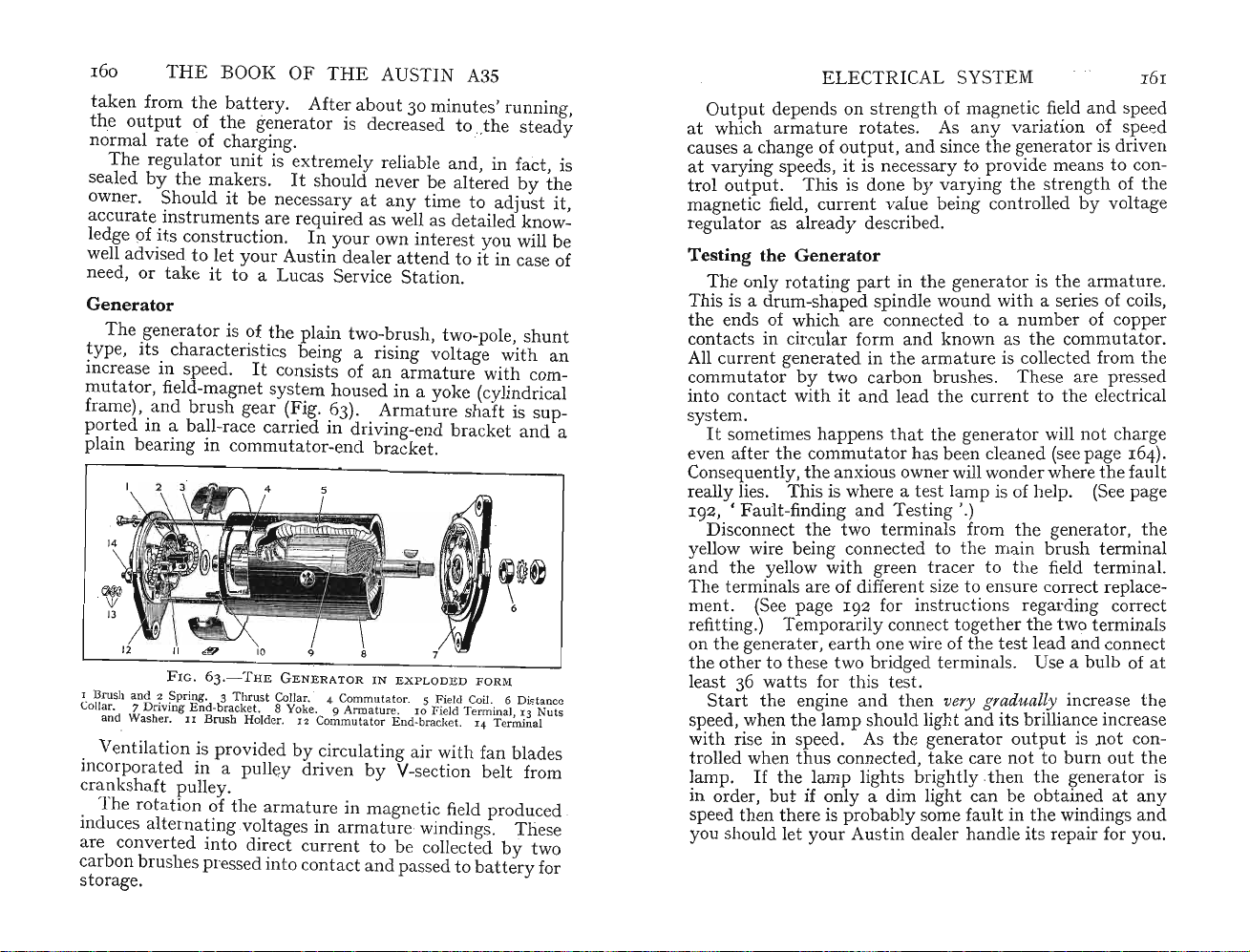
160
tak
theoutput
normal
Th
sealed
owner. Should it be necessaryatanytime to
THE
en from
rate
e regul
bythe
BOOK OF
the
batter
of
the
generator is decreased to ..the s
of charging.
ator
unit
mak
ers.
THE
AUSTIN A3S
y. After ab
out30minut
es' running,
tea
is extremely reliable and, in fact, is
It
should never be altered by
adjust
accurate instruments are required as well as detailed knowledge of its construction.
adv
well
need, or
ised to let your Austin dealer
takeitto a Lucas Service Station.
In
your own
int
erest you will be
att
end to it in case of
Generator
The gen
type, its characteristics being a rising vo
increase in speed.
mut
frame), and
p
ort
plain bearing in commu
1. Brush aud 2 Spring. 3 Thr ust Collar.' 4 Com
Collar. 7 Driving
and Washer.
erator
is of
the
plain two-brush, two-pole, shunt
It
ator
, field-magnet system housed in a yoke (cylindrical
bru
sh gear (Fig. 63). Armature shaft is sup-
consists of an armature with com-
ltag
e with an
ed in a ball-race carri ed in driving-endbracket and a
ta
tor-endbracket.
F IG. 6 3 ·- THEG E N E RATOR I N
End
-bracket. 8 Yoke. 9 Arm
II
B
rush
Holder.12Co
mmutatorEud-bra
EXPLODE
mutat
or. 5 Field Coil. 6 Di
atur
e. 1 0 Field Te
cket. 1 4 Terminal
D F ORM
rmina
stanc
l, 1 3 Nu ts
Ventilation is provided by circulating air with fan blades
incorpora ted in a pulley driven by
V-section belt from
crankshaft pulley.
the
arm
atur
The rotatio n of
induces alternating voltages in armature·windings.
are conv
carbon
ertedinto
bru
shespressed into contact and passed to
direct c
e in magnetic field produced
urr
ent to be collected by two
batt
Th
ery
storage.
the
ese
for
dy
it,
ELECTRICAL SYSTEM
Out
put
at
depends on strength of magnetic.
which armature
rot
ates. As any variation of speed
causes a change of output ,
at
varying speeds, it is neces
trol
output
. This is done byvarying the strength ofthe
magnetic field, curr
ent
fi
~ld
and
sincethe generator is driven
sar
y toprovide means to con-
value being controlled by voltage
161
and speed
regulator as already described.
Testing the Generator
Th
e only rotating p
This is a drum-shaped spindle wound WIth a
the
ends of which are connected to a
contacts in circular form
All current generated in
commutator
by
into contact with it
artinthe
and
th
two carbon
and
leadthe current tothe electncal
generat?risthe.
sen
numb
er of copper
known asthe commutator.
e arm
atur
e is collected fromthe
bru
shes. These are
armatu:e.
es of coils,
pres~ed
system. .
It
sometimes
even aft er
Consequently,the anxious owner will
happ
ensthat
the
commutator has been cleaned (see page
the
generator WIll not charge
~ond
er
164).
wherethe fault
really lies. This is where a test lamp ISof help. (See page
192,
• Fault-finding and Testing '.)
th
Disconnect
e two terminals fromthe generator,
yellow wire being connected tothe main
andthe yellow with green
tra
cer tothe field termmal.
bru
sh tem:inal
the
The terminals are of different size to ensure correct replace-
1
92
for in
stru
ment. (See page
refi
ttin
g.) Temporarily connect togetherthe two termmals
th
e generater, earth one wire of the test lead
on
the
oth
er to these two bridged terminals. Use a bulb of at
tts
e
least 36 wa
Startthe engine andthen very gradually increasethe
speed, when
for this test.
th
e l
amp
should light
with rise in speed. As the gener
trolled when
lamp.
in order,
thu
s connected,
If
th
e lamp lights bri
but
if only a dim light can be obtained at
ctions regarding
and
its
atoroutp
take
care
nottoburn
ghtl
y _thenthe
brillia~c
ut IS
speedthenthere is probably some fault inthe windings
c
o~ect
and
connect
e
increase
not
con-
out
~enerator
the
is
any
and
you should let your Austin dealer handle its repair for you.
Page 86

162
THE BOOK OF THE AUSTIN A3S
Maintenance
It
has already been
in
the
gen
ings.
Works
eratoristhe
Th
e front bearing is packed with grease
and
requires no furth er attention.
is a porous bronze bush.
this bearing consists of a felt
bushbya light spring.
'the
centre, is a small hole
engine oil should be ins
over-oil, however, for excess lubricant
the
commutator
gener
ator
If
gen
erator
causingthe
may fail to charge (Fig. 96).
refuses to
ignition warning l
th
with
remove
e commut
th
e generator
Disconnect one terminal of
th
connect
outofth
Loosen
e generator terminal connectorsbypulling
e loc
ati
ons in which
the
thr
ee bolts holding
and tothe adjusting link to allow
be released.
generator
away
Th
from
Fully unscrew thetwo bolts passing through
body;
whenthese have been
end-plate can be detached.
bring with it
Tak
e care
armature
the
end-plate.
The
the
not
to losethe distance-washers fitted on
shaft between
commutator
statedthat
armature
that
the
only moving
rotates
part
on two bear-
at
The
bearing in
miles. Do
find
ck,
and
ault
indicated
e f
and
rear bearing
its
way
then
ault
may
then
into
amp
remaining , on
ator
and
and
The
lubricator provided for
pad
pressed into contact with
At
the
rearofthe
which a few drops of S.A.E.30
erted
every
6,000
may
brush
es to
sti
cut
in-:-a f
'-th
bru
shes.
It
will be necessary to
partly
dismantle it .
the
battery
them
they
area
push
the
generator to its
the
en, remove all three bolts
the
engine.
withdrawnthe
Wh
en -it is removed it will
fit.
bracket
fan-belt tension to
and
lift
the
generator
commutator
two brushes in their mounting brackets.
the
commutator
surface should be bright .
and
the
If
it is not,
bush in
the
the
not
the
by
dis-
the
the
it should be cleaned. Before doing so it is as well to see
the
two brushes are quite free in their holders, for if
if
stick
the
commutator
that
takes place.
the
Test
brushes by gently pulling
fitted on each.
against
return
the
spring tension
(Fig. 64).
of their holders using a piece of
begins to '
burn'
the
It
should be possible to pull
and
on releasing
If
th
ey feel stiff, draw
bent
wire in
due to
the
flexible connectors
them
they
them
carefully
the
sparking
them
back
should
form of a
they
out
to
be
ELECTRICAL SYSTEM
the
hook to hold
spring clear of
a petrol-damped cloth.
If
the
commutatorisdirtyitmay
paper. Do not use emery cloth.
all
dirt
has
When
are
the
same
commutator
their
holders
way
and
they
been removed refit
round as originally.
if replaced half a
will not make effici
distance has been covered.
F
IG.64.-GENERATOR
Temporarily raise
oth
erwise
they
plate is refitted.
veniently for
the
may
the
purpose by engaging
brushes sufficiently in their holders
foul
the
The
brushes
sides. .
that
any
After ensuring
arm
ature
shaft so
shaft are in place, enter
that
line. As
diameter,
When
the
the
generator mounting-bracket holes are in
the
two through-bolt holes are drilled on
the
end-plate could be refitted half a
commutator
washers originally fitted on
has entered between
the
brush. Wipe
be cleaned with glass
the
brushes so
They'
bed
turn
round relative to
ent
contact
BRUSH
GEAR
commutator when
may
be wedged most con-
the
springs with their
the
end-plate on to
them
with
they
in'tothe
until
some
the
end-
turn
the
the
the
the
out.
two
Page 87

THE
BOOK OF
brushes fit
ma
nner, push
the
two bolts.
Reassemble
install
the
springs on
the
end-plate right home
the
generator to
th
e fan-belt overthe pulley
before finally tightening
the
Replace
batt
ery cable connection.
The
generator should now charge
If
there are signs
two terminal connectors
that
THE
AUS
TIN
A3S
top
of each brush inthe normal
the
th
e bracket-mounting bolts.
and
secure it with
enginetaking care to
and
to adjust its tension
and
sati
the comm
sfactorily.
utato
r is blackened a
refit
the
nd
despite cleaning, as described above, still will not charge
is best to
Battery
The
any
nected tog
rz-volt unit. Each cell contains positive
haveitchecked
batt
ery, one of
the
by
most
your A
ust
important
in dealer.
components on
car, is composed of six cells each of 2 vo
eth
er by lead
str
aps sothat
it builds up into a
ltsand
and
con-
negative
plates immersed in a solution of sulphuric acid and distilled
water known as
e electrolyte.
The
plat
es are divided
th
by insulator separators (Fig. 65).
ELECTR
Shouldthe
that
the
posts are of differ
.
It
is slightly larger
batt
ery be removed at
terminals are correctly reconnected.
ent
will be found
thanth
connection on replacement. A
connecting
The
re is a
the
positive cable to
tend
probably because •
The
prime neces
ICAL SYSTEM 16
any
time it is
importa
The
.sizes and are usually marked + a
that
the positive
e negative, to
battery
ency to neglect
it
must be all right for it is
sity
is to add distilled wa
post
pre
(the former)
vent any incorrect
can be ruined
the
negative terminal.
batt
ery maintenance
tertothe
working'
term
ina
nd
by
six
5
nt
l
.
it
FIG.
I Specific
66.-TES
Gra
TI NG
vity Reading. 2 See thatFloat is clear of
SPECIFICGR
Tube
AVITY
FIG.
65.-LUCAS
12-VOLTBATTER
cells
atleast
used for • topping
every month.
up'
for it contains iron
Tap
water should not be
andcertain
detrimental salts . A supply of distilled water sufficient for
r's
att
a yea
the
refore do
uyabott
B
station
ention can be
not
be t
le of distilled water from your chemist or service
and
keep it inthe garage for regular use.
obta
empt
ined for a shilling or two,
ed to ruin an expensive
battery
.
A useful accessory is a hydrometer specially calibrated
for car-battery use
stockist (Fig. 66).
to the individual ce
cell
tops-and
Y
electrolyte is correct.
and
obtainable
It
serves two purpo ses
lls-s
o preventing spilling liquid on
to ascertain if
throu
gh your usual
-to
the
specific gravi ty of
add water
the
the
Page 88

THE
I66
Consider first
Never allow
BOOK OF T
th
e question of liquid on
th
e tops of
the
sulphuric acid in the electrolyte will
quently, if
corrode
and
the
the
battery
batt
ery
The normal specific
I
'z80
approximately
thegravity
can fall to
to I
HE
AUSTIN
cells to be wet. Rememb er
att
A3S
topofth
e cells.
that
ack metal. Conse-
is over-filledthe terminals will
tray
will be eaten away .
gravity
'300
I'I
of a charged
batt
butas it becomes discharged
OO, when it is
pract
ically , flat
ery is
out '.
the
Checking
cap, ins
into
th
e glass
ert
bulb. Allow
but
make sure it is clear ofthe sides ofthe glass tube.
Then note
th
e specific gravity reading.
th
e reading of each cell is approximately eq
gravityisnot
the
hydrometer and draw some of
tub
e by compressing
th
e floatto be freely suspended (z, Fig. 66)
th
e figurethat
difficult. Unscrewthe filler
the
electrolyte
and
releasingthe
is level
It
is
withthe li
imp
ort
ant
quid;
to ensurethat
ual;
rubb
this is
also
thatthe level in each cell is the same.
If
one cell has a lower readingthan the
corrected by drawing off as
adding sulphuric acid of I '
corrected
by
several such additions it may be thatthere
is a short-circuit and
350
thebattery
much
s.g.
should be tested by your
oth
ers, it can be
fluid as possible
If
the cell ca
nnot
and
Austin dealer or local Lucas service station.
Similarly, if one cell appears to require topping up mor e
frequently
case for it may be
any ofthe others, examinethe b
thatthere is a crack
throu
gh which the
att
than
electrolyte is leaking away.
maint
The routine
enance required is given below
there is another pointthat should be mentioned. This is
the
batt
ery is
not
to make sure
in its container. Do not overtigh
allowed to become loose
tenthe securing clamps,
however, for the case may be cracked by so doing. On
other hand, if it is not sufficie
and
chafe
and
possibly damage the cable insulation.
Maintenance
Unscrewthe cell plugs monthly
l
yt
e level. Top up if necessary, as instructed above.
N ever hold a lighted match over the cell tops to ascerta
the level. The gases given off by a charged
flammable
and
can exp
ntly
tightthe case may move
and
examinethe electro-
batte
lode-
in some cases they have
ry are in-
er
be
ery
but
the
in
ELECTRI
the
blown out
tunat
e person who received
cell
have no inspection lamp use a torch, although
is very accessibly
The
electrolyte should be level
separators. Do
mount
not
CAL SYSTEM
topsand
ed ben
be temp
caused in
the
eath
ted
jur
y to
acid in his face.
the
with
bonnet .
the
top edge of the
to ' save topping up ne
the
unfor-
If
thebatt
you
ery
xt
month' by putting in too much distilled water for when
thebattery
filled the surplus will find its way i
ment, rusting
Never
, gasses '
add
the
level rises.
and
corroding everything it touches. , ,
anything
but
distilled water unless It
nto
If
the
the b
att
cells are over-
ery co
mpar
necessary to correctthe gravity, by adding acid as described
above.
comes more concentr
addition of distilled
strengthen
h
arm
no liquid is visible. In this case,
int
ex
thepast
dislodged unless covered with ac
actuallyimmersed in acid iscapable of,being charged.
if
becomes doubled,
protected from corrosion wi
If
and the insides of the terminal clamps. Securely tig
With
normal gassing the electro
the
ful to
theplat
When checking
ervals for it
tentthat
Partlydry
causes a gr
cells become damaged for two reasons : (a)
atedbut
wat
acid solution
is restored to normal by
er. Adding acid will progressively
and
es.
the
level in
may
be thatthe carISbemg used to an
eat
er-
the
cells you may find
insp~ct
than-
usual electrolyte loss.
lyte
becomes increasingly
at.more frequent
e of whichthe plates are formed tends to become
id;
and
(b) only
the
cell is half
Keep
the
necessary, disconnect
empty
and
the
chargmg
rat
e automatically
this is not good for the plates.
positive and negative terminals clean and
th
a film of petroleum jelly.
the
ter
minals, andclean
merely be-
the
that
th
e a
rea
!h
us,
the
.posts
ht
en
the bolts after replacement. As a very heavy current is
tak
en bythe starter motor,
ra
ting efficiently. Seethat the earthconnection f
ope
th
e positive terminals to the chassis is clean and that the
olt
is tight. .
b
Owners sometimes wonder if frost can damage
batteri
es should
fully-charged ba
gr
avity
will not be affected
cases where
tt
thebatt
the
electrolyte freeze.
ery
with
ery isfully- or nearlyfully- discharged
dirt
y terminals prev
electro
lyte
by
the
severest frost.
ent
rom
the
In
England, a
of the correct
In
and where the frost is severe, it is possible for the
t-
IS
it
ir
Page 89

168
electro
Wit h the electrical system on your Austin A35 the
in normal use should be k
cha
ba
becomes'sulphated'and
hold its charge.
Austin dealer
given a
THE
BOOK OF
lyte
to freeze. This usually means a split container.
rged
by
the
compens
Should your car be
tte
ry will rapidly deteriorate if left discharged.
out
THE
AU
ept
efficien
tly
atin
g voltage system .
of use for
any
STIN
A3S
and a
utom
len
gthoftime,th
in extreme conditions will not
It
is good policy,therefore, to let your
have
your
batte
ry,
arra
month
ly charge. This will keep it in good con-
nging for it to be
batter
atically
dition until you require it again.
Ignition
The ignition coil is a sealed self-contained
no
from keeping
System:
att
ention forthere are no moving pa
Coil and Distributor
the
terminals
tight
unit
rts
and
in it.
the insulated end
requiring
Apart
clean, you can forget it completely.
th
By a process known as induction,
up the primary 12 volt s supplied
imately 12,000 volts. This high-tension
th
e s
park
ing-plug gap ofthe correct cylinder to which it
by
is supplied
the rotor of
the
e ignition coil steps
bythe
battery
current, jumps
distributor.
to approx-
Any electrical breakdown in the ignition coil is extremely
ept
unlikely provided it is k
The contact-breaker in
points, when a high-tension current is gene
secondary coil. This causes a
points and
and compressed in,
driven from
thisspa
th
e engine
rk fires the charge already drawn into,
th
e cylinder.
when each piston is at
On
th
e distribu
tor
cap, which is
material, are five high-tension cables
par
ach s
ontact inside
all d
connected to
king plug and a centre cable w
the
cap and resting on an insulated arm
the'rotor'.The
the
coil. Insidethe cap are four me
clean as described above.
th
e distr
ibu
tor
opensthe contact
spark
to occuratthe
Th
andistim
the
topofth
e con
ed for
the
e compression stroke.
mad
e of an insulat ing
-one
ith
oth
er end of
thi
ratedinth
plug
tact-
breaker is
spark to occur
connected to
a carbon
bru
s fifth cable is
tal
con-
tacts to each of which a high-tension cable is connected.
mount
The rotor is
ed on the distri
so that its outer end passes
th
but
or shaft
e four high-tension
andturn
conta
with very little clearance.
th
en, is
The electrical-circuit operation,
thatthe contact-
sh
cts
ELECT
br
eaker poi
th
y
e
It
e high-tension.curr
it
is genera
dis
tr
through
metal strip across which the currentis led to th e appropriate
nts
ted
ibutor cap.
the
carbon brush resting on it.
open at a predetermined in
along
RICAL SYSTEM
stantproducing
ent.Th
the
is is led from
cable to
the
cen
tre
the
contact inthe
Fromthis point it passes tothe rotor
Th
e rotor has a
16
coil where
9
contact. This contact is connected by a high-tension cable
~oth~
sparking plug of theparticular cylinder then due to
fire .
The
high-tension brush at the ce
special type, in
This eliminates wireless
should be noticed
fitted in
necessity to fit an
distrib
utor
suppressor
could be fitted. However,
suppressor at the
thata suppression resistor effect is provided.
and
that
thecent
is of an early
at
the
brush location,
there is no external suppressor
re H.T. lead
ext
ernal
suppr
type
the
brushand
pressor might result in difficult s
Th
e mechanism ofthe distrib
ntre
of the cap is of a
television interference.
and
there should be no
essor inthe lead.
and
does not incorpor
then
an external suppresso r
If
ate
combination ofthe existing
an additional
tarting
utor
ext
ernal sup-
or misfiring.
is quite simple
and
It
the
a
incorporates two devices for varyingthe time at which
th
e con
tact
consist of one known as
tact,theother
con
end
e
and
points are to be separated. The contact points
the
'fi
xed'
or ' a
dju
linked to a spring
mounted on an
that
arm
insulated on one
presses it against
the
sta
ble '
fixed
contact (Fig. 67).
A small fibre tongue is provided on the moving contact
nte
d on
the
'ti
rel
ati
the
ntr
e '. This
distri-
ming '
ve to
position
oth
the
er
so that as the four lobes of a cam mou
butor
shaft rotate it is successively separated fromthe
fixed co
correspondingly a spark at
(i.e.
th
of the piston when it has reached
upw
s
direction being known as
tim
slowly
3,500 r.p.m. unless there is a means of ' a
ntact
. This produces the high-tension currentand
the
Th
e reason forthe necess
th
e period ofthe occurrence of the s
e pistontravel) is
Assume the s
ardtrav
el-t
not
park
occurs at top dead cent
he corresponding position inthe
plug points.
ity
of alteringthe
park
always understood.
re-
th
e extreme limit of its
'bottom
dead ce
ing will be satisfactory when th e engine is running
but
since the engine speed can increase up to say
dvancing'
Page 90

THE
0
17
A Cont act P oints. B Condenser. C Contac t Adjusting Screws. D Micrometer
BOOK
FIG. 67.
Adjnster. E . Cam and
timing,the piston would be so far down its
the greater r.p.m.
OF
-DI
STRIB
thatmu
THE
B
UTOR
TY
Driv
e-shaf t Oiling Point
AUSTIN
PE
D
c
MzP
H4
A3S
D
strok
e at
ch power would be lost before
the mixture has fully ignited. Accordingly, an ingenious
device, known as
incorporated so th
spark au
toma
fact, with the engine running f
siderably before
Owing to
the
th
e c
entr
at
ifugal
with increase in engine speed
tically is made t o oc
astthe sp
th
e pistons have
limited
tim
e available, however,
rea
adva
nce mechanism, is
cur
earlier.
ark
ched
top
dead c
the
the
In
actual
occurs con-
entr
mixture
is
not
-fully ignited
work until
ELECTRICAL
and
the
pistons
therefore is
just
SYSTEM
notready
to do useful
commence to descend,
171
thus
ensuring efficient operation.
The
adv
weights normally held inw
they tend to fly
linking
to its driving shaft and
At first sight
so anxious are
operation
ance mechanism consists of two spring-loaded
ard
s. As engine speed increases
th
em to
outwardsand
the
distributor sh
th
is arrangement would ap
the
designers to
advan
this
tend
ency is utilized by
aftsothatit
ces
the
ignition.
obt
ain
thorou
turns
pea
r ideal.
ghly efficient
thatthey have incorporated a vacuum
relative
But
timi
ng
control. Under conditions of sudden acceleration from
rel
ativ
ely slow engine speeds
the ignition suddenly to advance due to
depression in
th
e manifold. The va
working off this depression, controls
advancement in relation to
theremay
the
throttle
be a tendency for
th
cuum
th
e change of
tim
ing control,
e speed of ignition
opening until
the
depression is constant. Directlythe engine speed has
risen sufficiently,
the
timing con
tro
l providesthe correct
range of advance .
There is one other imp
bu
tor
known asthe c
unit
having no mov ing
in parallel with
thecontact
that otherwise would occur
Maintenance
As
with
regular lubric
and
Ev
aside
Apply two or
the
all other mechanisms, the di
at
ion.
the
slight
att
ery
1,000
th
e two r
headofth
ent
miles remove
eta
thr
ee drops of
e screw inside
ort
ant
ond
enser
part
component inthe distri-
but
this is a self-contained
s.
It
is ele
ctr
ically connected
points and reduces
and
could soon burnth
any
spa
e points.
stributor
It
is provided w
ith
suitable lubricators
ion req uired is easily carried out.
the
ining clips. Take off
distributor cap,byspringing
the
thin
machine oil adjacent to
the
mounting carrying
rotor arm.
rking
requires
the
rotor. A small passage is provided to conductthe lubricanttoth
lobes with a film of petroleum jelly. .Do
excess
engine is running
or grease on
e.
cause erratic running or even complete failure.
Since
e surfaces needing it (Fig. 68). Smearthe cam
not
oth
erwise it will be flung off
and
may
reach
the
cont
act
points is detrim
the
spark
has
to be delivered to
the
the
contact
the
apply an
cam whenthe
points. Oil
enta
l and
correct cylinder,
may
Page 91

172
when replacing the ro
THE
BOOK OF
tor
THE
note
AUSTIN A35
tha
t there is a regis
ter
to
ensure.it is replaced correctly. Due to its specially-designed
shape the cap cannot be replaced incorrectly.
Lubricate the spindle on which
is mounted. The contact-breaker
FIG.
68.
A Connection from Coil to Contact-breaker. BB Points
Adjustment Screws. C Condenser. D Contact-breaker
Points. E Micrometer Adjuster. F Vacuum Pipe Union
-0ILING
allow grease to be applied
the
moving contact arm
arm
must be raised to
DISTRIBUTOR
but
do not finger the contact
point or allow grease to reach it. ,
The moving contact
the nut holding the low-tension cable to the
Loosen n
spring may
ut
adjacent to insulated collar
then
When replacing
insert th e slo
tted
end of the bolt and the insulator.
check
that
the
spring
The flat insu
the pivot must
lated
not
may
be freed by first unscre:ving
and
slotted end of
be detached from bolt.
the
lightly greased contact on its pivot,
end of the spring between
Tighten
and
contact are correctly aligned.
washer fitted beneath
the
the
thecontact
be omitted.
termina
squared.
nut and
on
The distributor mechanism should be lubricated. Access
is obtained through a small hole drilled in the base. Lubricate sparingly,
but
avoid excess oiling.
Replacing the Plug Leads
If
the plug leads are removedatany time,
and
if they
ELECTRICAL SYSTEM 173
are
not
proceed
that nearest the radia
and turn the engine by the starting
air blowing
is rising on
numbered or marked to ensure correct replacement,
as.
follows: ,.
the
Unscrew
sparking plug from No. I cylinder (i.e.
tor
). Press
past
your thumb. This shows
the
compression stroke.
the
thumb
hand
over the hole
le until you feel
that
the piston
Another method of ascertaining approximately top dead
centre
position on No. I cylinder compression stroke, is to
remove the valve-chamber cover. Move the engine nearly
half a
valve for No.
stiff piece of wire in the sparking-plug hole
turn
topofthe
turn
after the inlet valve has closed. The inlet
To establish
I cylinder is No
the
exact position of
.2
from the front.
the
piston, insert a
the engine. The wire, suitably bent to rest on
piston, will indicate when
the
piston is at its
and
slowly
the
topmost position.
With
the
on top dead centre firing position on No.
engine set by either method, approximately
I cylinder, proceed
as follows.
Remove
contact /the rotor
cap, noting
plug leadconnecting No.
Follow aro
the
distribu
the
und
the distributor cap in an anti-clockwise
tor
cap
and
ascertain to which
arm
is pointing. Replace the distributor
terminal socket concerned. Insert the
I cylinder to this terminal socket.
direction, looking down on top of the cover, and insert
the plug lead for No. 3 cylinder. Next to this, again
l.
moving in an anti-clockwise direction, fit
the
Lastly, fit
turns
in an
the firing order isI,3, 4
If
th~
th
e engine so
stroke. (The method of doing
lead to No. 2 cylinder. Since the rotor
anti
-clockwise direction it will be realized
distributor has been
that
No. I cyhnder IS on the compression
and
2.
:emov~d,
th
is is describedatthe
NO.4plug lead.
that
re-time by turning
top
of previous page.)
Next, check
that
the
contact-point gap is correct.
If
not, reset as described above.
Wit~
the
the points should Just be about to open.
rotorJ?ointing towards No. I cylinder contact,
loosen the clamp bolt, which is on
s
tarter
motor, so that the distribu
tor
If
this is
not
so
the
same side as
th
body can beturned to
e
obtain this setting. Lock theclamp bolt securely when set.
Page 92

174
cap should be
and
weather is wet.
to
the
THE
BOOK
The
out
side, as well as
dirt
can
cause short-circuits particularly w
earth
without
same reason, wipe
OF
THE
AUSTIN A3S
the
kept
clean. An accumulation of dust
The
high-tension current
causing sparkingatth
the
leads as well asthe plug insulators.
inside, of the dis
the
e plug points.
tributor
hen.the
n leaks away
For
Adjustments .t
Check
the
Th
contact-breaker gap ev
is is quite simply donebyremovingthe distributor
ery
5,000 miles. .
c
~p
and turningthe enginewith thestarting handleuntilany one
the
of
points.
lobes of
The
'406 mm.),
gauge provided in .
Carefully inserted,
the
gap.
ead
just
r
When
by
the
moved nearer to or away from the
adjustment
tightened,
Modificat
On l
ater
the
cam has fully separated
the
gap, which should be '014 to '016 in. ('356 to
may
be checked by usingthe appropriate feeler
the
tool
kit
the
gauge should exactlyslide between
If
the
gap is too wide- or if it is too narrow-
looseningthe two screws in
se are loosened,the adjus
has become altered when
recheck
ion
mod
and
correct if necessary.
to Distributor
els a modified di
.
tab
stributor
the
ontact
er.
In
the
screws were
base plate.
case
le c
oth
is fitted (Fig. 69).
contact
may be
the
ELECTRICAL
To adjust contact-breaker po
contacts are fully open.
Then
screwdriver in slot (2). Move
SYSTEM
intsturn
engine over until
slacken screw (1)
plateuntil
gap between
and
ins
175
ert
contacts is '014 to '016 in. ('356 to '406 mm.) . When
It
tighten
may
setting is correct,
Th
e contact-breaker points should be cleaned every
6,000 miles.
or have worn un equa
o
ther
a corresponding hollow.
locking screw
be found
lly-usua
and
re-check
that
they
have
become d
lly one develops a peak;
The
most satisfactory way
gap
irty
the
to correct this unevenness is to remove the contacts,
th
ed on
If
base.
terminal n
-the
Take
the
required,
loosening bo
con
tact
spring. The spring
fromthe bolt
off its pivot.
washer fi
the
by
from
tt
base.
unscrewing its two adj acent screws
the
uts
on
the
bolt
may
then
end is slotted-
care
pivot
not
betweenthe moving contact and
the
other cont
and
to lose the flat insulated
that
be disconnec
the
contact drawn
act
can
and
lifting it away
holds
the
ted
be removed
To restore the points to their original condition use either
the
a fine carborundum stone (Fig. 70) or one of
special
s.
FIG
. 6 9.-D I ST RIBU T OR AS
I Control AdjustingScrew and 2 Slot. 3 Cam and Drive
Oiling Points. 4 Contact Points. 5 Micrometer Adju
FITTED
TO LA
TER
4
MODELS
Shaft
stment
FIG.7o.-TRIMMING
-UP
CONTACT
POINTS
Page 93

THE
may
may
BOOK OF
be
176
files
that
emery cloth
grease after facing
dead flat and
possible from
true
the
obtain
also be used . Clean away
thepoints,th
with
points. Replace and readjust.
TH
E AU
STIN
A3S
ed forthe purpose. Very fine
any
e aim being to leave
one
anoth
er. Remove
the
minimum
grit or
them
Ignition Timing for GradesofPetrol
To
obtain
t.d. c. on its compression
ing '. This position is indi
Fig. 71) corresponds with groove in
FIG. 7I.-IGNITIONTIMINGMAR
(Left ) Early
are in line. (Rig ht) Igniti on timing
small pointers indica te SO and
Then, r
with
SOpointer. This is of ass
amount of ad vance for commercial
ett
ing being 6° before t.d.c.
s
correct ignition timing, set No. 1 pi
strok
e, with valves 3 and 4 •rock-
cat
ed whenthe 0° pointer (Right,
crank
shaft pulley.
typ
e of igni
adjusting
otati
timing
ng crankshaft backwardsbring groove into line
PULLEY
tion
mark
ing indi
mar
10
° before TD C. Th ey are of assista nce in
when using premium grade petrol
KS ONCRANKS
catin
g TD C when hole and
ks on E ngines
ista
aft
er No.
9
3~36
nce when setting correct
typ
e fuel,the advised
ston
HAFT
arro
.
Th e
w
Withpremium grade fuels follow the same procedure
except
thatcrankshaft,
compression stroke of
untilthe groove in crankshaft pulley corresponds
aft
er being positionedatt.d.c. on
NO
. 1 cylinder, is
rotatedba
ckwards
withthe
10° pointer (Fig. 71). This assists when setting correct
ELECTRICAL SYSTEM
amount of ignition
setting
being 12° before t.d. c. Asthere will
pinking to serve as a warning when
is most
important
Now, remove di
clamping
plate.With
NO.1 electrode in di
at
tactbreaker points begin to open. This inst
determined exactly
circuit. Hold one lead to
terminal.
opens and
Fin
The
the
ally, tighten pinch bolt, refit distributor cover
test car on
effected on
engine should pi
top
in
gear
violent, or continues after 30
ret
ard
ed. Conversely, ifthere is no pinking, or if it dies
adv
ance for premium fuels,the advised
pr
that
this
settin
stributor
stributor
with
cover
rotor
arm
cover, rotate casing
the
aid of a smallbulb in a b
earth
light will go
sparkisth
the
road. Any
th
e vernier adjusting screw (Fig. 67).
nk
slightly
with
accelerator pressed down.
outatth
en correctly
furth
und
emium fuelis used, it
g is
strictly
and
slacken pinch bolt in
pointing to position of
andthe other at condenser
e inst
antthat
tim
ed for all cylinders.
er adjustmentmay be
er loadat10 to 30 m.p.h.
m.p.h
., ignition should be
not
adh
antmay be
If
I77
be any
ered to.
until
con-
att
ery
gap
and
Th
pinking is
out
e
early, ignition should be advanced.
Road TestofIgnition Timing
Withthe
thus
increasing
to
retard
by turning
as required
gradu
the
the
ignition
the
knurled knob of
-clo
ckwise to
al format ion of carbon inthe engine,
compression, it may be found necessary
tim
ing slightly.
the
retard
Th
is may be done
micrometer adjustment
and
anti
-clockwise to
advance (E, Fig . 68 or S, Fig. 69).
To make a
timed
wat
pr
acceleration procedure. This will require a stop-
ch and someone to help you.
of
roadthat
eferably not downhill or this would affectthe char
road
test,the easiest m
ethod
is to use
Tak
e the car to a stretch
is de-restricted, free from sideturnings,
act
the
and
er-
istics of ignition advance.
run
Timed acceleration
takeninthe
road,and
in
top
same direction
under
gear at a speed
similar conditions. Have
s are necessary. All should be
and
overthe same
just
below 20 m.p.h.
str
the
car running
etch of
Thenthe
accelerator pedal should be pressed fully open and speedometer
carefully observed bythe helpful friend with the
stop-watch.
Directly
the
speedometer needle is on ' 20 ', the stop-
Page 94

TH
17
8
E BOOK OF
watch should be started.
mum
speed-i.e. 50 or 60
partofthe
On achieving
testthe accel
the
desired ma
speedometerstopthe stop-watch. Notethe
ac
curatel
y as possible. Goback and repeatthi
the ignition a
is less
thanprev
ignition
obt
ained.
until
dva
nced a little more.
iou
sly, continue te
no
impr
Obviou sly, ifthe ignition is
time
taken
it means
its ma
It
to accelerate betweenthe set fi
thatthe engine is over-
ximum
perform ance.
is not necessary to
Some drivers- particularly
THE
AU
STI
N A35
andstoppedat
m.p
.h. Underthe whole of
erator
must be fully open.
ximum
an agreed
speed reading on
s testwith
If
th
ovem
ent
in acceleration
furt
adva
tim
e up to speeds of 50 or 60 m.p.h.
tho
se who own a new car-
stingand
e recorded t ime
adva
ncingthe
her advanced but
gur
nced and is
es increases,
not
max
this
the
time
time
the
giving
may
wish to restrict road speeds. Accordingly, acceleration
times may be taken between 20
thi
s will comm
limits.
te
stin
g between 20 and 30
tim
es mustbe taken with g
uptosay
ately affectthe re
end
Theimportant
itself withinareas restricted
point
60 m .p.h. an error of a second will notproportion-
sult
so much asitwould do when te
up to 30 m.p.h. whereitcould represent a large
ofthe
time
by
this
it will
involved.
methodthe car is set to
run
equally well on a premium-grade fuel,
thebett
Th
e moral is, of course, to reset
If
then
the
additional benefit
will not be obtained.
ignition sothatthe premium-grade fuel
tothe
grade fuel,
th
should be reset or some
best
Co
nve
adv
rsely, if
but
e engine will
anta
ge.
the
car has been set to use apremium-
a sta
ndardgrade
prob
ably be r
what
and30m.p.h
to obs
m.p
.h.,
rea
t accur acy. When te
er-
erv
e isthat
the'
stop '
run
on standard fuel
grad
e fuel can confer
may
fuel is constantly used,
ath
er over
har
sh and possibly inefficient
-adv
. No doubt
by
speed
when
and'sta
rt '
sting
stin
proporti
but
the
be utilized
anced
and
performance will result.
Sparking Plugs
Although an insignifi
in
gplu
g is mostimportant.Plugshave
high
temperatures, must be of
cant
accessory to look at, the spark-
to operate
suitabl
e reach for
the
under
plug
as
on
ELECTRI
i-
points to be inthe bestposition for igni
and mustnot
be so cool as to pe
CAL SYSTEM
rmit
oil to collect onthem
tin
g the mixture,
179
or so hot as to causepre-ignition. Obviously,the corre ct
ty
pe of plug is neces
use
the
typ
e rec
omm
sary
and you will be well advised to
end
ed by
the
Austin Motor Co.
Ltd.
This isthe Champion N5. long-reach typ e.
No
plu
g has an
par
is
ticularly whenitis not a
ad
vised to consider renewing plugsthat
10,000 miles. Often erratic
ind
efinite life
and
on an efficient engine,
lar
ge one, the owner is well
have exceeded
runn
ing and bad
sta
rtin
g can
betraced to plugs,the useful life of which has been exceeded.
Periodically removethe plugs at least every6,000 miles
and cleanthe points of
a type of
ha
ve to be clean ed
brushkno
by washingthem out t horoughly in petrol.
not
resp
ond
to thistre
th
em for you on his sand-blast . This will only cost you .
a few pence
and
a r
and
the po
eport
given ontheir condition.
Rememb erthataplu
by over-tightening or by acci
Fin
g
ally, do notbe tempted to use plugs without their
gaskets .
compression be
thatthe mi
You
cannot get a perfect seal and not only will
lost
xtu
re will be upset onthe in
anycarbonby
wn as a ' file car
int
ernally, this is most easily done
atm
ent
let yourAustin dealer clean
int
s can be set, tested
g is vulne
denta
but
alsothere will be
bru
shingthem with
d'.
Should the plugs
und
rab
le and can be damaged
lly
hittingthe
an
duct
ion stroke.
If
th
ey do
er pressure,
insulator.
air leak so
Plug Adjustment
Having cleanedthe plugs, testthe gapatth
Th
e gap should be '025 in. (,64 mm.) (A, Fig. 72).The plug
gap is
very
imp
ort
ant
and
any widevariation as between
th
e f
our
imp
electrode.
fitted to
by
plugs onthe engine can make even slow
ossible.
If
it
is necessary to a
If
the gap mustbe a
the
plu
djustthe gap, never b
dju
sted, b
g body. Many plugs
endthe electrode
have
owners bendingthe centre electrode resulting in either
end
been
e points.
runnin
the centre
ruin
ed
g
loosening it inthe insulator or crackingthe insulator
In
either case
Alwa
tributor
moi
sture
ysk
the
plu
eep
g soon becomes
the
plng insulators,
the
cap free from dustand dirt.
can
collect on
thi
s film of dustmaking
fault
leads,
In
y.
and
damp
the disweather
starting
Page 95

180
difficult becausethe high-tension
circuit to
THE·BOOK
FIG
The gap at inset A Top left should be .025 in.
. 72.
OF
-ADJUSTI
THE
NG
AUSTIN
PLUG
current
earth
ratherthan
sparkatth
Tracing Ignition Troubles
If
the
ignition is carefully maintained, as describ ed in
the
preceding pages, you should
due to breakdown.
But
as
have
no unforeseen delays
any
complic
mechanism is liable to develop some sli
be well to consider
what
minor difficulties may arise
how to correctthem.
Ignition trouble usually falls
stoppage or
Suppose
intermitt
the
stops. The following
of finding where
Leaving
the
ent
car, otherwise runnin g perfectly, suddenly
test
th
e trouble lies.
ignition switched on, disconnectthe low-
und
er two heads:complete
firing.
should indicate the quickest way
GAP
tend
e plug
ght
A3S
s to short-
point
ated
defect it
s.
piece of
may
and
ELECTRICAL
ten
sion cableatthe
baremetal
of
should be seen.
thi
s wire there
deed, a broken wire
the
low-tension circuit generally by seeing if
side of
the
cylinder block
If
you
may
cannot
be a
thatwill have to be located. Test
SYSTEM
the
distributor. Touch
with
it, when sparks
get
any
dirty
or loose conn ection or, in-
sign of
current
the
lamps will light.
If
current is reachingthe low-tension feed, reconnect it
and
make surethe rocker
for
it
to stick
the
arm, clean
replace it.
if necessary. See
If
the
from
the
cylinder block.
separate
a spark from
spark
is forthcomingthen
If
a
spark
the
cap
engine
th
e cylind er block. Should no
then
there
but
it may
the
If
the
that
points are in order, disconnect
distribut
or cap
With
th
em by pressing
th
e high-tension cable to
is produced, refitthe cable to
and
test
the
and
holdingthem oneata
may
be a short-circuit in
arm
is free to move. It is rare
have
stuck
open.
If
so, remove
bush inside, lightly oil its pivot
arm
is free, check
the
points are clean
and
holditabout
the
points normally touching
them
the
coil is probablyatfault.
sparking-plug leads
spark
the
gap,
the
i in. from
apart.
This should cause
the
block.
the
by
timeabout
be visible from any,
the
rotor
and
centre wire
cap, replace
turning
1in. from
or distributor
cap.
Misfiring is
due to some condition such as
spring, stiff rocker
on
the
petrol
distributor cap or rotor, sticking valves, obstru
supply, or
A broken wire is
being
bound
obviously a
ends of
such a case, as
the
joint with insulation tape.
Additional causes are loose
dirty
and
not
togetherin
temporary
the
wire
maladjust
always easy to trace being generally
dirty
-arm
action, short-circuiting due to
carbur
ettor
misadjustment.
not
always easy to
the
looms.
repair
maybemade
and
the
twisting
system is an ' earth r
ed plugs. Normally
If
them
wires
contact
trace
found
points, weak
owing to m
and
by baring
togeth
er.
eturn'
and
connections or
the
accessible,
do
high-tension
cables, although well protected, might develop a
circuit if
should
Remove
the
not
insulation has perished. This possibility
be overlooked.
th
e plugs, clean
and
test as already suggested.
adju
flat.
But,
protect
181
the
on
head-
and
sting
the
If
no
the
dirt
cted
any
the
in
short-
Page 96
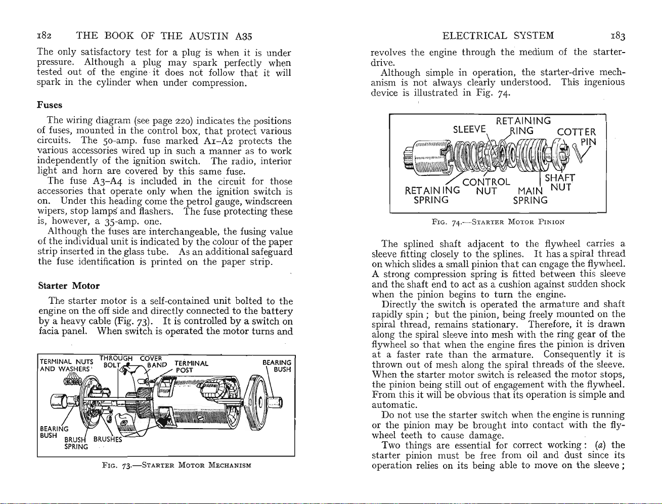
182
THE
BOOK OF
THE
AUSTIN
A3S
The only satisfactory test for a plug is when it is under
pressure. Although a plug
tested
spark in
Fuses
outofth
th
e engineit does
e cylinder when
spark
not
und
er compression.
perfectly when
follow
that
it will
may
The wiring diagram (see page 220) indicatesthe positions
of
fuses, mounted in the control box, thatprot
circuits. The 50-amp. fuse
various accessories wired
independently of the ignition swit ch.
ght
and h
orn
li
Th
e fuse A
accessories
on. Under
wipers, s
top
is, however, a 35-
are covered by
3-A4
th
at operate only whenthe ignition switch is
th
is included inthe circuit for those
is heading come the petrol gauge, windscreen
lamps and flashers.
amp
Although the fuses are
of
the
individual unit is indicatedbyth
strip inserted in
th
e glass
the fuse identification is
Starter Motor
markedA1-A
up
in such a
mann
The
thissame
The
fuse protectingthese
. one.
int
erchangeable, the fusing value
e colour of the paper
tub
e. As an additional safeguard
print
ed on
the
The starter motor is a self-contained
th
engine on
by
a heavy cable (Fig. 73).
facia panel.
e off side
Wh
FIG.73
and
dire
en switch is
.-STARTER
ctly
connected tothe
It
is controlledbya switch on
operatedthe
MOTOR
MECHANISM
unit
ect various
2 protectsthe
er as to work
radio, interior
fuse.
paper strip.
bolted tothe
batt
motor
turnsand
ery
ELE
CTRICAL SYSTEM
revolvesthe engine through
the
medium of
thestarter-
drive.
Although simple in oper
on, the
st
arter-
~riyem
~ch~
ati
anism is not always clearly understood. This mgemous
device is illu
strated in Fig. 74.
FIG.74
.- S TARTERMOTOR
PINIO
N
The splined shaft adjacent to the flywheel carries a
sleeve fitting closely to the splines.
on which slides a small pinion
th
It
has a spiral
thr
ead
at can engagethe flywheel.
A strong compression spring is fitt ed between this sleeve
ndthe shaft end to act as a cushion against sudden shock
a
turn
the
when the pinion begins to
Directly
rapidly
spiral
along
flywh
at a faster
thrown out of mesh along
When
th
e pinion being still out of engagement with
From
th
e switch is operatedthe
spin;
but
the
pinion, being freely
thr
ead, remains stationary. Therefore, it is drawn
the
spiral sleeve
eelso
the
starter
that
ratethanthe
when
motor
into
mesh with
the
engine firesthe pinion is driven
armatur
the
spiral
switch is released
this it will be obviousthat
engine.
armature
and
mountedonth
the
ring gear of
e. Consequ
thr
eads of the sleeve.
ently
the
motor stops,
the
flywheel.
its operation is simple
shaft
the
it is
and
automatic.
art
Do not use the st
the
or
wheel te
pinion
may
eth
to cause damage .
Two things are essential for correct working :
start
er pinion
must
operation relies on its being able to move on
er switch whenthe engine is running
be brou
ght
into c
be free from oil
ont
act withthe fly-
and
dust
since its
the
(a)
the
sleeve;
e
Page 97

184 T
(b
)
theba
m
otor
along
Starter Pinion
It
the
freeing it. One is to engage
HE
BOOK OF THE AUSTIN A3S
tterymust be sufficiently charged for the s
to operate quickly enough for the pinion to slide
the
sleeve into mesh withthe flywheel.
Jamming
sometimes happensthatthe pinion jams in mesh
flywheel. Should
thi
s oc
curthere are two ways of
top
gear
andthen rock
car backwards and forwards whenthe pinion
freed.
th
brake is released.
adopted ifthe first is
cap pressed over
On removing
end on which a spanner
maybeturn
of the shaft is anti-clockwise,
the
it
m
It
is imp
ortant
e ignition should be switched off
FIG.75.-TuRN
thisit
that, if this method is employed,
and
thatthe hand-
Th
e second
IN G S QU
FR
EE J
AMMEDSTARTER
not
successful, is to detachthe small
th
e rear
will be seen
may
meth
od, which may be
AREDEND OF S HAFT TO
starter-m
otor bearing housing.
that
the s
be fi
haf
tte
d and so
ed (Fig. 7S).
th
e normal direction of
As
pinion. Shouldthe sh
rotati
on ofthe squared end
turnin
g it clockwise
aft
continue to prove ob
may be necessary t o undo the bolts securing
otortoth
e engine
but
this is rarely required.
t has a squared
tar
may
the
may
stinat
thesta
ter
with
the
be
shaft
free
rter
ELECTRI
If
it is foundthatthe pinion fails to engage
known that
th
e battery is fully charged,thenthe starter
mot or should be removed and
in paraffin to obv
Th
ey must
not
iate
be oiled.
it is best to disconnect
CAL SYSTEM I8S
anditis
th
any
thebatt
e pinion and sleeve washed
tendency forthem to stick.
If
th
e sta rter
mot
or is removed
ery to avoid any possibility
of a short-circuit.
Th
e switch contacts are of large area
use should not require to be cleaned,
commu
which case
generator (see page
in the commutator are not
ta
tor may become
th
ey may be cleaned as in the case ofthe
162).
The bearings of the a
dirtyorthebru
It
should be noted thatthe slots
undercut
rma
ture shaft, being ofthe oil-less
and
with normal
butthe armature
shes stick, in
, as in the gener
ato
r.
type, do not require lubrication.
sta
ath
er, or if a
rter motor
und
The
th
e engine
we
results. Under cold s
will first free
and
switch
are
fully capable'of starting
er normal circumstances
thi
ck grade of oil is in use, heavy loading
ta
rting conditions
th
e engine by usingthe
but
the
startin
wise owner
in severe
g handle.
Such consideration will result in increased life so far as
the
ba
tte
ry is concerned.
Horn
Adjustment
Pr
ovided it is securely mounted the horn requires
a
tte
ntion. The wiring circuit is fed through a fuse and
should the horn fail the fuse should be inspected.
operation
be of help first to check
Using
current is reaching
pressed.
troubl
cleaned and
does not li
may
indicatethe need for ad just ment.
th
th
e test l
amp
th
If
thelamp
e is
inthe horn itself. The contacts should be
readju
sted as described below.
e horn switch.
(described on page 192) check if
e horn terminal whenthe
glows when
thus
tested, thenthe
ghtthere is a broken connectionatsome
If
littl
Err
ati
It
may
button
the lamp
point
e
c
is
inthe circuit.
T~eho
retainer
~n
switch is accessible by carefully prisingthe
ring out of
th
e centre ofthe steering-wheel hub,
when the contacts will be disclosed.
L
~ os.
e
e
but
instrume
J?ounting
If It ISfoundthatthe condition is associa
nt
itself means for
can
affectthe note emi
adju
stm
tte
ent
is provided.
d bythe
ted
withthe
horn
Page 98

186
wise it
be screwed down too far.
ofthe
or a short-circuit may result. Adjusting does
thepitchornot
of compens
body.Then
clockwise direction so
separated.
a little at a
not
the
together. Securely lock the setti ng withthe lo
THE
BOOK
It
is bestto remove th e fuse when
may
inadvert
OF
TH
ently
be blown should
Take
hom
from touching
the
e ofthe horn
atin
g for any wear
Fir
st loosenthe lo
cknutinth
turnthe adjustin g se
thatthe c
Thi
s can be checked by moving the adj ustment
tim
e until on pressingthe horn
sound.
Thenturn
the
adjusting screw six notches in
opposite direction, to bringthe
E AUSTIN A3S
adju
stin
g, for ot
the
adju
stment
care to keepthe terminals
chassis when disconn
not
butt
control
the
on it will
but
is provided as a means
that
may arise in use.
e centre rear of
rra
ted screw in an
ont
act
points are fully
cont
act poin ts closer
cknut
her
ect
horn
anti-
.
Lamps and Wiring
The
wiring is well insulated
pre
ventitchafing
l
ead
s from
app
ears to be damaged should be
tape. P
tim
oint
butitis
e to time. Any p
s where
rubbin
and
firmly held by clips to
adv
isable to inspectthevarious
artofth
bound
e insul
ationthat
with- insul
atin
g is sometimes liable to occur
are wherethe cables forthe headlight s and sidelightspass
und
erne
aththe
l
amp
s or sidelamps flicker
reason
and
headlamps when you are drivin g fast at ni
mudguard
putitri
ght.Th
s to the l
tak
e immediate steps to find the
e s
amp
s.
udde
n failure of one or b
ght
If
the
can be awk-
head-
oth
ward-to saythe least.
Headlamps
Asthe he
there is no adju
relative tothe reflector.
adlamp
stm
bulbs are ofthe'pre-focused'type
ent
provided for moving th e bulb
If
th
e in
stru
ctions are carefully
followedthe best optical setting will be obtained.
Double-filam
ent
bulbs are fitted, these having a current
consumption of 42 watts in the straight-ahea d posit ion and
36
watts
when dipped.
Replacing Head and Sidelamp Bulbs
Undoth
around
be removed by lifting it
e securing screwatthebottom
the
headlamp glass (Fig. 76).
away
, det aching it first atthe
of the rim that fits
Thi
s rim canthen
ed
ELECTR ICAL SYSTE M 187
bott
-
om and disclosing a
thisha
th
s been carefully detached,
e ' beam dir
ection'
turn any of these screws or
Adjustingthe headl
Pr
essthe li
atthe same
ght
unit
timeturnin
rub
ber dust excluder.
the
will be visible. Do
the
adjustment will be affected.
amp
s is de
alt
with
inwards against
g it to
the
screws controlling
When
not
attempt
to
below:
the
spnng pressure
left, or anti-clockwise.
g
5
F
IG.
7 6 .-
HEA
I Verti cal Adju s
This will allow li
th
e heads of screws canthen pass
tmen
t Screw. 2
Securing Screw. 5 Horizontal Adjusting Screws
ght
DLAMPGLASS
Rubb
er Dust Ex cluder. 3
unit
to be removed fromthe body as
All thatis necessary to gain access to
bulb
is to
turn
the
back-shell in an anti-clockwise direction
(as viewed from th e back) whenitcan be
the bulb d
eta
ched fromthe holder.
After installing the replacem
typ
e (as described on page 186)
ensures the bulb taking up its correct position, refit the
back-shell. Take care
tainingthe light
unit
tha
t the spring-loaded screws re-
have
their springs beh
and th eir heads in front.
ASSE
MB LY
Fron
t Rim. 4 R im
throu
gh th e slo
the
dra
wn off
ent
bulb ofthe required
and
noting
that
ind
tted
holes.
headlamp
and
a register
the flange
Page 99

188
screw at
been loosened
draw
THE
BOOK OF
The sidelamp bulbs are accessible after slackening
the
back
of th e sidelamp body. When this
the
n as an assembly.
front rim and bulb holder
THE
AUSTIN
A35
niaybewith
the
has
Headlamp Alignment
Headlamp beams
and
standing
squared-up to it . The wall should be in semi-darkness
of a suitable colour sothatthe
may
be clearly seen.
thesett
vertical
as required toadjust headl
dimensions given inthe illu
convenie
on
correctly set, it should be obsc
adjusted.
of bonnet. Two crosses should be d
above ground level and
aboutthe
Switch on headlamps
of each circle of light coincides with
cross.
each side) control
To move
in
been
right-hand screw inthe direction, normally required to
tig
the screw at
will raise the
one lamp whilst working on the other. The car should
be on level grou nd when se
ing dimensions, see Fig . 77.
It
will be neces
and
nt
to shieldthe beam of one light, whilst working
th
e other.
point
A
Remove headlamp rim. Not e
that
ht
Should it be necessary to raise or lower the beam,
It
should be m
centr
the
screw a littleata time
obt
ained. To movethe beam tothe right,
en.
the
will be found most convenient to shield the beam of
must
be aligned when the car is
on level ground, 25 ft. from a
bright
For
head l
amp
sary
to d
etach
headlamp
horizontal adjustment screws may be
Wh
en this
e point (see B
the'
beam tothe left it is only necess
top
of the light unit
beam;
amp
bea
stra
tion.
particular
ured
ark
ed on
the
wall in line
rawnonth
42t in .
andadjust
sideways ' movem
unscrewing it will lower it.
apa
and
A respectively, Fig. 77).
if required,
thatth
untilthe desired result
tting
the
blank
spots of headlamps
alignm
ent
chart giving
rim, after which
ms to conform
It
will be found
headl
amp
whilstthe other is
withcentr
e wall
rt,
measured equally
untilcentr
centr
e of its respe
e two screws (one
ent
(D, Fig. 78).
ary
(C)
. Screwing this in
beams.
empt
wall
and
and
turned
with
beam is
29t
ctiv
to screw
has
turn
the
turn
in.
ELECTRICAL SYSTEM
-
y
e
e
e
Page 100

19
0
THE
BOOK
OF
THE
AUSTIN
A35
ELECT RICAL SYS
TE
M
191
ensure It IS fittedthe correct way round . The stop/ tai llamp bulb is of
the
earth return.
th
e double-cont
act
type,the cap providing
FIG. 7
A Light Unit. B Backshell, C Vertical and D Horizontal Adjustment. E Bulb-
8.-HEADLAMPUNI
holder. F Dust Excluder
T
Stop and Tail Bulb Replacement
Should it be necessary to replace the sto p- or tail-lamp
bulb, access is
ring ha
sa
rim can be d
lens, willthen be disclosed and can be
the lens (Fig. 79).
It
will he seen thatthe bulb has offset securing pins to.
FIG.
obtain
ed by removing the lens. The rubber
double lip. By pulling backthe
etach
ed. The inner lip, which secures
dra
The
bulb canthen be detached.
79.-
RE
MOVALOFGLASSOF.
STOP
out
er lip, the
the
wn back to free
L AMP
Replacing the Number-plate
Lamp
To change the nu mber-plate lamp bulb all thatis neces-
sary
is to unscrew
cover (Fig. 80). In detaching
the
securing screw inthe middle ofthe
th
is cover t ake care not to
damage the sealing-washer fitted around it.
It
is usually helpful to clean this lens inside and
when thus removed, p
illumination. The l
F
IG.
80.-NuMBE R-P LATE I LLU MI N
ermitti
ng· maximum number-plate
amp
bulb is of the 6-watttype.
ATI
ON
out
side
Flasher Unit
The flasher unit is contained in a small cylindrical metal
container, one end of which is rolled over on to an insulated
pl
at
e ca
rry
ing the mechanism
u
nit
depends forits operatio n onthe linear ex
lengt h of wire becoming he
ing
throu
gh it.
Thisact
uating wire controls the movement
of a spring-loaded armature a
and
carrying a moving contact.
Thisact
uates a warning lamp indi c
is functioning correctly.
failure occurring in
Th
e warning
corporated in
the
exte
lamp
is located on the facia and is in-
the
indicator switch.
and
three terminals. The
pan
at
ed by an electric curren t flow-
ttac
hed to a central steel core
sion of a
atingthatflasher
It
also gives warning of any
rna
l direction-indicator l
unit
bulb
amp
s.
 Loading...