


11 OOFF 1100
Title
SILBUS
REPEATER
TYPE SILBUS-A2WCCT2
USER'S MANUAL
Document Number
120-321-12
Issue
01

SSIILLBBUUSS RREEPPEEAATTEERR
22 OOFF 1100
120-321-12
TTYYPPEE
SILBUS-A2WCCT2 UUSSEERR''SS MMAANNUUAALL
IIssssuuee:: 001
1
REVISION CONTROL
02
01 Original 2009.11.25 PB’ PB’ JY
Issue Details Date Written Designed Approved
Austdac Pty Ltd
Unit 1 / 4 Packard Avenue
Castle Hill NSW 2154
Australia
PO Box 6486
Baulkham Hills Business Centre
NSW 2153
Australia
Phone: + 61 2 8851 5000
Fax: + 61 2 9899 2490
Website: www.austdac.com.au
Austdac Inc.
455 Lowries Run Rd,
Pittsburgh, PA 15237
USA
Phone: +1 888 254 9155
Fax: +1 412 635 0179
Copyright 2009-10-26
This document remains the property of Austdac Pty. Ltd. It is subject to its recall and must not be
reproduced in part or whole or its contents divulged to third parties without prior written approval
from Austdac Pty Ltd.

SSIILLBBUUSS RREEPPEEAATTEERR
33 OOFF 1100
120-321-12
TTYYPPEE
SILBUS-A2WCCT2 UUSSEERR''SS MMAANNUUAALL
IIssssuuee:: 001
1
TABLE OF CONTENTS
REVISION CONTROL ...................................................................................................................... 2
TABLE OF CONTENTS....................................................................................................................3
PHOTOGRAPHS.............................................................................................................................. 3
TABLES............................................................................................................................................3
FIGURES.......................................................................................................................................... 3
1 GENERAL DESCRIPTION............................................................................................................4
2 FRONT PANEL LAYOUT .............................................................................................................. 4
3 TYPICAL APPLICATIONS.............................................................................................................5
3.1 CONVEYOR THAT PASSES FROM A HAZARDOUS AREA TO THE SAFE AREA............. 5
3.2 PROVIDING GALVANIC ISOLATION WITH LIGHTNING PROTECTION ............................. 5
3.3 REDUCTION OF REFLECTIONS INTRODUCED BY A LARGE BRANCH OR STUB..........6
4 OPERATING INSTRUCTIONS...................................................................................................... 6
5 TERMINATIONS AND CONNECTIONS........................................................................................ 7
5.1 POWER INPUT PORT............................................................................................................7
5.2 PRIMARY SILBUS NETWORK PORT.................................................................................... 7
5.3 SECONDARY SILBUS NETWORK PORT.............................................................................8
6 CERTIFICATION ........................................................................................................................... 8
7 SOFTWARE REVISION AND DISPLAY........................................................................................ 9
8 SPECIFICATIONS....................................................................................................................... 10
PHOTOGRAPHS
Photograph 1 SILBUS-A2WCCT2 front panel.................................................................................. 4
TABLES
Table 1 Power input port termination details..................................................................................... 7
Table 2 Primary SILBUS network port termination details................................................................ 7
Table 3 Secondary SILBUS network port termination details........................................................... 8
Table 4 Repeater software revision history....................................................................................... 9
FIGURES
Figure 1 Typical drift belt installation................................................................................................. 5
Figure 2 Galvanic isolation with lightning protection......................................................................... 5
Figure 3 Eliminating reflections caused by a network branch........................................................... 6
Figure 4 Repeater connection diagram............................................................................................. 7
Figure 5 Repeater segregation and isolation levels..........................................................................8
SSIILLBBUUSS RREEPPEEAATTEERR
44 OOFF 1100
120-321-12
TTYYPPEE
SILBUS-A2WCCT2 UUSSEERR''SS MMAANNUUAALL
IIssssuuee:: 001
1
1 GENERAL DESCRIPTION
The SILBUS repeater type SILBUS-A2WCCT2 is an explosion protected DIN rail-mounting
module that is used to increase the distance in a Dupline or SILBUS network. The repeater
can also be used as a ‘power booster’ in a section of a network that has many line powered
field devices connected to the network. The repeater may also be useful in attaching a long
stub to a network and limiting the effects of reflections. The repeater takes the SILBUS
pulse train from the primary network and reconstitutes the signal as the secondary network.
The primary network contains the host controller or channel generator.
The primary and secondary ports of the repeater are electrically independent or galvanically
isolated from each other. This isolation allows the SILBUS-A2WCCT2 to provide many
simple and highly effective solutions when used in installations involving intrinsically safe
and non-intrinsically safe SILBUS networks.
The repeater is housed within a DIN rail mounting enclosure measuring 100mm (W) x
75mm (H) x 110mm (D). The front panel is located between the two top of enclosure
mounted terminal blocks to provide a clear view of the operation indicating LED’s. Two
yellow LED’s are provided to indicate the status of the primary and secondary networks. A
third LED is provided to indicate the status of the secondary network power input port.
2 FRONT PANEL LAYOUT
The repeater front panel is located between the terminal blocks that form part of the
enclosure. Located in the top right hand corner of the front panel are the PRIMARY,
SECONDARY and POWER status LED’s. The green power LED is illuminated whenever a
12 volt supply is connected to the repeater secondary power port. The yellow primary
status LED flashes to indicate the correct operation of the primary network. The yellow
secondary status LED flashes to indicate the correct operation of the secondary network.
Photograph 1 SILBUS-A2WCCT2 front panel

SSIILLBBUUSS RREEPPEEAATTEERR
55 OOFF 1100
120-321-12
TTYYPPEE
SILBUS-A2WCCT2 UUSSEERR''SS MMAANNUUAALL
IIssssuuee:: 001
1
3 TYPICAL APPLICATIONS
3.1 CONVEYOR THAT PASSES FROM A HAZARDOUS AREA TO THE SAFE AREA
Many underground coal mines have at least one conveyor belt that transitions from a
hazardous area to the safe area, this conveyor is typically known as the drift belt and it
brings coal from underground to the surface and up to the coal washing plant or stackerreclaimer. About three quarters of the drift belt is underground and in the hazardous area
while one quarter is above ground and in the safe area. The repeater can simplify the
SILBUS belt monitoring and control system installation by splitting the system into nonintrinsically safe and intrinsically safe sections at the transition point, typically just inside
the mine portal. The repeater eliminates the need for signal draining zener barriers at the
transition point.
BOX CUT
DRIFT BELT
PORTAL
HAZARDOUS AREA
SAFE A REA
- INTRINSICALLY SAFE PULL SWITCH
- REPEATER TYPE A2WCCT2 AT TRANSITION POINT
- NON INTRINSICALLY SAFE PULL SWITCH
- NON INTRINSICALLY SAFE SILBUS NETWORK (PRIMARY)
- INTRINSICALLY SAFE SILBUS NETWORK (SECONDARY)
- CHANNEL GENERATOR
DRIFT
(REQUIRES INTRINSICALL Y SAFE 1 2V P OWER SU PPLY)
SURFACE
Figure 1 Typical drift belt installation
3.2 PROVIDING GALVANIC ISOLATION WITH LIGHTNING PROTECTION
The repeater type SILBUS-A2WCCT2 has inherent segregation and galvanic isolation
between the primary network port and the secondary network port that is useful in filtering
the effects of lightning induced surges that may be present on a primary non-intrinsically
safe SILBUS network.
HAZARDOUS AR EASAFE AREA
SEPARATE
FUNCTIONAL
REPEATER
TYPE
A2WCC T2
INHERENT SEGREGATION AND
GALVANIC ISOLATION OF REPEATER
EARTH
SEPARATE
FUNC TIONAL
EARTH
PRIMARY
LIGHTNING
PROTECTION PROTECTION
LIGHTNING
SEC ONDARY
PROTECTED
INT RINSICAL LY
SAFE SILBUS
NETWORKNETWORK
SAFE SILBUS
NON-INTRINSICALLY
DO NOT CONNECT EARTHS
Figure 2 Galvanic isolation with lightning protection

SSIILLBBUUSS RREEPPEEAATTEERR
66 OOFF 1100
120-321-12
TTYYPPEE
SILBUS-A2WCCT2 UUSSEERR''SS MMAANNUUAALL
IIssssuuee:: 001
1
By using the repeater in conjunction with two sets of lightning surge protection diverters,
one on the primary network and one on the secondary network as shown in the figure
below the effects of lightning can be virtually eliminated from the intrinsically safe
secondary network.
For maximum reduction of lightning surges in the secondary network the two functional
earths must not be connected directly. Always use best practice high radio frequency
wiring techniques for the earth connections. Always maintain segregation and separation
of the wiring of the primary and secondary SILBUS networks.
3.3 REDUCTION OF REFLECTIONS INTRODUCED BY A LARGE BRANCH OR STUB
The repeater can be useful in eliminating the effects of reflections caused by the addition
of a long branch, spur or stub to a SILBUS network. By using a repeater as shown in the
figure below the effects of stub generated reflections can be eliminated entirely.
REPEATER
TYPE A2WCCT 2
PRIMARY SILBUS NETWORK
SECONDARY SILBUS NETWOR K
IS NO LONGER A STUB OR BR ANCH
REPEATER PRESENTS NO STUB OR B RANCH TO PRIMARY
NETWORK RE DUC ING THE EFF ECTS OF R EFLECTIONS
SILBUS NETWORK
LONG STUB OR BRANCH THAT WILL C AUS E
REF LEC TIONS AND IMPACT ON S YSTEM STAB ILITY
Figure 3 Eliminating reflections caused by a network branch
The repeater isolates the discontinuity effects of a stub, spur or branch from the primary
network.
4 OPERATING INSTRUCTIONS
The repeater type SILBUS-A2WCCT2 does not require any operator action to operate once
it has been installed within an IP54 host enclosure and wired correctly.
The repeater introduces a delay of one Dupline / SILBUS scan when transferring channel
pulses from the secondary network to the primary network. The channel generator function
of the secondary network will lock onto and follow the channel generator function of the
primary SILBUS network causing channel pulses being transferred from the primary
network to the secondary network to incur a maximum delay of 1mS.
The secondary SILBUS network of the repeater will take on the same number of channels
(8, 16, 32, 64 or 128) as the primary SILBUS network
SSIILLBBUUSS RREEPPEEAATTEERR
77 OOFF 1100
120-321-12
TTYYPPEE
SILBUS-A2WCCT2 UUSSEERR''SS MMAANNUUAALL
IIssssuuee:: 001
1
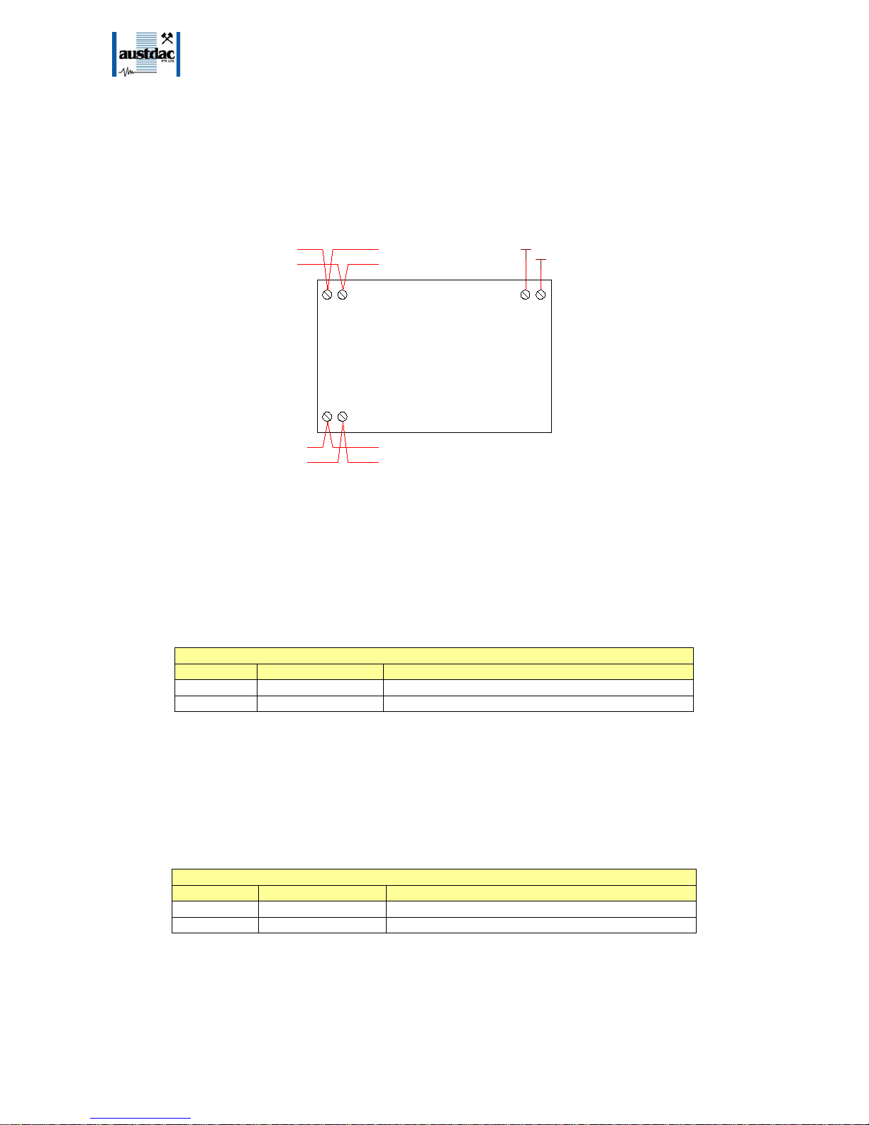
5 TERMINATIONS AND CONNECTIONS
All connections to the repeater are via cage-clamp terminals around the perimeter and near
the front of the DIN rail mounting enclosure, these terminals can accommodate up to 4mm
2
conductors. There are 6 possible connections to the repeater; these are shown in the
following tables and diagrams:
SIG
COM
1 2 14 15
SIG COM
+VE -VE
REPEATER TYPE A2WCC T2
16 17
SIG COM
SECONDARY NETWORK
PRIMARY NETWO RK
SIG
COM
+12V
-12V
SECONDARY NETWORK
PRIMARY NETWORK
12V I.S.
PSU
Figure 4 Repeater connection diagram
5.1 POWER INPUT PORT
The repeater operates from a nominal 12 volt DC supply. The power supply operating
range is from 7.5 volts through to 12.6 volts. The SILBUS-A2WCCT2 consumes less than
26mA from the power supply. The table below shows the power input port connection
details.
POWER INPUT PORT TERMINATIONS
TERMINAL DESIGNATION DESCRIPTION
14 +VE 12V POWER SUPPLY +VE INPUT
15 -VE 12V POWER SUPPLY –VE OR COMMON INPUT
Table 1 Power input port termination details
5.2 PRIMARY SILBUS NETWORK PORT
The primary SILBUS network port provides a means for the repeater to be connected to the
primary SILBUS network. Any connections to a SILBUS field bus network pair should be of
a multi-drop nature with spur lengths kept to a minimum. This will minimize any reflections
and therefore communications errors in the SILBUS network.
PRIMARY SILBUS NETWORK PORT TERMINATIONS
TERMINAL DESIGNATION DESCRIPTION
16 SIG SILBUS NETWORK SIGNAL
17 COM SILBUS NETWORK COMMON
Table 2 Primary SILBUS network port termination details
The table above shows the primary SILBUS network port connections.

SSIILLBBUUSS RREEPPEEAATTEERR
88 OOFF 1100
120-321-12
TTYYPPEE
SILBUS-A2WCCT2 UUSSEERR''SS MMAANNUUAALL
IIssssuuee:: 001
1
5.3 SECONDARY SILBUS NETWORK PORT
The secondary SILBUS network port provides a means for the repeater to be connected to
the secondary SILBUS network. Any connections to a SILBUS field bus network pair should
be of a multi-drop nature with spur lengths kept to a minimum. This will minimize any
reflections and therefore communications errors in the SILBUS network.
SECONDARY SILBUS NETWORK PORT TERMINATIONS
TERMINAL DESIGNATION DESCRIPTION
1 SIG SILBUS NETWORK SIGNAL
2 COM SILBUS NETWORK COMMON
Table 3 Secondary SILBUS network port termination details
The table above shows the secondary SILBUS network port connections.
6 CERTIFICATION
The repeater type SILBUS-A2WCCT2 has been awarded IECEx certification under IECEx
TSA 07.0002X, Ex ia I, as part of the Dupline / SILBUS system.
The certification requires that the A2WCCT2 be mounted within a host enclosure that
provides a minimum ingress protection of IP54 (IP55 for Queensland Australia).
1 2 14 15
SIG
COM
+VE
-VE
SECONDARY NETWORK
REPEATER TYPE A2WCCT2
16 17
SIG
COM
PRIMARY NETWORK
Figure 5 Repeater segregation and isolation levels
Because of the segregation and isolation between the various ports of the SILBUSA2WCCT2 it may be used to provide isolation and segregation between non-intrinsically
safe and intrinsically safe SILBUS networks without the use of signal draining zener
barriers. As shown in the above figure the primary network port is isolated from the power
supply and secondary network ports to IEC60079-11 375 volts as indicated by the green
dotted lines. The power port and secondary network are not isolated from each other.

SSIILLBBUUSS RREEPPEEAATTEERR
99 OOFF 1100
120-321-12
TTYYPPEE
SILBUS-A2WCCT2 UUSSEERR''SS MMAANNUUAALL
IIssssuuee:: 001
1
7 SOFTWARE REVISION AND DISPLAY
The software version of the repeater type SILBUS-A2WCCT2 will vary as its functionality is
improved at the request of our customers. The software version is given in the format
ZPR176-n, where ZPR176 represents the product code and n represents the revision level.
E.g. ZPR176-1
The software version can be determined by reading the label on the processor chip U2
mounted on PCB0266A. The following table records the software revision history of the
SILBUS-A2WCCT2 repeater.
SILBUS-RX4D SOFTWARE REVISION HISTORY
VERSION DATE
ZPR176-1 2004 First production release
Table 4 Repeater software revision history

SSIILLBBUUSS RREEPPEEAATTEERR
1100 OOFF 1100
120-321-12
TTYYPPEE
SILBUS-A2WCCT2 UUSSEERR''SS MMAANNUUAALL
IIssssuuee:: 001
1
8 SPECIFICATIONS
Name .......................................................................................................................... Repeater
Type............................................................................................................SILBUS-A2WCCT2
Primary network port segregation................................................................ IEC60079-11 375v
Primary port isolation...........................................................................................................4kV
Terminations................................................................................Cage clamp 4mm
2
maximum
Size................................................................................100mm (W) x 75mm (H) x 110mm (D)
Mass ..................................................................................................................................260g
Fixing ..........................................TS35 DIN rail or screw mount M4 on 85mm x 61mm centres
Ingress protection ...............................................................................................................IP20
Enclosure material.............................................................Polycarbonate (30%GV) UL 94 V-1
Enclosure colour................................................................................................RAL 7032 Grey
Terminal material...............................................................................Polycarbonate UL 94 V-2
Terminal block colour..........................................................................................................Blue
Operating temperature range.................................................................................. 0ºC to 40ºC
Storage temperature range..................................................................................-20ºC to 80ºC
Operating relative humidity range................................................10% to 90% Non condensing
Power supply operating voltage range...................................................................7.5v to 12.6v
Power supply current consumption................................................................120mA maximum
 Loading...