

Aussie Uluru 3 Burner, Uluru 4 Burner Owner's Manual

Aussie
TM
TM
ULURU
LP Gas Grill
Assembly and Use Manual
For Customer Service, call
1-800-251-7558
www.aussiegrill.com
• READ AND FOLLOW INSTRUCTIONS CAREFULLY BEFORE ASSEMBLY OR USE.
FAILURE TO FOLLOW THESE INSTRUCTIONS COULD RESULT IN DEATH, SERIOUS
BODILY INJURY, AND/OR PROPERTY LOSS.
• FOR OUTDOOR HOUSEHOLD USE ONLY. NOT FOR COMMERCIAL USE.
• SOME PARTS MAY CONTAIN SHARP EDGES - ESPECIALLY WHERE NOTED IN THIS
MANUAL! WEAR PROTECTIVE GLOVES IF NECESSARY.
• THESE INSTRUCTIONS MUST BE KEPT WITH THE CONSUMER AND RETAINED FOR
FUTURE USE.
• PORCELAIN COATING CAN CHIP DURING ASSEMBLY. WEAR SAFETY GLASSES WHILE
ASSEMBLING GRILL.
FOR YOUR SAFETY
If you smell gas:
1. Shut off gas to the appliance.
2. Extinguish any open flame.
3. Open Lid.
4. If odor continues, immediately call your gas
supplier or your fire department.
This manual intended for the following models: 8362 & 8462.
©Aussie™ Grill Company 2001
FOR YOUR SAFETY
1. Do not store or use gasoline or other
flammable vapors and liquids in the
vicinity of this or any other appliance.
2. An LP cylinder not connected for use
shall not be stored in the vicinity of this
or any other appliance.

2
I. IMPORTANT SAFEGUARDS........................................2
II. Assembly Instructions.......................................................5
Step 1 - Construct Cart Cabinet....................................5
Step 2 - Insert Door Center Post ..................................5
Step 3 - Install Wheels/ Casters....................................5
Step 4 - Install Side Tables.............................................6
Step 5 - Body/Cart Assembly ......................................6-7
Step 6 - Install Door ......................................................7
Step 7 - Install Tray........................................................8
Step 8 - Install Burners..................................................9
Step 9 - Install Bottom Body Panel/Grease Tray...........10
Step 10 - Ceramic Briquette Trays/ Cooking Grids.......10
Step 11- Hood Handle/ Heat Indicator...........................10
Step 12- Attach LP Cylinder Brackets ..........................11
Step 13- Attach LP Cylinder to Grill .............................11
Step 14 - Leak Testing..................................................12
III. Operating and Maintaining Your LP Gas Grill................13
A) Gas, Cylinder, Hose and Regulator Info...................13
1) LP Hose & Regulator Assembly............................13
2) LP Gas Cylinder.....................................................13
3) Connect/ Disconnect LP Gas Cylinder...................13
C) Operating the LP Gas Grill......................................15
1) Preparation Before Cooking.................................16
2) Lighting Using Integra Spark Ignition...................16
3) Manual Lighting of the Grill..................................17
4) Check your Flame................................................18
5) Grill Cooking.........................................................18
6) Roasting...............................................................18
7) End of Cooking Session......................................18
8) Turning Off Your LP Gas Grill..............................18
D) Care and Maintenance..........................................18-19
1) Porcelain Coated Cooking Surfaces....................24
2) Burner Maintenance.............................................19
3) Ceramic Briquettes...............................................20
4) Bottom Panel/Grease Tray ..................................20
5) Cleaning the Grill Body.........................................20
6) Preventive Maintenance.......................................20
7) Storage....................................................................20
IV. Assembly Diagram...................................................21-22
V. Parts List...................................................................23-25
VI. Troubleshooting.....................................................26-27
B) Before Using Your Grill...............................................14
1) Selecting a Location............................................14
2) Precautions..........................................................14
3) Leak Testing.........................................................15
IMPORTANT SAFEGUARDS
FAILURE TO FOLLOW THESE SAFEGUARDS COULD RESULT IN DEATH, SERIOUS
BODILY INJURY, AND/OR PROPERTY LOSS. READ AND FOLLOW ALL INSTRUCTIONS
CAREFULLY BEFORE ASSEMBLY OR USE OF THE LP GAS GRILL.
1. WARNING! Read and follow all instructions.
2. For Household Outdoor Use Only Do Not Use Indoors or on recreational vehicles
or boats. Never use as a space heater. Not for
commerical use.
3. WARNING! To reduce the risk of serious or
fatal injury from breathing toxic fumes and from
explosion and fire as a result of leaking gas,
use only outdoors in an open area with good
ventilation. As with all conventional fuels, the
burning process consumes oxygen and
produces toxic gases, including carbon
Monoxide. In addition, the combustion products
of such fuels, including liquefied petroleum
(LP), contain chemicals known to the state of
VII. Important Notice-LP Cylinder with OPD.......................28
VIII. Limited Warranty...........................................................29
California and other authorities to cause cancer,
birth defects and other reproductive harm.
4. Place your Liquefied Petroleum (LP) gas grill
on a firm, level surface. Grill should be setup
away from high traffic areas and combustible
materials.
5. Locate your LP gas grill at least 10 feet away
from your house or any building. Do not use the
grill in a garage, breezeway, carport, porch, or
in any enclosed area. Do not locate this
appliance under overhead unprotected
combustible surfaces.
6. Have an ABC fire extinguisher accessible.
Never attempt to extinguish a grease fire with
water or other liquids.
©Aussie Grill Company 2001

7. WARNING! If your grill catches on fire:
3
• If the fire involves the cylinder, leave it alone,
evacuate the area and call the fire department.
• If the fire involves one of the hoses, and you can
safely reach the propane cylinder valve, shut the
valve off by turning LP cylinder valve handle
clockwise to a full stop.
• If the fire is in the grill portion and you can safely
reach the control knobs, turn them off by turning
knobs clockwise. If you cannot safely reach the
control knobs or the LP cylinder valve, call the fire
department.
• If there is any type of fire that threatens either
personal safety or endangers property, call the
fire department.
8. Check the Bottom Body Panel for grease buildup.
Remove excess grease to avoid a grease fire in the pan.
Never use the grill without Bottom Body Panel and
Grease Tray in place.
9. WARNING! If you notice grease or other hot material
dripping from the grill onto valve, hose, or regulator, turn
off gas supply immediately. After the grill has cooled,
determine the cause and correct it. After cleaning the
valve, hose and regulator, perform a leak test before
continuing use. See Before Using Your LP Gas Grill
section of this manual for correct leak test procedures.
10. This installation must conform with local codes or, in the
absence of local codes, with either the National Fuel Gas
Code, ANSI Z223.1, or CAN/CGA-B149.2, Propane
Installation Code.
16. Check the LP gas grill for gas leaks and burner
obstructions before each use.
WARNING! Do not use a flame to check for gas
leaks. See Before Using Your LP Gas Grill section of
this manual for correct leak test procedures. A clogged
burner tube can lead to a fire beneath grill.
17. DANGER! If you see, smell, or hear the hiss of
escaping gas from the LP cylinder:
A. Get away from the cylinder.
B. Do not attempt to correct the problem yourself.
C. Call your local fire department.
18. WARNING! Do not operate an LP gas grill if you
have knowledge of or suspect a gas leak.
19. Always inspect the gas hose and regulator assembly
before each use. Always turn the LP cylinder to the
“Off” position before inspecting parts. If the hose is cut,
damaged, or showing signs of excessive abrasion or
wear, do not use the LP gas grill. Contact the
manufacturer, as the hose must be replaced with an
assembly specified by the manufacturer prior to further
use of the LP gas grill.
20. WARNING! Before lighting the LP gas grill, open
hood to prevent an explosion from gas build-up.
See Operation of Your LP Gas Grill section
21. If any burner does not light, turn off all gas control
knobs. Leave the hood open and wait five minutes
before attempting to light.
11. If an external electrical source is utilized, the outdoor
cooking appliance, when installed, must be electrically
grounded in accordance with local codes or, in the
absence of local codes, with the National Electrical
Codes, ANSI/NFPA 70, or the Canadian Electrical Code.
CSA C22.1.
12. Keep any electrical supply cord and the fuel supply hose
away from any heated surfaces. Electric cords should be
placed away from walkways to avoid a tripping hazard.
13. Combustible materials should never be within
36 in. of the back or sides of your LP gas grill.
14. The Vinyl grill cover must be removed and
placed at least 36 inches from LP gas grill
while in use. The grill cover is made of a
flammable material. The grill must be cooled
before putting the cover back on the grill.
15. WARNING! Always Store LP Cylinders upright
and where temperatures do not exceed 125 degrees
Fahrenheit. Never store a spare or disconnected LP
cylinder under or near this LP gas grill.
22. If any burner goes out during operation, turn off all gas
control knobs. Open the hood and wait five minutes
before attempting to light.
23. Excercise reasonable care when using this LP gas grill.
Never leave grill unattended during use or cleaning.
24. Never allow children to operate or play near an LP gas
grill. Keep animals and bystanders out of the grill area.
25. Always turn off the LP gas cylinder at the cylinder valve
when not in use. Allow grill to cool before handling parts
or cleaning.
26. WARNING! Do not move an LP gas grill when in
use or hot.
27. WARNING! Never touch hot surfaces. Use heat
resistant gloves, long-handled tongs, or cooking mitts
at all times. The grill will become very hot. Open the
hood carefully when cooking to avoid burns from the
hot air and steam trapped inside.
28. Use only the hose and regulator assembly
that is supplied with your LP gas grill and/or
specified by the manufacturer.
29. Use of this LP gas grill other than for the intended use,
or alteration of LP gas grill in any way may not be safe
and will void any warranty.
36. Never store an LP gas cylinder indoors (empty or filled).
If storing the gas grill indoors, disconnect LP gas cylinder
and store it outdoors out of the reach of children.
30. Never attempt to repair the LP gas grill or cylinder
yourself. Contact the manufacturer for information
regarding repairs to your grill.
31. LP gas is not natural gas. The conversion or attempted
use of natural gas in an LP unit or LP gas in a natural
gas unit is dangerous and will void your warranty.
32. Do not use charcoal in an LP gas grill. Do not use
aerosols or store flammable liquids or materials near this
LP gas grill.
33. WARNING! Do not wear loose clothing (example:
hanging shirt tails, clothing with frills, etc.) around an LP
gas grill while in use or hot.
34. Never use an LP cylinder if it shows signs of: dents,
gouges, bulges, fire damage, corrosion, leakage,
excessive rust or other forms of visual external damage;
it may be hazardous and should be checked by a
Liquefied Petroleum supplier. Do not use an LP cylinder
with a damaged valve.
35. Even though your LP cylinder may appear to be empty,
gas may still be present and the cylinder should be
transported and stored accordingly.
37. Never leave an LP cylinder inside a vehicle which may
become overheated by the sun.
38. Never lean your body over the LP gas grill when lighting
it or while it is in use or hot.
39. Do not attempt to disconnect, move or alter any gas
fittings while your LP gas grill is in operation.
40. Your LP gas grill should be cleaned on a regular basis.
Refer to Care and Maintenance section in this manual.
41. This LP gas grill is not designed to be used with more
than 50% of the cooking area as a solid plate (griddle).
Full coverage of plates will cause excessive heat and
could damage the grill.
42. Never douse the grill with water when its surfaces are
hot because it may cause grease to splatter or the
porcelain cooking grids and hood to break.
43. When not in use, the LP cylinder valve must be
turned to “Off” position.
— NOTICE —
AUSSIE GRILL COMPANY STRIVES TO BE A QUALITY SUPPLIER OF CONSUMER PRODUCTS. IF WE INADVERTENTLY
OMITTED ANY PARTS NEEDED FOR ASSEMBLY, OR YOU NEED TROUBLESHOOTING INFORMATION, PLEASE CONTACT
US USING OUR TOLL FREE NUMBER. THANK YOU FOR PURCHASING AN AUSSIE GRILL COMPANY PRODUCT.
1-(800)-251-7558
8 am - 5 pm E.S.T Mon. - Fri.
1-(423)-639-1171 (TELEPHONE)
1-(423)-639-2570 (FAX)
CONSUMER SERVICE DEPARTMENT
AUSSIE GRILL COMPANY
1500 INDUSTRIAL ROAD
GREENEVILLE, TN. 37745 USA
www.aussiegrill.com
ASSEMBLY INSTRUCTIONS for ULURU MODELS
IMPORTANT! Please Read!
Please read all the instructions in this manual before beginning assembly.
Follow them in order.
This manual covers the 3- and 4-Burner Uluru Grill models. Use the steps that pertain to your model.
PREPARATION FOR ASSEMBLY: Two People will be required for removing parts from the
carton and for some assembly. Look in the Parts List on pages 23-25 under your model number to
find the exact parts you need. Do not throw away any packaging until you have located all the parts.
Remove all the parts from the carton and lay them on a smooth, clean surface. (You may cut
the carton, spread it out, and use it as a pad to protect part finishes.
Assembly Instructions
NOTE: Refer to Assembly Diagram on pages 21 and 22. It may be easier to position grill on its
back side for assembly. Do not tighten bolts and nuts completely until told to do so.
Bolts are shown actual size.
Tools Required:
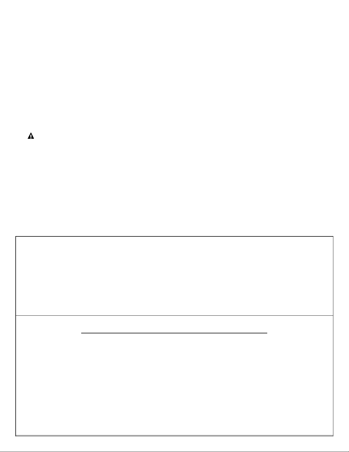
Step 1 - CONSTRUCT CART CABINET
*Cabinet Panels are labeled for your convenience.*
24
33
A)•Secure left end of Cart Bottom Panel(33) to Left
Bolt,
M6x15
Item#23
Side Panel(24) using three M6X15 screws
andnuts.
B)•Secure right side of Cart Bottom Panel(33) to
Right Side Panel(35) using three M6X15 screws
and nuts.
Axle
Holes
36
C)•Secure left side of Top Panel(36) to Left Side
Panel(24) using two M6X15 screws and nuts.
Secure right side of Top Panel(36) to Right
Side Panel(35) using two M6X15 screws and nuts.
D)•Secure Rear Panel(26) to rear of Top
Panel(36) and to rear of Bottom Panel(33)
35
using six M6X15 screwsand nuts.
STEP 2 - INSERT DOOR CENTER POST & DOOR MAGNET
36
•Insert Door Center Post(31) between Top Panel(36) and Bottom
Panel(33) using four M6X15 screws and nuts.
Bolt,
M6x15
Item#23
Nut
M6
Item#25
Threaded
Caster
Holes
35
Nut
M6
Item#25
33
19
34
•Install one Magnet Assembly(32) onto each Bottom Panel and Top
Panel using two M6X15 screws and nuts for each Magnet
Assembly.
STEP 3 - INSTALL WHEELS/ CASTERS
•Insert Axle(19) through axle holes in Left Side Panel. Install the
Wheels by placing them on the axle and pushing into position until a
click is heard or until they will not pull off.
•Install Caster(34) by threading the caster into the end of the Right
Side Panel and hand tighten until it stops.
5
STEP 4 - INSTALL
SIDE TABLES
24
•Place Side Table(14) over Left Side
Panel(24) and secure by installing two
M6X15 screws through side table and into
threaded hole.
Completely tighten these 2 screws.
Bolt,
M6x15
Item#23
Threaded
Hole
14
•Secure the other Side Table over the Right Side Panel in
the same manner.
Make sure side table screws are completely tightened.
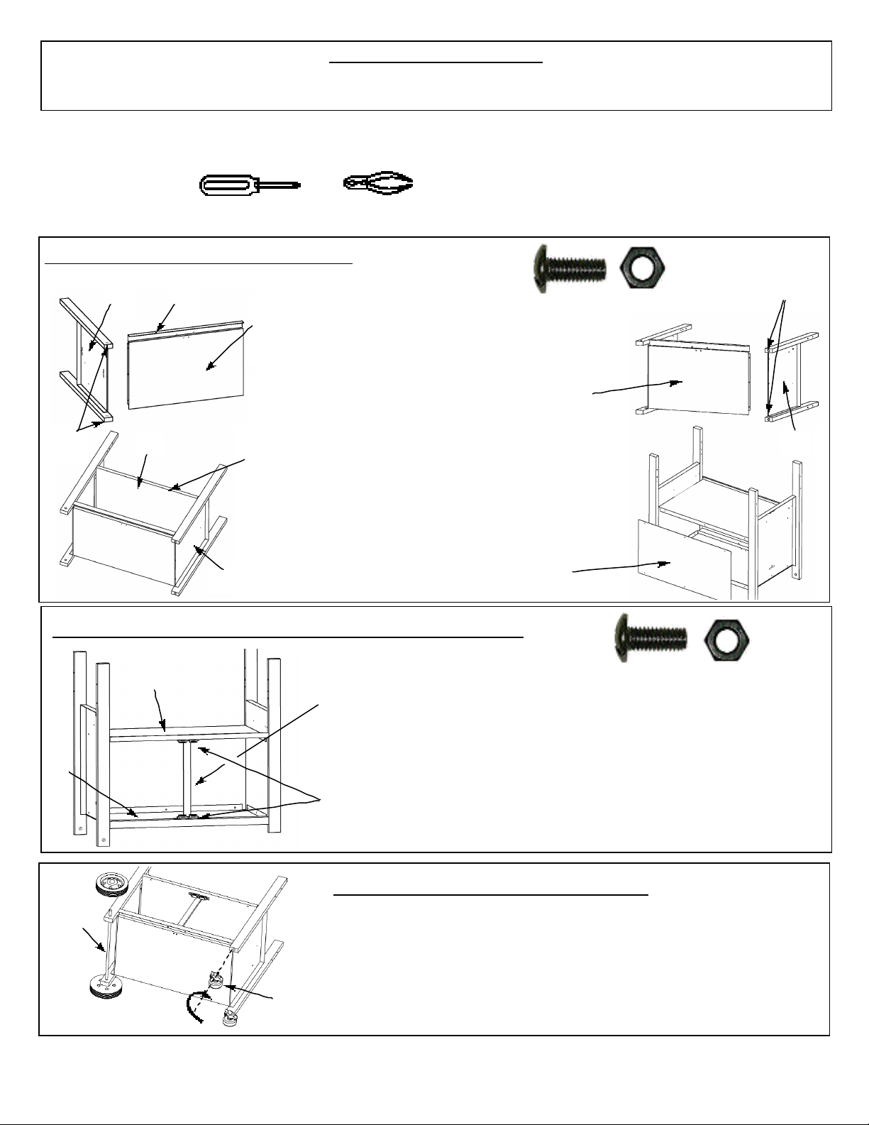
STEP 5 - BODY/ CART ASSEMBLY
•Remove loose contents from Grill and remove Bottom Panelas
shown. Lay Grill Body(8) on its back with control panel up. Place
Grill Body between Cart Legs and Side Tables with Hose and
Regulator(Item#10) on wheel Leg end. Do not lay Grill Body on,
or step on Hose and Regulator.
•Align slotted holes on side of Grill Body with holes through edges
of legs. Hold Spacers between Leg and Body (Needle Nose
Pliers may help) and insert Body Bolts through Leg, Spacers, and
slotted holes in Grill Body. Secure using Wing Nuts, but only
partially tighten. Repeat assembly for remaining three Cart legs.
Bolt
M6X110
Item#40
Wing Nut
Item#41
Spacer
Item#39
Remove Bottom Panel
Hose/
Regulator
(Item#10)
Spacers(39)
WingNuts(14)
M6X110
Bolts
(40)
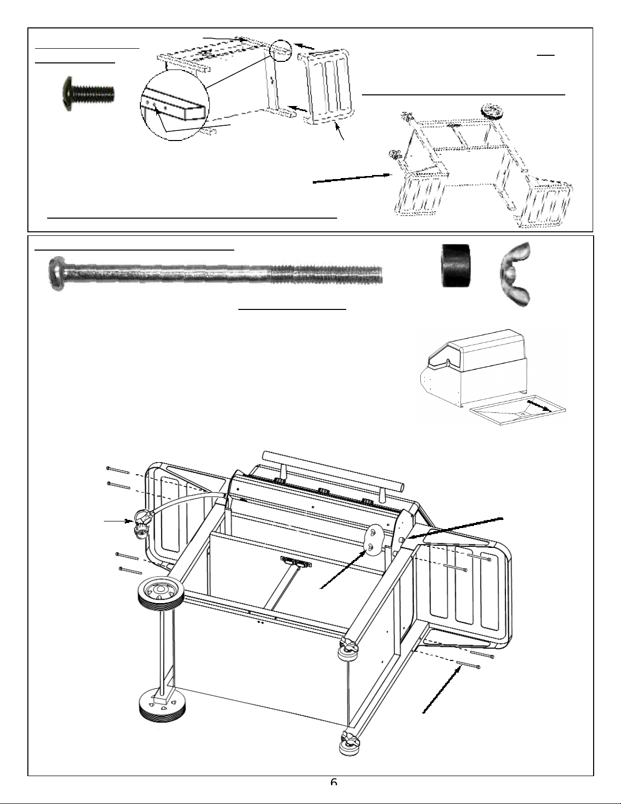
STEP 5 - BODY/ CART
ASSEMBLY (CONTINUED)
•Using a second person, turn full grill
assembly upright placing wheels and
legs/casters on the ground. Grill Body
should slide down and seat itself within
the slotted holes. If not, slightly loosen
the Body Bolts and push Body down
at the corners.
4
Tighten all Body Bolts and Wing
Nuts in the following sequence:
Item Qty.
1. Bottom Panel (Item#33) 9 Bolts & Nuts
2. Top Panel (Item#36) 7 Bolts & Nuts
3. Center Post (Item#31) 4 Bolts & Nuts
4. Body (Item#8) 8 Bolts &WingNuts
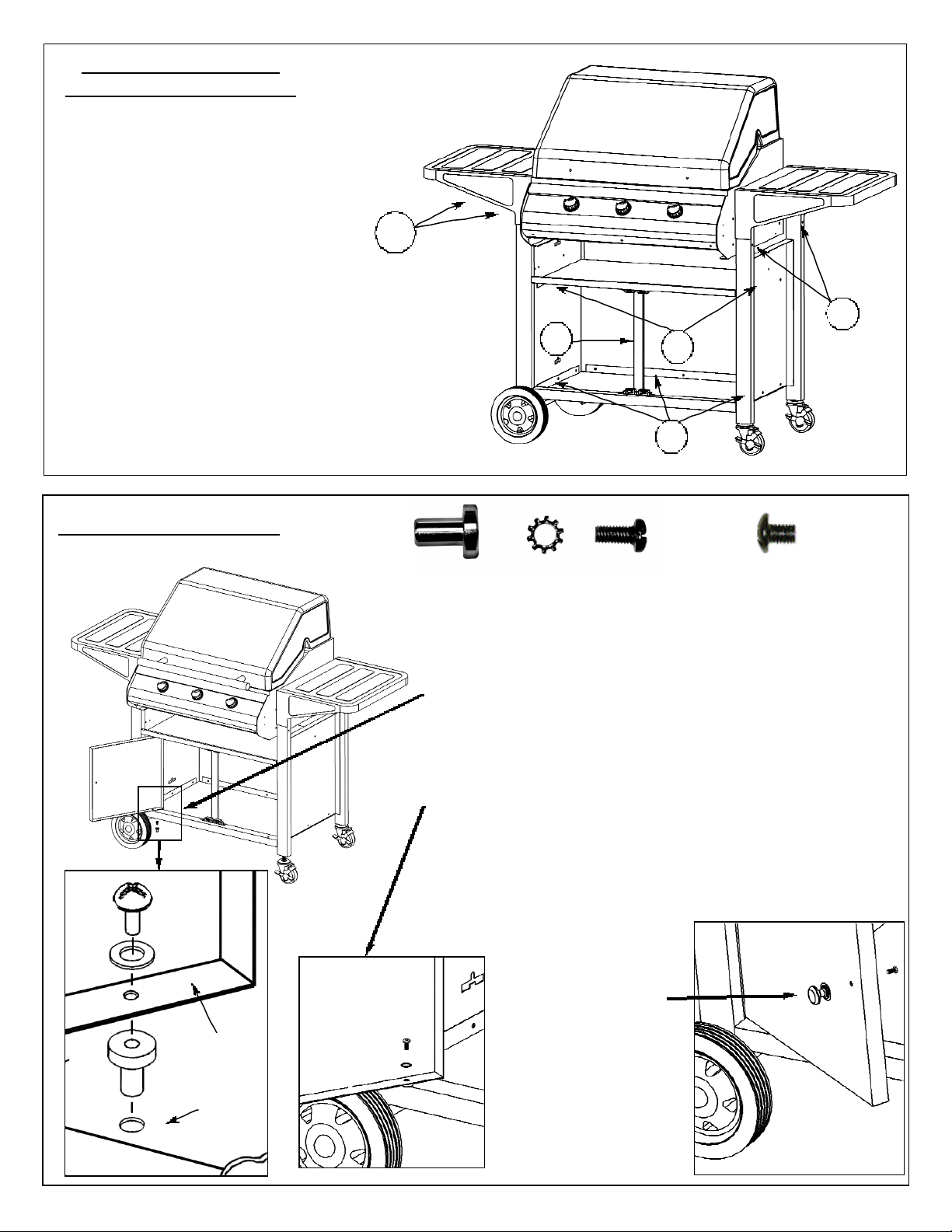
STEP 6 - INSTALL DOOR
Door Pin
Item#28
Note: Both doors are the same and can be
used in either the left or right position.
aligning screw hole in Door with screw hole in Pin.
Install M5X10 screw through Door and into Pin.
4
3
2
1
M5X10
Screw
Item#29
M4X6
Screw
Item#53
•While holding Pin in place move door into position
Door
Bottom
Panel
•Install left Door(27) by inserting Pin(28) through the
hole in left side of the Bottom Panel. Place Door into
position and install M5X10 screw through Door and
into Pin.
•Repeat with Right Door.
•Align Door Knob(30)
with mounting hole in
Door. Insert M4X6
screw through Door
into Knob and tighten.
Repeat for other
Knob.

STEP 7 - INSTALL TRAY
(Reference Assembly Diagram page 22.
See Track Detail)
37
M4x12
Flat Head
Screw
Item#15
M4
Nut
Item#44
M4x10
Bolt
Item#17
A)•Secure Right Track(38) to Right Side Panel by
securing with two M4X12 flat head screws and nuts.
The nuts should be installed so they are on the outside of the cabinet. Secure Left Track(21) to Left
Side Panel in the same manner.
B)•Insert Tray(37) into track. With Tray pushed
com pletely to the closed position, install one
M4X10 Bolt(17) through threaded hole on each
side of the Grill Cart and Tray to help secure the
tray in position. Tighten screws completely.
Install this screw
1st for alignment.
Item #15
M4X12 Flat
Head
Screw
Item #17
Bolt M4X10
8
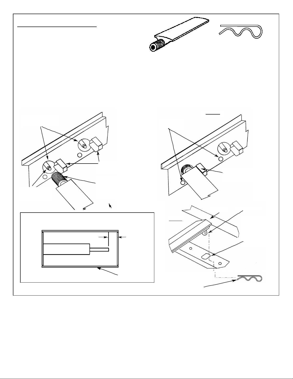
STEP 8 - INSTALL BURNERS
(Reference Assembly Diagram page 8)
•Remove plastic covering from Burner(3)
and remove Cotter(4) Pin from Burner Peg
•Fit venturi end of Burner through hole in the inside firewall
(behind Control Panel) and onto Gas Control Valve Nozzle
(FIG. A.) Be careful not to bend or force Gas Collector
•Place other end of burner on lower shoulder of rear
firewall so Burner Peg rests in Burner Locator Hole
as shown ( FIG. B.)
Holes in Front
Firewall
Gas Nozzle
Control Valve
Gas Collector
and Electrode
Venturi end of
Burner inserted
over gas nozzle
Repeat above steps for remaining burners.
Manual
Lighting
BURNER
(Item #3)
COTTER PIN
(Item #4)
•Using pliers, insert Cotter Pin
through hole in Burner Peg to
secure. This is easier done
from rear, underside of grill.
FIG. A
Top Plate of
Gas Collector
REFERENCE: ELECTRODE GAP
Adjust Tab if greater than 3/16”.
ELECTRODE
3/16”
GAP
MAX.
TAB-GAS
COLLECTOR
FIG B
Cotter Pin - Install
from underneath
Backside of grill
Burner
Burner Peg
Burner
Locator
Hole in
Lower
Shoulder
9
 Loading...