

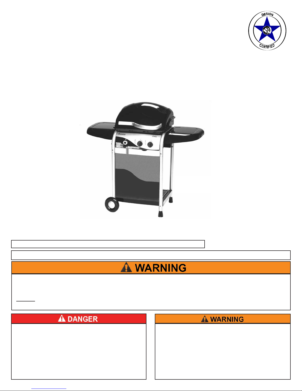
Aussie Joey 7110 Assembly And Use Manual
Aussie
®
bbyy MMeeccoo
®
LP Gas Grill
Assembly and Use Manual
Joey
TM
For Customer Service, call 1-800-251-7558 or visit our web site at www.meco.net
FOR OUTDOOR HOUSEHOLD USE ONLY. NOT FOR COMMERCIAL USE.
• Failure to follow these instructions could result in fire or explosion which could cause death,
serious personal injury, or property damage.
• Read and follow instructions carefully before assembly or use.
• Do not
use this product for any other purpose than which it is intended.
• These instructions must be kept with the user. SAVE THESE INSTRUCTIONS.
If you smell gas:
1. Shut off gas to the appliance.
2. Extinguish any open flame.
3. Open lid.
4. If odor continues, keep away from the
appliance and immediately call your gas
supplier or your fire department.
1. Do not store or use gasoline or other
flammable vapors and liquids in the vicinity
of this or any other appliance.
2. An LP cylinder not connected for use shall
not be stored in the vicinity of this or any
other appliance.
MMOODDEELL 77111100 SSeerriieess LLiiqquuiidd PPrrooppaannee GGaass GGrriillll
2
I. Assembly Instructions.......................................................2
Parts Illustrations................................................................3
Parts List............................................................................4
Step 1) Cart Assembly........................................................6
Step 2) Assemble Axle, Wheels, & Wheel Covers..............7
Step 3) Assemble Hood/Bowl to Cart................................8
Step 4) Install Grease Cup..................................................8
Step 5) Assemble Sidebraces ............................................9
Step 6) Assemble Side Tables..........................................10
Step 7) Attach Deco Bar and Hood Handle.......................10
Step 8) Attach Front Panels..............................................11
Step 9) Install Flame Diffuser............................................11
Step 12) Install Warming Rack and Cooking Grid.............11
II. Operating Your LP Gas Grill.............................................12
A) Connecting/Disconnecting the Gas..............................12
1) Using Gas................................................................12
2) LP Gas Cylinder......................................................12
3) LP Hose & Regulator...............................................12
a) Connecting LP Gas Cylinder...............................12
b) Disconnecting LP Gas Cylinder............................13
B) Before Using Your Gas Grill........................................13
1) Installation Codes...................................................13
2) Selecting a Location...............................................14
3) Performing a Leak Test..........................................14
4) Lighting the Grill Using the Ignitor...........................15
5) Manual Lighting the Grill.........................................16
6) Check your Flame...................................................16
C. Grill Cooking................................................................16
1) Warming Rack.........................................................17
2) Roasting Cooking....................................................17
3) Operating the Gas Grill............................................17
4) End of Cooking Session..........................................17
III. Care and Maintenance....................................................18
A) Cleaning the Grill.........................................................18
B) Storage........................................................................19
VI. Troubleshooting..............................................................20
VII. Important Notice-LP Cylinder with OPD..........................22
VIII. Limited Warranty.............................................................23
©Meco Corporation
®
2006
— NOTICE —
MECO CORPORATION STRIVES TO BE A QUALITY SUPPLIER OF CONSUMER PRODUCTS. IF
WE OMITTED ANY PARTS NEEDED FOR ASSEMBLY, OR YOU NEED TROUBLESHOOTING
INFORMATION, PLEASE CONTACT US USING OUR TOLL FREE NUMBER. THANK YOU FOR
PURCHASING A MECO CORPORATION PRODUCT.
1-(800)-251-7558
8 am - 6 pm E.S.T Mon. - Fri.
1-(423)-639-1171 (TELEPHONE)
1-(423)-639-2570 (FAX)
CONSUMER SERVICE DEPARTMENT
MECO CORPORATION
1500 INDUSTRIAL ROAD
GREENEVILLE, TN. 37745 USA
www.meco.net
CONTENTS
To reduce the risk of serious bodily injury or death:
·The use of alcohol, prescription or non-prescription
drugs could impair the consumer’s ability to properly
assemble or safely operate this appliance.
·Do not connect LP cylinders until assembly is complete.
ASSEMBLY INSTRUCTIONS
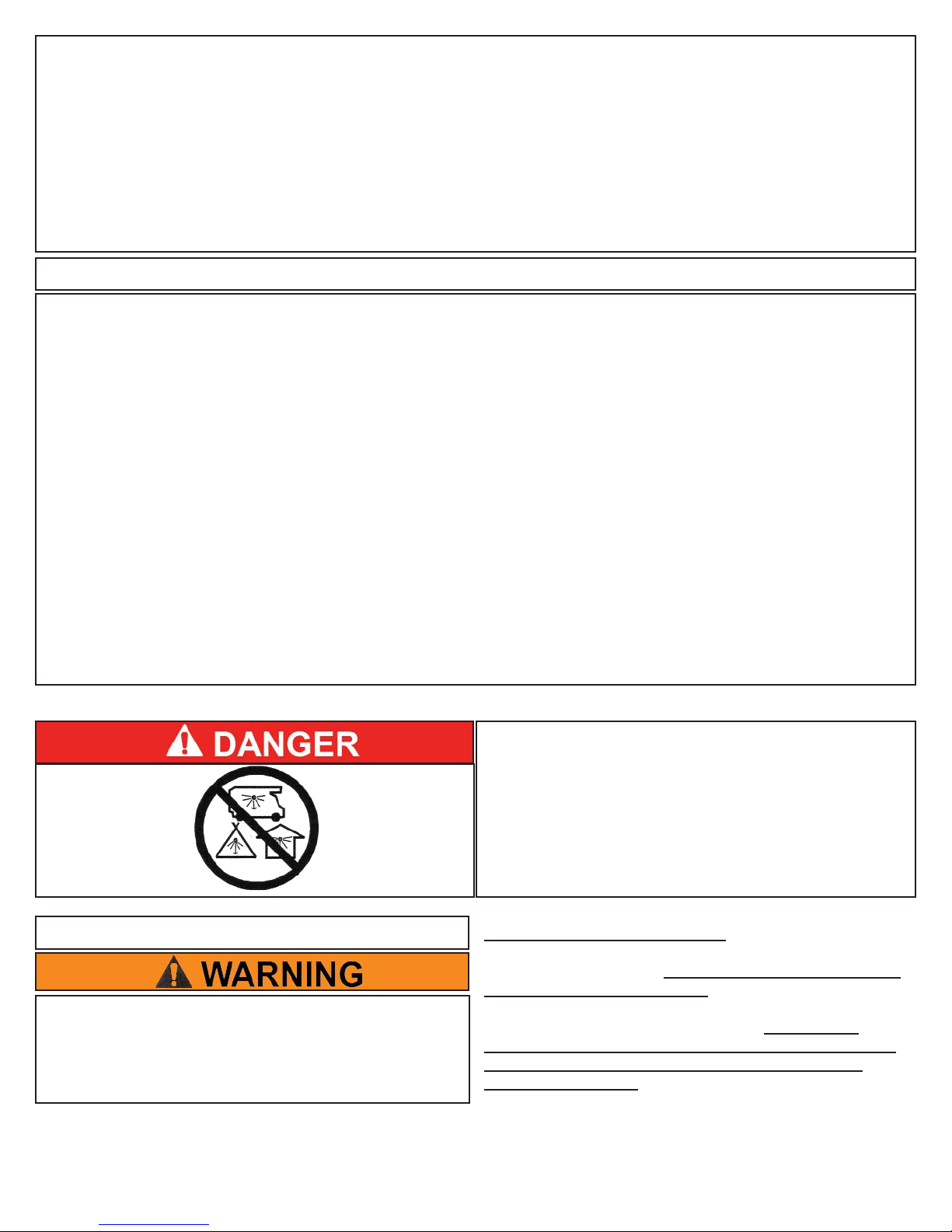
CARBON MONOXIDE HAZARD
This appliance can produce carbon monoxide
which has no odor.
Using it in an enclosed space can kill you.
Never use this appliance in an enclosed space,
such as a camper, tent, car or home.
PREPARATION FOR ASSEMBLY: Remove Grill and all the
packaging from carton and place on floor. Make sure there
are no loose parts. Note: Before using your grill, read the
instructions and your manual. For easier set-up and
assembly, follow instructions of each step in the order they
are written as you look at the diagrams. If accessories
mentioned in certain assembly steps do not come with your
model, skip that step and proceed to the next step that
applies to your model.
3
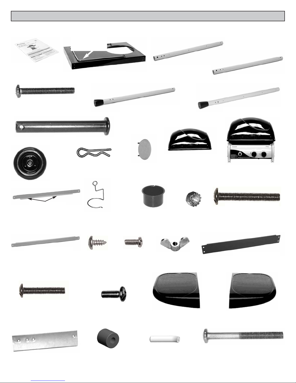
PARTS ILLUSTRATIONS
If you need replacement parts, refer to the Parts Illustrations and the Parts List to find the exact parts you need. If you have
any questions which require help, contact Customer Service and be sure to mention the model number of your grill.
(14) Hood/Bowl Assembly
(13) Hood
(21) Screw,
ST4.0 x 10mm
(20) Left Sidebrace
(22) Bolt,
M4x 10mm
(1) Owner’s Manual
(2) Bottom Shelf
(3) Cylinder
Retainer Clip
(4) Left Front Wheel Leg
(5) Left Rear Wheel Leg
(6) Right Front Fixed Leg
(8) Screw, M5x40mm
(9) Axle
(10) Wheel
(11) Axle Spring Pin
(12) Wheel Cover
(15) Bolt, M6x45mm
(17) Drip Cup
(16) M6 Locknut
(24) Rear
Crossbrace (Black)
(25) Right Side Table(26) Left Side Table
(23) Wingnut, M4
(27) Bolt, M6x15mm
(7) Right Rear Fixed Leg
(18) Drip Cup
Holder
(19) Right Sidebrace
Holes Underside
(29) Heat Shield
(30) Spacer (Deco Bar)
(32) Bolt, M6x60mm
(31) Deco Bar (Hood)
(28) Bolt, M6x30mm
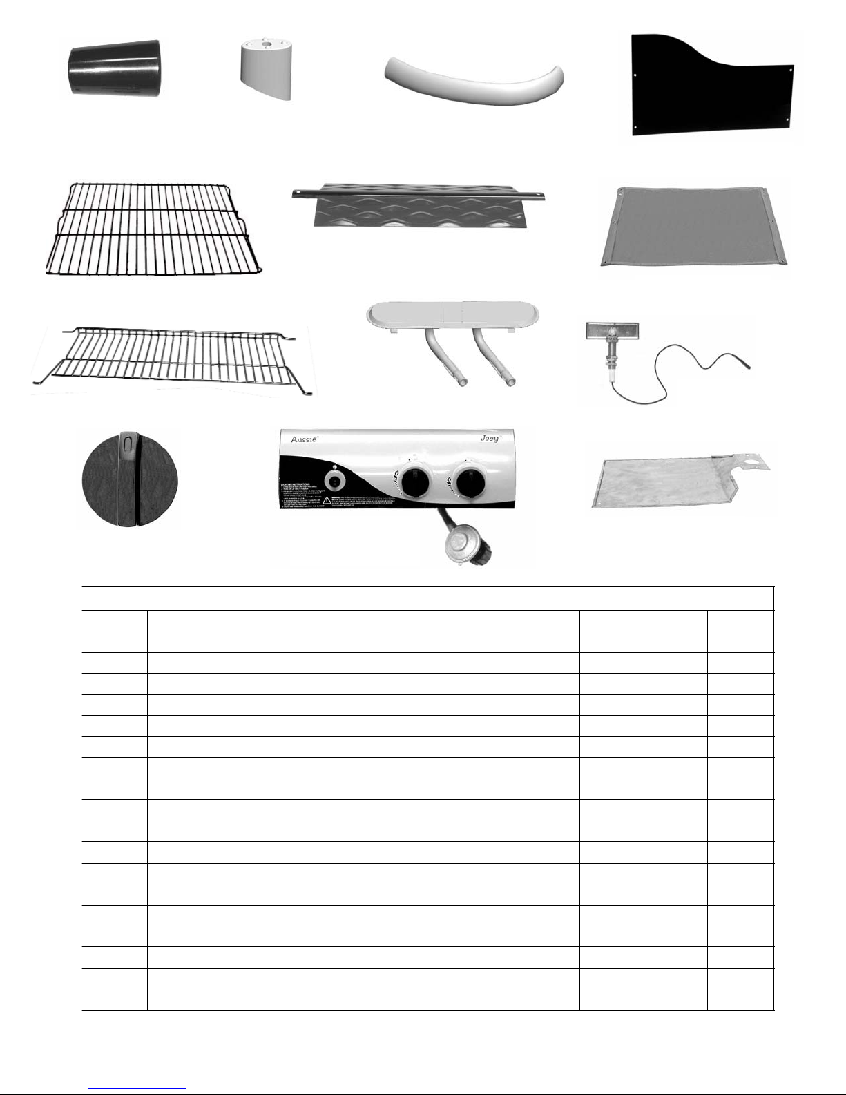
(38) Flame Diffuser
(39) Cooking Grid
(37) Fabric Panel
(43) LP Cylinder
Heat Shield
(41) Main Burner
(42) Main Burner
Electrode
(44) Control Panel
w/Manifold and
Regulator
(40) Warming Rack
ITEM DESCRIPTION PART # QTY.
1 Owner's Manual 03.6602.00
1
2 Bottom Shelf
03.6603.00
1
3 Clip, Cylinder Retainer 03.6205.01 1
4 Left Front Wheel Leg
03.6604.00
1
5 Left Rear Wheel Leg
03.6605.00
1
6 Right Front Fixed Leg
03.6606.00
1
7 Right Rear Fixed Leg 03.6607.00 1
8 Bolt, M5x40 03.6608.00 8
9 Axle 03.6609.00 2
10 Wheel 03.6610.00 2
11 Axle Spring Pin 03.6235.00 2
12 Wheel Cover 03.6611.00 2
13 Hood, Black 03.6612.00 1
14 Hood/Bowl Assembly Black (with Short Handle) 03.6613.00 1
15 Bolt, M6 x 45 03.6614.00 4
16 Locknut, M6 03.4098.00 4
17 Drip Cup 03.6238.00 1
18 Drip Cup Holder 03.6220.00 1
PARTS LIST
4
(36) Front Metal Panel
(35) Hood Handle
(45) Control Knob
(34) Handle Spacer
(Fitted)
(33) Handle Spacer
(Tapered)

5
19 Sidebrace, Right 03.6615.00 1
20 Sidebrace, Left 03.6616.00 1
21 Screw, ST 4.0 x 10 03.6583.00 12
22 Bolt, M4 x 10 (Clear Nickel) 03.6267.00 2
23 Wingnut, M4 Solid (Left Sidebrace) 03.6313.00 2
24 Crossbrace, Rear 03.6617.00 1
25 Right Side Table Black 03.6618.00 1
26 Left Side Table Black 03.6619.00 1
27 Bolt, M6x15 03.6208.00 8
28 Bolt, M6x30 03.4129.00 2
29 Hood Heat Shield 03.6620.00 1
30 Spacer, M6x15mm (Deco Bar) 03.6621.00 2
31 Deco Bar 03.6622.00 1
32 Bolt, M6x60 (Handle) 03.6623.00 2
33 Handle Spacer (Tapered) 03.6624.00 1
34 Handle Spacer 03.6625.00 1
35 Hood Handle 03.6626.00 1
36 Metal Panel, Black 03.6627.00 1
37 Fabric Panel 03.6628.00 1
38 Flame Diffuser 03.6250.00 1
39 Cooking Grid, Porcelain 03.6255.00 1
40 Warming Rack 03.6253.00 1
41 Main Burner 03.6629.00 1
42 Main Burner Electrode 03.6225.00 1
43 Heat Shield, LP Cylinder 03.6595.00 1
44 Control Panel Assy (w/Manifold/Regulator) 03.6630.00 1
45 Knob, Control 03.6589.00 2
PARTS LIST (cont'd)
6
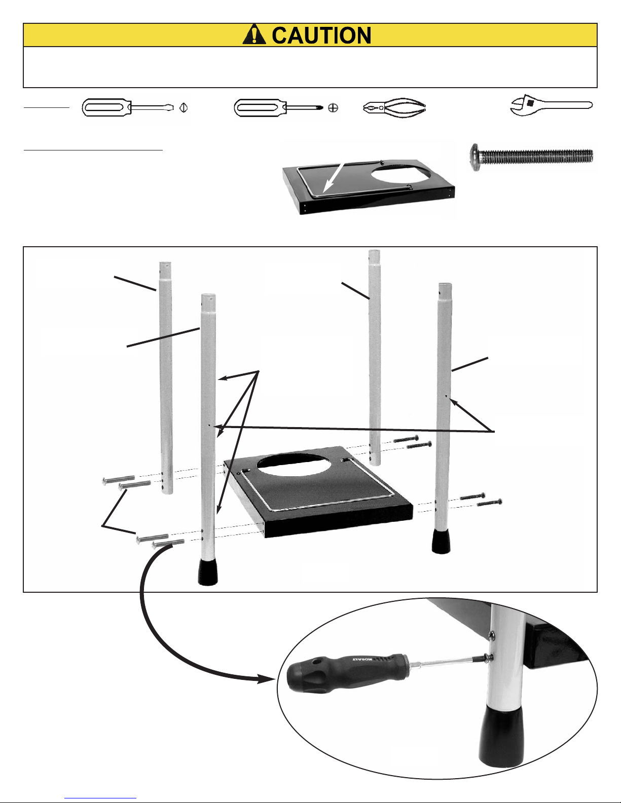
STEP 1) Cart Assembly:
Attach the Legs to the Bottom Shelf with
M5 x 40 Bolts threaded into the Bottom
Shelf holes. Position legs with the holes
exactly as indicated .
(4) LEFT FRONT
WHEEL LEG
To reduce the risk of a cut injury:
· Wear protective gloves when handling parts that have sharp edges.
· Some assembly may require help from another person. Observe where noted.
T
OOLS:
and/or
or
(3) LP CYLINDER CLIP
(5) LEFT REAR
WHEEL LEG
(6) RIGHT FRONT
FIXED LEG
(7) RIGHT REAR
FIXED LEG
(8) M5 X 40
BOLTS
FIG. 1A
FIG. 1B
(8) M5 X 40 BOLT
8 PC
(2) BOTTOM SHELF
1 PC
NOTE:3-HOLES
INSIDE OF FRONT
FIXED LEG AND
WHEEL LEG
THESE HOLES
FACE OUTWARD
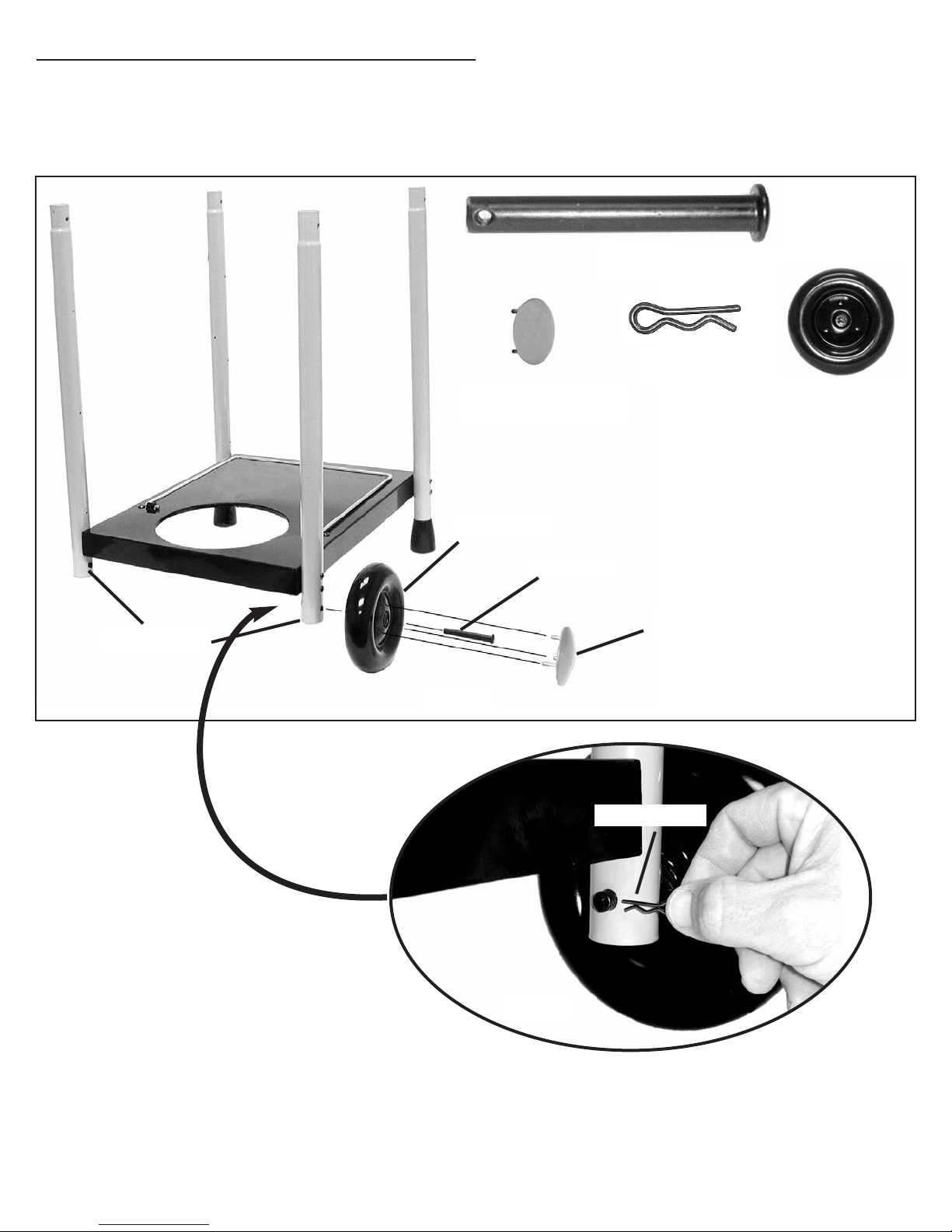
STEP
2) Assemble Axle, Wheels & Wheel Covers:
7
(10) WHEEL
2 PC
(12) WHEEL COVER
2 PC
Push Axle through center hole in Wheel and through lower hole in each leg. (FIG. 2A) Insert Axle
pin through small hole in end of Axle until it snaps over it. (FIG. 2B) Align Wheel Cover pins with
3-holes in Wheel and push flush against Wheel.
(10) WHEEL
(12) WHEEL
COVER
(9) AXLE
WHEEL LEGS
FIG. 2A
(11) AXLE PIN
2 PC
FIG. 2B
(9) AXLE
1 PC
(11) AXLE PIN
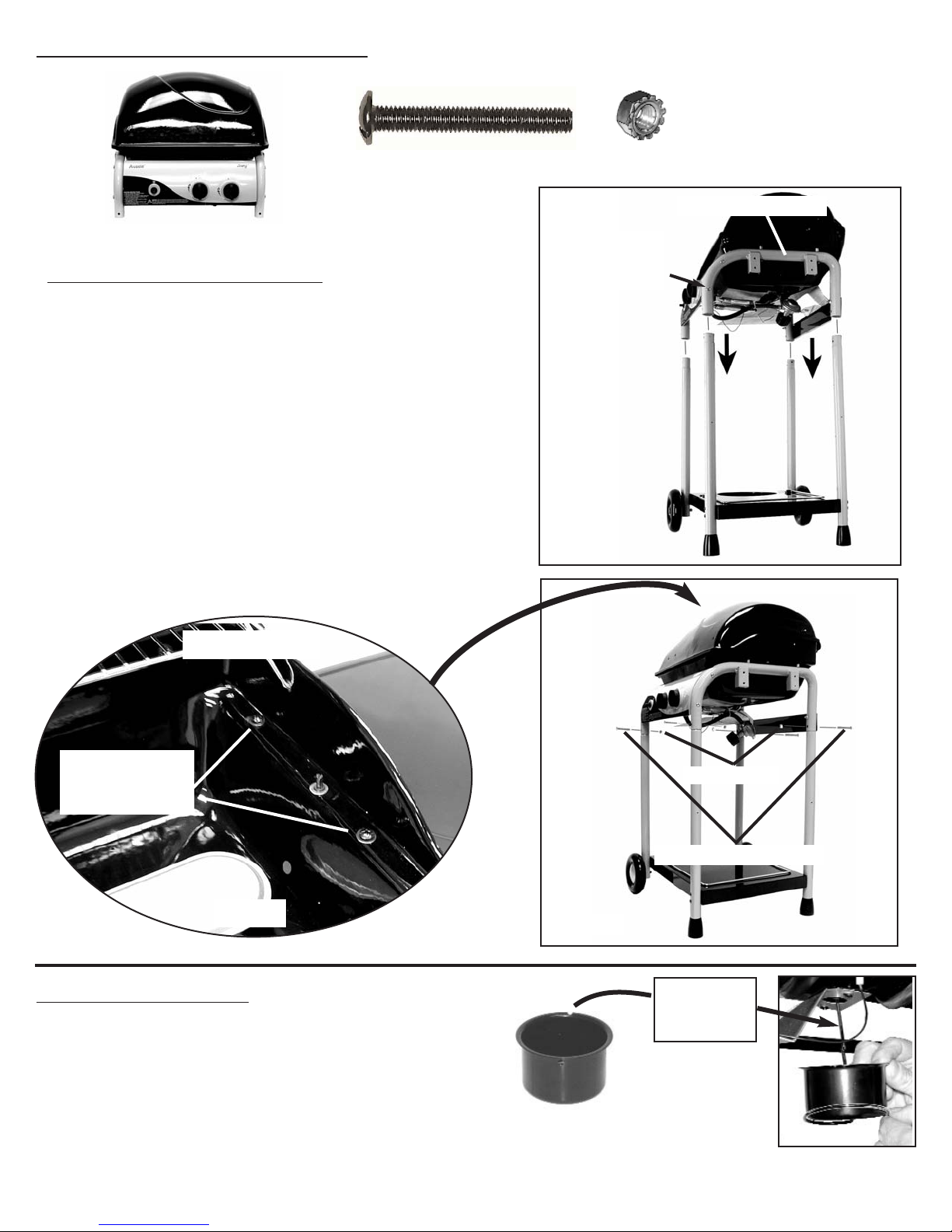
Step 4) Install Drip Cup:
Insert Drip Cup into Drip Cup Holder ring until
the cup flange is flush with the ring and the
notch in the lip of the cup fits the vertical
hanger wire.
(17) DRIP CUP
Align groove
with vertical
wire
S
tep 3) Assemble Hood/Bowl to Cart:
(15) BOLT, M6X45
4 PC
(16) M6 LOCKNUT
4 PC
FIG. 3A
FIG. 3C
(16) BOLT, M6X45
(15) M6 Nut
(14) HOOD/BOWL ASSEMBLY
Bowl Bracket Legs
8
Bowl/Leg Bolts
Left and Right
Sides
FIG. 3B
View Inside Bowl
NOTE: REQUIRES 2-PERSONS
· With Cart upright, align Bowl Bracket legs with
Cart legs. (FIG. 3A)
· Lower Hood/Bowl so ends of Cart legs insert
into Bowl Bracket legs.
· Press downward until leg screw holes align.
NOTE: If cart legs do not align and fit into
Bowl Bracket legs easily, loosen the Control
Panel bolts slightly. Then open the Hood and
loosen the 2-Bowl/Leg bolts on either, or
both sides of the Bowl. (FIG. 3B)
· Insert M6x45 Bolts from the outside through
the legs and tighten with M6 Locknuts.
(FIG. 3C)
· Re-tighten all Bolts.
Control Panel
Bolt on each
side of grill
 Loading...