

Aussie Bonza 4 Elite, Bonza 6 Elite Assembly And Use Manual
Aussie
®
by Meco
®
LP Gas Grill
Assembly and Use Manual
For Customer Service, call 1-800-251-7558 or visit our web site at www.aussiegrill.com
FOR OUTDOOR HOUSEHOLD USE ONLY. NOT FOR COMMERCIAL USE.
• Failure to follow these instructions could result in fire or explosion which could cause death,
serious personal injury, or property damage.
• Read and follow instructions carefully before assembly or use.
• Do not
use this product for any other purpose than which it is intended.
• These instructions must be kept with the user. SAVE THESE INSTRUCTIONS.
If you smell gas:
1. Shut off gas to the appliance.
2. Extinguish any open flame.
3. Open lid.
4. If odor continues, keep away from the
appliance and immediately call your gas
supplier or your fire department.
1. Do not store or use gasoline or other
flammable vapors and liquids in the vicinity
of this or any other appliance.
2. An LP cylinder not connected for use shall
not be stored in the vicinity of this or any
other appliance.
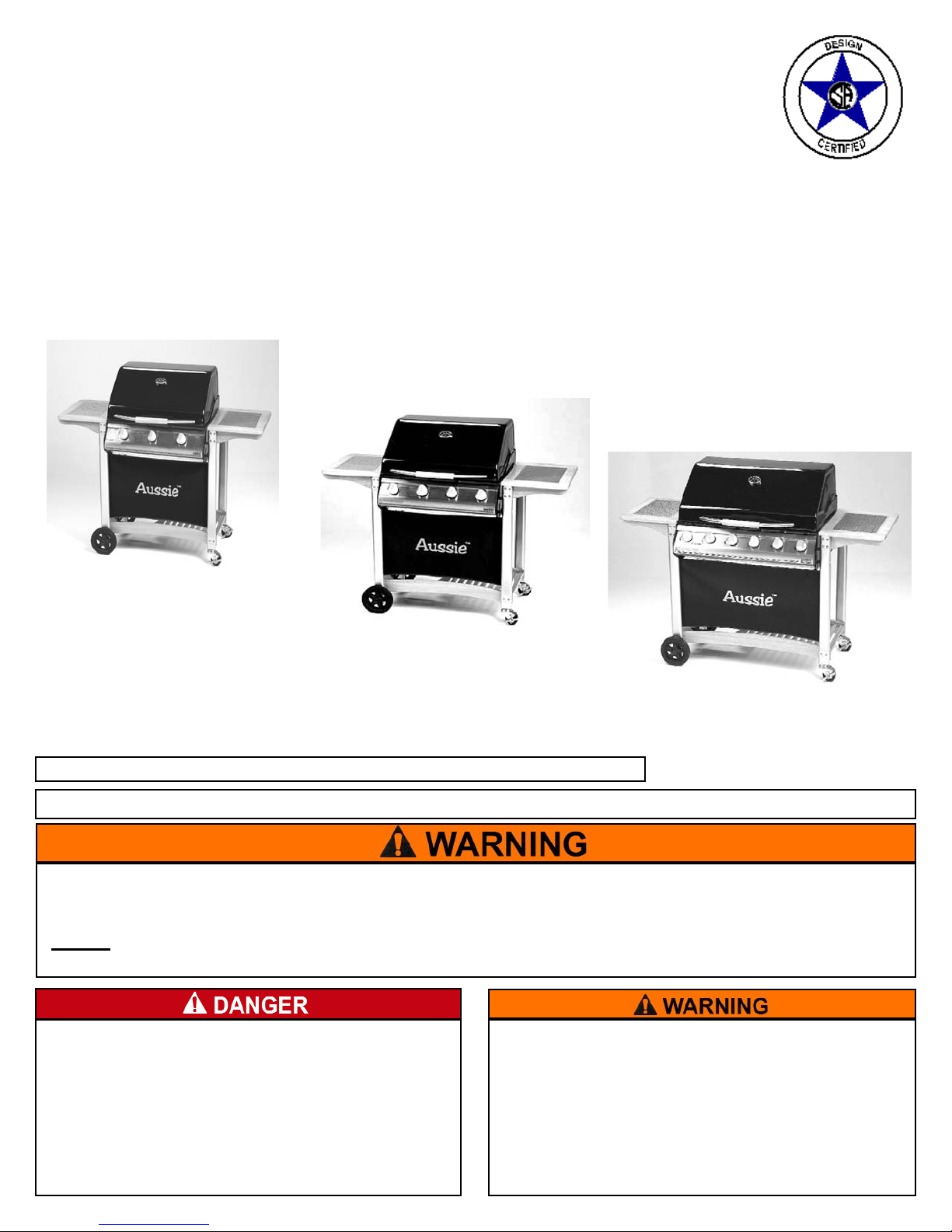
Bonza 3 Elite
Bonza 6 Elite
Bonza 4 Elite
2
I. Assembly Instructions.......................................................2
Parts Illustrations................................................................3
Step 1) Legs/Side Table Assy.............................................5
Step 2) Install LP Cylinder Storage Guard .........................6
Step 3) Assemble Bottom Shelf to Legs.............................7
Step 4) Assemble Wheels, Casters, and LP.........................
Cylinder Support.....................................................8
Step 5) Assemble Grill Body to Cart...................................9
Step 6) Install Control Knobs, Fabric Panel and Hood........
Handle............................................................10
Step 7) Install Bottom Panel and Grease Tray...................11
Step 8) Install Flame Diffuser............................................12
Step 9) Install Cooking Grids............................................12
II. Connecting/Disconnecting the Gas..................................13
A) Using Gas...................................................................13
B) LP Gas Cylinder.........................................................13
C) LP Hose & Regulator.................................................13
1) Connecting LP Gas Cylinder...................................13
2) Disconnecting LP Gas Cylinder..............................14
III. Operating and Maintaining Your LP Gas Grill.................14
A) Before Using Your Grill...............................................14
B) Installation Codes.......................................................14
C) Selecting a Location...................................................14
D) Performing a Leak Test..............................................14
E) Lighting Using the Ignitor...........................................15
F) Manual Lighting the Grill............................................16
G) Check your Flame......................................................17
IV. Grill Cooking...................................................................17
A) Warming Rack............................................................17
B) Roasting Hood Cooking.............................................17
C) Operating the Gas Grill...............................................17
D) End of Cooking Session............................................18
V. Care and Maintenance....................................................18
A) Cleaning the Grill........................................................18
B) Cleaning the Burners.................................................18
C) Storage.......................................................................20
VI. Troubleshooting..............................................................21
VII. Important Notice-LP Cylinder with OPD.........................23
VIII. Limited Warranty.............................................................24
©Meco Corporation
®
2007
— NOTICE —
MECO CORPORATION STRIVES TO BE A QUALITY SUPPLIER OF CONSUMER PRODUCTS. IF
WE OMITTED ANY PARTS NEEDED FOR ASSEMBLY, OR YOU NEED TROUBLESHOOTING
INFORMATION, PLEASE CONTACT US USING OUR TOLL FREE NUMBER. THANK YOU FOR
PURCHASING A MECO CORPORATION PRODUCT.
1-(800)-251-7558
8 am - 5 pm E.S.T Mon. - Fri.
1-(423)-639-1171 (TELEPHONE)
1-(423)-639-2570 (FAX)
CUSTOMER SERVICE DEPARTMENT
MECO CORPORATION
1500 INDUSTRIAL ROAD
GREENEVILLE, TN. 37745 USA
www.aussiegrill.com
CONTENTS
To reduce the risk of serious bodily injury or death:
·The use of alcohol, prescription or non-prescription
drugs could impair the consumer’s ability to properly
assemble or safely operate this appliance.
·Do not connect LP cylinders until assembly is complete.
ASSEMBLY INSTRUCTIONS
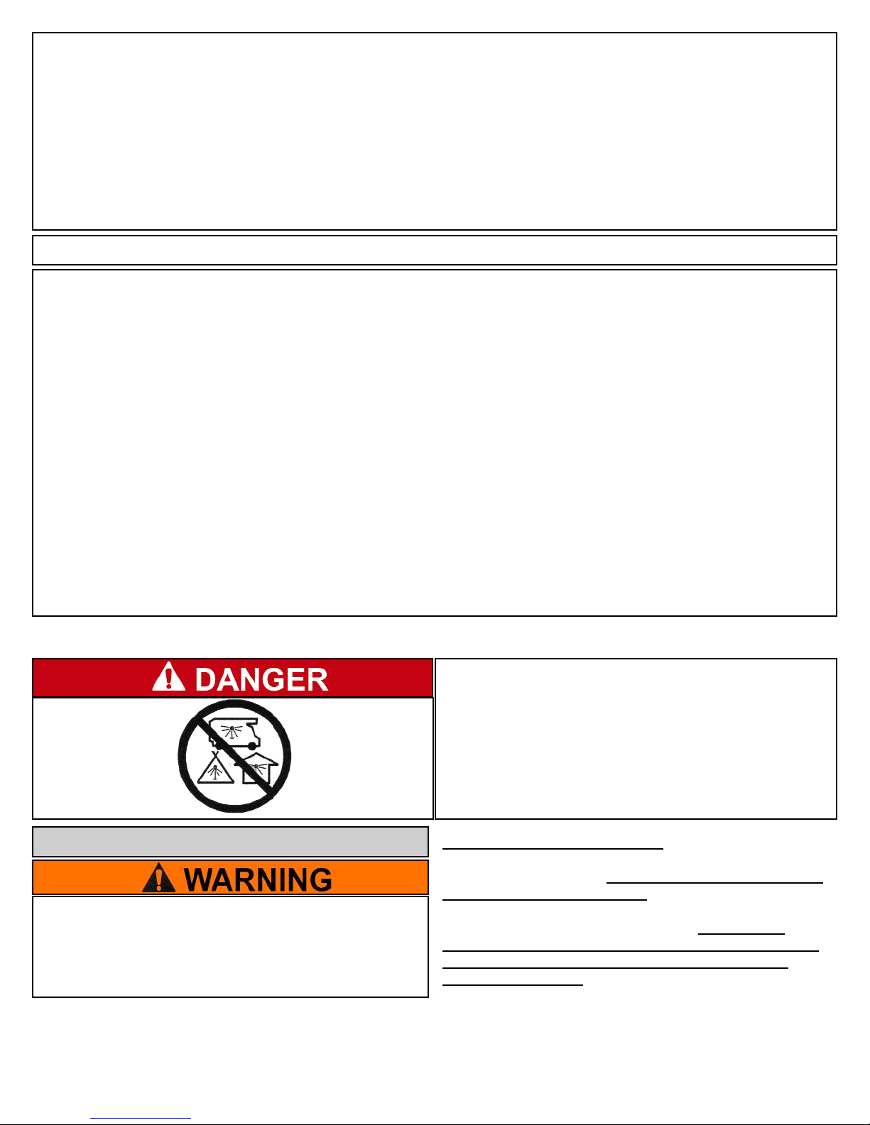
CARBON MONOXIDE HAZARD
This appliance can produce carbon monoxide
which has no odor.
Using it in an enclosed space can kill you.
Never use this appliance in an enclosed space,
such as a camper, tent, car or home.
PREPARATION FOR ASSEMBLY: Remove Grill and all the
packaging from carton and place on floor. Make sure there
are no loose parts. Note: Before using your grill, read the
instructions and your manual. For easier set-up and
assembly, follow instructions of each step in the order they
are written as you look at the diagrams. If accessories
mentioned in certain assembly steps do not come with your
model, skip that step and proceed to the next step that
applies to your model.
3
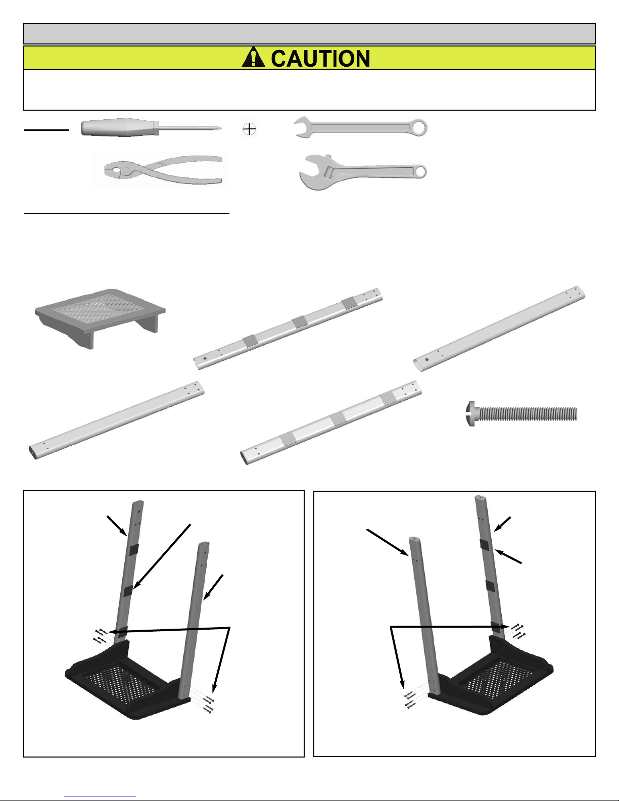
STEP 1) Legs/Side Table Assembly:
Attach the Wheel and Caster Legs to the Side Tables with 1/4-20 x 1-3/8” Bolts through the legs
into threaded insert in side tables. Position legs exactly as shown. Do not completely tighten
bolts.
Wheel Legs and Side Table Assembly
To reduce the risk of injuries:
· Wear protective gloves when handling parts that have sharp edges to prevent cuts.
· Some assembly may require help from another person to prevent handling or lifting injury. Observe where noted.
TOOLS:
(2) Side Table
2 pcs.
(6) RightFront Caster Leg
(3) LeftFront WheelLeg
Left Rear Wheel Leg
ASSEMBLY INSTRUCTIONS
Velcro patches
towards inside
Velcro patches
towards inside
FIG. 1A
FIG. 1B
(5) Right Rear
Caster Leg
(6) Right Front
Caster Leg
(3) Left Front
Wheel Leg
(4) Left Rear
Wheel Leg
(7) 1/4-20 X 1-3/8”
Bolt
(7) 1/4-20 X 1-3/8”
Bolt
(7) 1/4-20 X 1-3/8” Bolt
16 pcs
Caster Legs and Side Table Assembly
(5) Right Rear Caster Leg
and/or
4
(9) Bottom Shelf
1 pc
(8) Bolt, 1/4-20 x 1/2”
2 pc
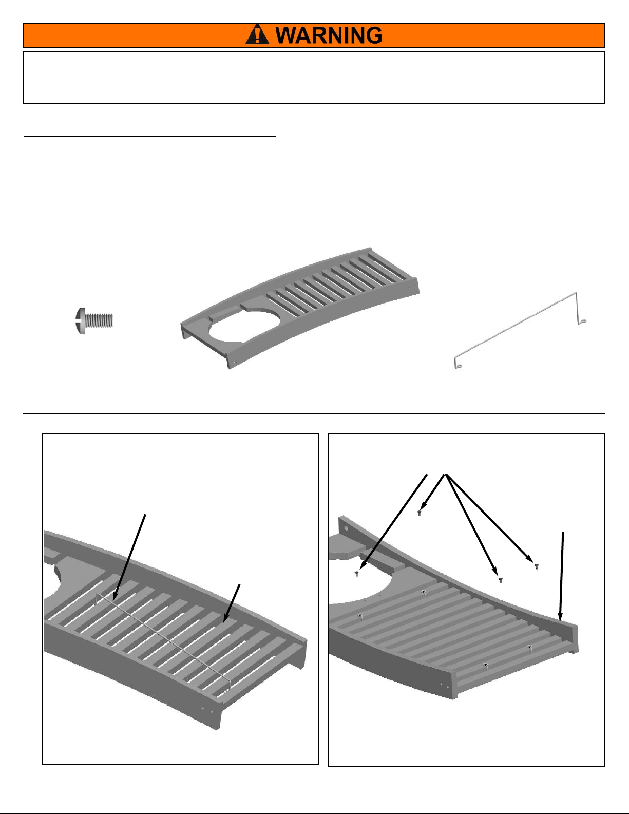
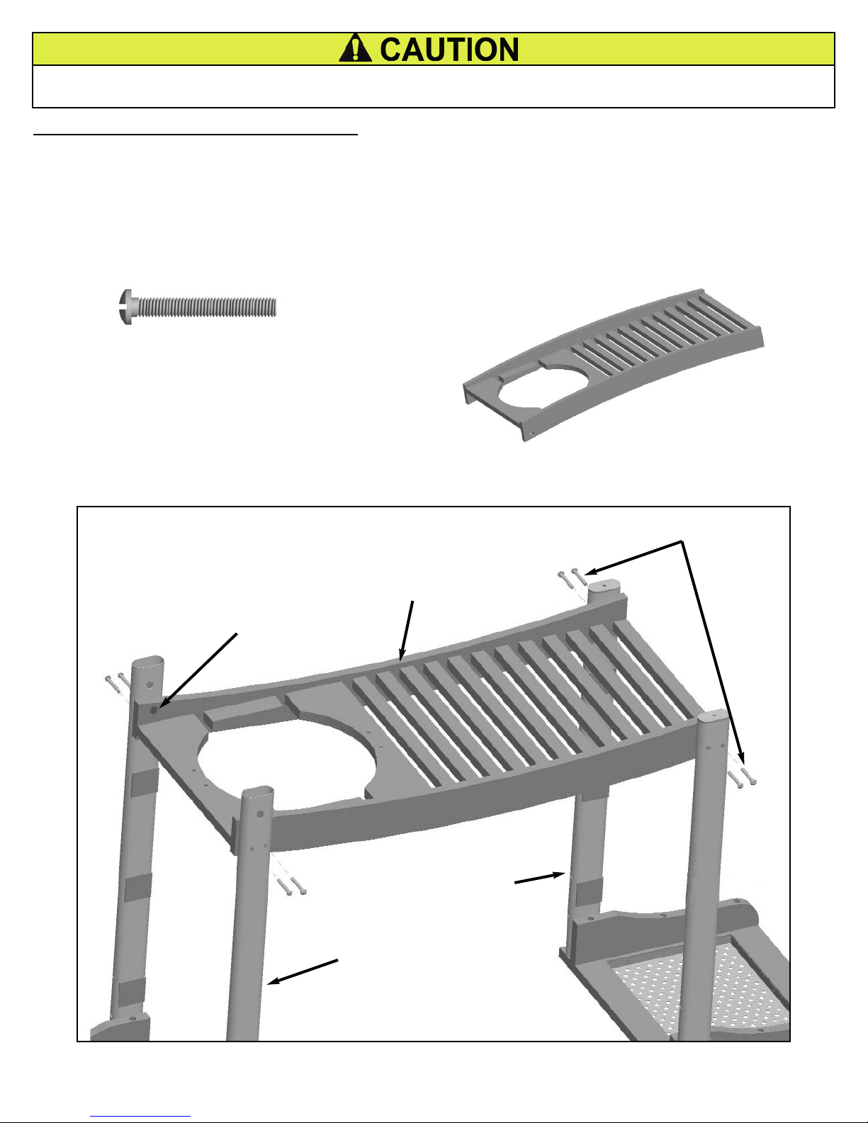
STEP 2) Install LP Cylinder Storage Guard:
Place the LP Cylinder Wire Guard at an angle through the first and second to last openings of the
Bottom Shelf. (FIG. 2A) From the bottom side align the Wire rings with the threaded inserts in the
Bottom Shelf. (FIG. 2B) Install the two 1/4-20 x 1/2” Bolts through the wire rings and tighten.
Repeat these steps for the other Guard.
To reduce the risk of serious bodily injury, fire or death:
· Do not store a spare LP gas cylinder under or near the LP gas grill.
· Do not remove guards or devices to prevent storage of spare cylinder under an LP gas grill.
FIG. 2B
(9) Bottom Shelf
(Top Side)
FIG. 2A
(8) Bolt, 1/4-20 x 1/2”
(9) Bottom Shelf
(Bottom Side)
(10) Cylinder Storage Guard
2 pc
(10) Cylinder
Storage Guard
5
Step 3) Assemble Bottom Shelf to Legs:
• Place the Leg/Side Table/LegAssemblies opposite each other with the velcro patches on same
side. (FIG. 3)
• Place Bottom Shelf upside down inside the Legs. Align the bolt holes of the Bottom Shelf and
Legs. Fasten with the 1/4-20 x 1-3/8” bolts, but do not tighten completely. Note: Do not
align large hole in bottom shelf with axle holes in legs.
(9) Bottom Shelf
1 pc
Note: Do not
Align this Hole
(9) Bottom Shelf
Left Side Table
Leg/Assembly
Right Side
Table/Leg Assembly
FIG. 3
(7) 1/4-20 X 1-3/8” Bolt
8 pc
(7 ) Bolt, 1/4-20 X 1-3/8”
To reduce the risk of injury from handling or lifting:
· Assembly may require help from another person.
6
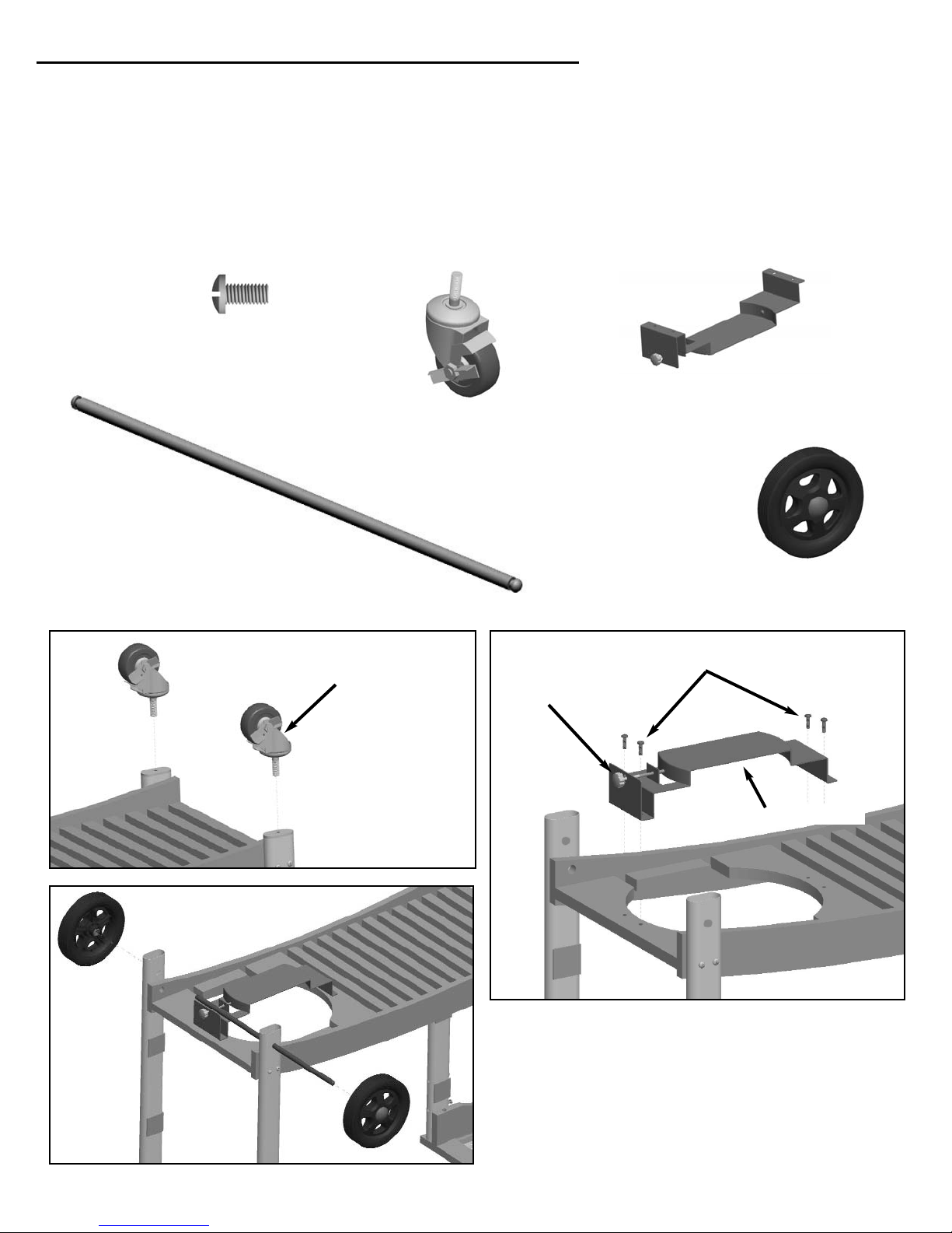
(13) Axle
1 pc
(14) Wheel
Assembly
2 pc
(11) Caster Wheel
2 pc
Step 4) Assemble Wheels, Casters, and LP Cylinder Support:
• Thread Caster Wheels into the Right Side Legs and tighten securely using a 3/4” wrench or
socket. (FIG. 4A)
• Place Cylinder Support on bottom side of Cart Assembly with Cylinder Lock Bolt towards the
end of the Cart Assembly. (FIG. 4B). Secure with four (8) 1/4”-20 x 1/2” Bolts.
• Slide Axle through large holes in the Left Side Wheel Legs. Press the Wheel Assemblies onto
each end of the Axle until the spring clip locks into place. (FIG. 4C)
FIG. 4C
FIG. 4B
FIG. 4A
Cylinder Lock Bolt
(12) Cylinder Support
(8) Bolt, 1/4-20 x 1/2”
Place wrench
inside here to
tighten
(8) Bolt, 1/4-20 x 1/2”
4 pc
(12) Cylinder Support
1 pc
7
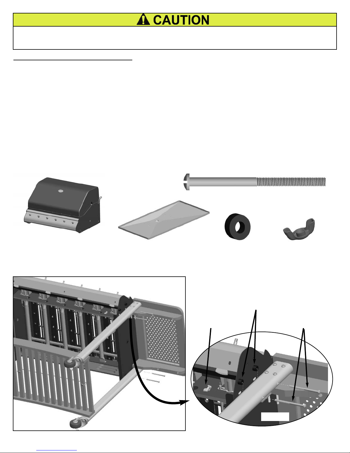
(16) Bottom Body Panel
1 pc
(15) Grill Body
1 pc
(18) Spacer
8 pc
(19) Wingnut, M6
8 pc
Step 5) Assemble Grill Body to Cart:
• Remove the Bottom panel from the Grill Body.
• Lay Grill Body on its back with the control panel facing up. Place Cart Assembly Legs around
the Grill Body. (FIG. 5A)
• Align slotted holes on sides of Grill Body with holes in edges of legs. (FIG. 5B) Hold spacers
between leg and body and insert M6 x 90 bolt through leg, spacer, and slotted hole in Grill
body. Attach M6 Wingnut, but do not tighten. Repeat assembly for three remaining legs.
• With the help of a second person, lift the Grill into the upright position. Grill body should slide
down into slotted holes and seat itself. If not, loosen the wingnuts and push down on the
corners of the body.
• Tighten all bolts and wingnuts. Also tighten all Bottom Shelf and Side Table bolts. Rotate the
Lock lever on the Caster wheels to lock or unlock as desired.
(17) Screw, M6x90mm
8 pc
FIG. 5B
FIG. 5A
(19) Wingnut, M6
(18) Spacer
(17) Screw, M6x90mm
To reduce the risk of injuries:
· Wear protective gloves when handling parts that have sharp edges to prevent cuts.
· This assembly may require help from another person to prevent handling or lifting injury.
8
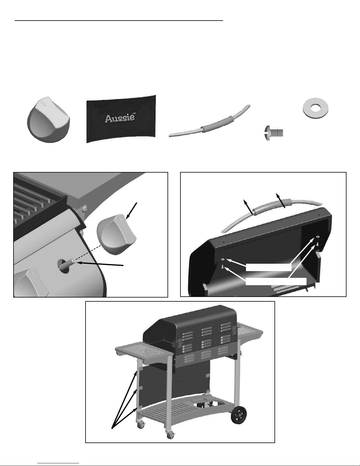
Step 6) Install Control Knobs, Fabric Panel, and Hood Handle:
• Align the flat keyed hole in the Control Knobs with the keyed stem of the Control valves. Push
the Control Knobs onto the Valve stem. (FIG. 6A)
• Open the Hood and position the handle with the bolt heads facing up. Align the threaded holes
in the handle with the two holes in the hood. Secure using two M6 x 10 Bolts and two M6
Washers. ( FIG. 6B)
• Attach the Fabric Panel by aligning it with the curved edge of the Lower Shelf and pressing it
against the velcro patches on each side of the front legs. (FIG. 6C)
(21) Fabric Panel
1 pc
(22) Handle
1 pc
FIG. 6C
(23) Bolt, M6 x 10mm
2 pc
(20) Control Knob
4 pc
FIG. 6A
FIG. 6B
Velcro Patches
(23) M6 x 10mm Bolt
Valve Stem
Handle bolt heads facing up
(20) Control
Knob
(24) Washer, M6
2 pc
(24) M6 Washer
 Loading...