

Aussie Adventurer 2400, Adventurer 2410, Adventurer 2430, Adventurer 2420, Adventurer 2440 Owner & User Manual
FOR YOUR SAFETY
If you smell gas:
1. Do not attempt to light appliance.
2. Extinguish any open flame.
3. Disconnect from fuel supply.
FOR YOUR SAFETY
1. Do not store or use gasoline or other
flammable vapors and liquids within 25 feet
(7.62m) of this or any other appliance.
2. An LP cylinder not connected for use shall not
be stored within 10 feet (3.05m) in the vicinity
of this or any other appliance.
3. Do not store any LP gas cylinder indoors.
For Customer Service, call 1-800-251-7558 or visit our website at www.meco.net
FOR OUTDOOR HOUSEHOLD USE ONLY. NOT FOR COMMERCIAL USE.
• Failure to follow these instructions could result in fire or explosion which could cause death,
serious personal injury, or property damage.
• Read and follow instructions carefully before assembly or use.
• Do not
use this product for any other purpose than which it is intended.
• These instructions must be kept with the user. SAVE THESE INSTRUCTIONS.
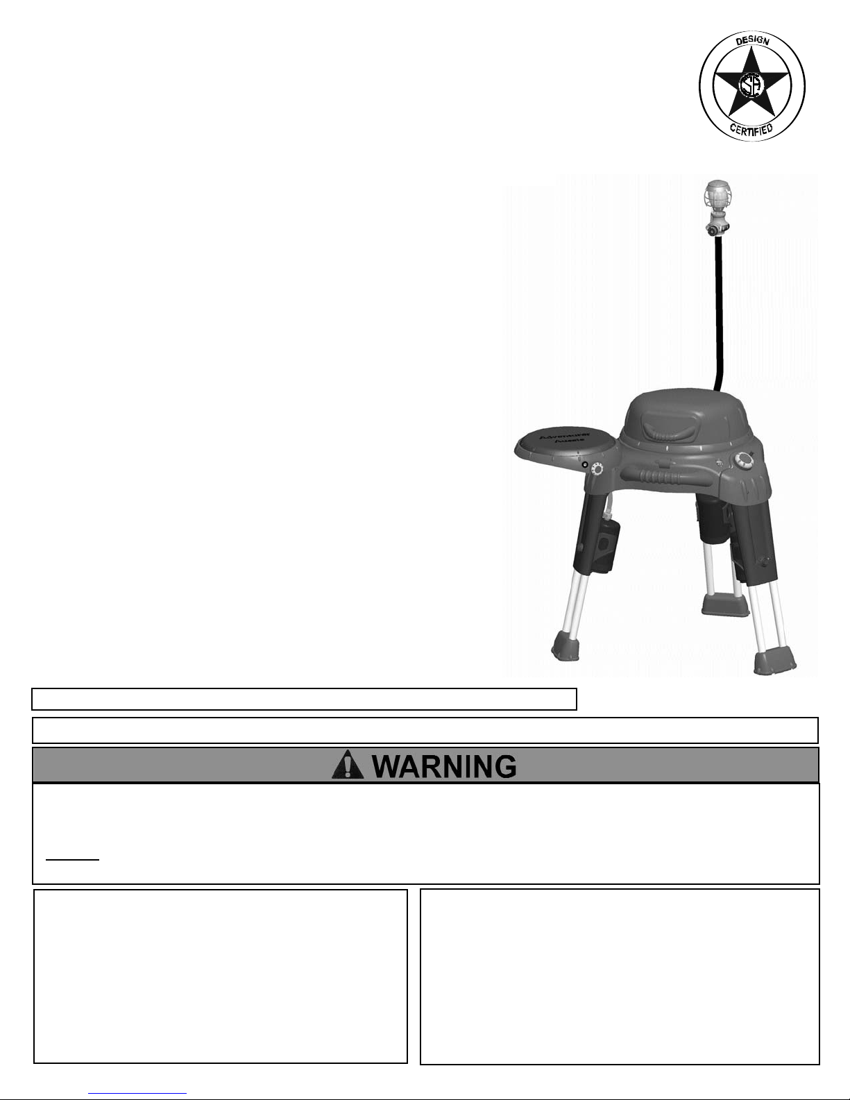
Aussie Adventurer
TM
MODEL 2430 shown
This Owners Manual for use with Models:
2400 with Side Table
2410 with Side Burner
2420 with Side Table and Lantern
2430 with Side Burner and Lantern
2440 with Side Burner, Lantern and Carry Bag
(LP Cylinders not included)
PORTABLE LP Gas Grill
Pre-Assembled Grill
Owner’s and Use Manual
I. Assembly Instructions.......................................................2
A) Parts Illustrations...........................................................3
B) Parts List........................................................................4
C) Setting up Your Grill.......................................................5
1) Standing Grill On Legs...............................................5
2) Side Table Assembly..................................................7
3) Side Burner Table Assembly.....................................7
4) Lantern Assembly......................................................8
a) Assemble Mantle to Burner....................................8
b) Pre-burn Mantle.....................................................8
c) Assemble Lantern to Gas T ube..............................9
d) Assemble Lantern/Gas T ube to Grill.......................9
5) Install Grease Container ............................................9
D) Connecting/Disconnecting LP Cylinder.......................10
1) Installation Codes....................................................10
2) LP Cylinder..............................................................10
3) Hoses & Regulator...................................................10
II. Operating and Maintaining Your LP Gas Grill...............11
A) Before Using Your Grill..............................................11
1) Using Gas................................................................11
2) Selecting a Location...............................................11
3) Performing a Leak Test............................................12
B) Lighting the Gas Grill.................................................13
1) Ignition Lighting Main Grill........................................13
2) Manual Lighting Main Grill........................................13
3) Ignition Lighting the Side Burner..............................14
4) Manual Lighting the Side Burner.............................14
5) Ignition Lighting the Lantern ...................................15
6) Manual Lighting the Lantern ...................................15
7) Check Your Flame...................................................15
C) Operating the Gas Grill..............................................16
1) Grill Cooking............................................................16
2) End of Cooking Session..........................................17
D) Care and Maintenance...............................................17
1) Cleaning the Grill.....................................................17
a) Grease Container ... ............................................17
b) Cooking Grid.......................................................17
c) Hood and Bowl....................................................17
d) Burners................................................................17
2) Storage and Transport............................................19
III. Troubleshooting...............................................................20
V. Limited Warranty..............................................................22
©Meco Corporation
®
2005
— NOTICE —
MECO CORPORATION STRIVES TO BE A QUALITY SUPPLIER OF CONSUMER PRODUCTS. IF
WE OMITTED ANY PARTS NEEDED FOR ASSEMBLY, OR YOU NEED TROUBLESHOOTING
INFORMATION, PLEASE CONTACT US USING OUR TOLL FREE NUMBER. THANK YOU FOR
PURCHASING A MECO CORPORATION PRODUCT.
1-(800)-251-7558
8 am - 6 pm E.S.T Mon. - Fri.
1-(423)-639-1171 (TELEPHONE)
1-(423)-639-2570 (FAX)
CONSUMER SERVICE DEPARTMENT
MECO CORPORATION
1500 INDUSTRIAL ROAD
GREENEVILLE, TN. 37745 USA
www.meco.net
To reduce the risk of serious bodily injury or death:
·The use of alcohol, prescription or non-prescription
drugs could impair the consumer’s ability to properly
assemble or safely operate this appliance.
·Do not connect LP cylinders until assembly is complete.
CONTENTS
ASSEMBLY INSTRUCTIONS
CARBON MONOXIDE HAZARD
This appliance can produce carbon monoxide
which has no odor.
Using it in an enclosed space can kill you.
Never use this appliance in an enclosed space,
such as a camper, tent, car or home.
PREPARATION FOR ASSEMBLY: Note: This Grill is
pre-assembled. Only the accessary items need to be
attached.Remove Grill and all the packaging from carton and
place on floor. Make sure there are no loose parts. Note:
Before using your grill, read the instructions and your
manual. For easier set-up assembly, follow instructions of
each step in the order they are written as you look at the
diagrams. If your model grill does not have the accessories
indicated in the assembly steps, skip that step and proceed to
the next step that applies to your model.
If you need replacement parts, look in the Parts List Section
to find the exact parts you need. If you have any questions or
need help, contact our Customer Service. Be sure to mention
the grill model number located on right side of the grill body.
2

3
Parts Replacement Illustrations
1
2
26
10
9
7
35
36
23
8
14
3
5
6
12
15
13
38
19
20
25
27
28
31
34
40
41
42
29
37
30
33
24
11
4
32
39
16
21
17
22
18

PARTS LIST
ITEM DESCRIPTION PART #
1 Owner's Manual 03.6506.00 1 1 1 1 1
2 Hood w/Hinges 03.6506.01 1 1 1 1 1
3 Screw, M6x9 Shoulder (Hood Hinge) 03.6506.02 2 2 2 2 2
4 Hinge, Hood 03.6506.03 1 1 1 1 1
5 Screw, M5x10mm (Hood Hinge Bracket) 03.6237.00 3 3 3 3 3
6 Nut, M5 Hex Washer Head ( Hood Hinge) 03.6506.04 3 3 3 3 3
7 Screw, M5x15 (Hood Handle) 03.6506.05 2 2 2 2 2
8 Hood Handle 03.6506.06 1 1 1 1 1
9 Hood Badge 03.6506.07 1 1 1 1 1
10 Hood Latch 03.6506.08 1 1 1 1 1
11 Screw, M5x12mm (Upper Leg) 03.6506.09 6 6 6 6 6
12 Bracket, Leg 03.6506.10 3 3 3 3 3
13 Screw, ST4.8 x 25mm Type A (Leg Brack et ) 03.6506.11 9 9 9 9 9
14 Assy, Leg Bracket Assy 03.6506.12 3 3 3 3 3
15 Assy, Leg 03.6506.13 3 3 3 3 3
16 Screw, ST4.8x10mm Type B (Leg/Bowl Bracket) 03.6506.14 20 20 20 20 20
17 Screw, ST4.8x10mm Type A (Leg Lock) 03.6506.15 6 6 6 6 6
18 Leg Lock 03.6506.16 3 3 3 3 3
19 Leg Foot 03.6506.17 3 3 3 3 3
20 Screw, ST4.8x45mm Type B (Leg Foot) 03.6506.18 3 3 3 3 3
21 Bowl Pan 03.6506.19 1 1 1 1 1
22 Post Support, Bowl Pan 03.6506.20 4 4 4 4 4
23 Grease Container 03.6506.21 1 1 1 1 1
24 Cooking Grid 03.6506.22 1 1 1 1 1
25 Bracket, Body Hinge Brack et 03.6506.23 1 1 1 1 1
26 Body/Leg Assembly 03.6506.24 1 1 1 1 1
27 Screw, M6x15mm (Body Carry Handle) 03.6506.25 2 2 2 2 2
28 Handle, Body Carry 03.6506.26 1 1 1 1 1
MODEL
2440
QTY
MODEL
2400
MODEL
2410
MODEL
2420
MODEL
2430
4
53
54
46
48
44
47
49
51
55
59
50
52
56
57
60
58
62
45
43
61
PARTS LIST (CONT'D)
ITEM DESCRIPTION PART #
29 Heat Shield 03.6506. 27 1 1 1 1 1
30 Screw, ST3.8x6mm (Heat Shield) 03.6506.28 2 2 2 2 2
31 Guide Bracket, Main Burner 03.6506.29 1 1 1 1 1
32 Screw, M4x10mm (M. Burner/S. Burner Electrode) 03.6506.30 4 4 4 4 4
33 Main Burner 03.6506.31 1 1 1 1 1
34 Wire, Main Burner Ground 03.6506.32 1 1 1 1 1
35 Nut, M4 Hex (Main Burner/Ground W ire) 03.6506.33 2 2 2 2 2
36 Piezo 03.6260.01 1 2 1 2 2
37 Electrode, Main Burner 03.6506.34 1 1 1 1 1
38 Knob, Main Burner 03.6506.35 1 1 1 1 1
39 Valve/Hose/Regulator, Main burner 03.6506.36 1 1 1 1 1
40 Level Vial 03.6506.37 1 1 1 1 1
41 Side Table Accessory 03.6506.38 All All All All All
42 Grid, Side Burner 1210.5.001 ---- 1 ---- 1 1
43 Side Burner/Table Accessory (Replacement) 1220.5.001 All All All All All
44 Cover, Side Burner/Table 03.6506.39 ---- 1 ---- 1 1
45 Knob, Side Burner 03.6506.40 ---- 1 ---- 1 1
46 Screw, M3.5x8mm Torx (Side Burner Valve) 03.6506.41 ---- 2 ---- 2 2
47 Valve Assembly, Side Burner 03.6506.42 ---- 1 ---- 1 1
48 Pin, Cotter 1.6mmx28mm ( Side Bur ner Valve) 03.6235.00 ---- 2 ---- 2 2
49 Electrode, Side Burner 03.6506.43 ---- 1 ---- 1 1
50 Burner, Side 03.6506.44 ---- 1 ---- 1 1
51 Lantern Gas Tube 03.6506.45 ---- ---- 1 1 1
52 Lantern 03.6506.46 ---- ---- 1 1 1
53 Cover, Lantern Top 03.6506.47 ---- ---- 1 1 1
54 Globe, Lantern 03.6506.48 ---- ---- 1 1 1
55 Mantle, Lantern 03.6506.49 ---- ---- 2 2 2
56 Screw, #10x3/4" Type 25 Csk (Lantern Knob) 03.6506.50 ---- ---- 1 1 1
57 Knob, Lantern 03.6506.51 ---- ---- 1 1 1
58 Screw, #4-24x3/8" Type 25 (Lantern Housing) 03.6506.53 ---- ---- 2 2 2
59 Electrode/Piezo, Lantern 03.6506.54 ---- ---- 1 1 1
60 Pushbutton, Lantern 03.6506.55 ---- ---- 1 1 1
61 Lantern/Gas Tube Accessory 1230.5.001 All All All All All
62 Carry Bag Accessory 1240.5.001 All All All All All
QTY
MODEL
2400
MODEL
2410
MODEL
2420
MODEL
2430
MODEL
2440
SETTING UP YOUR GRILL
Fig. 1
Release Hood Latch
Level Indicator
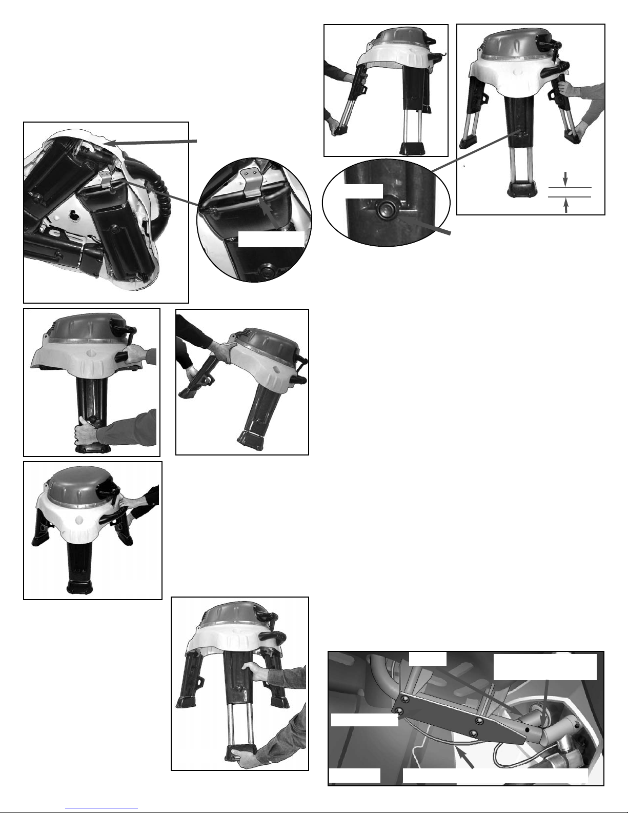
STANDING GRILL ON LEGS
STEP 1) With your grill flat on the floor, release the
Hood latch from the Hood Handle. (FIG. 1) Open
Hood and remove any accessories from the grid
that are with your model. Do not remove anything
else at this step. Close and re-latch the hood.
To reduce the risk of a cut or pinching injury:
· Wear protective gloves when handling parts that have
sharp edges.
· When opening legs, keep hands and fingers away from
the three body leg mount areas to avoid pinching. (See
FIG. 2A)
5
6
FIG. 2B
STEP 2) Lift grill up at one leg mount. Release the
spring lever at each leg foot. (FIG. 2A) Swing each
leg all the way out one at a time, and let it rest on
the floor. (FIG. 2B, 2C & 2D) The last leg will allow
the grill to stand by itself. This is the lower height
for use.
STEP 3) To use the grill
at the full height, slide
the legs out one at a
time until they stop. You
do not have to use the
leg adjustment for full
leg extension. (FIG. 3A,
3B & 3C)
Depress Leg Button
Fig. 3A
FIG. 3C
FIG. 3B
STEP 4) If the grill is not standing level, the legs
can be adjusted to level it. There are 3 adjustments
within a range of 1 1/4” from the fully extended leg
in which to level the grill.
While supporting the grill, depress the round leg
button with your thumb on the leg or legs that need
to be adjusted. (FIG. 3C & 3D) Slide the leg in or
out until you find the setting that best allows leveling. You will hear a light click at each setting when
extending the leg. Check the grill level by the level
indicator located to the left of the Main Grill control
knob. (See FIG. 1 page 5)
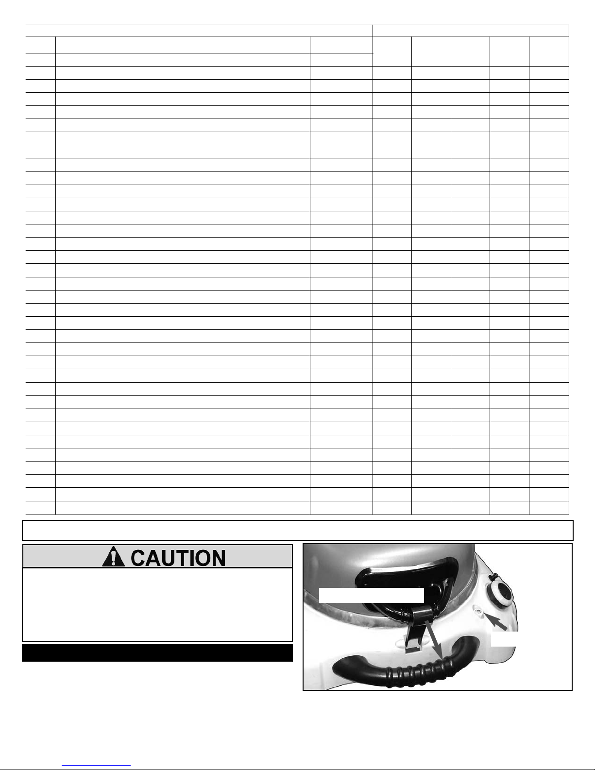
STEP 5) Unlatch the hood and remove the Grid.
Disconnect the Electrode wire underneath the bowl.
(FIG. 4A) At a point directly opposite the control
knob, lift up the Bowl Pan and burner and remove
from the grill. (FIG. 4B) Remove the styrofoam pads
inside the bowl area and any that fall toward the
middle. Remove any other accessories that may be
packed inside. Reinstall the Bowl Pan. Insert the
burner tube and electrode wire through the hole in
body. The burner guide should engage the burner
tube over the valve nozzle. Check visually to make
sure it does engage. Reconnect the electrode wire.
Replace the Cooking Grid. (See page 16)
FIG. 3D
FIG. 2D
FIG. 2C
Spring Lever
FIG. 2A
1 1’4”
Leg Pinch area
Disconnect Electrode Wire from Ignitor
FIG. 4A
Ignitor
Burner guide
Burner tube engaged
over valve nozzle
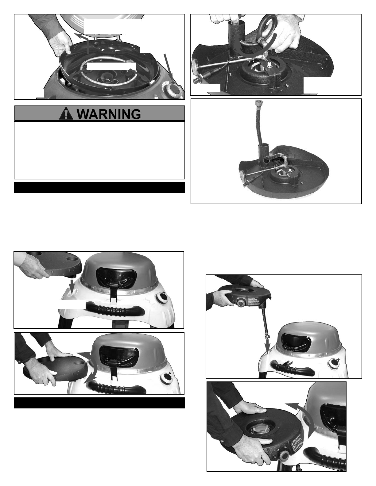
Insert the tubular collar into the left leg PTO
TM
(Propane Take-OffTM) opening of the grill until the
Side Table rests snugly against the grill body.
(FIG. 4A & 4B) Rotate the Side Table back and
forth slightly to make sure it is resting solidly. Do
not apply excessive force.
FIG. 4A
Insert Collar into PTO
TM
STEP 1) Turn Side Burner Table upside down.
(FIG. 5A) Pull the hose away from the side burner
table flange. Pull threaded coupling end out of
collar while feeding the hose through hole in the
side of the collar. Pull the hose until the loop is
taken out and hose is extended out of the collar.
(FIG. 5B)
FIG. 4B
FIG. 5B
FIG. 5C
FIG. 5D
STEP 2) Turn the Side Burner Table right side up
and insert the hose end through the left leg PTO
TM
opening of the grill. (FIG. 5C) Push the Side Burner
Table down until the collar rests on the internal
stop. (FIG. 5D) Rotate the Side Burner Table back
and forth slightly to make sure it is resting solidly.
Do not apply excessive force.
Insert Hose
into PTO
TM
SIDE TABLE ASSEMBLY
To reduce the risk of serious bodily injury or death:
· Do not load plastic side table or side burner with more
than 10 lb./4.5kg (one gallon liquid/3.8L). Excess weight
could tip grill over causing a fire or explosion and
damage side table or side burner.
· Do not place hot utensils or cookware on plastic side
table or side burner cover that can cause them to melt.
SIDE BURNER ASSEMBLY
FIG. 5A
Pull hose away
from flange
Stryofoam Pads
Control Knob
Fig. 4B
Lift Bowl Pan and
Burner up and out
7
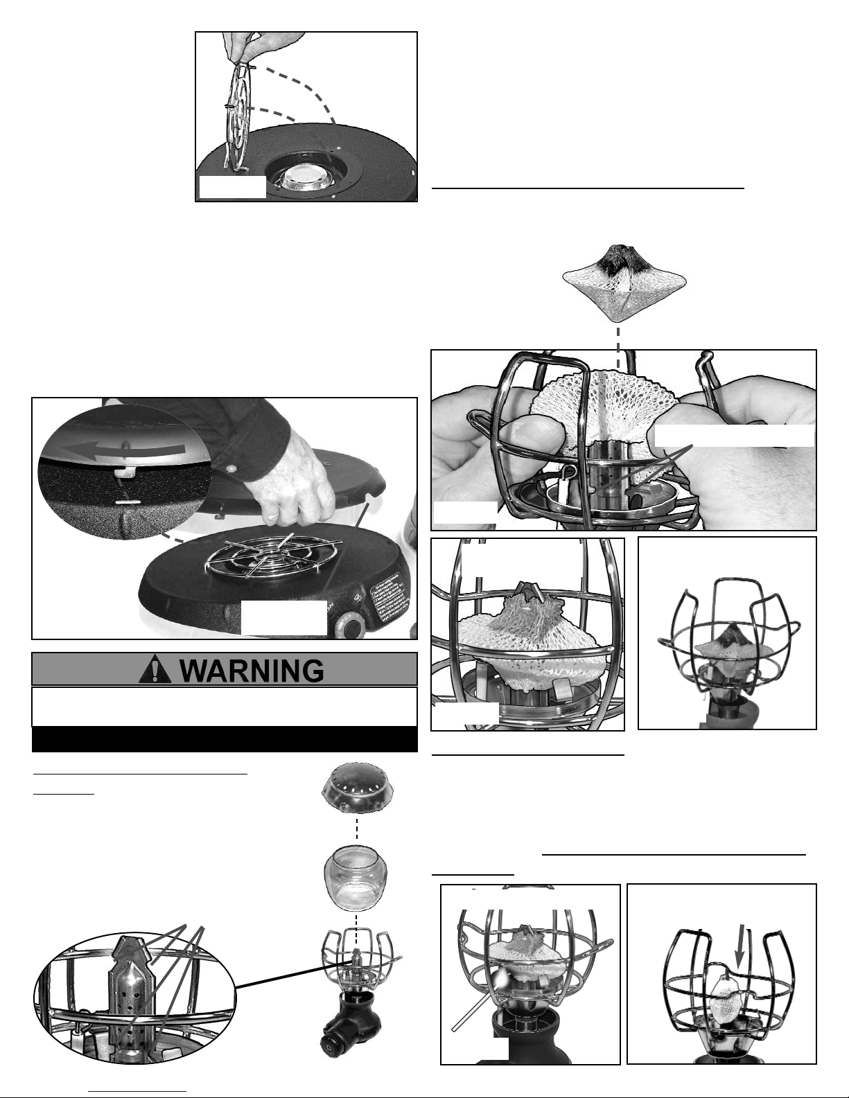
STEP 3) Hook Side
Burner Grid into far
left hole in side table
and lower two wires
into the other two
holes. (FIG. 5E)
FIG. 5E
STEP 4) Your Side Burner can be used as a Side
Table when not using the Side Burner. Locate the
3-hooks of the polyethylene Side Burner Cover
over the 3-slots on the side burner edge. (FIG. 5F)
Push the 3-hooks into the slots. Lock cover by
rotating clockwise with the two finger hole notches
opposite each other on the cover. The finger hole
notches are also used for unlocking and removing
the cover.
FIG. 5F
Finger hole
notch
8
STEP 2) Pre-burn Mantle: Use a match to light the
mantle the first time. (Note: Mantle will burn
without gas.) (FIG. 6E) Let the mantle burn until it
shrinks to a bulb shape and turns white. (FIG. 6F)
Allow the Lantern to cool; then replace the globe
and top cover. Do not touch the mantle or it will be
destroyed.
FIG. 6B
Bottom Burner notches
Mantle pulled
over notches
FIG. 6C
FIG. 6D
Mantle in
conical shape
STEP 1) Assemble Mantle to
Lantern: Place Lantern on a table.
(You may sit down for this step.) Lift
the Lantern top cover off and
remove the glass globe. (FIG. 6A)
Assemble mantle over the top and
bottom burner notches.
Light Mantle with match
FIG. 6E
Insert the large opening of the Mantle over the
burner. (FIG. 6B) NOTE: The colored end should
be at the top. Pull the mantle down over the burner
until the large opening encircles the two bottom
burner notches and the top opening encircles the
two top burner notches. (FIG. 6C) Form the mantle
to a conical shape around the burner. (FIG. 6D)
NOTE: Do not tear a hole in the mantle.
If you
do, use another one. Always have spare mantles
handy. (See Warnings page 15.)
FIG. 6A
LANTERN ASSEMBLY
Top and Bottom Burner Notches
· Use Lantern only with a 1 pound LP cylinder. Do not
attempt to connect to any other size cylinders.
FIG. 6F
Mantle shrinks to bulb
shape and turns white
 Loading...