

Aussie 8452-5-sl1, 8452-5-s11, 8452-5-ss1 Owner's Manual

For Customer Service, call 1-800-251-7558 or visit our web site at www.meco.net
FOR OUTDOOR HOUSEHOLD USE ONLY. NOT FOR COMMERCIAL USE.
• Failure to follow these instructions could result in fire or explosion which could cause death,
serious personal injury, or property damage.
• Read and follow instructions carefully before assembly or use.
• Do not
use this product for any other purpose than which it is intended.
• These instructions must be kept with the user. SAVE THESE INSTRUCTIONS.
MODELS: 8452-5-SS1 Liquid Propane
8452-5-SL1 Liquid Propane
DANGER
If you smell gas:
1. Shut off gas to the appliance.
2. Extinguish any open flame.
3. Open lid.
4. If odor continues, keep away from the
appliance and immediately call your gas
supplier or your fire department.
Assembly and Use Manual
ULURU
TM
LP Gas Grill
Elite
MODEL 8452-5-S11 Liquid Propane
Aussie
®
WARNING
1. Do not store or use gasoline or other
flammable vapors and liquids in the vicinity
of this or any other appliance.
2. An LP cylinder not connected for use shall
not be stored in the vicinity of this or any
other appliance.
bbyy MMeeccoo
®
© MECO CORPORATION®2006
— NOTICE —
MECO CORPORATION STRIVES TO BE A QUALITY SUPPLIER OF CONSUMER PRODUCTS. IF
WE OMITTED ANY PARTS NEEDED FOR ASSEMBLY, OR YOU NEED TROUBLESHOOTING
INFORMATION, PLEASE CONTACT US USING OUR TOLL FREE NUMBER. THANK YOU FOR
PURCHASING A MECO CORPORATION PRODUCT.
1-(800)-251-7558
8 am - 6 pm E.S.T Mon. - Fri.
1-(423)-639-1171 (TELEPHONE)
1-(423)-639-2570 (FAX)
CONSUMER SERVICE DEPARTMENT
MECO CORPORATION
1500 INDUSTRIAL ROAD
GREENEVILLE, TN. 37745 USA
www.meco.net
To reduce the risk of serious bodily injury or death:
·The use of alcohol, prescription or non-prescription
drugs could impair the consumer’s ability to properly
assemble or safely operate this appliance.
·Do not connect LP cylinders until assembly is complete.
ASSEMBLY INSTRUCTIONS
CARBON MONOXIDE HAZARD
This appliance can produce carbon monoxide
which has no odor.
Using it in an enclosed space can kill you.
Never use this appliance in an enclosed space,
such as a camper, tent, car or home.
PREPARATION FOR ASSEMBLY: Remove Grill and all the
packaging from carton and place on floor. Make sure there
are no loose parts. Note: Before using your grill, read the
instructions and your manual. For easier set-up and
assembly, follow instructions of each step in the order they
are written as you look at the diagrams. If accessories
mentioned in certain assembly steps do not come with your
model, skip that step and proceed to the next step that
applies to your model.
If you need replacement parts, look in the Parts List Section
to find the exact parts you need. If you have any questions or
need help, contact our Customer Service. Be sure to mention
the grill model number located on right side of the grill body.
2
I. ASSEMBL Y INSTRUCTIONS............................................2
A) Parts Illustrations...........................................................3
B) Parts List.......................................................................4
Step 1) Cylinder Clamp/Back Panel Assembly..............5
Step 2) Cart Sides and Bottom Assembly.....................6
Step 3) Front Crossbar Assembly..................................6
Step 4) Caster Cart Assembly........................................7
Step 5) Door Assembly...................................................7
Step 6) Hood/Bowl to Cart Assembly.............................8
Step 7) Burner Side Table Assembly..............................9
Step 8) Side Burner Valve Assembly.............................9
Step 9) Side Burner Assembly.....................................10
Step 10) Side Burner Knob/Grid Assembly..................10
Step 11) Burner Removal/Re-Assembly.......................11
Step 12) Foil Pan/Grease Pan/Drip Assembly........... 11
Step 13) Flame Diffuser/Cooking Grid/Warming Rack
Assembly........................................................12
Step 14) Wiring the Ignition Box..................................12
Step 15) Install the Ignition Box...................................12
II. Connect/Disconnect Gas to the Grill................................13
A) Using Gas...................................................................13
B) LP Gas Cylinder...........................................................13
C) LP Hose & Regulator...................................................13
1) Connecting LP Gas Cylinder...................................14
2) Dis-connecting LP Gas Cylinder.............................14
III. Operating and Maintaining Your LP Gas Grill.,................14
A) Before Using Your Grill...............................................14
B) Installation Codes.......................................................14
C) Selecting a Location...................................................14
D) Performing a Leak Test..............................................14
E) Lighting Using Pulse Spark Ignition...........................16
F) Manual Lighting of the Grill......................................17
G) Lighting the Side Burner.............................................17
H) Check your Flame.......................................................17
I) Manual Lighting the Side Burner..................................18
IV. Grill Cooking...................................................................18
A) Warming Rack............................................................18
B) Roasting Hood Cooking.............................................18
C) Operating the Gas Grill...............................................18
D) End of Cooking Session............................................19
V. Care and Maintenance....................................................19
A) Cleaning the Grill........................................................19
B) Storage.......................................................................21
VI. Troubleshooting..............................................................21
VII. Important Notice-LP Cylinder with OPD........................23
VII. Limited Warranty............................................................24
CONTENTS

3
PARTS ILLUSTRATIONS
If you need replacement parts, refer to the Parts Illustrations and the Parts List to find the exact parts you need. If you have
any questions which require help, contact Customer Service and be sure to mention the model number of your grill.
(2) SILVER BACK PANEL
(5) BOTTOM PANEL
SILVER
(6) BOTTOM PANEL
BLACK
(8) M6 NUT
(7) M6 x 15
SCREW
(23) FIXED CASTER
(41) SIDE
BURNER VALVE
(1) OWNERS MANUAL
(4) LP CYLINDER CLAMP
(28) RIGHT DOOR 430 SS
(29) RIGHT DOOR BLACK
(64) RIGHT DOOR SILVER
(21) FRONT CROSSBAR SILVER
(22) FRONT CROSSBAR BLACK
(19) RIGHT SIDE PANEL SILVER
(20) RIGHT SIDE PANEL BLACK
(26) LEFT DOOR 430 SS
(27) LEFT DOOR BLACK
(63) LEFT DOOR SILVER
(13) ST4.0 x
10MM SCREW
(31) BOWL ASSEMBLY
(32) HOOD ASSEMBLY 430/SILVER
(33) HOOD ASSEMBLY 430/BLACK
(42) M5 X 10MM
SCREW
(43) M5 HEX NUT
(25) DOOR HANDLE
(44) SIDE BURNER
(47) CONTROL KNOB
(48) SIDE BURNER GRID
(49) MAIN BURNER
(46) SIDE BURNER
ELECTRODE
(45) M4 X 8MM
SCREW
(14) LEFT SIDE PANEL SILVER
(15) LEFT SIDE PANEL BLACK
(24) SWIVEL CASTER
(30) HOOD/BOWL ASSEMBLY
(SEE 31 & 32 or 33 FOR REPLACEMENT)
(34) HOOD SPRING CLIP
(35) HOOD PIN
(3) BLACK BACK PANEL
(17) M6 x 20 SCREW
(16) MATCHLIGHT
HOLDER & CHAIN
(18) M6 SLEEVE
(36) LEFT SIDE BURNER
TABLE SILVER
(37) LEFT SIDE BURNER
TABLE BLACK
(9) BOTTOM PANEL
BRACE SILVER
(10) BOTTOM PANEL
BRACE BLACK
(38) M4 X 15MM
SCREW
(11) BACK PANEL
BRACE SILVER
(12) BACK PANEL
BRACE BLACK
(39) RIGHT SIDE BURNER
TABLE SILVER
(40) RIGHT SIDE BURNER
TABLE BLACK
(50) MAIN BURNER PIN

(53) DRIP TRAY
(51) FOIL PAN
(54) FLAME DIFFUSER
(63) MANIFOLD ASSEMBLY (LP)
(60) HEAT INDICATOR
PARTS LIST
ITEM DESCRIPTION PART # QTY.
1 Owner's Manual 03.6538.00 1
2 Back Panel-Silver 03.6508.00 1
3 Back Panel-Black 03.6508.01 1
4 LP Cylinder Clamp 03.6510.00 1
5 Bottom Panel-Silver 03.6511.00 1
6 Bottom Panel-Black
03.6511.01
1
7 Screw, M6 x 15 03.6385.00 55
8 Nut, M6 03.6470.00 15
9
Brace, Bottom Panel Silver 03.6513.00
1
10
Brace, Bottom Panel Black 03.6513.01
1
11
Brace, Back Panel Silver
03.6514.00 1
12
Brace, Back Panel Black
03.6514.01 1
13 Screw, ST4.0 x 10mm 03.6223.00 9
14 Left Side Panel Silver 03.6515.00 1
15 Left Side Panel Black 03.6515.01 1
16 Match Light Holder & Chain 03.6516.00 1
17 Screw, M6 x 20 03.6517.00 1
18 Sleeve, M6 x20 Bolt (Match Light Hanger) 03.6518.00 1
19 Right Side Panel Silver 03.6519.00 1
20 Right Side Panel Black 03.6519.01 1
21 Crossbar, Front Silver 03.6520.00 1
22 Crossbar, Front Black 03.6520.01 1
23 Caster, Fixed 03.6521.00 2
24 Caster, Locking Swivel 03.6522.00 2
25 Door Handle 03.6413.00 2
26 Left Door 430 SS 03.6443.00 1
27 Left Door Black 03.6443.01 1
28 Right Door 430 SS 03.6444.00 1
29 Right Door Black 03.6444.01 1
30 Grill Body Assembly 430 SS/Black (See 31, 32/33) 1
PARTS ILLUSTRATIONS (Cont’d)
(58) IGNITION
BOX SHIM
(57) IGNITION BOX
(59) LP HOSE AND REGULATOR
(61) IGNITOR
SWITCH
(55) COOKING GRID
(62) ELECTRODE MAIN BURNER
(56) WARMING RACK
4
(52) GREASE PAN
PARTS LIST (Cont'd)
31 Bowl Assembly SS/Black 03.6523.00 1
32 Hood Assembly 430 SS/Silver 03.6524.00 1
33 Hood Assembly 430 SS/Black 03.6524. 01 1
34 Spring Pin, Hood Hinge 03.6525.00 2
35 Clevis Pin, Hood Hinge 03.6526.00 2
36 Side Table, Left Burner SS/Silver
03.6527.00
1
37 Side Table, Left Burner SS/ Black
03.6527.01
1
38 Screw, M4x15mm (Side Table Front)
03.6528.00
4
39 Side Table, Right SS/Silver
03.6529.00
1
40 Side Table, Right SS/Black
03.6529.01
1
41 Valve, Side Burner 03.6530.00 1
42 Screw, M5x10mm (Side Burner Valve Bracket) 03.6531.00 2
43 Nut, M5 Hex 03.6532. 00 2
44 Side Burner & Venturi 03.6533.00
1
45 Screw, M4x8mm (Side Burner & Door Handle) 03.6534.00 6
46 Electrode W ire, Side Burner 03.6535.00
1
47 Knob, Control (Main & Side Burners) 03.6401.00 5
48 Grid, Side Burner 03.6407.00 1
49 Main Burner, Cast Iron 03.6447.00 4
50 Burner Pin, Main Burner 03.5012.00 4
51 Pan, Foil Local Purchase 1
52 Pan, Grease 03.6402.00 1
53 Drip Tray 03.5998.00 1
54 Flame Diffuser SS
03.6536.00
4
55 Cooking Grid 03.5023.00 2
56 Warming Rack 03.6449.00 1
57 Ignition Box
03.6421.00
1
58 Shim, Ignition Box 03.6423.00 1
59 Regulator/Hose Assembly-(LP Only)
03.6537.00
1
60 Ignitor Switch 03.6426.00 1
61 Heat Indicator 03.5033.00 1
62 Electrode, Main Burner 03.6427. 00 2
63 Manifold Assembly (LP) 03.6450.01 1
64 Left Door, Silver 03.6443.02 1
65 Right Door, Silver 03.6444.02 1
5
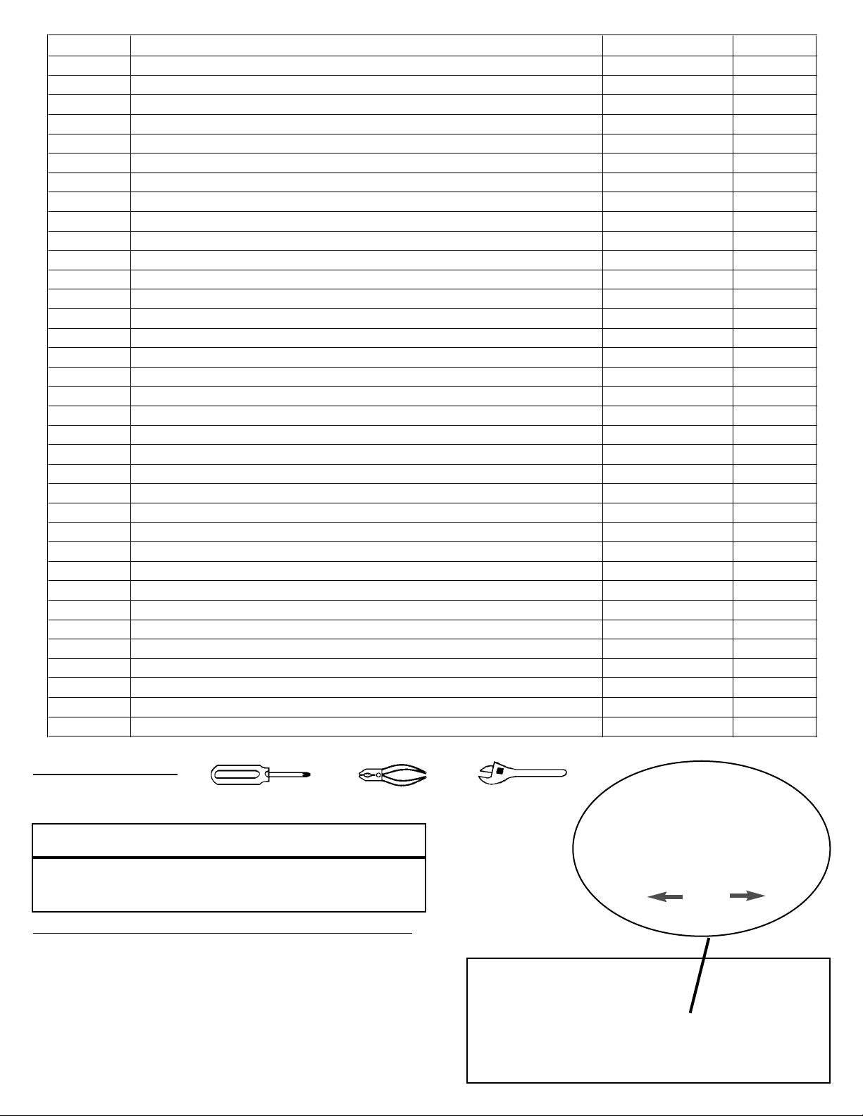
TOOLS REQUIRED:
To reduce the risk of a cut injury:
· Wear protective gloves when handling parts that have
sharp edges.
Phillips Screwdriver Pliers
Wrench
or
STEP 1) Cylinder Clamp/Back Panel Assembly:
Lay Back Panel (2/3) on floor. (FIG. 1A) Attach
LP Cylinder Clamp (4) to Back Panel by
squeezing clamp together to fit into the two
slotted openings; then release. (FIG. 1B) Make
sure the large loop is down against the panel.
(4) LP CYLINDER
CLAMP
(2/3) BACK PANEL
FIG. 1B
FIG. 1A
6
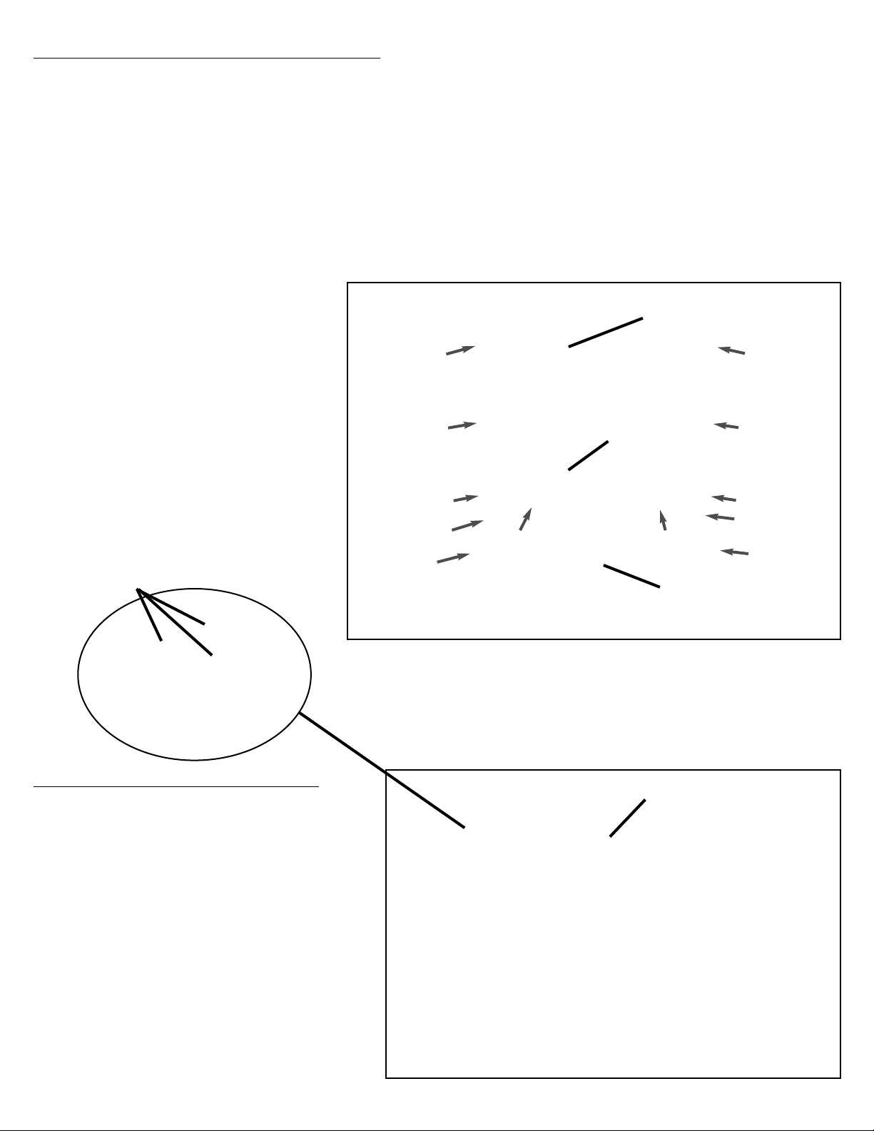
FIG. 2
STEP 3) Front Crossbar Assembly:
Turn cart assembly right side up. Attach
Front Crossbar (21/22) to side panels
with two M6 x 15 screws into the
threaded inserts in the ends of Side
Panels. (FIG. 3A)
Attach Bottom Panel Brace (9/10) to
Crossbar (21/22) with two Screws and
Nuts.
On top inside of Crossbar, attach three
M6 x 15 Screws through Side Panels into
the threaded inserts. (FIG. 3B)
(5/6) BOTTOM PANEL
INSTALL M6 (7) BOLTS
AND NUTS (8) AT ARROWS
(19/20) RIGHT
SIDE PANEL
(14/15) LEFT
SIDE PANEL
(21/22) CROSSBAR
ATTACH OUTER
SCREWS INTO
THREADED INSERTS
ATTACH WITH TWO SCREWS
AND NUTS TO BOTTOM
PANEL BRACE
FIG. 3A
ATTACH SCREWS TO
THREADED INSERTS
(TOP INSIDE)
FIG. 3B
ATTACH BOTTOM PANEL BRACE (9/10) TO BACK
PANEL BRACE (11/12) WITH ONE ST4.0 X 10MM SCREW (13)
(11/12) BACK
PANEL BRACE
(8) M6 NUT
(7) M6 x 15 BOLT
(13) ST4.0 x 10mm
Install four ST4.0 x10mm Screws (13)
from inside the Back Panel to the
LEFT Side Panel (14/15) and RIGHT
Side Panel (19/20).
STEP 2) Cart Sides and Bottom Assembly:
Lay Back Panel (2/3) on floor. (FIG. 2) Place Bottom Panel (5/6) against Back Panel edge and align
the holes. (FIG. 2) Install two M6x15 Bolts (7) through the holes and secure with two M6 Nuts (8).
Attach Bottom Panel Brace (9/10) to Bottom Panel (5/6) with two M6x15 Bolts and M6 Nuts. Attach
Back Panel Brace (11/12) to Back Panel (2/3) with two M6x15 Bolts and M6 Nuts. Secure Bottom
Panel Brace and and Back Panel Brace with one ST4.0 x10mm Screw (13).
Attach Left Side Panel (14/15) and Right Side Panel (19/20) to Bottom Panel with six M6x15 Screws
and M6 Nuts.
(2/3) BACK PANEL
7
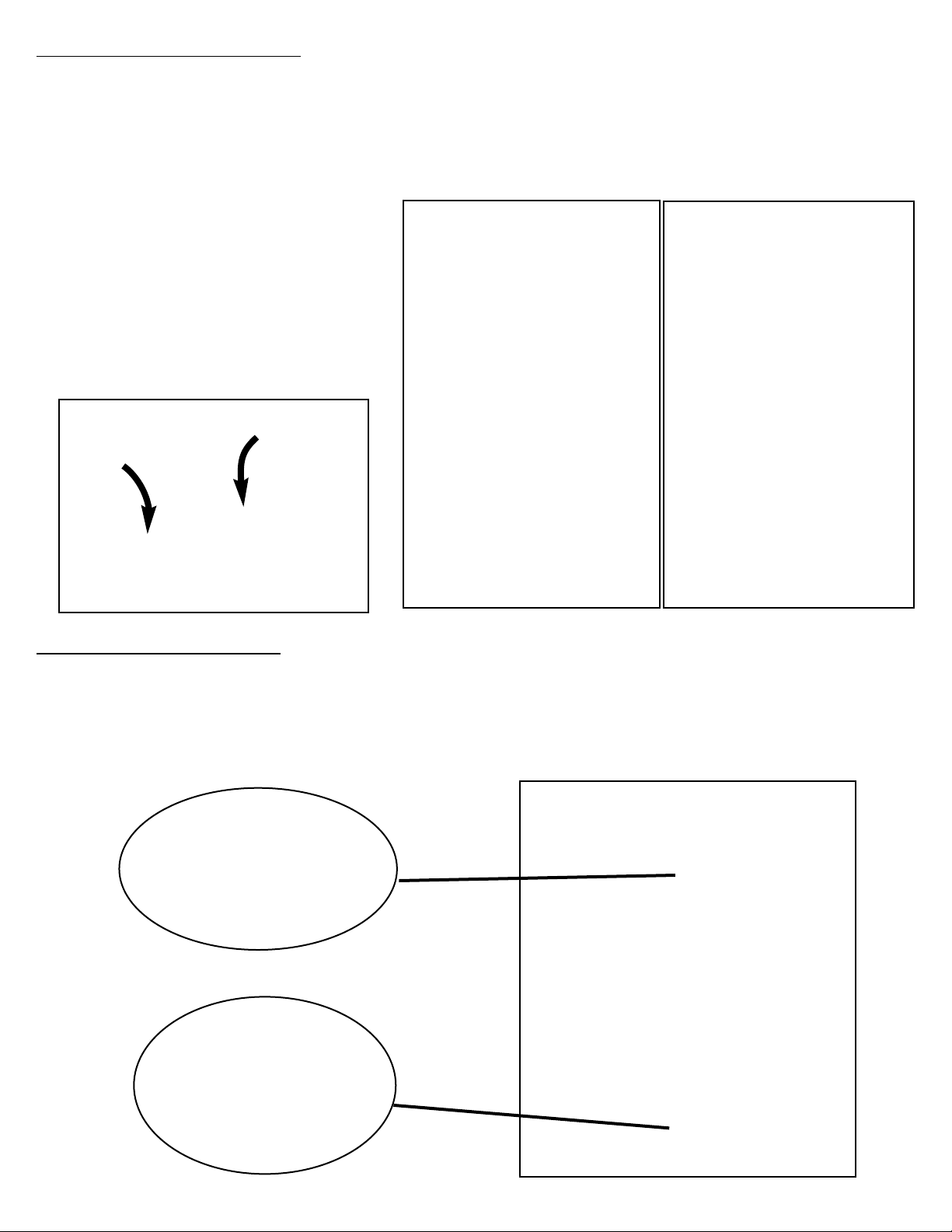
STEP
4) CASTER ASSEMBLY:
Lay cart on the floor with Back Panel side down. Assemble Fixed Casters (23) to the LEFT Side of
Bottom Panel and Swivel Lock Casters (24) to the RIGHT Side of Bottom Panel. Insert eight M6x15
Bolts (7) through the caster bracket holes into the threaded holes in the Bottom Panel. (FIG. 4A &
4B) Tighten the screws. Push the lever on the Swivel Lock Caster to lock so the caster wheel does
not roll. (FIG. 4C) Set cart assembly up on the the floor.
(24) LOCKING CASTER
(23) FIXED CASTER
FIG. 4A
FIG. 4B
STEP
5) DOOR ASSEMBLY:
Install LEFT Door (26/27) and RIGHT Door (28/29). (FIG. 5A) Note: Hinge Pins are spring-loaded.
Drop bottom door pin into Bottom Panel hole. (FIG. 5B) Swing top of door toward hole in top
Panel. Depress spring pin with thumb while sliding pin into Top Panel hole until it snaps into
place. (FIG. 5C)
(26/27) LEFT DOOR SHOWN,
RIGHT DOOR SAME.
FIG. 5A
FIG. 5C
FIG. 5B
FIG. 4C
(7) M6 x 15 BOLT
PUSH LEVER
DOWN THIS
SIDE TO LOCK
PUSH LEVER
DOWN THIS
SIDE TO
UNLOCK
STEP 6) HOOD/BOWL TO CART ASSEMBLY:
Lift the Hood/Bowl Assembly (30) over the cart assembly and set it down until it rests on the
inside top flanges of the cart. (FIG. 6A)
Align the holes in the side of the Hood/Bowl with the holes in the cart brackets. Insert
eight M6x15 (7) Bolts through the holes and tighten after all are installed. (FIG. 6B)
Align the flat keyed hole in the Control Knob (47) with the keyed stem of the four Control valves.
(FIG. 6A) Push the Control Knobs onto the four Valve stems.
8
To reduce the risk of injury from lifting: The following assembly will require 2-people.
FIG. 6A
INSIDE FLANGE ON
TOP OF CART
(7) M6 x 15 BOLT
HOOD/BOWL ASSEMBLED TO CART
REAR SIDE VIEW
FIG. 6B
(7) M6 x 15 BOLT
(47) CONTROL KNOB
(30) HOOD/BOWL
ASSEMBLY
 Loading...