

Aussie 6804, 6805 User Manual
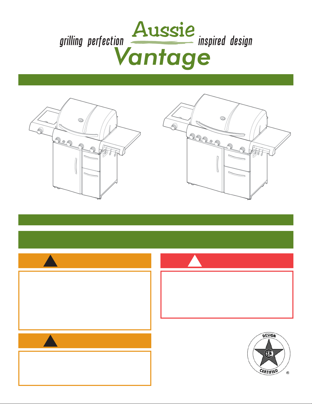
LP Gas Grill Assembly and Use Manual
6804 6805
For Outdoor Household Use Only. Not for Commercial Use.
Need Help? Need to Register Your Grill? Looking for Aussie Parts & Accessories?
Visit us online at www.AussieGrills.com Or call Aussie Customer Service at 1-800-251-7558
WARNING DANGER
! !
• Failure to follow these intructions could result in
fire or explosion which could cause death, serious
personal injury, or property damage.
• Read and follow instructions carefully before assembly or use.
• Do not use this product for any other purpose than
which it is intended.
• These instructions must be kept with the user.
SAVE THESE INSTRUCTIONS.
WARNING
!
• Do not store or use gasoline or other flammable
vapors and liquids in the vicinity of this or any
other appliance.
• An LP cylinder not connected for use shall not be
stored in the vicinity of this or any other appliance.
If you smell gas:
1. Shut off gas to the appliance.
2. Extinquish any open flame.
3. Open lid.
4. If odor continues, keep away from the appliance and immediately call your gas supplier or
your fire department.
2
NOTICE
Meco Corporation strives to be a quality supplier of consumer products. If we omitted
any parts needed for assembly, or you need troubleshooting information, please
contact us using our toll free number or visit our website.
It is important to register your grill and retain your receipt.
1-800-251-7558
8 am - 5 pm E.S.T. Monday - Friday
1-423-639-1171 (Telephone)
1-423-639-2570 (Fax)
CARBON MONOXIDE HAZARD
This appliance can produce carbon monoxide which
has no odor. Using it in an enclosed space can kill
you. Never use this appliance in an enclosed space,
such as a camper, tent, car, or home.
Consumer Service Department
MECO CORPORATION
1500 Industrial R o a d
Greenville, TN 37745 USA
www.aussiegrills.com
DANGER
!
WARNING
!
To reduce the risk of serious bodily injury or death from fire or explosion:
• Never use alcohol, prescription or non-prescription drugs while assembling or safely operating this appliance.
• Do not connect LP Gas Cylinder until assembly is complete.
CAUTION
!
To reduce the risk of a laceration hazard, wear protective gloves when handling parts that have sharp edges.
Tools Required for Assembly (Supplied with Grill):
Phillips Screwdriver (6804 & 6805) Wrench (6805)

Contents
3
Preparation for Assembly ..............................................3
Packing Lists
Model 6804 .................................................................4
Model 6805 .................................................................5
Assembly Instructions
Step 1 Caster Assembly ............................................ 6
Step 2 Cabinet Bottom Assembly .............................. 6
Step 3 Side Panel Assembly ......................................7
Step 4 Front Crossbar Assembly ...............................8
Step 5 Cabinet Upright Assembly .............................8
Step 6A Cylinder Guard Assembly .............................. 9
Step 6B Cylinder Blocking Wire Assembly ...................9
Step 7 Door Handle Assembly ..................................9
Step 8 Drawer Track Assembly ................................10
Step 9A Drawer Assembly .........................................10
Step 9B Drawer Positioning .......................................10
Step 10 Door Assembly ............................................ 11
Step 11 Hood/Body To Cart Assembly ...................... 11
Step 12 Side Table Assembly .................................... 12
Step 13 Side Burner Valve Assembly .........................13
Step 14 Side Burner Valve Connection- Model 6805 13
Step 15 Side Burner Igniter Wire Connection ............ 14
Step 16A Side Burner Control Knob Assembly ............ 14
Step 16B Side Burner Grid Assembly ..........................14
Step 17A Bottom Body Panel Assembly ....................... 15
Step 17B Foil Pan/Grease Pan Assembly ..................... 15
Step 18 Warming Rack Assembly .............................. 15
Step 19 Flame Diffuser/Cooking Grid Assembly .......16
Step 20 Battery in Igniter Installation ........................ 16
Connecting/Disconnecting the Gas
Using Gas .................................................................. 17
LP Gas Cylinder .......................................................... 17
LP Hose & Regulator ................................................... 18
Connecting LP Gas Cylinder ................................... 18
Disconnecting LP Gas Cylinder ............................... 18
Before Using Your Grill
Installation Codes ....................................................... 19
Selecting a Location ................................................... 19
How to Perform a Leak Test ........................................ 19
Lighting Grill Using the Pulse-Spark Ignitor ................ 20
Manually Lighting the Grill .........................................24
Lighting the Side Burner .............................................25
Check the Flame ........................................................ 25
Manually Lighting the Side Burner ..............................26
Lighting Sear and Rotisserie Burners on Model 6805. . 26
Cooking on the Gas Grill
Grill Cooking (Direct Method) ..................................... 27
Roasting (Indirect Method) ..........................................28
Warming Rack ............................................................ 29
End of Cooking Session ..............................................29
Care and Maintenance
Cleaning the Grill ....................................................... 30
How to Clean the Burners .......................................... 31
Storage ....................................................................33
Emergencies ............................................................ 34
Troubleshooting.......................................................34
Important Notice- LP Cylinder with OPD ...............36
Parts Illustrations
Model 6804 ...............................................................37
Parts List ...........................................................................38
Model 6805 ...............................................................39
Limited Warranty.......................................................40
Register your grill and retain your receipt.
Preparation for Assembly
Remove Grill and all the packaging from carton and place on floor. Make sure there are no loose parts.
NOTE: Before using your grill, read the instructions and your manual.
For easier set-up and assembly, follow instructions of each step in the order they are written as you look at the diagrams. If accessories mentioned in certain assembly steps do not come with your model, skip that step and proceed to
the next step that applies to your model.
If you have any questions or need help, contact Customer Service at 1-800-251-7558 or go to www.aussiegrills.
com. Be sure to have the grill model number and serial number printed on the black label, located inside the left door of
the cabinet. If you need replacement parts, look in the Parts List Section to find the exact parts you need. If you need
a replacement part under warranty, a proof of purchase will be necessary. You will be asked to forward your
proof of purchase via e-mail or to fax your proof of purchase to 423-639-1055 and reference your model and serial
number. It is important to register your grill and retain your receipt.
4
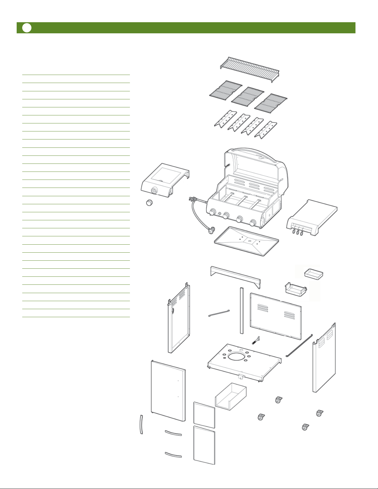
Packing List- Model 6804
Box Description
1 Cabinet Bottom Panel
Bottom Panel
2 Cabinet Side Panel- Right
Cabinet Side Panel- Left
Warming Rack
3 Left Side Shelf with Side Burner
Right Side Shelf
Door/Drawer handle, 2 pcs.
Large Door handle
Locking Caster, 2 pcs.
Fixed Casters, 2 pcs.
Side Burner Cooking Grid
Flame Diffuser, 4 pcs.
Hardware Package
Cylinder Wire guard
Cylinder Retainer Bolt
Side Burner Control Knob
Grease Pan
Foil Pan
Cylinder Blocking Wire
4 Cabinet Door- Left
Cabinet Door- Right
Drawer Front
5 Cabinet Back Panel
Front Crossbar
Cabinet Upright
Back Panel Brace
Drawer Tracks, 2 pcs.
6 Cooking Grid, 3 pcs.
7 Drawer Body
8 Hood/Body
2
6
3
3
8
3
3
1
5
3
3
5
3
2
3
5
Detailed Parts List and Illustrations
may be found on pages 37 & 38.
3
3
1
4
3
7
3
4
4
3
2
3
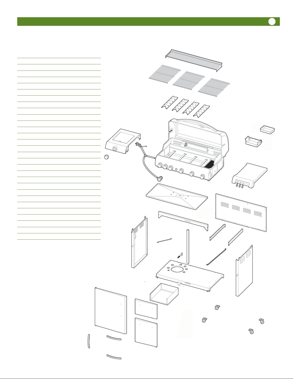
Box Description
1 Cabinet Bottom Panel
Bottom Panel
2 Cabinet Side Panel- Right
Cabinet Side Panel- Left
Warming Rack
3 Left Side Shefl with Side Burner
Right Side Shelf
Door/Drawer handle, 3 pcs.
Locking Caster, 2 pcs.
Fixed Casters, 2 pcs.
Side Burner Cooking Grid
Flame Diffuser, 4 pcs.
Hardware Package
Cylinder Wire guard
Cylinder Retainer Bolt
Side Burner Control Knob
Grease Pan
Foil Pan
Cylinder Blocking Wire
4 Cabinet Door- Left
Cabinet Door- Right
Drawer Front
5 Cabinet Back Panel
Front Crossbar
Cabinet Upright
Back Panel Brace
Drawer Tracks, 2 pcs.
6 Cooking Grid, 3 pcs.
7 Drawer Body
8 Hood/Body
Detailed Parts List and Illustrations
may be found on pages 38 & 39
5
Packing List- Model 6805
2
6
3
3
3
3
3
3
8
1
3
5
2
3
3
5
5
5
3
3
5
1
4
7
3
4
3
3
3
3
3
2
3
3
6
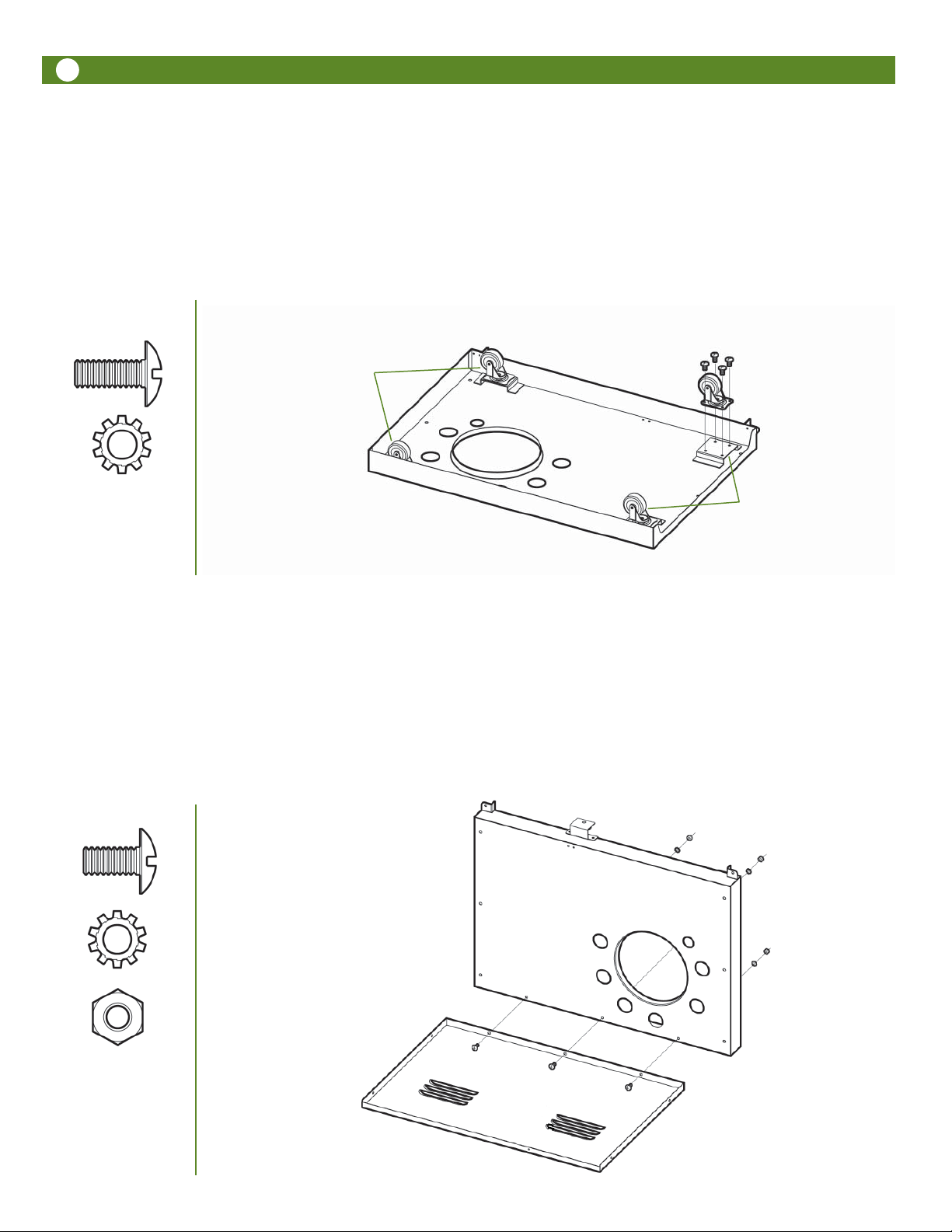
Assembly Instructions
Step 1
Caster Assembly
Lay Cabinet Bottom Panel upside down, so that the flat surface is on the floor. Assemble Fixed Casters to the LEFT Side
(the side closest to the cutouts) of Cabinet Bottom Panel and Swivel Lock Casters to the RIGHT Side of Cabinet Bottom
Panel. Insert 1/4-20 x .60” Bolts through the caster bracket holes into the threaded holes in the Cabinet Bottom Panel.
Tighten the bolts. Push the lever on the two Locking Casters to lock so the caster wheels do not roll.
Fixed Casters
1/4-20 x .60” Bolt set
16 p c
Swivel Lock Casters
Step 2
Cabinet Bottom Assembly
With Back Panel on floor, place Cabinet Bottom Panel against Back Panel edge and align the holes. Install three
1/4-20 x .50 Bolts through the holes and secure with three 1/4-20 Nuts.
1/4-20 x .50” Bolt set
Model 6804- 3 pcs
Model 6805- 4 pcs
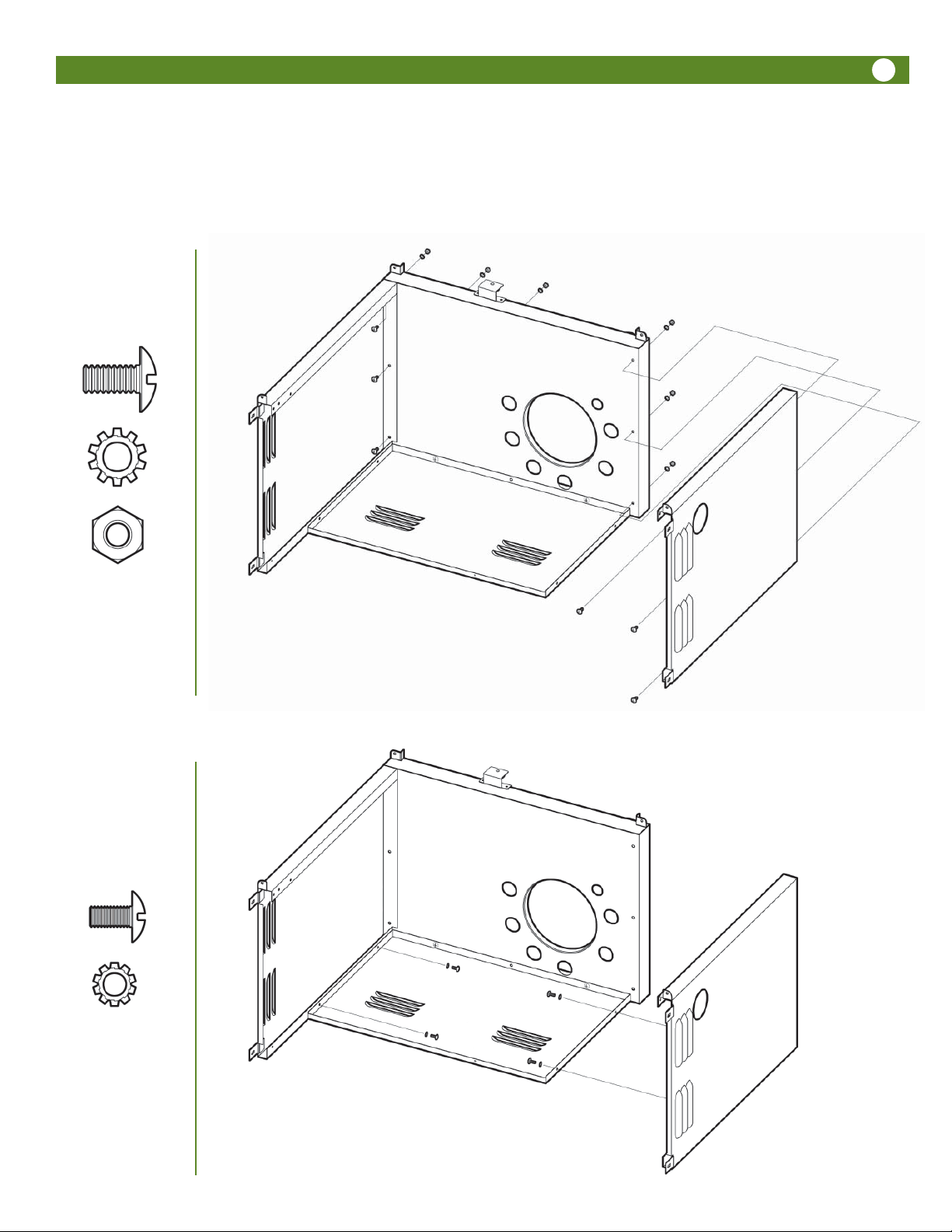
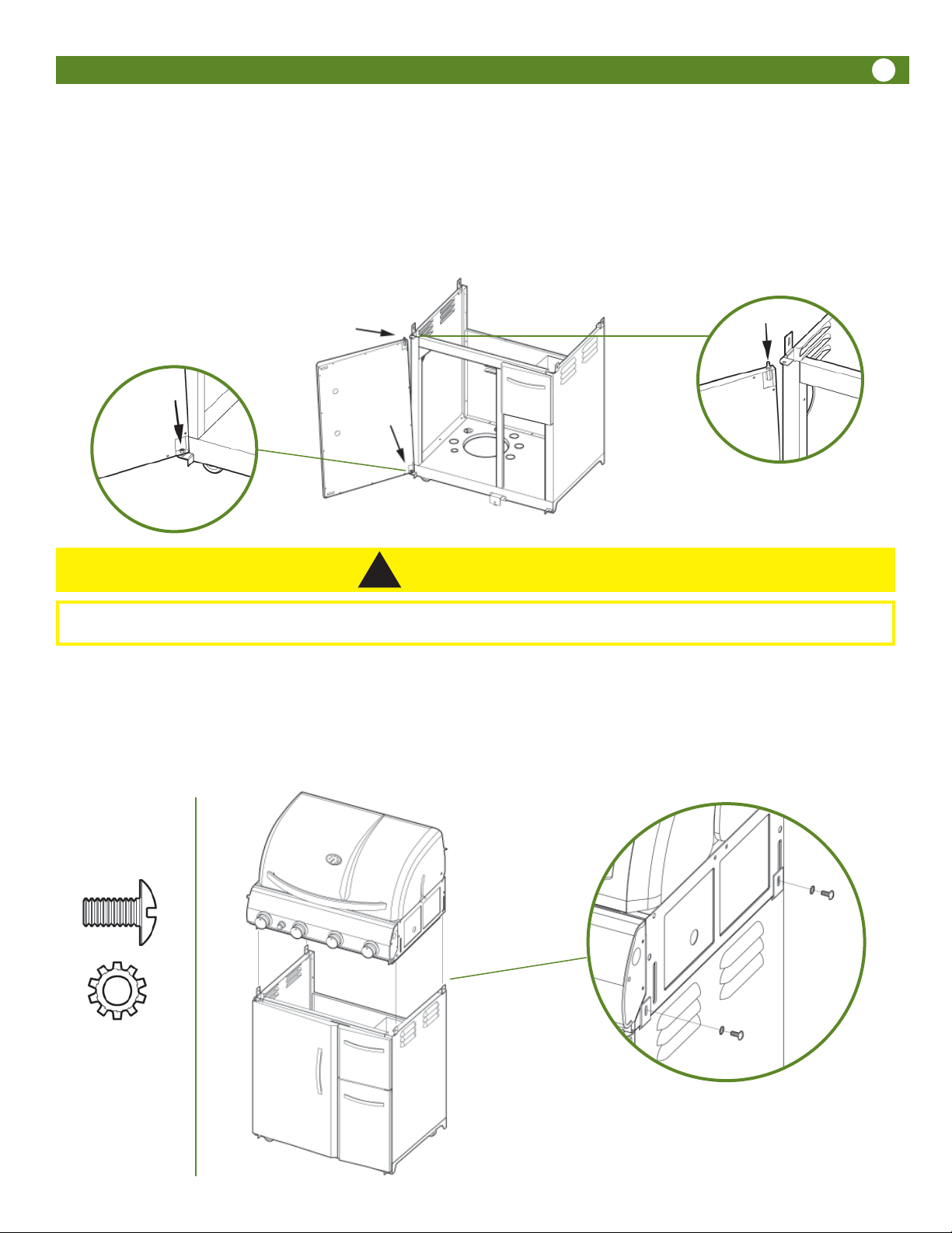
Step 3
Side Panel Assembly
Attach Left Side Panel and Right Side Panel to Cabinet Bottom Panel with six 1/4-20 x .50” Bolts and 1/4-20 Nuts.
77
1/4-20 x .50” Bolt set
6 pc
Secure Left and Right Side Panels to Back Panel with four 5/32 x .31” Bolts through the inside of the Back Panel.
5/32 x .31” Bolt set
4 pc

8
Step 4
Front Crossbar Assembly
Turn cart assembly up on casters. Attach Front Crossbar, with the triangle braces facing down and the flat surface to
the front, to Side Panels with six 1/4-20 x .50” Bolts into the threaded holes in the top inside ends of Side Panels.
front crossbar
1/4-20 x .50” Bolt set
6 pc
Step 5
Cabinet Upright Assembly
Attach Cabinet Upright to Cabinet Bottom and Front Crossbar with four 5/32 x .31” Bolts. Orient Upright so that Matchholder/Chain is closest to top of cabinet (Front Crossbar).
5/32 x .31” Bolt set
4 pc
WARNING
!
To reduce the risk of serious bodily injury or death from fire or explosion:
• Never remove guards or devices to prevent storage of spare or oversize LP Gas Cylinders not recommended for
this grill.
Step 6
A. Cylinder Guard Assembly
Attach Wire Guard to Front Crossbar and Back Panel with two 5/32 x .47” Bolts.
B. Cylinder Blocking Wire Assembly
Attach Cylinder Blocking Wire to Right Side Panel with one 5/32 x .47” Bolt and nut. Attach to Bottom Panel with one
5/32 x .47” Bolt.
9
A
5/32 x .47” Bolt set
4 pc
5/32 Nut
1 pc
Step 6C
Center Wheel Assembly (Model 6804)
Remove screws from Cabinet Bottom Panel.
Locate “Center Wheel” as shown and fasten in place to
Cabinet Bottom Panel with screws that were just removed.
B
nut
Step 7
Door Handle Assembly
Assemble Handle to Left Door using two 5/32 x .22” Bolts.
Repeat with Right Door.
Note: 2 extra screws provided.
5/32 x .22” Bolt set
4 pc
10
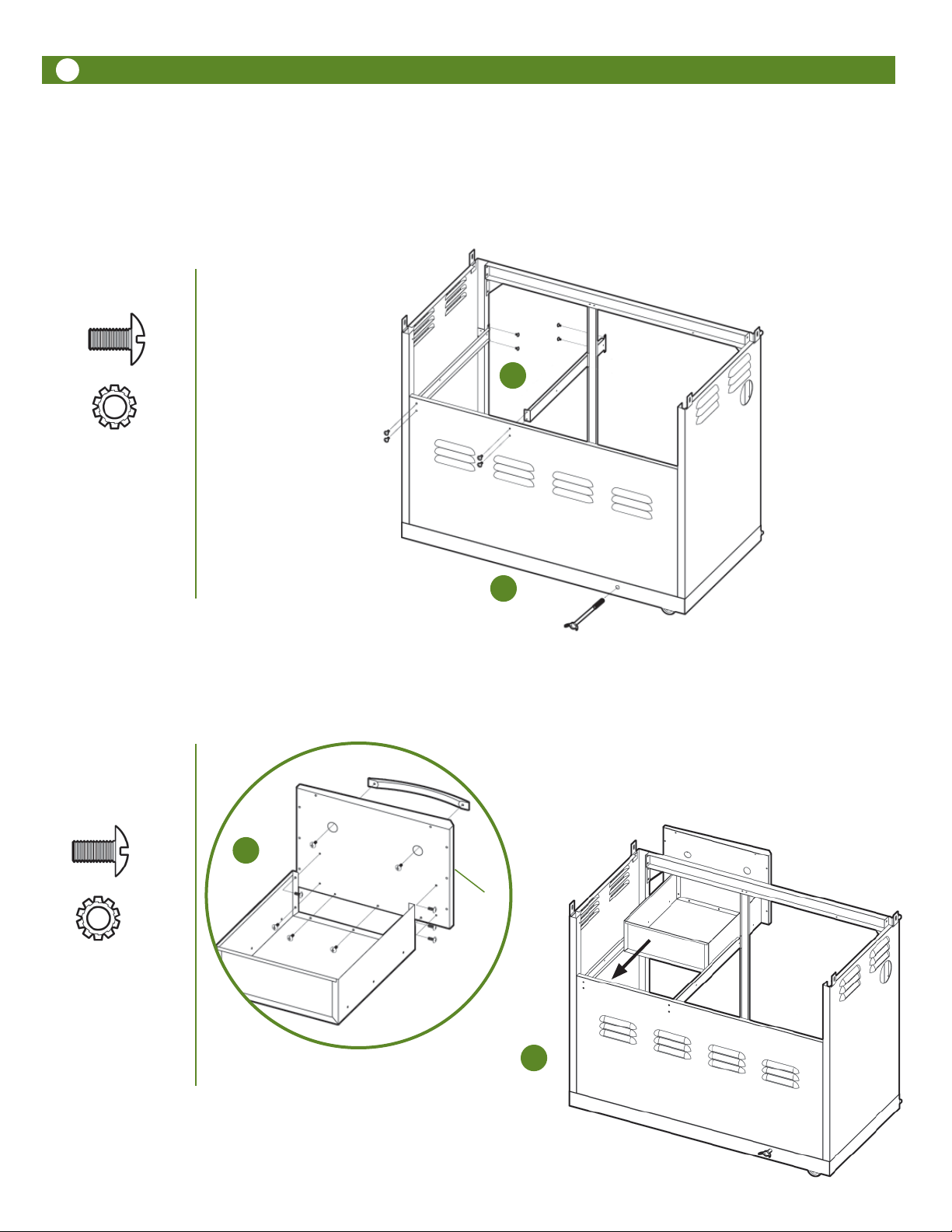
Step 8 Model 6805 & 6804 with drawer
Drawer Track Assembly (and Cylinder Retaining Bolt Installation for Model 6805)
Attach one Drawer Track to Back Panel and Cabinet Upright using four 5/32 x .31” Bolts. Attach other Drawer Track
A.
to Back Panel and Right Side Panel using four 5/32 x .31” Bolts.
B. Install the Cylinder Retainer Bolt through the hole in the back of the Bottom Shelf into the nut welded underneath.
A
5/32 x .31” Bolt set
8 pc
B
Step 9 Model 6805 & 6804 with drawer
A. Drawer Assembly
Assemble Handle to Drawer Front with two 5/32 x .22” Bolts. Note: 1 extra screw provided.
Attach Drawer Front to Drawer Body with 5/32 x .31” Bolts into threaded holes in inside of Drawer Front.
5/32 x .22” Bolt set
2 pc
Cylinder Retainer Bolt
A
drawer
front
5/32 x .31” Bolt set
Model 6804- 6 pcs
Model 6805- 7 pcs
B
B. Drawer Positioning
Slide Drawer Assembly over the Drawer Tracks to position the Drawer.
Step 10
Door Assembly
Install LEFT Door. Drop bottom door pin into Cabinet Bottom Panel hole. Swing top of door toward hole in top of Left
Side Panel. Depress spring-loaded pin with thumb while sliding pin into Left Side Panel hole until it snaps into place.
Right Door assembly is similar; Fixed pin is under drawer and inserts into hole in door and spring-loaded pin is in the
BOTTOM of small door and functions the same.
Depress
Left Door shown,
Right Door under
drawer.
11
CAUTION
!
To reduce the risk of bodily injury from lifting, the following assembly steps #s 11 and 12 will require two people.
Step 11
Hood/Body To Cart Assembly
Lift the Hood/Body Assembly over the cart assembly and set it down until it rests on the inside top flanges of the cart.
Align the holes in the side of the Hood/Body with the holes in the Side Panel brackets. Insert four 1/4-20 x .50 Bolts
through the holes in cabinet flanges and into threaded inserts in firebox and tighten after all are installed.
Right side
view
1/4-20 x .50” Bolt set
4 pc
NOTE:
Model 6805: Carefully route gas and electrical lines
when placing hood/body assembly on cart. Be sure no
lines are pinched between hood/body assembly and cart.
12
CAUTION
!
Prior to performing any further assembly, PERFORM “FIRST TIME USE” LEAK TEST
as detailed on pages 20-21.
If the grill is fully assembled before per forming the First Time Use leak test, the side tables will need to be removed in order to perform the
leak test on the valves behind the knobs, inside the control panel.
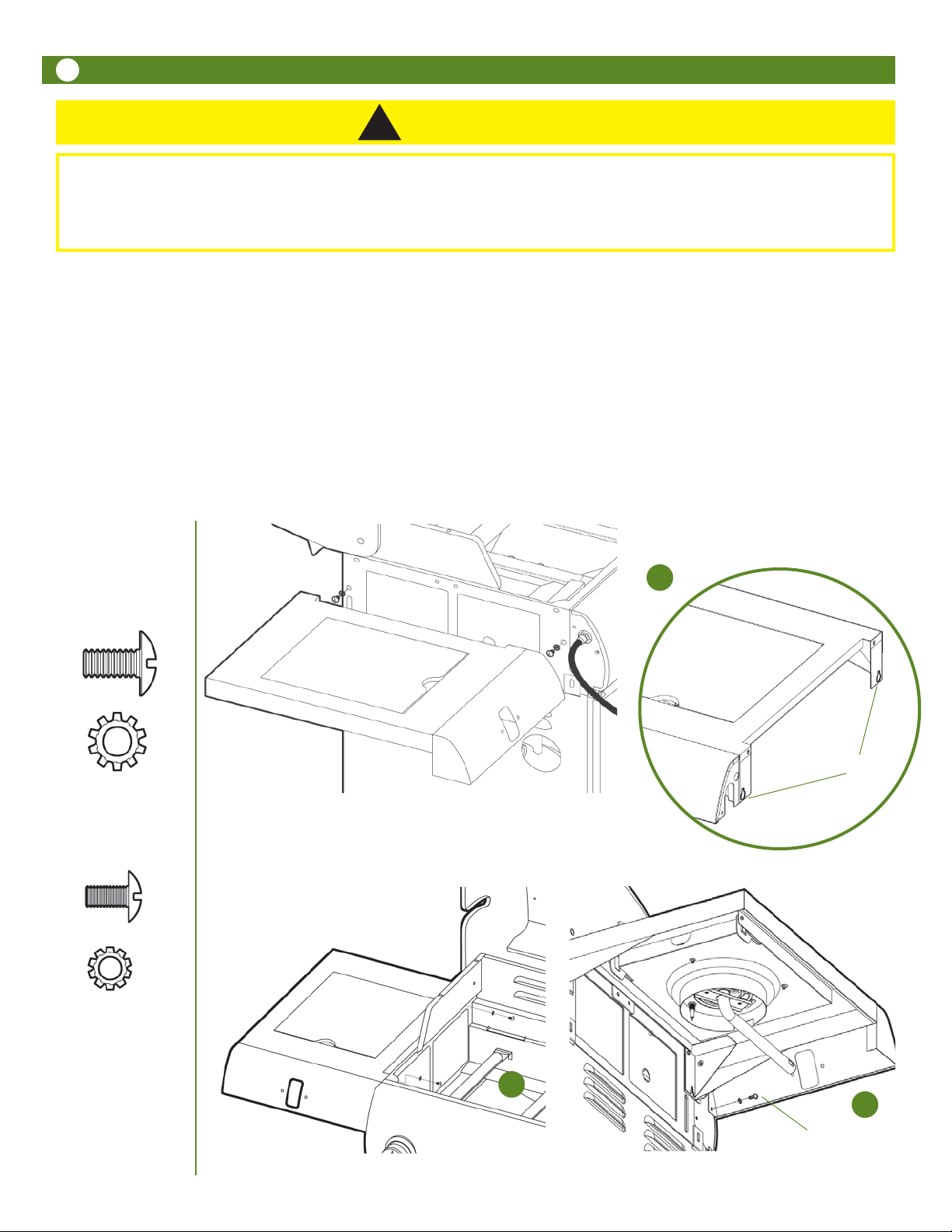
Step 12
Side Table Assembly
Screw two 1/4-20 x .50” Bolts into the two bottom threaded inserts on the outside of the Bowl. Do not screw Bolts
A.
all the way. Leave 1/8” of each Bolt exposed.
Align the bottom two holes (“keyhole slots” in detail) on the inner side of the LEFT Side Table with the two bolts threaded partly into the inserts in the Side of the Bowl then slide the Side Burner Table over the Bolts.
B. Holding the Side Burner Table in place, install two 1/4-20 x .50” Bolts from the inside of the Bowl into the two top
threaded holes in the Side Table.
C. From under the Side Table, install one 5/32 x .31” bolt through the Side Table end into the side of the Bowl.
Repeat this assembly for the RIGHT Side Table. Tighten all bolts.
1/4-20 x .50” Bolt set
8 pc
5/32 x .31” Bolt set
2 pc
A
Keyhole Slots
B
C
5/32 x .31” Bolt
 Loading...