

Aussie 6122S8X641, 6112S8X641 User Manual
LP Gas Grill Assembly and Use Manual
6122S8X641
For Outdoor Household Use Only. Not for Commercial Use.
Need Help? Need to Register Your Grill? Looking for Aussie Parts & Accessories?
Visit us online at www.AussieGrills.com Or call Aussie Customer Service at 1-800-251-7558
WARNING
!
• Failure to follow these intructions could result in
fire or explosion which could cause death, serious
personal injury, or property damage.
• Read and follow instructions carefully before assembly or use.
• Do not use this product for any other purpose than
which it is intended.
• These instructions must be kept with the user.
SAVE THESE INSTRUCTIONS.
WARNING
!
If you smell gas:
6112S8X641
DANGER
!
1. Shut off gas to the appliance.
2. Extinquish any open flame.
3. Open lid.
4. If odor continues, keep away from the appliance and immediately call your gas supplier or
your fire department.
• Do not store or use gasoline or other flammable
vapors and liquids in the vicinity of this or any
other appliance.
• An LP cylinder not connected for use shall not be
stored in the vicinity of this or any other appliance.

2
NOTICE
Meco Corporation strives to be a quality supplier of consumer products. If we omitted
any parts needed for assembly, or you need troubleshooting information, please
contact us using our toll free number or visit our website.
It is important to register your grill and retain your receipt.
1-800-251-7558
8 am - 5 pm E.S.T. Monday - Friday
1-423-639-1171 (Telephone)
1-423-639-2570 (Fax)
CARBON MONOXIDE HAZARD
This appliance can produce carbon monoxide which
has no odor. Using it in an enclosed space can kill
you. Never use this appliance in an enclosed space,
such as a camper, tent, car, or home.
Consumer Service Department
MECO CORPORATION
1500 Industrial R o a d
Greenville, TN 37745 USA
www.aussiegrills.com
DANGER
!
WARNING
!
To reduce the risk of serious bodily injury or death from fire or explosion:
• Never use alcohol, prescription or non-prescription drugs while assembling or safely operating this appliance.
• Do not connect LP Gas Cylinder until assembly is complete.
CAUTION
!
To reduce the risk of a laceration hazard, wear protective gloves when handling parts that have sharp edges.
Tools Required for Assembly:
Phillips Screwdriver
Pliers OR Wrench

Contents
3
Preparation for Assembly ..............................................3
Parts Identification
Parts Illustration Model 6122S8X641 ............................4
Parts List Model 6122S8X641 .......................................5
Parts Illustration Model 6112S8X641 ............................ 6
Parts List Model 6112S8X641 ........................................7
Assembly Instructions
Step 1 Front Leg Frame Assembly ............................. 8
Step 2 Rear Leg Frame Assembly ..............................8
Step 3 Rear Crossbrace Assembly ............................. 9
Step 4 Supports and Crossbrace Assembly. .............. 9
Step 5 Cart Frame Assembly................................... 10
Step 6 Side Table Support Assembly .......................10
Step 7 Heat Shield Assembly .................................. 11
Step 8 Manifold and Piezo Igniter Assembly ........... 11
Step 9 Control Panel to Cart Frame Assembly......... 12
Step 10 Shroud Assembly ......................................... 12
Step 11 Shroud to Cart Assembly .............................13
Step 12 Wheel Assembly ..........................................13
Step 13 Side Tables to Cart Assembly ....................... 14
Step 13A Side Burner Valve Ass’y (Model 6122) .......... 14
Step 14 Bowl to Cart Assembly ................................. 15
Step 15 Drip Cup Wire Assembly .............................. 15
Step 16 Main Burner Assembly ................................. 16
Step 17 Side Burner Electrode Ass’y (Model 6122) .... 17
Step 18 Side Burner Assembly (Model 6122) ............. 17
Step 19 Main Burner Electrode Assembly.................. 18
Step 20 Hood Handle Assembly ............................... 19
Step 21 Hood / Hinge Assembly ............................... 19
Step 22A Flavor Activator Assembly ............................20
Step 22B Warming Rack Assembly .............................. 20
Step 23A Cooking Grid Assembly ............................... 20
Step 23B Control Knob Assembly ............................... 20
Step 24 Cylinder Blocking Wire Assembly ................. 21
Step 25A Drip Cup Assembly ......................................21
Step 25B Cylinder Retainer Wire Assembly .................21
Connecting/Disconnecting the Gas
Using Gas .................................................................. 22
LP Gas Cylinder .......................................................... 22
LP Hose & Regulator ................................................... 23
Connecting LP Gas Cylinder .......................................23
Disconnecting LP Gas Cylinder ................................... 23
Before Using Your Grill
Installation Codes .......................................................24
Selecting a Location ................................................... 24
Performing a Leak Test ............................................... 24
How to Perform a Leak Test ........................................ 25
Lighting Grill Using the Pulse-Spark Ignitor ................ 26
Check the Flame ........................................................ 26
Manually Lighting the Grill .........................................28
Lighting the Side Burner .............................................29
Manually Lighting the Side Burner ..............................29
Cooking on the Gas Grill
Grill Cooking (Direct Method) .....................................30
Roasting (Indirect Method) .......................................... 31
Warming Rack ............................................................32
End of Cooking Session ..............................................32
Care and Maintenance
Cleaning the Grill ....................................................... 33
How to Clean the Burners ..........................................34
Storage ....................................................................36
Emergencies ............................................................ 37
Troubleshooting....................................................... 37
Important Notice- LP Cylinder with OPD ...............39
Limited Warranty.......................................................40
Register your grill and retain your receipt.
Preparation for Assembly
Remove Grill and all the packaging from carton and place on floor. Make sure there are no loose parts.
NOTE: Before using your grill, read the instructions and your manual.
For easier set-up and assembly, follow instructions of each step in the order they are written as you look at the diagrams. If accessories mentioned in certain assembly steps do not come with your model, skip that step and proceed to
the next step that applies to your model.
If you have any questions or need help, contact Customer Service at 1-800-251-7558 or go to www.aussiegrills.
com. Be sure to have the grill model number and serial number printed on the black label, located on the back of the cart
shroud. If you need replacement parts, look in the Parts List Section to find the exact parts you need. If you need a re-
placement part under warranty, a proof of purchase will be necessary. You will be asked to forward your proof
of purchase via e-mail or to fax your proof of purchase to 423-639-1055 and reference your model and serial number.
It is important to register your grill and retain your receipt.
4
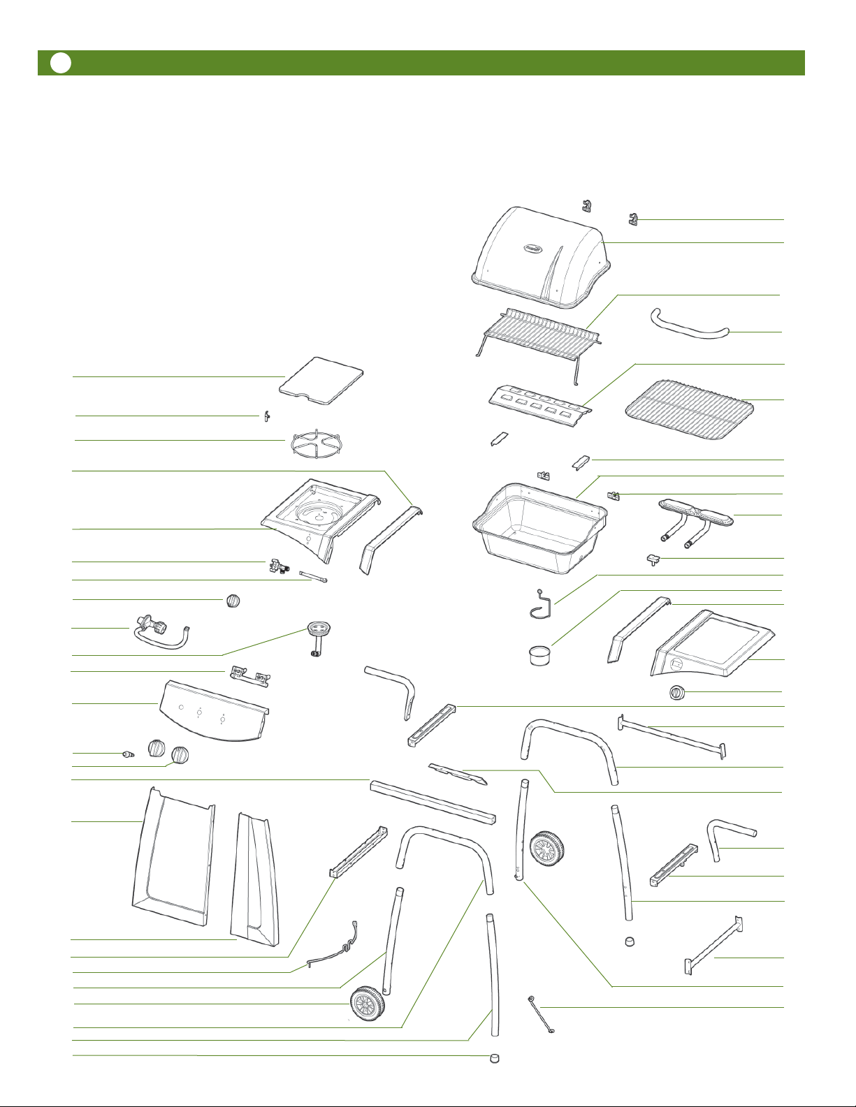
Parts Illustration - Model 6122S8X641
If you need replacement parts, refer to the Parts
Illustrations to find the exact parts you need. If you
have any questions or need help, contact Cus-
tomer Service at 1-800-251-7558 or go to www.
aussiegrills.com. Be sure to have the grill model
number and serial number printed on the black label,
located on the back of the cart shroud. If you need
a replacement part under warranty, a proof of
purchase will be necessary. You will be asked to
forward your proof of purchase via e-mail or to fax
your proof of purchase to 423-639-1055 and reference your model and serial number. It is important
to register your grill and retain your receipt.
24
25
26
27
6A
10
11
12
13
14
1
2
3
4
5
6
7
8
9
28
29
30
31
32
33
34
35
36
37
38
39
40
41
42
43
15
16
17
18
19
20
21
22
23
44
45
46
47
48
49

Parts List- Model 6122S8X641
5
Key Description Quantity
1 Side Burner Cover 1
2 Side Burner Electrode 1
3 Side Burner Cooking Grid 1
4 Left Side Table Accent 1
5 Left Side Table 1
6 Side Burner Valve 1
6A Valve to Manifold Hose 1
7 Side Burner Control Knob 1
8 Regulator Assembly 1
9 Side Burner 1
10 Manifold Assembly 1
11 Control Panel 1
12 Piezo Igniter Button 1
13 Main Burner Control Knob 2
14 Front Side Table Support 1
15 Left Shroud H alf 1
16 Right Shroud Half 1
17 Cylinder Support 1
18 Cylinder Retainer Wire 1
19 Left Front Leg 1
20 Wheel 2
21 Front U-Leg 1
22 Right Front Leg 1
23 Foot Cap 2
24 Hood Hinge Half 2
25 Hood 1
26 Warming Rack 1
27 Hood Handle 1
28 Flavor Activator 1
29 Main Cooking Grid 1
30 Flavor Activator Support 2
31 Bowl 1
32 Bowl Hinge Half 2
33 Main Burner 1
34 Main Electrode Assembly 1
35 Drip Cup Holder Wire 1
36 Drip Cup 1
37 Right Side Table Accent 1
38 Right Side Table 1
39 Timer 1
40 Left Bowl Support 1
41 R e ar C ros s b r a c e 1
42 Rear U-Leg 1
43 Heat Shield 1
44 Rear Side Table Support 2
45 Right Bowl Support 1
46 Right Rear Leg 1
47 Right Side Crossbrace 1
48 Left Rear Leg 1
49 Cylinder Blocking Wire 1
Hardware Pack (Part# 03.6911.13)
Description Quantity
1/4-20 x .39” Bolt 44
1/4-20 x .59” Bolt 4
1/4-20 x .79” Bolt 4
1/4-20 x 1.50” Bolt 6
1/4-20 Hex Nut 15
5/32-30 x .47” Bolt 2
5/32-30 x .39” Bolt 2
M4 x .31” Bolt 6
#5 x .31” Tapping Screw 3
5/32-30 Hex Nut 1
Fiber Washer 6
Thermal Baffle Washer 2
Hood Hinge Axle 2
Axle Pin 4
Wheel Axles 2
6
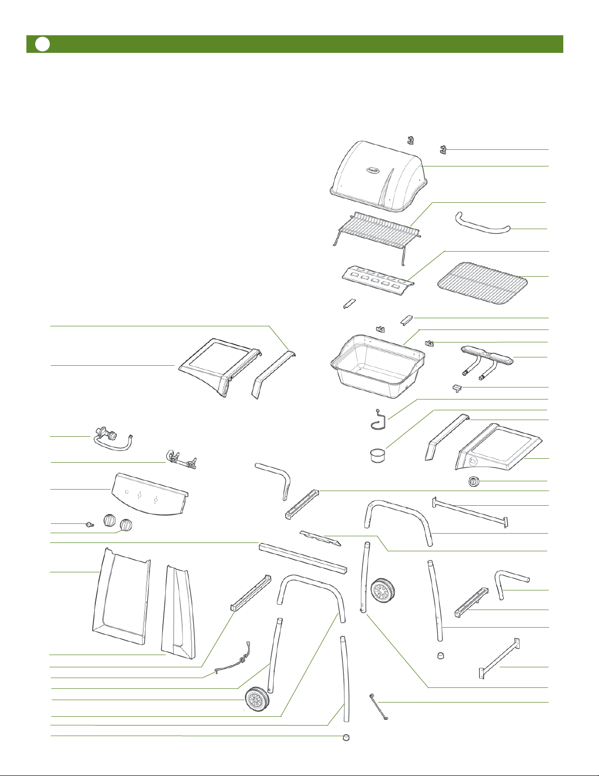
Parts Illustration - Model 6112S8X641
If you need replacement parts, refer to the Parts
Illustrations to find the exact parts you need. If you
have any questions or need help, contact Cus-
tomer Service at 1-800-251-7558 or go to www.
aussiegrills.com. Be sure to have the grill model
number and serial number printed on the black label,
located on the back of the cart shroud. If you need
a replacement part under warranty, a proof of
purchase will be necessary. You will be asked to
forward your proof of purchase via e-mail or to fax
your proof of purchase to 423-639-1055 and reference your model and serial number. It is important
to register your grill and retain your receipt.
24
25
26
27
28
29
10
11
12
13
14
15
4
5
8
30
31
32
33
34
35
36
37
38
39
40
41
42
43
44
16
17
18
19
20
21
22
23
45
46
47
48
49

Parts List- Model 6112S8X641
7
Key Description Quantity
4 Left Side Table Accent 1
5 Left Side Table 1
8 Regulator Assembly 1
10 Manifold Assembly 1
11 Control Panel 1
12 Piezo Igniter Button 1
13 Main Burner Control Knob 2
14 Front Side Table Support 1
15 Lef t Shroud Half 1
16 Right Shroud Half 1
17 Cylinder Support 1
18 Cylinder Retainer Wire 1
19 Left Front Leg 1
20 Wheel 2
21 Front U-Leg 1
22 Right Front Leg 1
23 Foot Cap 2
24 Hood Hinge Half 2
25 Hood 1
26 Warming Rack 1
27 Hood Handle 1
28 Flavor Activator 1
29 Main Cooking Grid 1
30 Flavor Activator Support 2
31 Bowl 1
32 Bowl Hinge Half 2
33 Main Burner 1
34 Main Electrode Assembly 1
35 Drip Cup Holder Wire 1
36 Drip Cup 1
37 Right Side Table Accent 1
38 Right Side Table 1
39 Timer 1
40 Left Bowl Support 1
41 Rear Cros sbrace 1
42 Rear U-Leg 1
43 Heat Shield 1
44 Rear Side Table Support 2
45 Right Bowl Support 1
46 Right Rear Leg 1
47 Right Side Crossbrace 1
48 Left Rear Leg 1
49 Cylinder Blocking Wire 1
Hardware Pack (Part# 03.6911.13)
Description Quantity
1/4-20 x .39” Bolt 44
1/4-20 x .59” Bolt 4
1/4-20 x .79” Bolt 4
1/4-20 x 1.50” Bolt 6
1/4-20 Hex Nut 15
5/32-30 x .47” Bolt 2
5/32-30 x .39” Bolt 2
M4 x .31” Bolt 6
#5 x .31” Tapping Screw 3
5/32-30 Hex Nut 1
Fiber Washer 6
Thermal Baffle Washer 2
Hood Hinge Axle 2
Axle Pin 4
Wheel Axles 2
8
Assembly Instructions
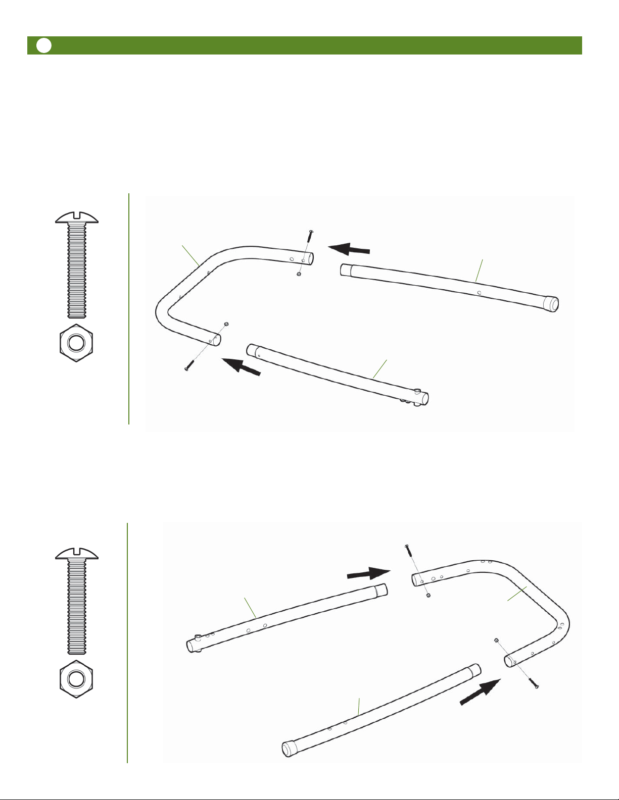
Step 1
Front Leg Frame Assembly
Identify parts and lay on floor as shown. Parts are named for their assembled position on the grill. Note in illustrations,
holes with threaded inserts are oriented facing up, as well as to the center. Insert Right and Left Front Legs into the
ends of the Front U-Leg. Fasten in place with 2) 1/4-20 x 1.50” bolts and 1/4-20 nuts. Do NOT tighten completely at
this stage.
Front U-Leg
Right Front Leg
Left Front Leg
1/4-20 x 1.50” Bolt
and Nut
2 pcs Each
Step 2
Rear Leg Frame Assembly
Identify parts and lay on floor as shown. Parts are named for their assembled position on the grill. Note in illustrations,
holes with threaded inserts are oriented facing up, as well as to the center. Insert Right and Left Rear Legs into the
ends of the Rear U-Leg. Fasten in place with 2) 1/4-20 x 1.50” bolts and 1/4-20 nuts. Do NOT tighten completely at
this stage.
Left Rear Leg
Rear U-Leg
1/4-20 x 1.50” Bolt
and Nut
2 pcs Each
Right Rear Leg
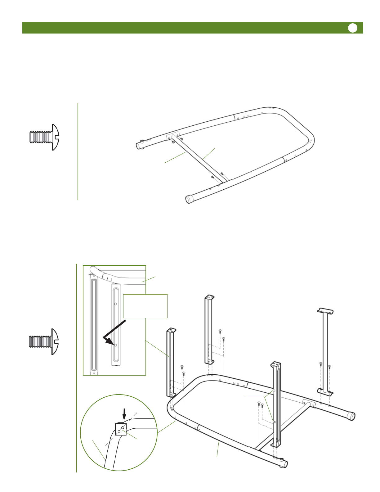
Step 3
Rear Crossbrace Assembly
Attach Rear Crossbrace inside Rear Leg Frame with 4) 1/4-20 x .39” Bolts. Note: The flanges on the ends of the crossbrace tube are angled inward toward the top to match the angle of the legs.
NOTE:
Threaded Insert on top
9
1/4-20 x .39” Bolt
4 pcs
Rear
Crossbrace
Step 4
Bowl Supports, Cylinder Support and Side Crossbrace Assembly
Attach the Left and Right Bowl Supports, Clyinder Support and Crossbrace to rear leg assembly with 8) 1/4-20 x .39”
Bolts. Note: Each part must be oriented as shown for proper assembly. Bolts should be snug but do NOT tighten completely at this stage. Note: The flanges on the ends of the crossbrace tube are angled inward toward the top to match
the angle of the legs.
Rear Leg Assembly
Left Bowl Support
Holes are closest to
OUTSIDE edge
Left
Bowl
Support
Right
Bowl Support
Side Crossbrace
Cylinder Support
1/4-20 x .39” Bolt
8 pcs
Low side of raised area
to center
Rear Leg
Assembly
NOTE:
notches closest
together to outside
Holes in Bowl
Support align
with leg
Rear Leg Assembly
10 7
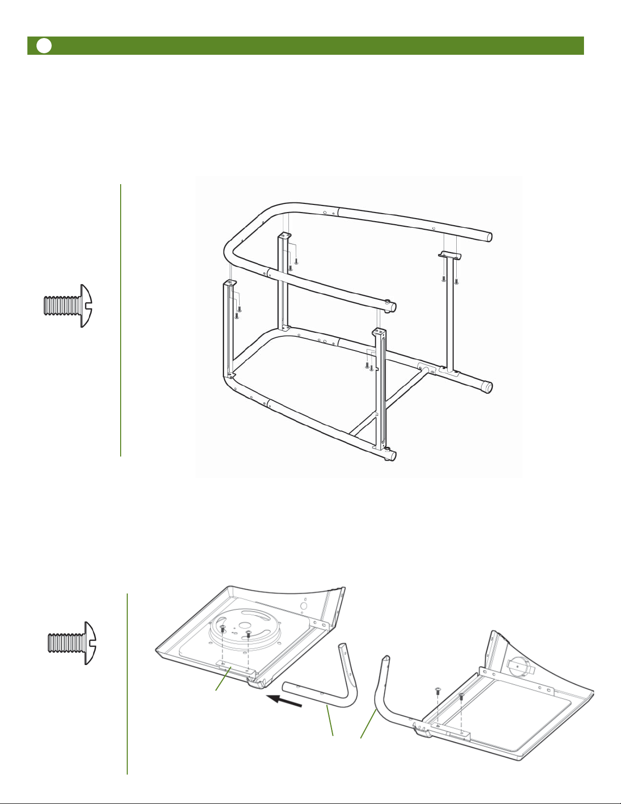
Step 5
Cart Frame Assembly
With Rear Leg Frame with Supports and Crossbrace laying on floor, place Front Leg Frame on top and align holes. Attach Front Leg Frame to Supports with 8) 1/4-20 x .39” Bolts. Tighten all securely.
Front Leg Frame
1/4-20 x .39” Bolt
8 pcs
Rear Leg Frame
with Supports
Step 6
Side Table Support Assembly
Lay Left and Right Side Tables upside down on floor. Insert round leg of Side Table Support into C-channel on
Side Table and align holes. Fasten in place with 2) 1/4-20 x .39” Bolts for each Support. (4 total for both Supports)
Note: Model 6122 Left Side Table is illustrated. Model 6112 Left Side Table has no side burner.
Left Side Table
Model (6122)
Right Side Table
1/4-20 x .39” Bolt
4 pcs
C-channel
Side Table Supports
11
CAUTION
!
To reduce the risk of a laceration hazard, wear protective gloves when handling parts that have sharp edges.
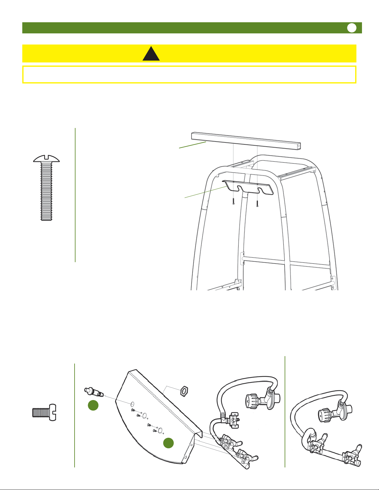
Step 7
Heat Shield Assembly
Attach the Heat Shield and the Front Side Table Support to the top of the Front U-Leg with 2) 1/4-20 x 1.5” Bolts. Insert
the bolts through the Heat Shield then the U-Leg then into the threaded inserts in the Front Side Table Support.
Front
Side Table
Support
Heat Shield
(under leg)
1/4-20 x 1.50” Bolt
2 pcs
Step 8
Manifold and Piezo Igniter Assembly
NOTE: Regulator hose is shipped attached to the Manifold.
A. Insert valve stems out through front of the Control Panel so that the holes in the valve brackets align with the holes
in the Control Panel. Fasten in place with 4) M4 x .31” Bolts through the Control Panel into the valve brackets. The
Regulator hose will be on the LEFT side.
B. Install the Piezo Igniter by first, removing the large nut shipped threaded in place on the igniter, then inserting the
igniter through the large hole on the left side of the Control Panel and fastening in place with the large nut previously
removed.
Model 6122 with
Piezo Igniter
side burner valve
Large Nut
Model 6112 without
side burner valve
B
M4 x .31” Bolt
4 pcs
A
12
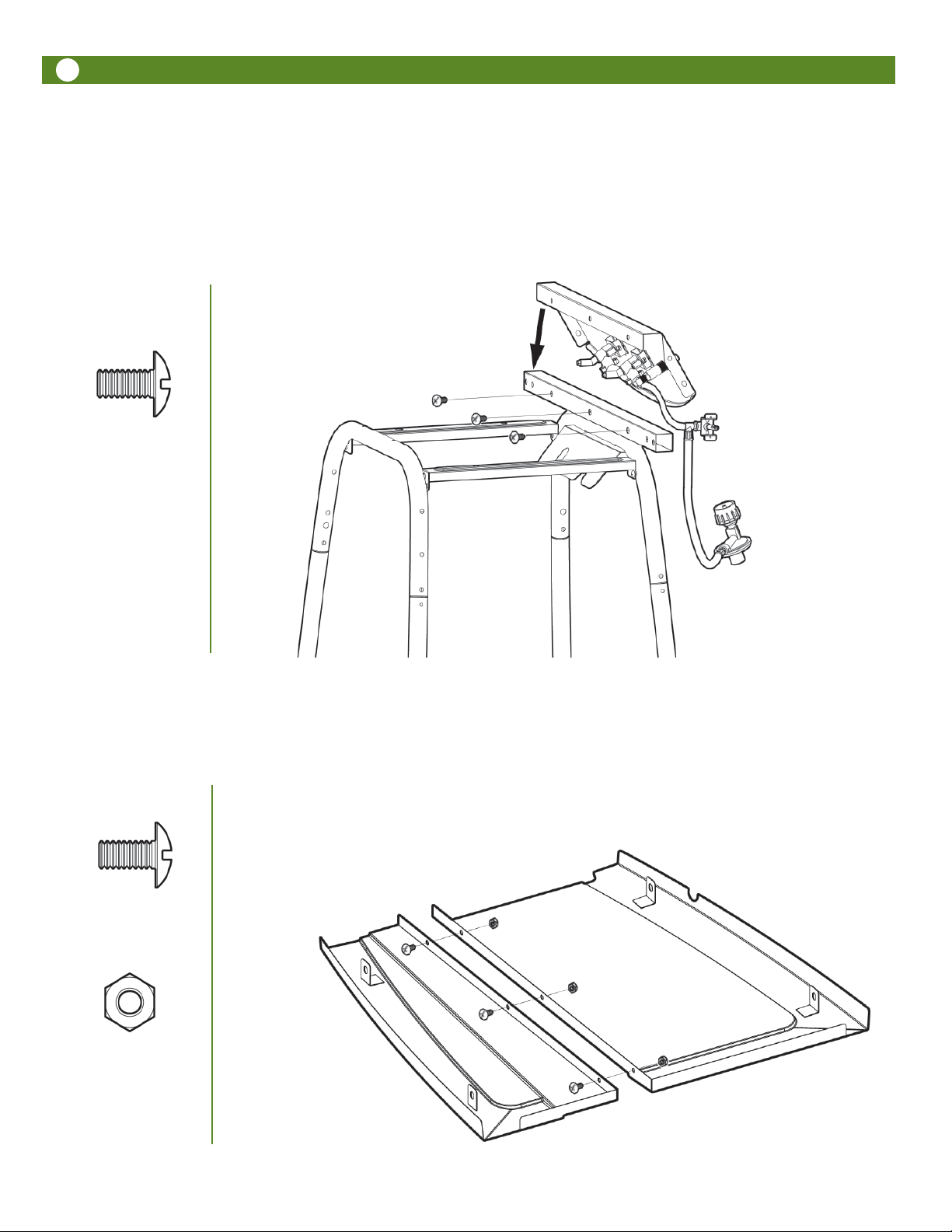
Step 9
Control Panel to Cart Frame Assembly
Place the Control Panel assembly over the Front Side Table Support tube, that is attached to the front of the Cart
Frame, as shown with 3) 1/4-20 x .39” Bolts.
Model 6122 with side
burner valve is shown
here. Be sure to route
hoses in FRONT of legs.
This configuration is for
6122 ON LY .
1/4-20 x .39” Bolt
3 pcs
Step 10
Shroud Assembly
Place the Left and Right Shroud Halves face down on the floor. Join together with 3) 1/4-20 x .39” Bolts and Nuts.
1/4-20 x .39” Bolt
3 pcs
1/4-2 0 Nut
3 pcs
 Loading...