

Page 1

M.I.G. Welder
User Guide
AUSMIG
Page 2
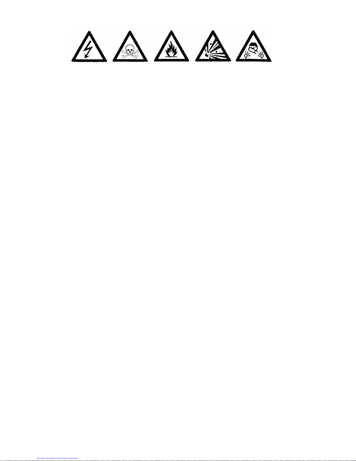
DANGER OF
ELECTROCUTION
BEWARE
OF SMOKE
AND STEAM
DO NOT USE NEAR FLAMMABLE
OR EXPLOSIVE MATERIAL
BEWARE OF
RAYS FROM
THE ARC
WARNING
WARNING:Protect yourself and others. Read and understand this manual.
ELECTRIC SHOCK: Can kill.
FUMES AND GASES: Can be dangerous to your health.
ARC RADIATION: Can injure eyes and burn skin.
* Read and understand your employer's safety practices.
* Keep your head out of fumes.
* Use enough natural ventilation, or both, at the
fume source to keep fumes and gases from the breathing zone and
the general area
* Wear correct eye, ear and body protection.
* Do not touch live electrical parts.
* Refer to AS 1674 and WTIA Technical Note 7 or the manufacturer's
recommendations for further information.
* Do not change voltage selection while the torch trigger is depressed.
* Wiring ! Select the correct primary power plug to suit the MIG
purchased.
* Disconnect MIG from power supply prior to servicing machine.
Rev:2.5
*IMPORTANT NOTICE*
AUSMIG MIG welders are covered by a Conditional Warranty.
Some Important Conditions of this Warranty are ;
* The Warranty Card Must Be Filled Out And Returned To The
Manufacturer. (If you do not have a warranty card please contact
your local Distributor.)
* Any UNAUTHORISED Tampering Or Repairs To This Machine Will
Void The Warranty. Repairs To Ausmig MIG Welders Are Only To Be
Performed By The Manufacturer Or Service Agent With Written
Authorisation.
Page 3
1
CONTENTS
Bottle Mount
page 3
Correct Gas
Regulator Assembly
Spool Assembly
Reverse Polarity
Wire Feed Rollers
Gun Assembly
page 3
page 17
page 12
page 21
page 15
page 16
page 22
page 13
page 4
page 7
- Steel / Stainless Steel
- Aluminium & Non-Ferrous
Test of Operation
Wire Tension Test
Troubleshooting
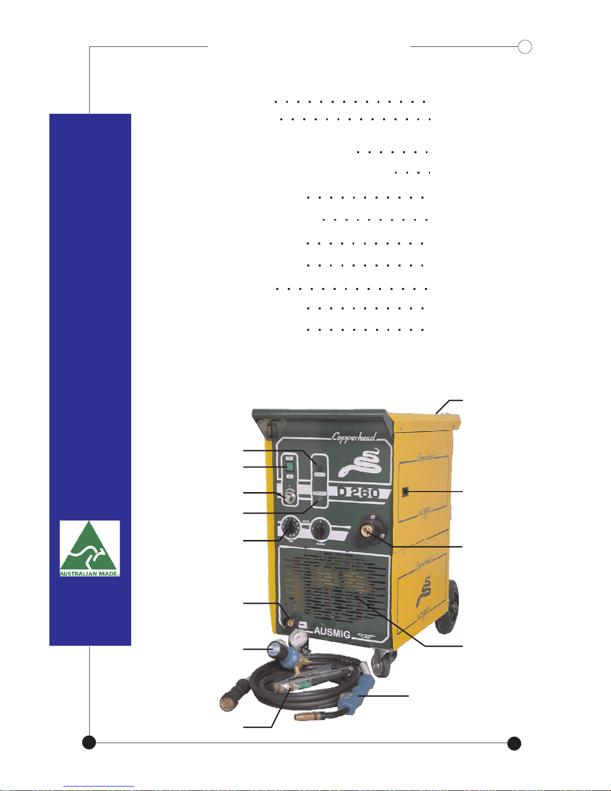
BASIC COMPACT LAYOUTBASIC COMPACT LAYOUT
Fuse 1 Amp Slow Blow
Power Switch
Wire Speed Control
OverHeat Indicator
Votlage Selection
Earth Lead Connection
Gas Regulator
Earth lead & Clamp
MIG Welding Torch
Euro Fitting Torch
Connection
Wire Drive
Compartment
Bottle Holder
Transformer
Page 4
2
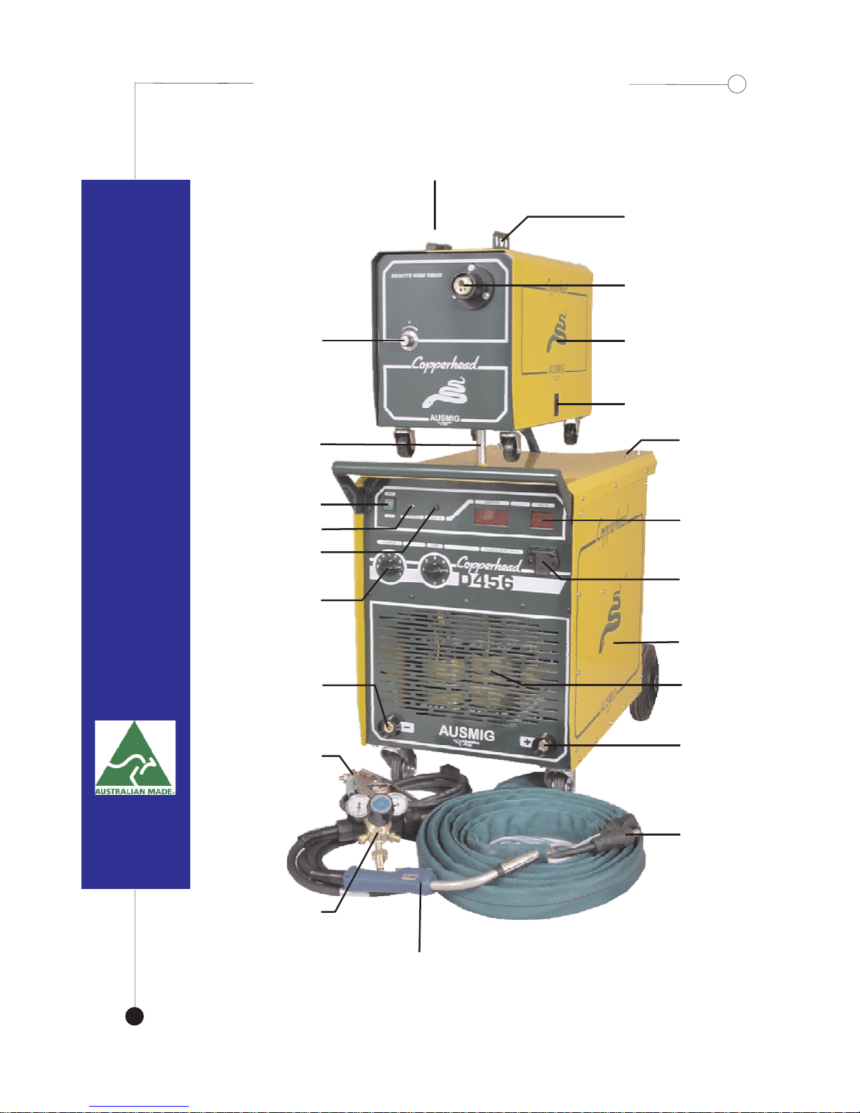
BASIC LAYOUT : TRAVELLERBASIC LAYOUT : TRAVELLER
Wire Drive
Compartment
Euro Fitting Torch
Connection
Wire Drive
Hanging Bracket
Wire Speed Control
Remote Wire
Drive
Door Latch
Removable
Mounting Post
Bottle Holder
Digital Display
Volts & Amps
Power Source
Transformer
Positive
Connection
8 Metre
Power Cable
Remote Wire
Drive Socket
Power Switch
Overheat Indicator
Fuse 1 Amp
Slow Blow
Voltage Selection
Negative
Connection
Earth Lead
& Clamp
Gas Regulator
MIG Welding Torch
Page 5
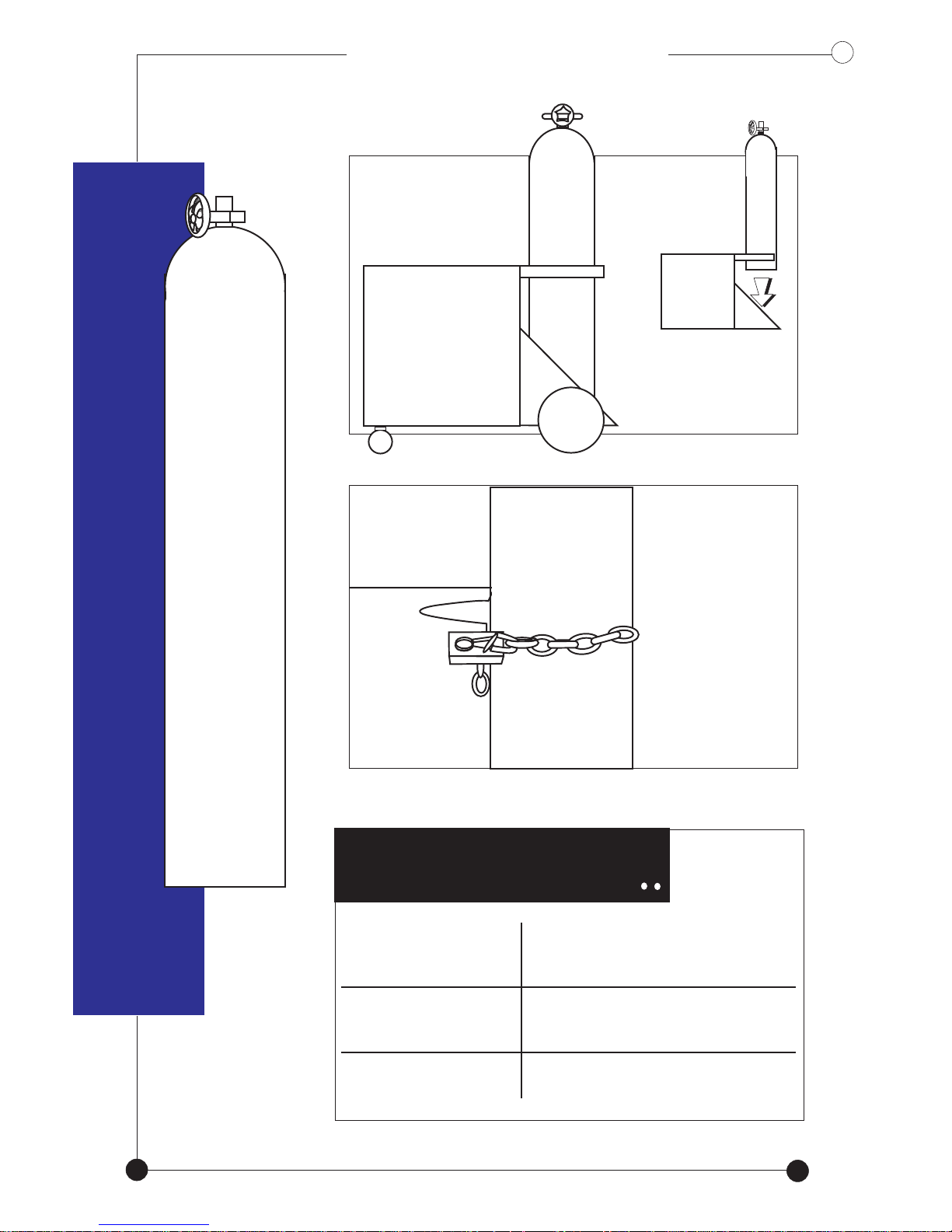
BOTTLE MOUNTBOTTLE MOUNT
Mount the bottle
on the holder
Secure
bottle with
the chain
CORRECT GAS
Stainless Steel
Steel
Aluminium
Argon Shield
Argon Shield
Pure Argon
(ARGON MIX)
(ARGON MIX)
Do not drop the bottle
onto the machine
3
Page 6
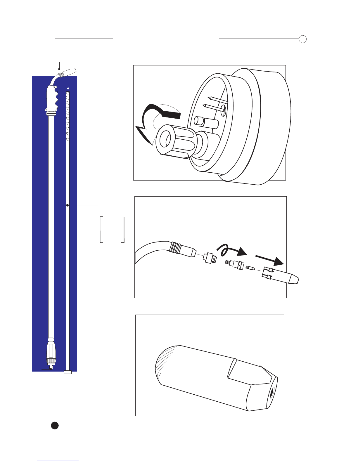
GUN ASSEMBLY
- For Steel / Stainless Steel
GUN ASSEMBLY
-
For Steel / Stainless Steel
liner (A)
torch
Check
for
any
kinks
Remove liner
positioning
nut.. *A*
Lay gun and
liner straight
4
LINER
Ensure that the correct
tip is fitted for the
wire being used.
Disassemble
torch head..
Unscrew
Pull out
A
Page 7
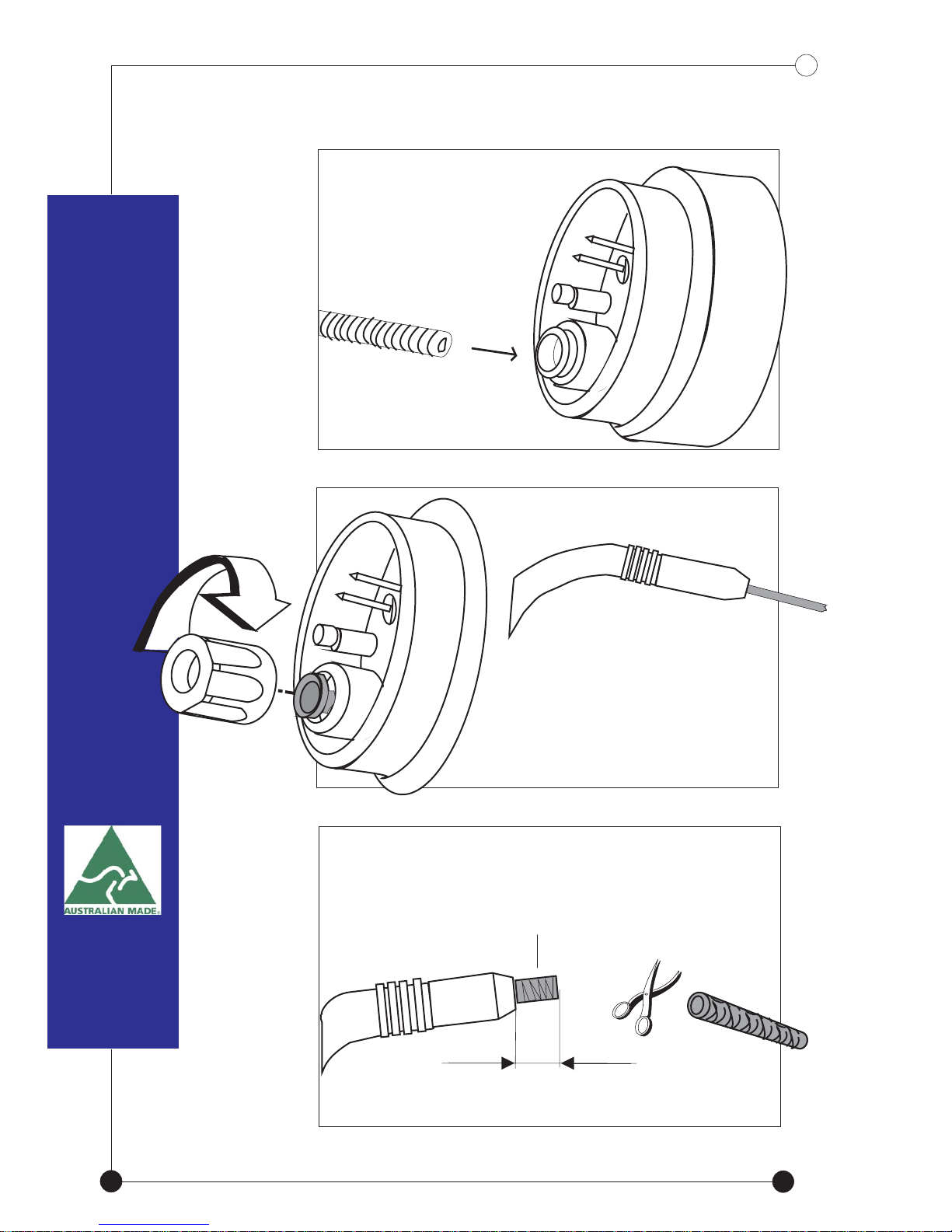
GENTLY feed
liner fully through
the euro fitting of
the torch
Screw positioning
nut back tightly but
Cut excess liner leaving
2mm from the gun neck
liner.
2mm
over tension.DO NOT
5
Page 8
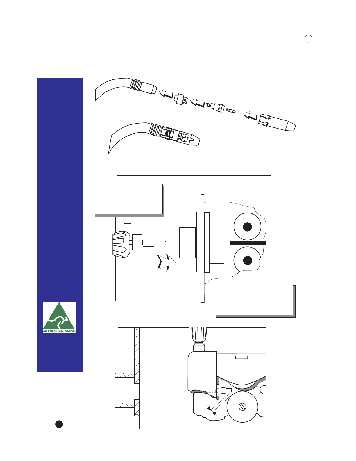
Re -assemble
torch head
Slide nozzle on firmly
Euro fitting
*Slide Together*
Do not
allow the
guide tube
to touch
rollers.
Leave 2mm
gap between
the two.
6
Align the torch
and Euro Fitting.
Screw in the collar
until it “bottoms”.
Do not overtighten
Page 9
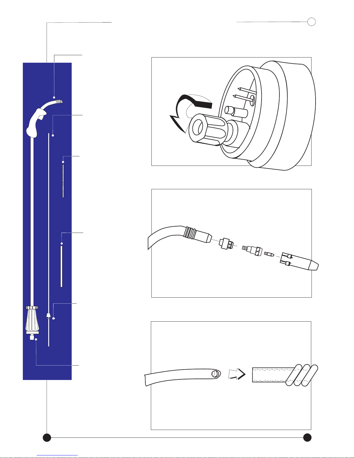
A
GUN ASSEMBLY
GUN ASSEMBLY
- For Aluminium & Non-Ferrous
- For Aluminium & Non-Ferrous
TORCH
Unscrew liner
positioning
nut (E)
TEFLON
LINER (A)
BRASS
NECK
LINER
BRASS
TUBE
SECURING
(B)
(C)
Remove steel
liner if fitted
Disassemble
torch head
COLLET
LINER
POSITIONING
NUT
Lay gun and liner
out straight
(D)
(E)
Teflon
liner (A)
Screw liner into brass spring
neck tightly on the opposite
end from the securing collet
Brass spring
neck liner (B)
7
Page 10
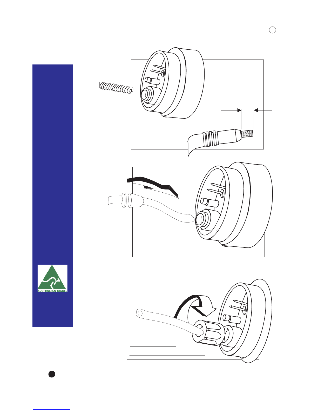
GENTLY feed the
connected insert
fully through until
2mm is
protruding from
the gun head
Slide securing
collet & washer (D)
through to the end of the euro fitting
Screw back positioning
nut (E) through the liner
*Do Not Overtighten*
DO NOT CUT
EXCESS LINER YET!!
2mm
(B)
8
Page 11
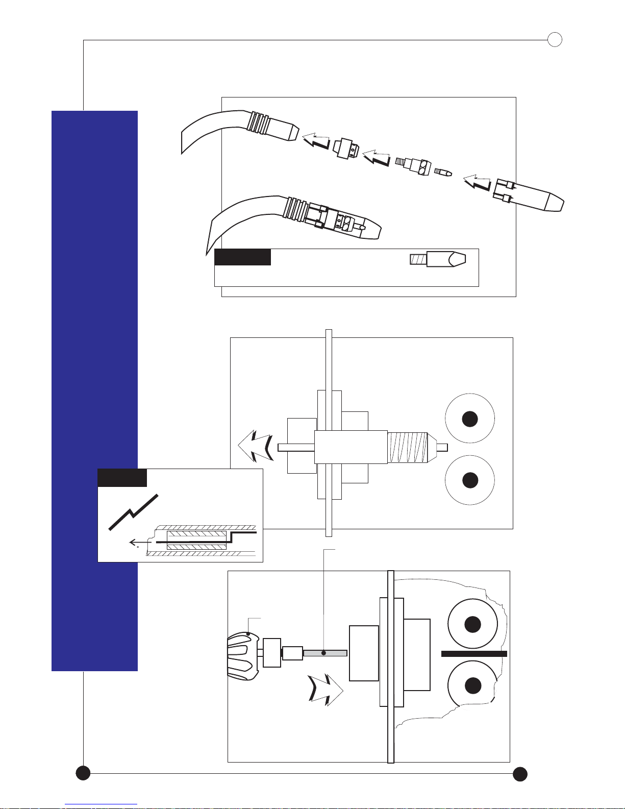
Re -assemble
torch head
TIP..
NOTE
You MUST use aluminium contact tip
use a piece of mig
wire to hook and
remove steel guide
tube
ALUM
Remove steel guide
tube from feed roller
TEFLON
LINER (A)
TORCH
Connect euro fitting
to mig machine
9
Page 12
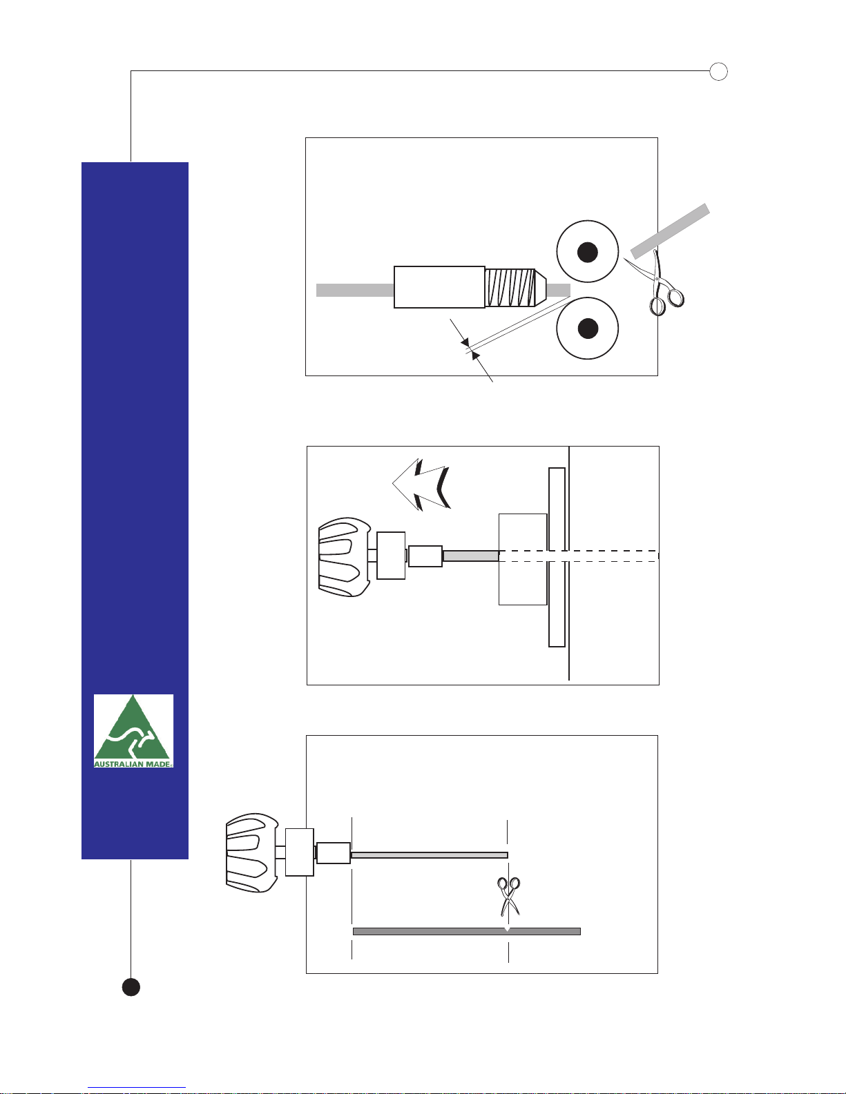
2mm
Cut excess liner ensuring a
2mm space is left
between roller and liner
Remove torch to align
brass tube
LINER
Using a hacksaw, cut brass
tube (C) to exactly the same length
as the protruding liner
10
Page 13
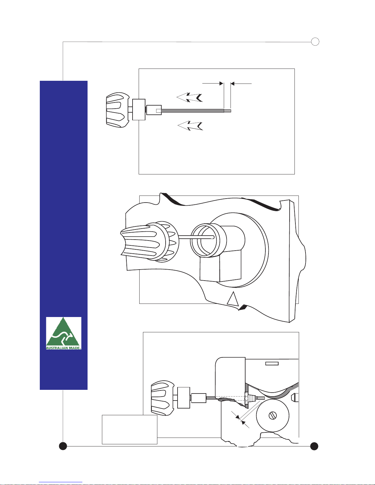
Reconnect
euro fitting
to mig machine
Check that 2mm gap is between
the liner and the roller. DO NOT
let them touch.
2mm
Slide the brass tube over the
liner until 2 mm of the
liner protrudes from the neck
11
Ensure a “U”
Groove Roller
is fitted.
* Do not overtighten*
Page 14
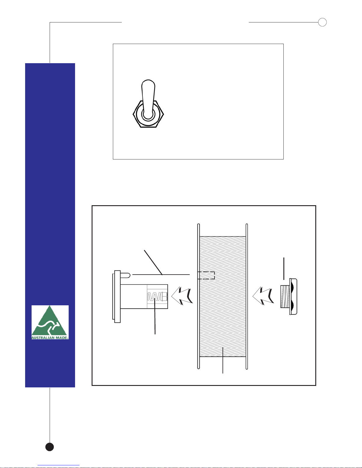
TOGGLE SWITCHTOGGLE SWITCH
Select the appropriate
wire speed for your
Steel
application.
Slow speed for Steel.
Fast for Aluminium.
The Switch is located
Alum
on the back of the unit.
WIRE SPOOL ASSEMBLYWIRE SPOOL ASSEMBLY
Locating Pin
Locking Nut
When fitting a spool of wire, ensure that the
locating lug is correctly aligned with the spool.
Do not overtighten the locking nut.
12
Spool hub
Adjustment
15 Kg Wire Spool
Page 15
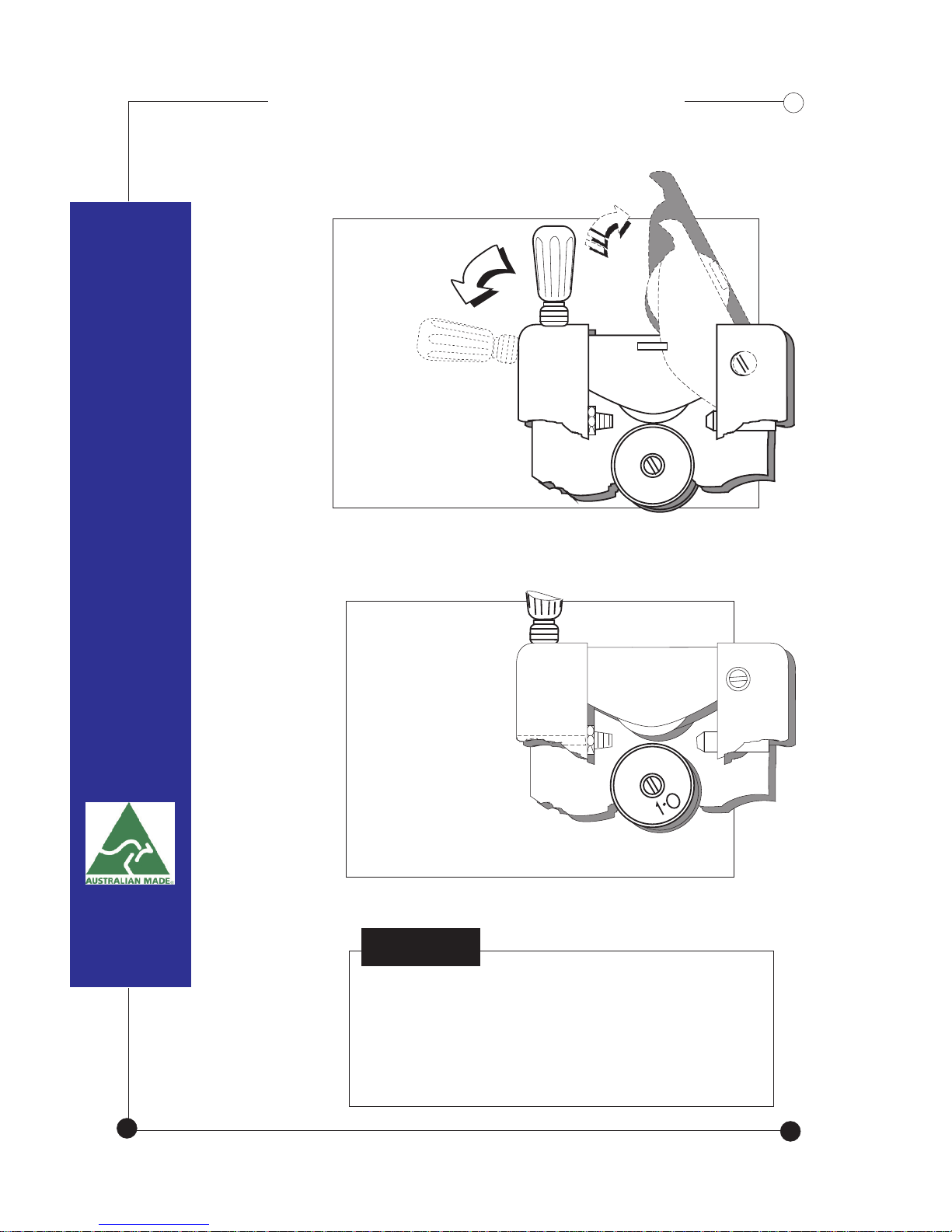
Release
Wire-Drive
Tensioner
WIRE FEED ROLLERSWIRE FEED ROLLERS
NOTE
Liners should be blown through with
compressed air every time a roll of
wire is replaced .
Install the
appropriate
drive roller to
match the selected wire.
13
Page 16
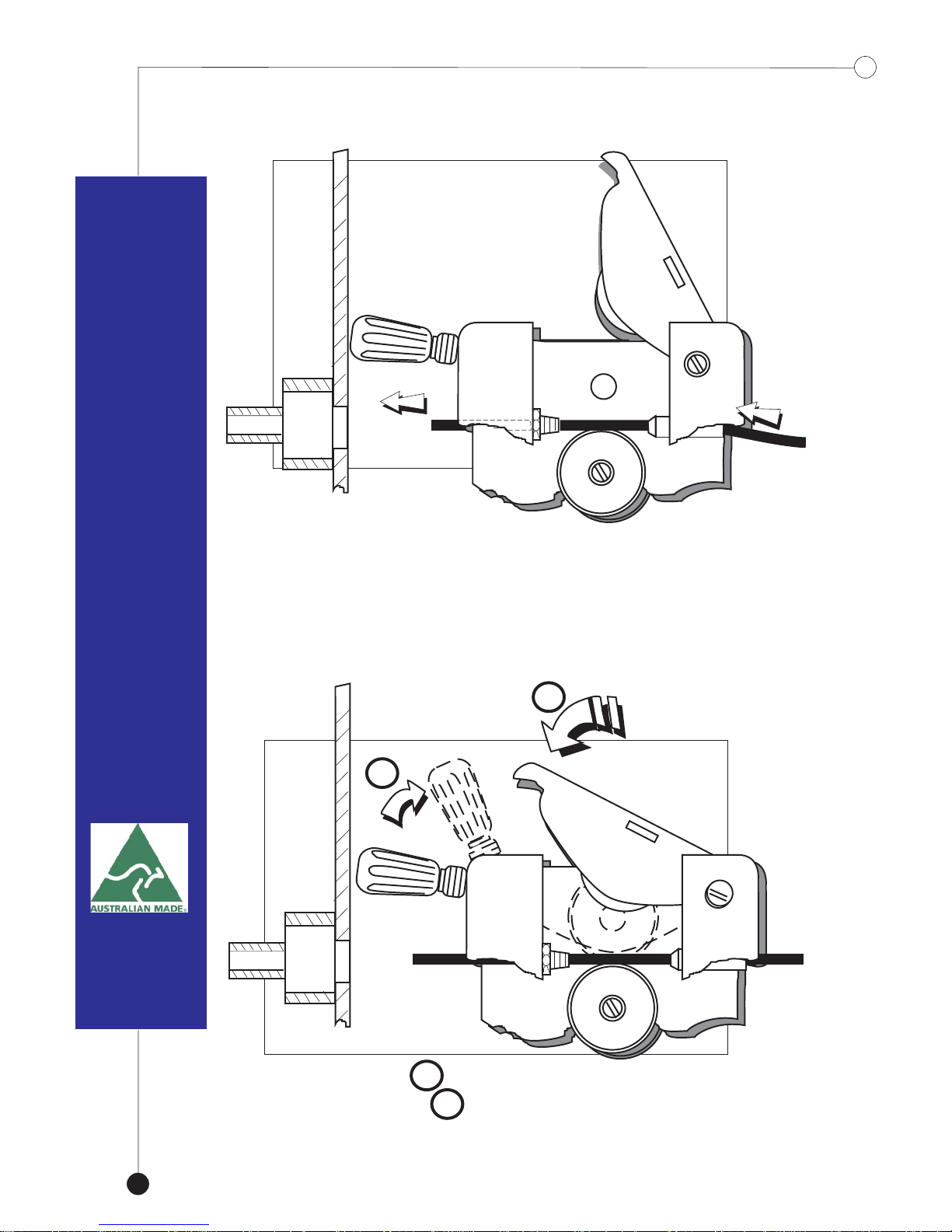
Feed wire through
until it is 30mm
into the guide tube
2
Return roller 1
then tensioner 2
1
14
8
Page 17
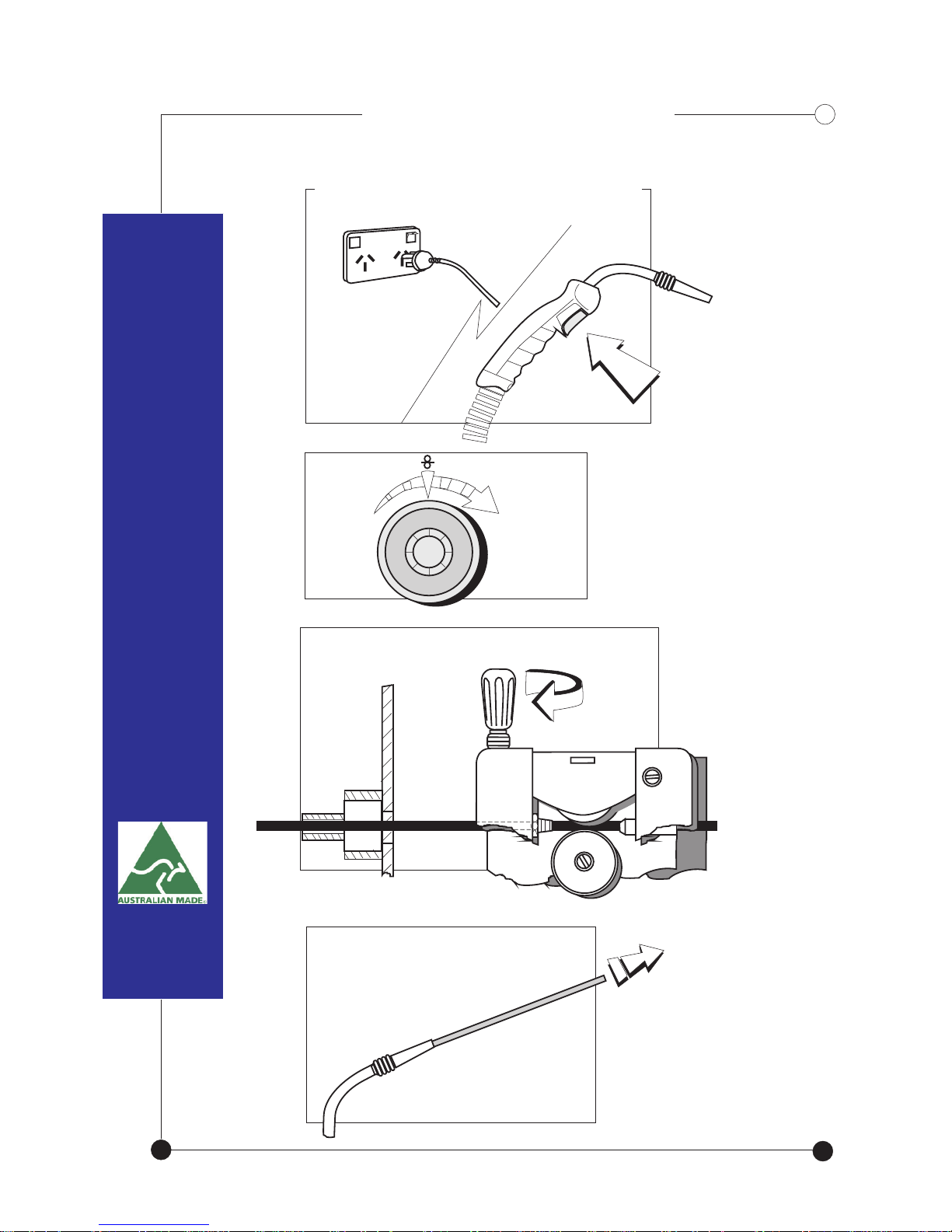
Startup ProcedureStartup Procedure
Keep trigger depressed
until wire protrudes out
from the gun head at
approximately 300mm
Twist tensioner until wire begins
to roll through
Plug into mains, switch machine on
Depress &hold trigger down
Adjust wire
speed control
knob to start
wire drive rollers
1
2
3
4
5
6
9
8
7
15
Page 18
16
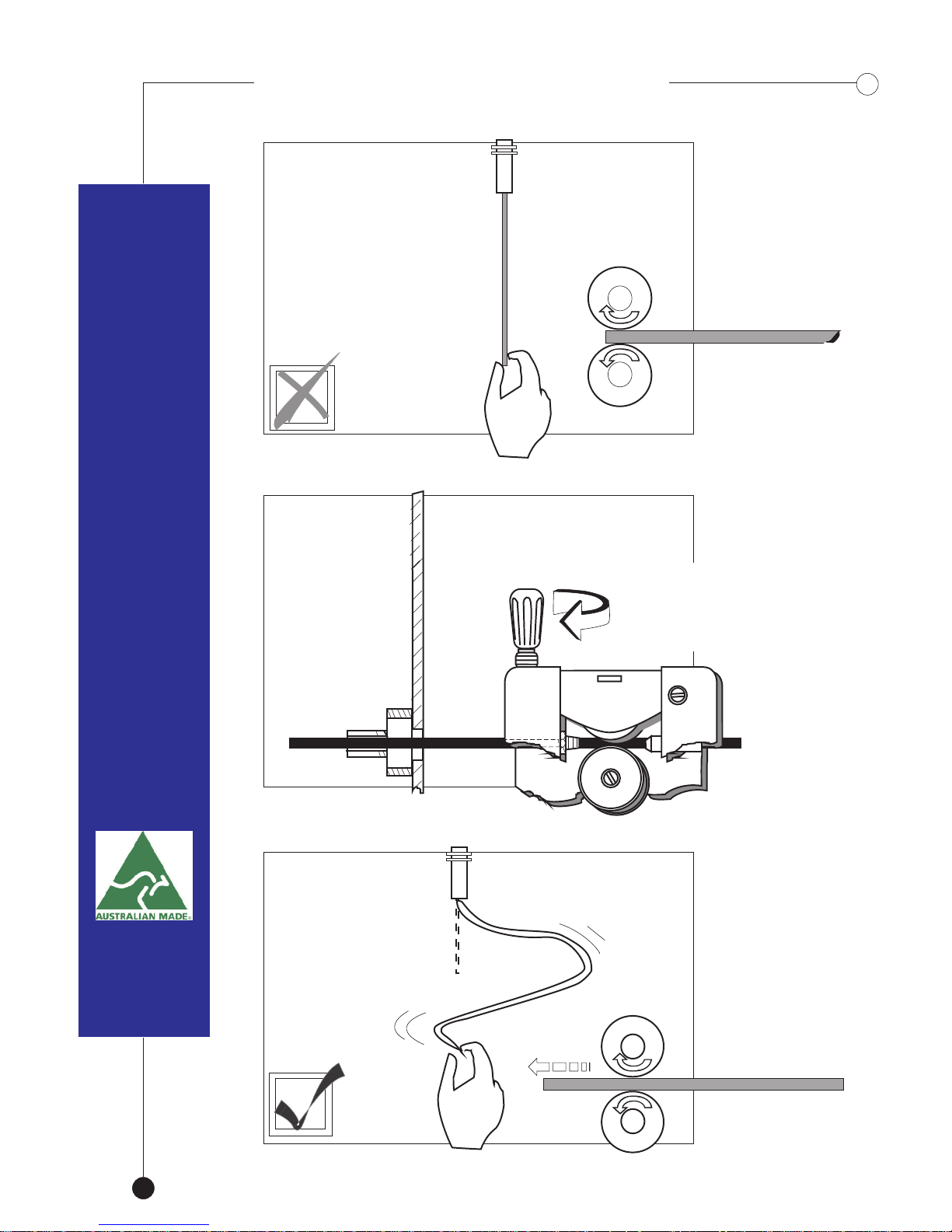
Twist tensioner
accordingly.
If wire slips
through the
rollers.. Not
enough tension
No wire
movement..
Gun head
Wire sways
and runs
through the
rollers without
slipping
Hold wire
WIRE TENSION TEST
Continuous
feed..
16
3 ~ 3.5 Maximum
Check setup if more
is required.
Page 19
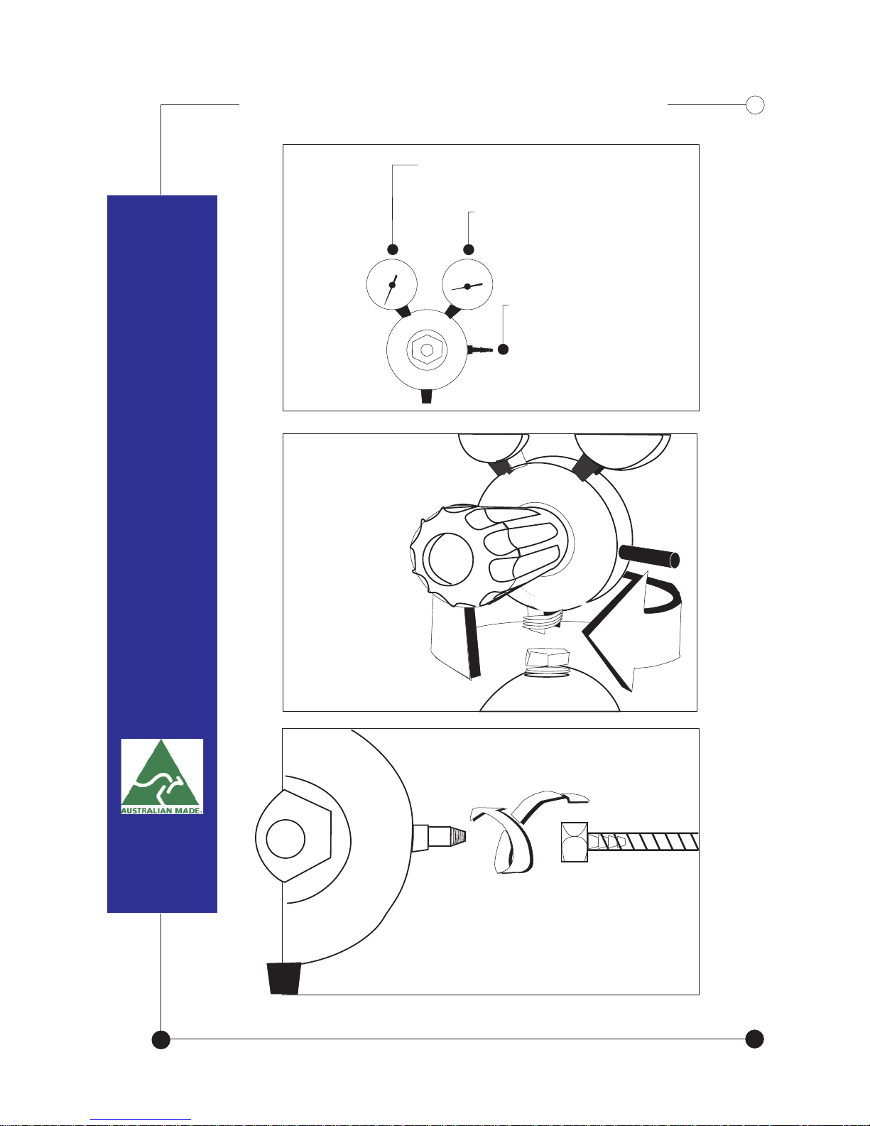
REGULATOR ASSEMBLY
Screw regulator
onto gas bottle
17
Screw nut & tail
with gas hose connected
to the regulator.
Remaining gas
Flow rate.
Gas Outlet.
Page 20
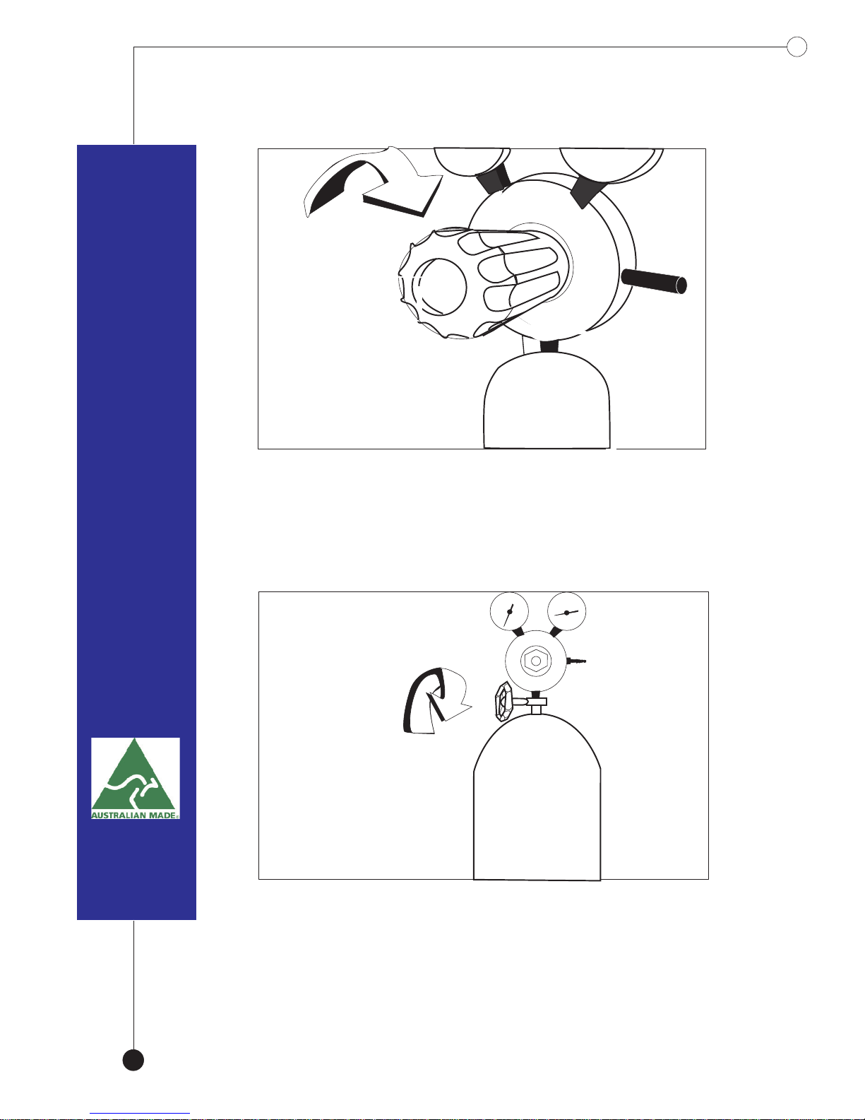
Slowly open the gas bottle valve.
18
Screw in pressure adjustment knob
until slight resistance is felt.
Page 21
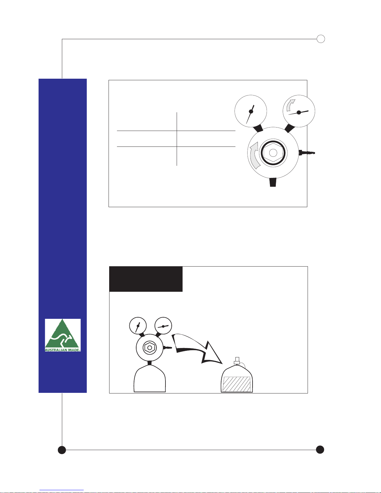
NOTE:The more the control knob
is screwed in, the higher the flow rate
Adjust control knob according
to the desired flow rate
STEEL
STAINLESS STEEL
ALUMINIUM
10-15 l/min
10-15 l/min
15-25 l/min
When exchanging bottles,
be sure to turn flow rate
control knob all the way to the left to protect
diaphragm inside the guage from damage.
TIP ..TIP ..
19
Page 22
Typical Control SettingsTypical Control Settings
20
Use low voltage selection and low
wire speed for light and thin
materials.
Increase voltage and wire speed
as material thickness increases.
MACHINE MAINTENANCE
DO NOT OPERATE THE WELDER WITH
THE SIDE PANELS REMOVED.
Grinding Dust is the greatest enemy of any machine
and the frequency for cleaning your machine is
dependant on the environment you are working in.
After disconnecting the machine from its power source,
remove the side panels, and with compressed air remove
any dust from the transformer windings, diode pack, fans
and switches etc.
Other Key components to inspect are :
Spool Post ~
Check for Tension / smooth operation
Grease periodically
Earth Lead ~
Broken / frayed cabling
Damaged / burnt clamp
Torch ~
Damaged lead
Worn tip / Diffuser / Tip holder / Nozzle
Do not touch components or wiring
while panels are removed.
Drive System ~
Tension (Average setting 3)
Drive rollers - check for wear
Guide tube alignment / wear
*DO NOT LUBRICATE*
Page 23
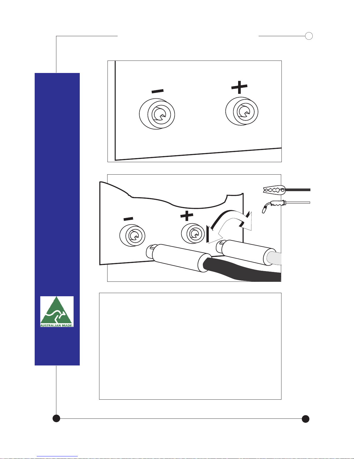
REVERSE POLARITYREVERSE POLARITY
21
For wires that require reverse polarity,
exchange the two cables around .
Positive (+) to negative (-),
Negative (-) to positive (+).
Only available as standard
equipment on TRAVELLER models;
Optional on compact machines .
Page 24
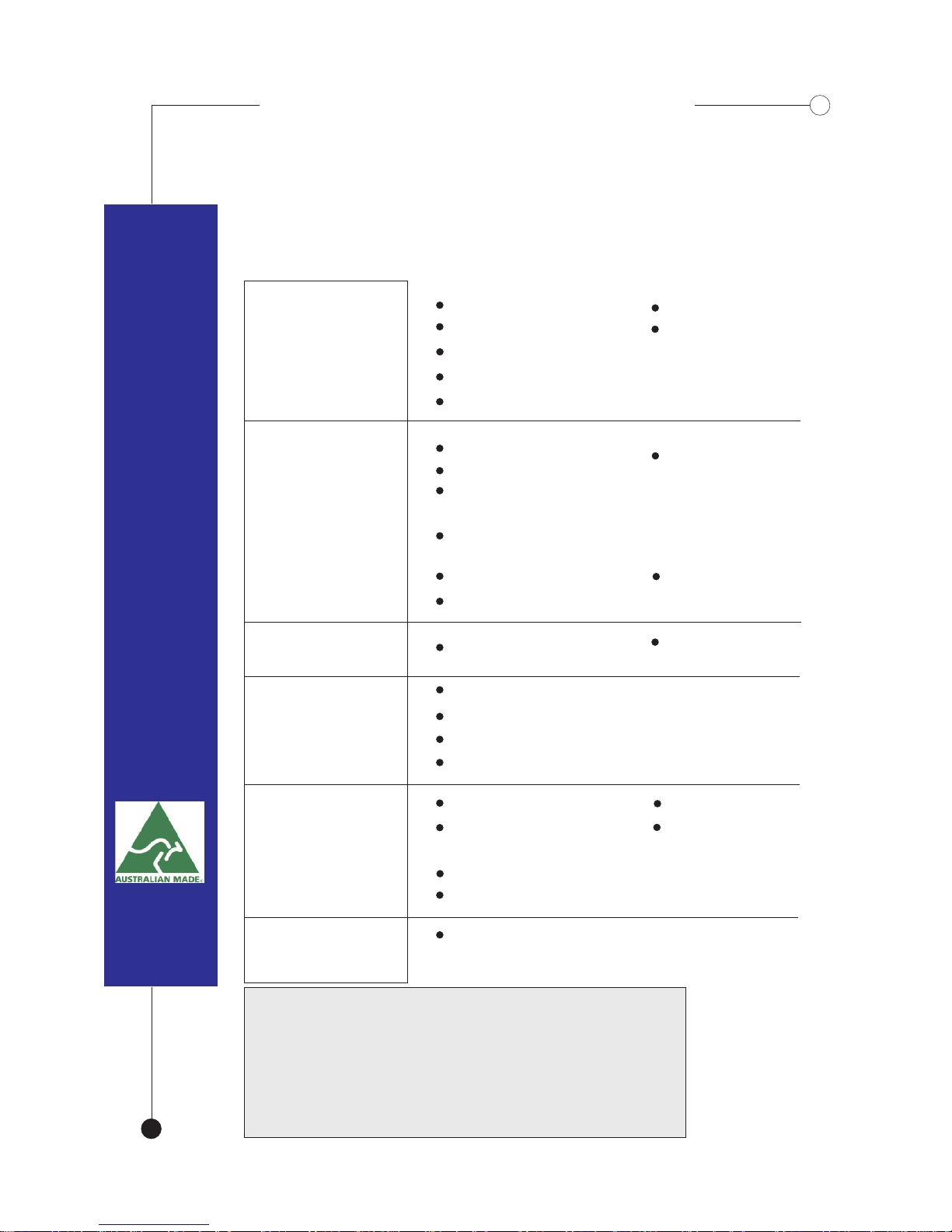
TROUBLE SHOOTINGTROUBLE SHOOTING
Symptom
Possible Causes & Solution
Possible Causes & Solution
Too porous,
bubbly..
Faulty gun
Windy area
Faulty gauge
Insufficient or out of gas
Rusty or Contaminated material
Dirty liner
No liner
Large build-up
(3-phase only)
phase out
or
diode out
Incorrect polarity
Poor power
Long extension
lead
Loss of power
Wire speed
too fast
No Penetration
Loose cables
Incorrect polarity
Tighten rollers
Exceeded duty cycle
Thermal protection cutout
Loss of primary power
Wrong size rollers
Not enough wire
tension
Wrong size tip
Liner cut too short
Wire Slips
Machine not
running
Wire burning
through to the
tip
(sticks to it)
Dirty liner
Dirty liner
Incorrect roller
size
22
Spool hub
needs tensioning
Wire jumps off
spool
MIG WELDERS ARE A QUALITY
AUSTRALIAN MADE PRODUCT.
FOR MORE INFORMATION PLEASE CONTACT,
AUSLINK WELDING EQUIPMENT P/L
23 RESEARCH DRIVE CROYDON
PH 03 9761.4915 FAX 03 9761.4916
AUSMIG
Blown Fuse
Liner is kinked
 Loading...