

Page 1
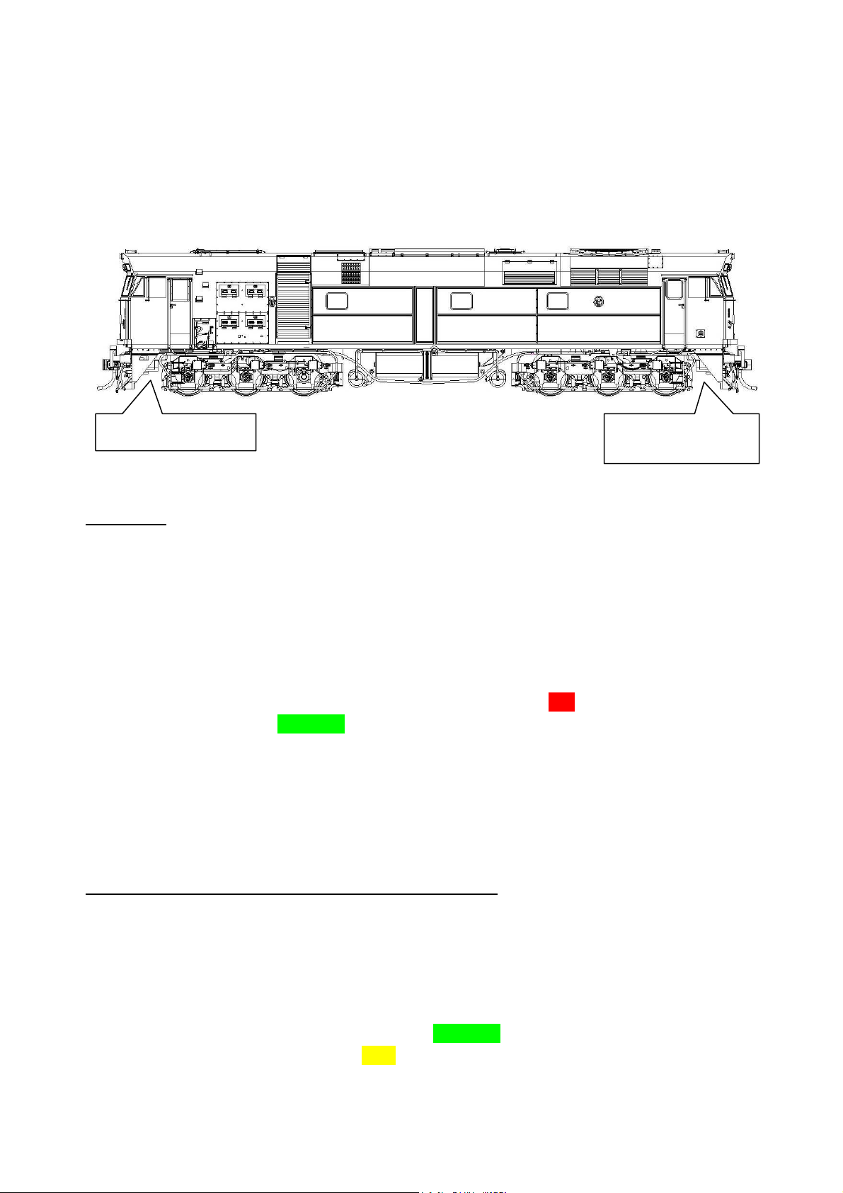
Auscision Models 442 Class Operating Information.
Number 1, Front End.
Number 2, Rear End.
‘Radiator Fan End’
Your Auscision Models 442 class locomotive’s main printed circuit board and associated lighting has been
designed to function as a DC and DCC Sound Decoder Installed Model. In these notes reference is
made to the No.1 end and No.2 end of the model. This diagram will assist in identifying which end
is which:
DC Model
The DC model is able to control the locomotives lighting via the micro switches on the bottom of the
fuel tank. The lighting is directional. The switches are able to isolate, turn on/off:
The lighting connection for the DC model has the Number 1 and Number 2 end white/red marker lights
connected to the main printed circuit board at the two plugs marked ‘DC’. The Headlights and Number
Boards connection is via a COMMON wiring plug that both the DC and DCC Sound Decoder Installed
versions use. (See image on page 3)
If you’re going to operate your model on a DC system /controller then read no further. If you plan on
fitting an after marker decoder or your model is a DCC Sound Ready model please read on.
1. The Locomotives Headlights.
2. The Locomotives Number Boards and White Marker Lights.
3. The Locomotives Red Marker Lights.
DCC Ready Model - fitting an aftermarket decoder
The 442 class models main printed circuit board has been specifically designed to function through the
‘NEM660 standards’ 21pin connector and integrate with the new ESU Loksound V5 decoder. Via the 21
pin connector this decoder functions with four individually powered auxiliary outputs (Headlight front,
Headlight rear, Aux 1 and Aux 2) and four individual logic outputs (Aux 3, 4, 5, 6) which the main circuit
board has electronic components included for their operation. The DCC Sound Decoder Installed
models lighting connects via 3 separate plugs. One COMMON connection for the Headlights and
Number Boards, and two plugs marked ’DCC’ for the appropriate ends marker lighting. (See image on
page 3)
Auscision 442 Class Operating Information (v3) Page 1 of 9
Page 2
When selecting an aftermarket decoder a few details may need to be considered first. As there are two
standards of decoder 21pin connections available on the market, the NEM660 version and the NRMA
version, two lighting connection possibilities are available on the Main PCB.
Specifically, for the models White/Red Marker Light connection for both ends, the plugs marked ‘DC’
and ’DCC ’ are available (See image on page 3). The lighting connection will be dependent on the brand
and version of the aftermarket decoder being used. Generally speaking any aftermarket 21 pin decoder
can be fitted.
For aftermarket decoders with a reduced number of auxiliary lighting outputs, the Locomotives
Reversible Headlights along with Aux 1 (Front Number Boards, Front White Marker Lights, Rear Red
Markers lights) and Aux 2 (Rear Number Boards, Rear White Marker Lights, Front Red Markers lights)
will function as long as the Marker Lighting is connected to the ‘DC’ PCB plug connection.
Note: Using just the 2 Auxiliary outputs the Lighting functions can also be isolated with the micro
switches on the bottom of the fuel tank. (E.g. turning the opposing end, red marker lighting off).
Alternatively refer to the link below for further decoder possibilities. This is an excellent source of
information which addresses the 21pin NEM660/NMRA standards and their associated differences and
functionality issues, along with a chart identifying which other brand decoders and versions that may
also be suitable.
http://www.sbs4dcc.com/tutorialstipstricks/21mtcconnector.html
Fitting the decoder - once the model's body is removed from the chassis, taking care with the body’s
wiring and COMMON lighting connection plug, first remove the small 21pin DC adaptor PCB from the
main PCB’s 21 pin plug. Removal of the DC adaptor PCB also removes the components associated with
motor noise suppression for DC function. Then, and paying close attention to the pin alignment, firmly
push the decoder onto the 21 pin plug.
Note: Alter the DC/DCC plug connections for Marker Lighting if required. Inadvertently plugging the
lighting into the wrong plug should pose no risk to damaging any circuitry, although care should be
taken ensuring the lighting is connected to the correct plug for the decoder that has been selected.
Speaker connection is via the supplied connector plug/wiring harness, fitted to the plug marked ‘SP’ (see
image on page 3). Keep in mind matching the chosen speaker and decoder’s amplifier impedance.
ESU Loksound V5 DCC Decoder Installed Model
Your DCC Sound Installed Model is fitted with the recently released ESU Loksound V5 Decoder. All
switches on the bottom of the fuel tank are to remain in the turned on position. The Decoder connects
to the main printed circuit board via the 21pin connector, with the lighting wiring connecting via three
plugs at the main PCB (see image on page 3):
• The Headlights and Number Boards connecting from the locomotive body at the COMMON plug
• The white/red marker lighting via the two plugs marked ‘DCC’ for the appropriate end.
The decoders default settings have been adjusted to ensure your model operates smoothly straight out
of the packaging. Please take a moment to read through the following information as it relates to the
functionality and features along with further information as to individualising your model.
Auscision 442 Class Operating Information (v3) Page 2 of 9
Page 3
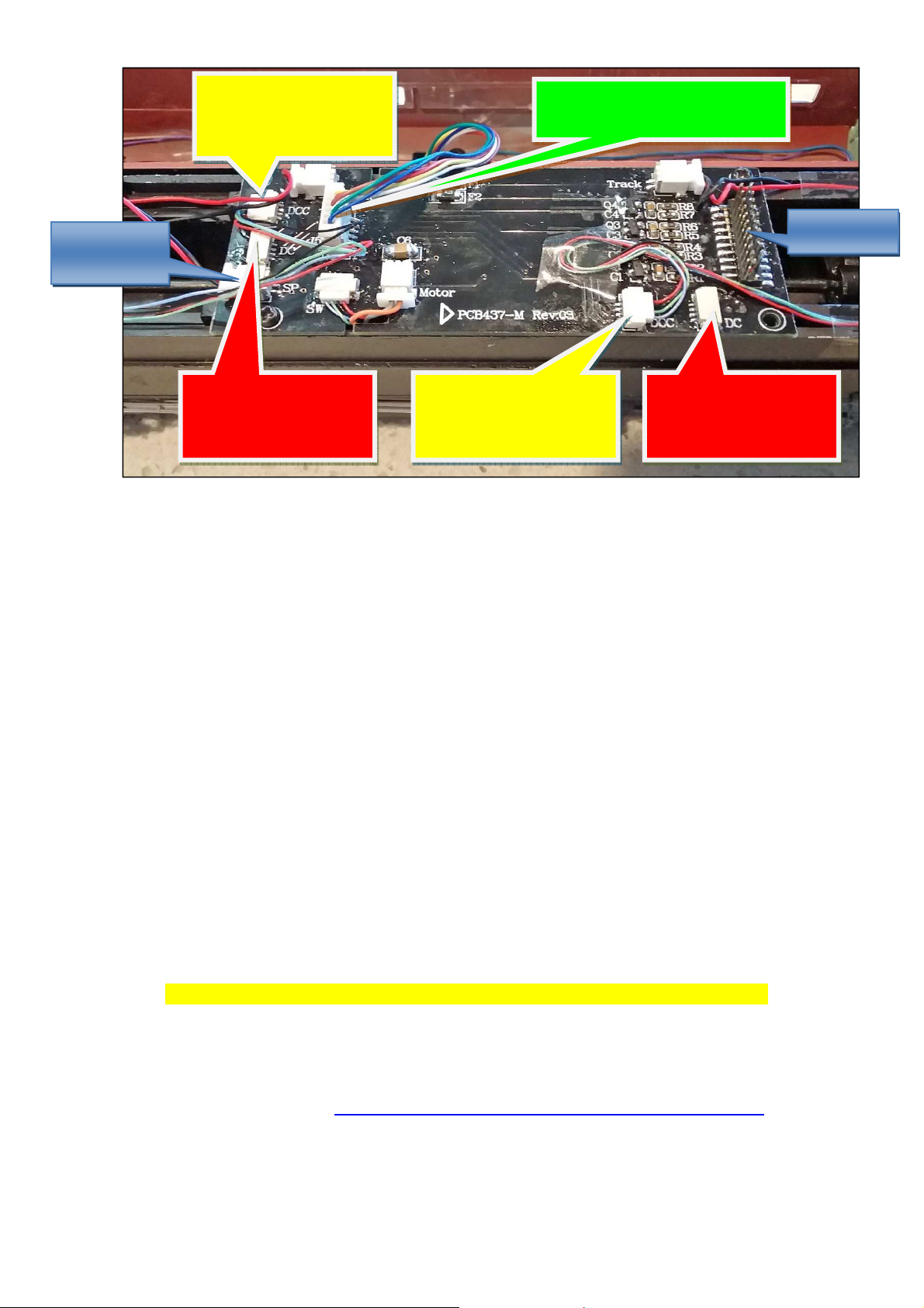
#2 End Marker Light
#1 End Marker Lights
#1 End Marker Lights
#2 End Marker Lights
Common Headlight and Number
Board Co
nnection Plug
Speaker Plug
‘SP’
21 Pin Plug
DCC‘ Sound Installed
Version Connection
DC Version Connection
Plug
• In order to adjust the running qualities of your model for your personal preference, reference to
suggested settings in the form of a quick start guide is available in the following notes. Alternatively
for full decoder adjustment details refer to the ESU Loksound V5 Decoder Manual and Full Throttle
Description available at the following links:
http://www.esu.eu/en/downloads/instruction-manuals/digital-decoders/
http://www.esu.eu/en/products/loksound/loksound-full-throttle-diesel-features/
A description of the ESU 96429-LSV5.0DCC-Diesel-Auscision-Models-442-Class-FT-V4 and link to
download the default file can be found here:
http://projects.esu.eu/projectoverviews/19
• If required, adjustments and individual finetuning of your DCC model and decoder can be made
primarily in two ways.
1. The most simple and effective way is with an ESU Lokprogrammer interfaced with a Windows
operating system PC.
The details of which can be found here:
Note: An updated software version to function with the V5 decoder will be required.
DCC Sound Installed
Version Connection Plug
DC Version Connection
Plug
Product Information... http://www.esu.eu/en/products/lokprogrammer/
Instructions................ http://www.esu.eu/en/downloads/instruction-manuals/lokprogrammer/
Updated Software...... http://www.esu.eu/en/downloads/software/lokprogrammer/
2. Alternatively adjustments can be made via your DCC operating system controller or with other PC
based software such as JRMI. Refer to your operating system manual and the ESU V5 decoder
manual.
Auscision 442 Class Operating Information (v3) Page 3 of 9
Page 4

Quick Start Guide
Care has been taken in order for your model to perform straight out of the packaging. In general it
has been programmed to ESU Loksound’s V5 Decoder default values. As modellers we all have
different ideas and preferences as to how our models perform. Should you wish to further adjust how
your model performs, the following is a quick start guide to some of the primary settings required to
do so.
Excerpts from the ESU Loksound V5 and Lokprogrammer references are included in the description
and are as follows. (Refer to the V5 Decoder Manual, the Lokprogrammer Manual or your DCC
systems programming section for full programming details)
The Default Locomotive Address for your 442 class model is 3.
•
In order to change the locomotive address, refer to chapter 9.1, 9.2 ‘Address Settings’ of the ESU
V5 Decoder Manual. Individual DCC controller systems may also have a programme track output
and function available for this purpose.
Decoders operating within a DC operating system will function as per ESU’s default DC settings.
•
For further detail also refer to the DC notes contained within our 48 class operating information
document found here:
http://www.auscisionmodels.com.au/PDFs/Auscision%20HO%20Scale%2048830%20class%20DCC%20Operating%20Information%20v4.pdf
Motor Auto Tune Procedure
Should you encounter any running performance issues the following Auto Motor Tune procedure may
help resolve the problem.
This feature will automatically adjust the Motors Back-EMF in most cases. This is not meant to be a
“cure all” solution. In most cases this will be all that is required, however there still may be the need to
perform some manual adjustments.
In order to use this automatic adjustment you will first need to place your locomotive on a section of
track paying attention to the set direction of travel. Set CV 54 to a value of 0. Activate function F1. (Be
sure to have plenty of clear space ahead of your locomotive. Allow 2 metres of available track) Your
locomotive will quickly take off at full speed and then stop while reading the motor responses. This will
automatically set the motor values required in CVs 52, CV 53, CV 54, and CV 55. From here you can
make any other manual adjustments if needed.
Refer Loksound V5 manual, chapter 11 for full motor adjustment details.
Minimum and Maximum Speeds
As default, the decoder will automatically detect the user’s controller speed step settings, with the
controller using 14, 28 or 128 steps (28 being common).
• Default is the Exponential 1 28 step speed table as per the graph below utilising minimum and
maximum speed settings.
• Defaults are CV2 =3 (minimum speed value) and CV5 = 255 (maximum speed value).
Auscision 442 Class Operating Information (v3) Page 4 of 9
Page 5
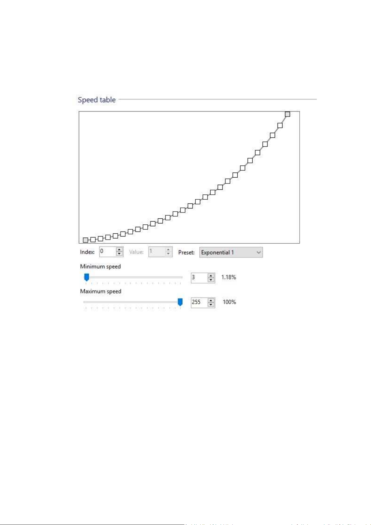
• These two values define the compression of the curve while automatically adjusting the 28
individual speed steps in between that make up the curve. Alternatively and using Lokprogrammer
there are several other speed preset tables available, as well as being able to adjust each of the 28
individual speed steps by changing the values at CV67 through to CV94 with values in the range
between 1 and 255. Full details can be found in Chapter 10 ‘adaptive driving behaviour’ of the
Loksound V5 instruction manual.
Acceleration Momentum and Deceleration Momentum
The models acceleration momentum time and deceleration momentum time can be adjusted
individually.
The time for accelerating from 0 to maximum speed is adjusted in CV 3 (default value = 22, which
equates to 19.71 seconds) while deceleration is set in CV 4 (default value = 22, which equates to 19.71
seconds). Value Range is from 1 to 255 or from 0.9 to 228.48 seconds. (Approximately 0.89 seconds
for each increment of value)
The times set in these CVs work speed dependant. Therefore, the acceleration distance and the brake
distance are longer at higher speeds. In other words, the faster the locomotive moves, the longer the
distance until it stops.
Auscision 442 Class Operating Information (v3) Page 5 of 9
Page 6

DCC Function Table
F0 Directional Headlights
F1 Not in use. For future applications
F2 Playable Air horn
F3 Drive Hold (Full throttle feature)
F4 Dynamic Brake
F5 Locomotive Brake (Full throttle feature)
F6 Headlight Dimmer Control
F7 Front Number 1 End. Marker Light and Number Board Logic (See notes below)
F8 Prime Mover Locomotive Sound (Start/Stop)
F9 Rear Number 2 End. Marker Light and Number Board logic (See notes below)
F10 Manual Coupler sounds
F11 Coast (Full throttle feature)
F12 Run 8 (Full throttle feature)
F13 Manual Cooling Fan on/off
F14 Acceleration / Shunting mode (Turns off any momentum settings. Runs at half speed)
F15 Volume Fade Control (set at 50% normal volume level - ideal for loud multiple unit
consists)
F16 Manual Sanding Valve on/off
F17 Manual Compressor on/off
F18 Brake Set / Brake Release (Default is on. Automatically Brake Valve Sound plays when
moving off or stopping)
F19 Not in use
F20 Not in use
F21 Headlight, #1 / Front End (not directional)
F22 Headlight, #2 / Rear End (not directional)
F23 Number Boards #1 / Front End
F24 Number Boards #2 / Rear End
F25 White Marker Lights #1 / Front End
F26 White Marker Lights #2 / Rear End
F27 Red Marker Lights #1 / Front End
F28 Red Marker Lights #2 / Rear End
Auscision 442 Class Operating Information (v3) Page 6 of 9
Page 7
Random Sounds
With previous Loksound Select and V4 decoders Random Sounds such as ‘Compressor’ were turned on
as default and would start and stop automatically. The parameters within the sound flow in most cases
made it difficult to alter their condition.
The V5 decoder along with the updated Lokprogrammer software allows more flexibility to control
random sounds. The default 442 class sound file has NO ‘Random Sounds’ turned on. The following is
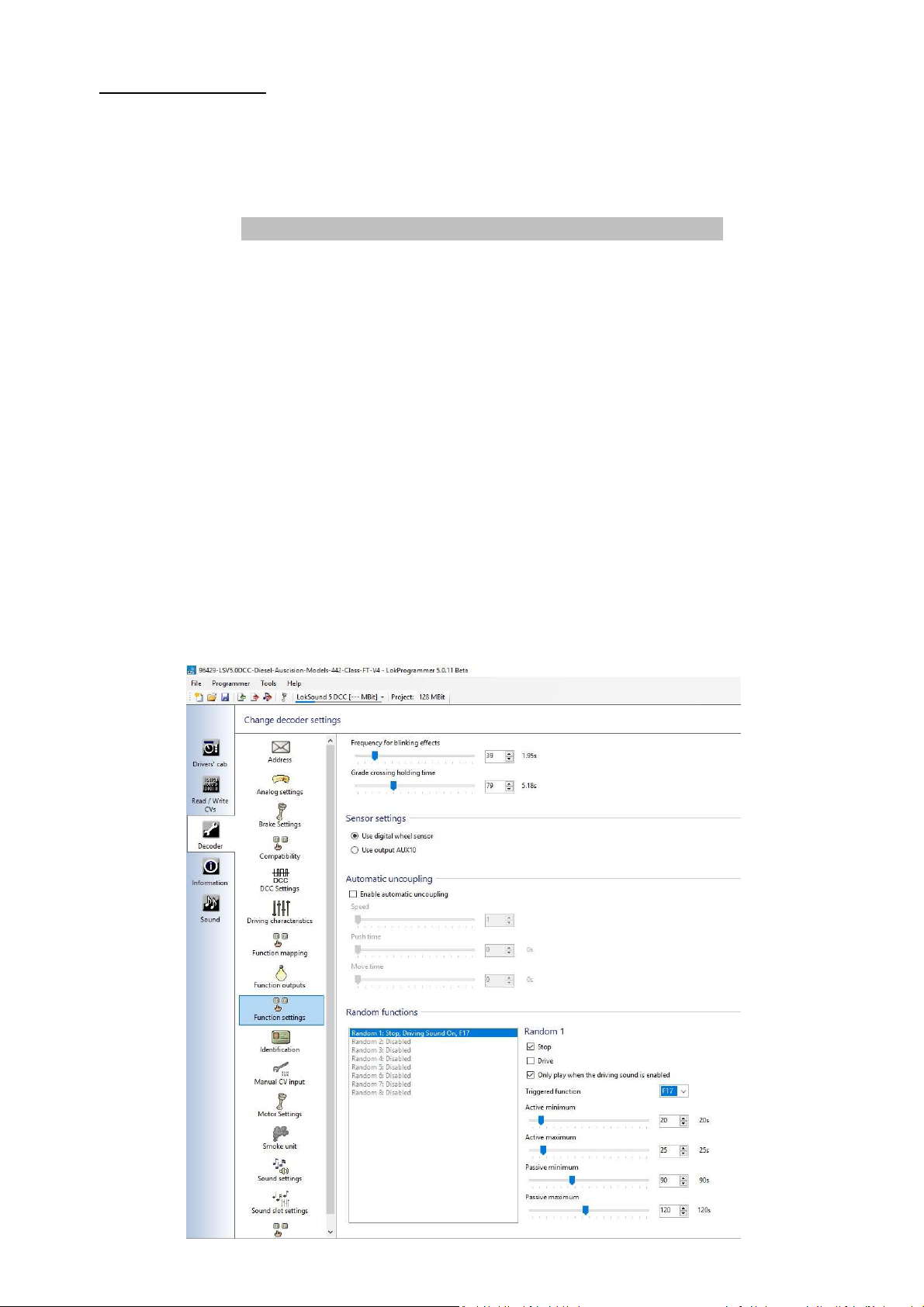
an overview on how to activate and adjust these sounds using Lokprogrammer. With reference to the
below screenshot the following settings can be adjusted to your personal preferences if required. The
random compressor sound will be used as the example, although any sound contained in the default file
can be used. The V5 decoder also has the flexibility of importing further sounds into the models default
file from ESU’s template sound files.
Refer to the 442 class default function table: Compressor being mapped to Function 17.
Under the Decoder – Function Settings – Random functions tab in Lokprogrammer, select position
‘Random 1’ and select triggered function F17, along with the Stop and Only Play When Driving Sound Is
Enabled check box’s. If the ‘Drive’ check box is ticked the random compressor sound will also function
when the locomotive is moving. Active Minimum and Active Maximum is the variable length of time
the random sound will occur, while Passive Minimum and Passive Maximum is the variable time frame
in which the random sound will turn on and function. These values once selected will then require
writing to the decoder in order for them to function.
For further information refer to Chapter 13 ‘Sound Adaptation’ in the Loksound V5 instruction manual.
Lokprogrammer - Decoder – Function Settings - Random Functions
Auscision 442 Class Operating Information (v3) Page 7 of 9
Page 8

Function button 7 (Number 1 End Auxiliary Lighting Logic)
Function button 9 (Number 2 End Auxiliary Lighting Logic)
The lighting for each end of the locomotive has been divided into four separate lighting states. By
pressing the function key repetitively the following applies:
State 1. All Lighting Off.
State 2. Number Boards On. White Marker Lights On. (As in leading end mainline running)
State 3. Number Boards On. Red Marker Lights On. (As in yard shunting. Both ends)
State 4. Red Marker Lights On. (As in the trailing end of a light engine movement)
(State 4 is followed by State 1)
If required, the individual light brightness can be controlled / adjusted separately. Refer to the ESU V5
Decoder Manual, with reference to the auxiliary outputs 1 through 6.
Number 1 end Auxiliary Lighting
Aux 1 - Number Boards, Aux 3 - White Marker Lights, Aux 5 - Red Marker Lights
Number 2 end Auxiliary Lighting
Aux 2 - Number Boards, Aux 4 - White Marker Lights, Aux 6 - Red Marker Lights
PLEASE NOTE:
The following notes are relevant for the previously used Loksound Select Series
Decoder as used in the Auscision 48 class model which had the following
possible issue. The new Loksound V5 decoder utilises an extra 2 sound
processing channels, (now 10 in total) and, following thorough testing, the
problem appears to no longer exist in the V5. However if the issue should
reoccur the following details can be followed in order to remedy the problem.
.........................................................................................................
In order for the Function 7 and Function 9 auxiliary lighting feature to work, ESU
Loksound had to create a lighting logic template. This template is NOT built into the
decoders function logic, however utilises two of the eight available sound processing
flow channels.
Therefore, under certain circumstances and especially when BOTH ends of the model’s
F7/F9 auxiliary lighting are turned on, then some of the secondary sounds may not
function. (For example brake squeal when stopping ) This is due to the non
availability of spare sound channels at that particular moment in time, and is not a
fault with your decoder.
If any activated secondary sound function (including the F7 and F9 lighting) appears
erratic/frozen turn off the locomotive prime mover (F8). This will then allow the
processes selected and queued the available space to function and complete. Once
complete the prime mover (F8) can be turned back on as normal.
If this type of sound response becomes an operating issue, then to free up sound
channels the auxiliary lighting has also been mapped to be individually controlled
with the Logic Functions F21 through to F28. (See function table )
Auscision 442 Class Operating Information (v3) Page 8 of 9
Page 9
Locomotive Horn Sounds
Your 442 class model has been fitted with 2 Brass Castings of the RVB Hurricane 5 chime horn as
originally fitted to the prototype.
For the Loksound V5 decoder the CV for horn selection is 163 with has a default value of 8. The
default horn sound for your model has two slightly different sounding RVB Hurricane 5 Chime horns
at each end of the model depending on the direction of travel. Version 1 of the RVB is on the No.1
end and the Version 2 RVB is on the No.2 end.
At one time or another some individual units within the 442 class fleet have used Nathan Airchime
P5 and M5 horns at various times. These sound files are also available to individualise your model if
required.
To alter the horn sound to the applicable type, refer to the list below and for further reference the
ESU Loksound V5 Decoder Manual.
Please Note: To complete the change in CV value, it is recommended that power to the decoder
be interruption after writing.
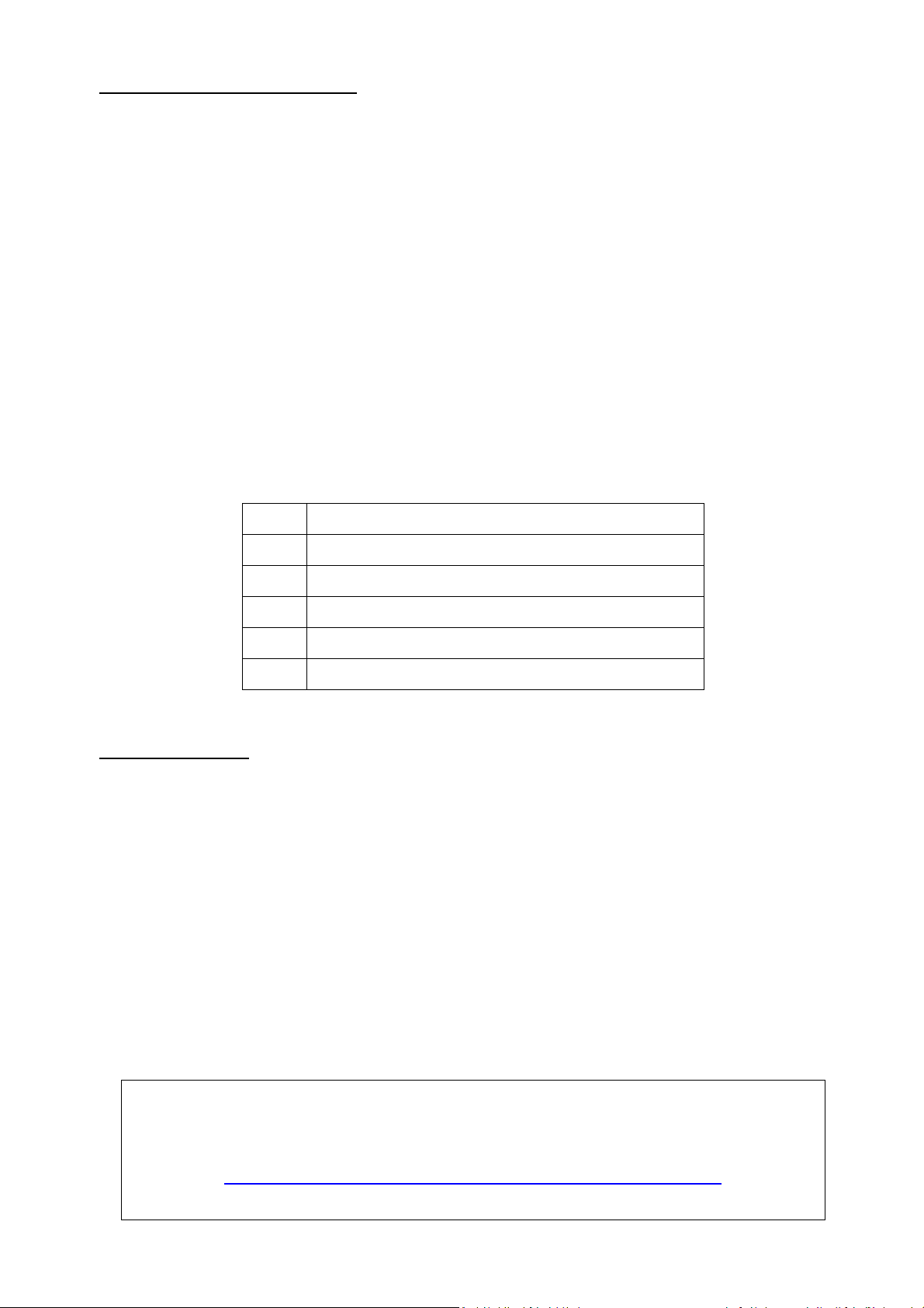
CV163 Horn type
Decoder Reset
If at any point your model’s decoder becomes unresponsive, it may simply require a reset in
order to regain normal function. You can reset the decoder to the current memory default
settings at any time.
In most cases POM (Programming on the Main) will not work to reset a decoder. Please use a
separate programming track.
To reset the decoder:
0
2
7
8
14
Airchime P5
RVB Hurricane 5 Chime (Version 1)
RVB Hurricane 5 Chime (Version 2)
Directional 2 x RVB Hurricane 5 Chime
Airchime M5
• Refer to the ESU V5 Decoder manual for full details.
• Enter the value 8 into CV8.
• To complete the reset, power to the decoder must be interrupted.
For ease of connection to the web links attached within this document, an online version of
the 442 class Operating Information can be found on the Auscision website at the below link:
http://www.auscisionmodels.com.au/442%20Class%20Locomotive.htm
Auscision 442 Class Operating Information (v3) Page 9 of 9
 Loading...