

Aurum Electronics AEC707C User Manual
AEC-707C
DIGITAL WIRELESS TV RECEIVER
Noted the receiver will combine with digital camera fitting to use; Please Read all instructions
before proceeding with the installation
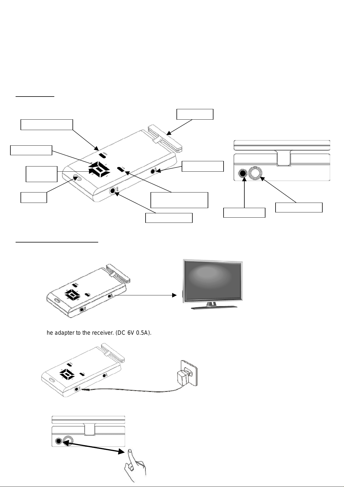
I. OVERVIEW
MENU Button
OK Button
Channel
Button
Buzzer
II. ASSEMBL Y INSTRUCTIONS
View Button (1/4)
(Single/Quad)
Power Socket
Antenna
Video Output
LED indicator
Power switch
1. Connect the receiver to a Monitor/TV with AV cable. (yellow for video and red for audio, but audio is not available
here)
2. Connect the adapter to the receiver. (DC 6V 0.5A).
3. Push the power switch to ON position and the LED indicator lights up
4.Power on the Monitor/TV and select AV mode.
5. Set the channel of the receiver to the same as that of camera fitting by pressing the channel button continuously
and then you can see the camera image displayed on the connected Monitor/TV. This receiver can be paired with up
to four camera fitting.
- Press “MENU Button” then press Channel Button to select “MONITOR” and press “OK button”.
- Press “Channel Button” to select ”Pair Cam” and then press “OK button”.
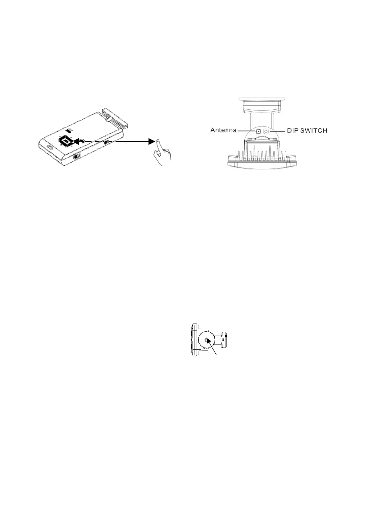
- There is ”1 2 3 4” shown on the TV, to select which number of channel you want to set up this fitting. Within 10 seconds, press
“Channel Button” to select the number of the channel you want then press ”OK button”. Within 10 seconds, press the “Dip
Switch” on the fitting and when you see detecting image displayed on the TV, it means the channel setting is completed. If it
shows “No Connection”, repeat these steps again.
- For other three different fittings, repeat the above same steps to set up the different channel. Press ”View Button” for Quad View
condition to see a split screen view of all channels.
NOTE: 1. To set each channel, TV must be in “Single View”mode.
2. Before setting the channel between the fitting and receiver, first press “Push-Button” switch on the bottom of the fitting,
the stepper motor will stop working (the RED LED will keep flashing) in order to keep “Dip Switch” on the fitting not moving
and can be easily pressed when setting up the channel later.
Push-button
6. Adjust the brightness, contrast and color of the monitor/TV for the perfect ef fect.
III. OPERA TION
When Camera Fitting is in operation, this TV receiver is triggered giving images immediately, the camera operates all the
time whilst the power on.
The unobstructed transmission effective range is about 80 meters, but actual transmission range may vary according
to weather, location, interference and building. One wireless receiver can receive 4 camera images.
To view images from a different channel, press the receiver’s corresponding channel button, and an image will be
displayed on the Monitor/TV.
 Loading...