

Page 1
BEDIENUNGSANLEITUNG
USER INSTRUCTIONS
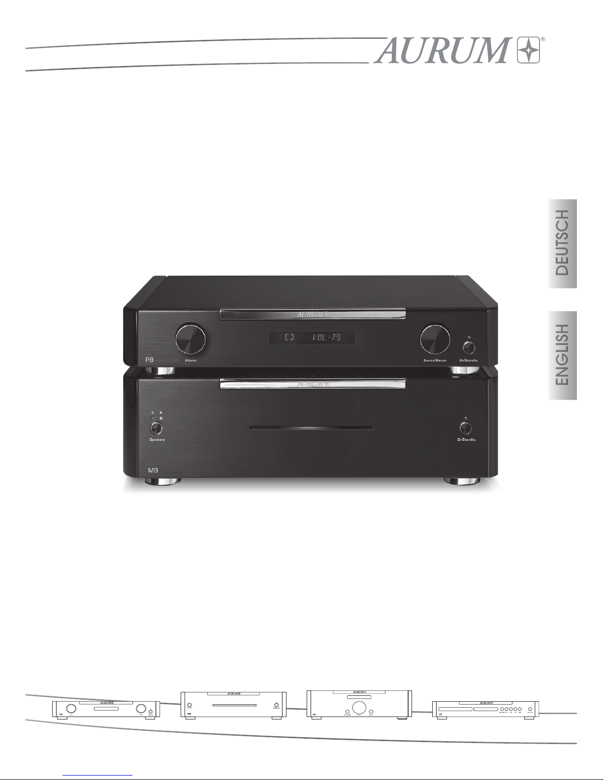
AURUM P8 Vorverstärker
preamplifier
AURUM M8 Endverstärker
amplifier
Page 2
3
DEUTSCH
ENGLISH
Wir gratulieren Ihnen, dass Sie sich für unsere AURUM-Vor- und Endstufen-Kombination
M8/P8 entschieden haben. Es sind Musikliebhaber wie Sie, für deren Ansprüche wir
HiFi-Geräte in einer Güteklasse fertigen, die weit über dem Durchschnitt liegen. Auch
wenn Sie vieles vielleicht schon wissen, führen wir im Folgenden einige Grundregeln
auf, die es Ihnen ermöglichen, Ihre Produkte optimal zu nutzen.
Sicherheitshinweise
Lesen Sie diese Anleitung bitte sorgfältig durch und befolgen Sie alle Schritte,
die für die Inbetriebnahme angegeben sind. Beachten und befolgen Sie
weiterhin alle Warnungen und Sicherheitshinweise, die auf dem Gerät und in der
Bedienungsanleitung angegeben sind. Deponieren Sie diese Anleitung so, dass Sie
bei späteren Fragen schnell zur Hand ist.
• Das Netzkabel und andere Anschlusskabel müssen so verlegt werden, dass
keine Quetschung oder Beschädigung durch Möbel oder durch Trittbelastung
auftreten kann und Stolperfallen vermieden werden.
• Entfernen Sie den Netzstecker bei Gewitter oder bei längerer Nichtverwendung
aus der Steckdose. Das Netzkabel darf aus der Steckdose nur durch ziehen des
Netzsteckers, nicht aber an dem Kabel selbst erfolgen.
• Die Lautsprecheranschlussklemmen des Verstärkers dürfen nur mit den
betreffenden Eingängen der Lautsprecher verbunden werden. Eine irgendwie
geartete Verbindung dieser Klemmen mit dem elektrischen Netz (230V/115V)
ist nicht erlaubt und führt direkt zur sofortigen Zerstörung des Gerätes und
aller angeschlossenen Produkte. Daher muss es vermieden werden, diese
Kabelanschlüsse mit Steckern zu versehen, die auch nur entfernt zu einer
Verwechselung mit Netzsteckern führen könnte.
• An den Lautsprecheranschlussklemmen kann bei hohen Lautstärken, Spannungen von über 30V anliegen. Daher sollten diese nicht während des Betriebes
berührt werden.
Das Blitzsymbol in einem gleich-
schenkligen Dreieck warnt vor
nicht isolierten Komponenten
mit gefährlicher Spannung, die
zu ernsthaften Personenschäden
führen kann.
Das Ausrufungszeichen in einem
gleichschenkligen Dreieck kenn-
zeichnet wichtige Hinweise für
die Nutzung und Wartung Ihres
Gerätes.
Inhalt/Contents/Sommaire/Índice
Sicherheitshinweise 3-4
Bedienelemente auf der P8 Gerätevorderseite 5-6
Anschlüsse auf der P8 Geräterückseite 6-7
Bedienelemente auf der M8 Gerätevorderseite 7-8
Anschlüsse auf der M8 Geräterückseite 8-9
Fernbedienung RC-2 9
Umgebungsbedingungen 10
Inbetriebnahme 11-12
Technische Daten 13-14
Safety instructions 15-16
Control elements on the P8 front panel 17-18
Connections on the P8 rear panel 18-19
Control elements on the M8 front panel 19-20
Connections on the M8 rear panel 20-21
RC 2 Remote Control 21
Ambient conditions 22
Installing 23-24
Technical Data 25-26
Page 3
5
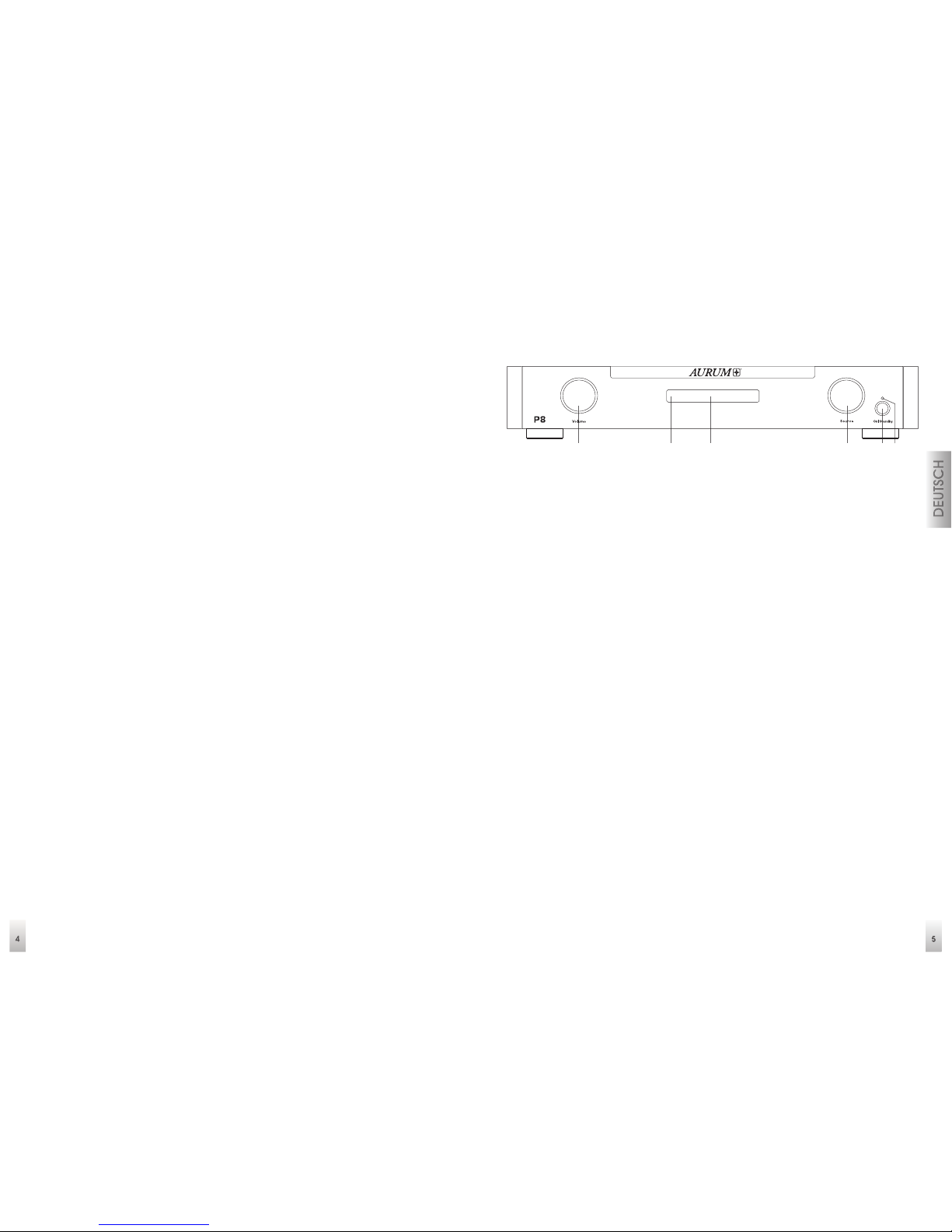
Bedienelemente auf der P8 Gerätevorderseite
1 Lautstärkesteller (Volume):
Mit diesem Drehknopf wird die Lautstärke eingestellt. Die Einstellungen erfolgt in
1dB Schritten und wird im Display angezeigt.
2 Infrarotempfänger: Dieser Sensor empfängt die Infrarotsignale Ihrer Fernbedienung.
Richten Sie die Fernbedienung stets auf diesen Bereich und achten Sie darauf,
dass der Sensor nicht verdeckt wird.
3 Display: Hier werden Statusinformationen angezeigt, die die Handhabung des
Verstärkers vereinfachen.
4 Eingangswahl (Source / Menu): Wählen Sie hier die Quelle durch links oder
rechts drehen des Knopfes. Die aktuelle Quelle wird im Display angezeigt. Durch
Drücken des Knopfes gelangen Sie in die Menüs. (Balance/Bass/Höhen/SIS/HP).
Ein Drehen des Knopfes innerhalb des jeweiligen Menu-Punktes verändert die
Einstellungen.
5 Ein-/Ausschalttaste: Drücken Sie diese Taste um den P8 einzuschalten. Betätigen
Sie diese Taste erneut, um das Gerät wieder auszuschalten (Standby). Im
Standby-Betrieb bleiben alle Einstellungen erhalten.
6 Betriebsanzeige: Diese Anzeige leuchtet blau, wenn sich das Gerät im Standby-
Modus befindet und signalisiert damit, dass Sie das Gerät jederzeit mit der
Fernbedienung Taste (2) einschalten können.
Hinweise:
Bei der SIS-Funktion handelt es sich um eine automatisierte Abschaltung des
Gerätes nach ca. 15 Minuten falls kein Signal am Eingang des Gerätes mehr
anliegt. (Auslieferzustand = AUS) Falls die SIS-Funktion am Vorverstärker P8
aktiviert wird und eine LINK-Verbindung zur M8 besteht, erfolgt hier ebenfalls die
Abschaltung des Endverstärker M8.
• Verwenden Sie das Gerät niemals in der Nähe von Wasser, in Feuchträumen oder
im Freien. Wie bei allen nicht speziell hierfür konstruierten Geräten, kann Nässe
die elektrische Isolierung überbrücken und somit ein lebensgefährliches Risiko
darstellen.
• Schützen Sie dieses Gerät vor Spritzwasser. Achten Sie bitte darauf, dass keine
Gefäße, die Flüssigkeiten enthalten (z.B. Vasen), auf dem Gerät abgestellt
werden.
• Stellen Sie das Produkt nicht in der Nähe von Wärmequellen wie Heizstrahler,
Heizkörper, Öfen oder anderen Geräten auf.
• Schlitze und Öffnungen im Gehäuse dienen der Entlüftung und sorgen für
zuverlässigen Betrieb. Daher dürfen sie nicht verstellt oder abgedeckt werden.
• Bei einer massiven Überlastung der Geräte durch sehr große Lautstärken ist
das Durchbrennen einzelner Bauelemente trotz Sicherungseinrichtungen nicht
vollständig auszuschließen. In der Theorie könnte sogar ein Brand innerhalb eines
Gerätes in einem derartigen Überlastungsfall entstehen. Daher sollten Verstärker
die in diesem Grenzbereich betrieben werden, nicht unbeaufsichtigt bleiben.
• Die Wartung Ihres Gerätes überlassen Sie bitte ausschließlich dem technischen
Service. Wartung wird notwendig, bei jeglicher Art von Schäden, d.h. bei
beschädigten Netzkabeln und Steckern, oder nach dem Herabfallen von
Gegenständen auf das Gerät, sowie dem Sturz des Gerätes selbst oder nach
dem Eindringen von Flüssigkeiten. Öffnen Sie das Gerät nie selbst, da jeder
Umgang mit der Netzspannung (230V/115V) lebensgefährlich ist.
• Verwenden Sie bitte ausschließlich Möbel und andere Geräte zum Anbringen
und Draufstellen der Produkte, die beim Hersteller erhältlich sind oder von Ihm
empfohlen werden. Beachten Sie bitte, dass fahrbare Tischgeräte oder Regale,
auf denen die Produkte platziert werden, sehr vorsichtig zu bewegen sind, um
Schäden oder Verletzungen durch ein umkippen zu vermeiden.
• Sehr große Lautstärken im Dauerbetrieb können für den Anwender zu gesundheitsschädlichen Auswirkungen führen!
• Verwenden Sie zur Reinigung Ihrer Geräte nur ein trockenes und weiches Tuch.
• Bitte heben Sie die Verpackung für einen eventuell späteren Transport auf, und
halten Sie die Polybeutel von Kindern fern, da hier bei unsachgemäßen Umgang
ein Erstickungsrisiko besteht.
41 5 62 3
Page 4
6
Bei bestehender LINK -Verbindung zwischen P8 und M8 wird bei der Betätigung
der Taste (5) am Vorverstärker auch die Ein- oder Ausschaltung des Endverstärkers
M8 mit übernommen.
Unter dem Menu Punkt (HP) wird der auf der Geräterückseite befindlichen
Kopfhörerausgang an- oder ausgeschaltet.
Bei aktivierten Kopfhörerausgang wird der Signalweg zu den Vorverstärker-
ausgängen unterbrochen!
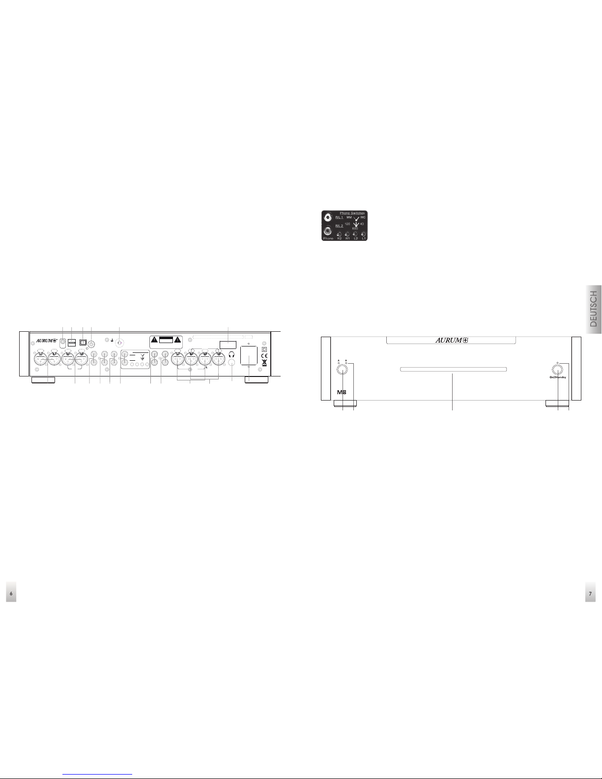
Anschlüsse auf der P8 Geräterückseite
1 XLR 2 symmetrische Eingänge
2 XLR 1 symmetrische Eingänge
3 AUX Eingänge für analoge Tonsignale
4 Tuner analoge Eingängr für Ihr Radio
5 CD analoge Eingänge für CD-Spieler
6 Phono MM und MC Eingang
7 Direct Bypass diese Eingänge umgehen die Klang- und Lautstärkeeinstellung
und sind für den Betrieb in Heimkino-Anlagen gedacht
8 OUT 3 unsymmetrische Ausgänge
9 OUT 2 symmetrische Ausgänge
10 OUT 1 symmetrische Ausgänge
11 Kopfhörer Stereo-Klinkenbuchse
12 Netzanschlussbuchse
13 Netzschalter trennt das Gerät komplett von der Netzversorgung
14 Ground Phono Masseanschluss
15 SPDIF koaxialer Digital-Eingang
16 TosLink optischer Digital-Eingang
17 USB Digital-Eingang für den PC-Anschluss
18 Link Out 12 V Steuerausgang zur Endstufe
Hinweis: PHONO
Um die Signalwege für Phono MM (Moving Magnet) und MC
(Moving Coil) so optimal wie möglich zu gestalten, erfolgt die
Umschaltung der Betriebsarten auf der Geräterückseite einzeln
pro Kanal!
Die Schalter L1 und R1 ermöglichen die Auswahl zwischen dem MM (Schalterstellung
-Links) und dem MC – Betrieb. (Schalterstellung -Rechts)
Die mehrstufigen Schalter L2 und R2 bieten in der Betriebsart MC die Möglichkeit
der Impedanz-Anpassung für verschiedene MC-Systeme. (Links = 120 Ohm, Mitte =
600 Ohm und Rechts = 40 Ohm)
Bedienelemente auf der M8 Gerätevorderseite
1 Speaker: Taste zur Lautsprecher-Umschaltung
(Reihenfolge: Gruppe A / B / A+B / AUS
2 LED: Lautsprecher-Gruppenanzeige
3 Betriebsanzeige: diese Anzeige leuchtet blau, wenn das Gerät eingeschaltet
und im Betrieb ist
4 Ein-/Ausschalttaste: Drücken Sie diese Taste um den M8 einzuschalten. Betätigen
Sie diese Taste erneut, um das Gerät wieder auszuschalten (Standby). Im
Standby-Betrieb bleiben alle Einstellungen erhalten.
5 Standby-Anzeige: Diese Anzeige leuchtet blau, wenn sich das Gerät im Standby-
Modus befindet und signalisiert damit, dass Sie das Gerät jederzeit mit der
Fernbedienung oder mit der Taste (4) wieder eingeschaltet werden kann.
Fuse:
100V/115V: T250 mA L250V
230V: T125 mA L250V
~50/60 Hz
max. Power Cons.: 10W
quadra l G mbH & Co. KG - Am Herren häu ser B ahnh of 26-28 - D- 30419 Hannover
On
Off
Out 2
L
R
Out 1
LR
Out 3
RLRLR
L
R
L
Aux
Tuner
CD Phono L2 L1R2 R1
Direct
Bypass
40
600
120
R/L 2
MCMMR/L 1
Phono Sw itches
XLR 2
LR
XLR 1
LR
Phono
GND
USB
TosLink
SPDIf
Digital In
Link
Out
Handmade in Germany
W ARNI N G :
TO REDUCE THE RISK
OF ELECTRICAL SHOCK
OR FIRE, DO NOT EXPOSE
THIS APPLIANCE TO
MOISTURE OR RAIN.
DO NOT REMOVE C OVER. NO USER
SERVICEABLE PARTS INSIDE. REFER
SERVICING TO QUALIFIED PERSON NEL.
CAUTION
RISK OF ELECTRIC SHOCK
DO NOT OPEN
1 2 3 4 5 6 7 8 9 10 11 12
131415161718
1 432 5
Page 5
8
Hinweise:
Sollte diese Anzeige blinken, haben die Schutzschaltungen des Gerätes die
Lautsprecher im Fehler- oder Überlastungsfall abgeschaltet. Das Gerät kann nur
durch eine erneute Betätigung des Netzschalters (9) auf der Geräterückseite
zurückgesetzt werden.
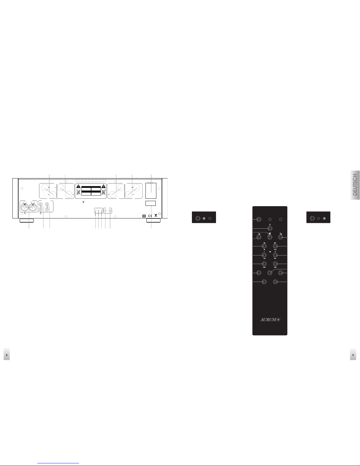
Anschlüsse auf der M8 Geräterückseite
1 Balanced In symmetrische XLR-Eingänge
2 Unbalanced In RCA Stereo-Eingänge
3 RCA Stereo-Eingänge, die auch als Ausgänge zur Weiterleitung der
Eingangssignale (2) genutzt werden können
4 RCA/XLR Betriebsartenumschalter für die Eingänge 1-3
5 Mono/Stereo Betriebsartenumschalter. Bitte Hinweis zu Inbetriebnahme
beachten
6 Gain mehrstufiger Schalter zur Anpassung der
Eingangsempfindlichkeit (-3dB / 0dB / -10dB)
7 Link In Eingang für den 12V Steueranschluss von der Vorstufe P8
8 Link Out Ausgang zur Weiterführung der Steuerspannung für andere
Geräte
9 Netzschalter trennt das Gerät komplett von der Netzversorgung
10 Netzanschlussbuchse
11 Lautsprecherausgang A linker Kanal
12 Lautsprecherausgang B linker Kanal
13 Lautsprecherausgang B rechter Kanal
14 Lautsprecherausgang A rechter Kanal
Hinweise:
Wenn die Schalter 4, 5 und 6 betätigt werden, erfolgt eine Pause von ca. 5
Sekunden bis alle Arbeitspunkte stabilisiert sind und eine Signalfreigabe erfolgen
kann.
Fernbedienung RC 2 (OPTIONAL)
Mit der System-Fernbedienung RC-2 können die AURUM-Verstärker P8 / M8 / A5 / A3
und die AURUM CD-Player C3 / C5 / C5 DA individuell angesteuert werden.
Wichtiger Hinweis:
Um die Funktionen eines Verstärkers oder CD-Spielers fernsteuern zu können,
muss die entsprechende Betriebsart vorher mit der Anwahl-Taste (SELECT)
gewählt werden.
Verstärkerbetrieb
1 SELECT-Taste
2 ON/OFF-Taste
3 Stummschaltung
(MUTE)
4 Lautstärke Minus
5 Lautstärke Plus
6 Balance Links
7 Balance Rechts
8 Signalquelle
Abwärts
9 Signalquelle
Aufwärts
14 Pegeleinsteller (für
jeden Eingang mit
Taste 4+5)
15 Display-Helligkeit
CD-Betrieb
1 SELECT-Taste
2 ON/OFF-Taste
3 Stummschaltung
(MUTE)
4 ohne Funktion
5 ohne Funktion
6 Stopp
7 Wiedergabe/
Pause
8 Suchlauf Rückwärts
9 Suchlauf Vorwärts
10 Titelsprung
Rückwärts
11 Titelsprung
Vorwärts
12 Wiederholung
(Titel/Alle)
13 Zufallswiedergabe
15 Display-Helligkeit
16 ohne Funktion (nur
C5 DA externer
D/A-Wandler)
Repeat
RL
Select
AMP
CD
Prog.
Opt.
Random
Display
Select
AMP
CD
Select
AMP
CD
1
2
3
4
6
8
10
12
15
5
7
9
11
13
14
16
On
Off
max. Power Consumption: 1,
2kW
Fuse:
100V / 115V: T6.3, A L250V
230V:
T3.15, A L250V
CAUTION
RISK OF ELECTRIC SHOCK
DO NOT OPEN
ACHTUNG
STROMSCHLAG GEFAHR
NICHT ÖFFNEN
ATTENTION
RISQUE DE CHOC ELECTRIQUE
NE PAS OUVRIR
ATENCIÓN
RIESGO DE DESCARGA ELCTRICA
NO ABRIR
DO NOT REMOVE C OVER. NO USER-SERVICEABLE PAR TS
INSIDE. REFER SERVICING TO QUALIFIED PERSONNEL.
TO REDUCE THE RISK OF ELECTRICAL SHOCK OR FIRE, DO NOT
EXPOSE THIS APPLIANCE TO MOISTURE OR RAIN.
In Out
Link
Gain
Mono / Stereo
RCA / XLR
+3 / 0
/
-10 dB
quadral GmbH & Co. KG - A m Herrenhäuser B ahnhof 26-28 - D-3041 9 Hannover
Handmade in Germany
®
AURUM
Balanced In
Right
Left
Mono In
Unbalanced In
Right
Left
Mono In
A
B
Right
+ +
Mono
AB
Left
+ +
Mono+
1 2 3 4 5 76 8 9
101112 1314
RC-II
Page 6
10
Umgebungsbedingungen
Die Fernsteuerung hat eine Reichweite von bis zu 6 m und funktioniert einwandfrei
in einem Einstrahlwinkel von bis zu 30° bezogen auf die Gerätevorderseite. Staub
am Sender oder Schmutz vor dem Empfangssensor und der Betrieb in der Nähe
von Leuchtstoffröhren kann die Reichweite verringern. Eine direkte Sichtverbindung
zwischen Sender und Empfänger ist erforderlich.
Hinweise zum Ausbau und zur umweltgerechten Entsorgung verbrauchter Batterien
Das abgebildete Symbol kann auf dem Gehäuse eines Produkts, dessen
Verpackung sowie in den Unterlagen oder der Bedienungsanleitung
auftreten. Es zeigt an, dass sowohl das Produkt selbst, als auch die
mitgelieferten oder im Produkt verbauten Batterien niemals in den
Hausmüll gelangen dürfen. Sie müssen umweltgerecht (entsprechend
lokaler Richtlinien oder gemäß der Europäischen Richtlinien 2002/96/EC und
2006/66/EC) entsorgt werden.
Bitte informieren Sie sich, wo in Ihrer Nähe die nächste Abgabestelle für Elektronikschrott oder ein Recycling-Hof ist.
Der korrekte Umgang mit dem Produkt und den Batterien hilft Recourcen zu
schonen und beugt körperlichen und Umweltschäden vor. Die in der Fernbedienung
mitgelieferte Batterie (CR2032) enthält Lithium und muss, wie oben beschrieben,
umweltgerecht entsorgt werden.
Folgen Sie den nachstehenden Hinweisen, um die Batterie in der Fernbedienung zu
erneuern oder auch zu entfernen.
1. Entfernen Sie die Schrauben auf der Fernbedienungsunterseite und heben Sie
den Deckel ab.
2. Entfernen Sie die Batterie durch einfaches schieben aus ihrer Halterung.
3. Achten Sie bei dem Erneuern der Batterie auf die Polarität! Die mit einem (+)
Pluszeichen versehene Seite der Batterie muss nach oben zu der ebenfalls mit (+)
gekennzeichneten Halterung weisen.
4. Setzen Sie den Gehäusedeckel wieder auf und befestigen ihn mit den Schrauben.
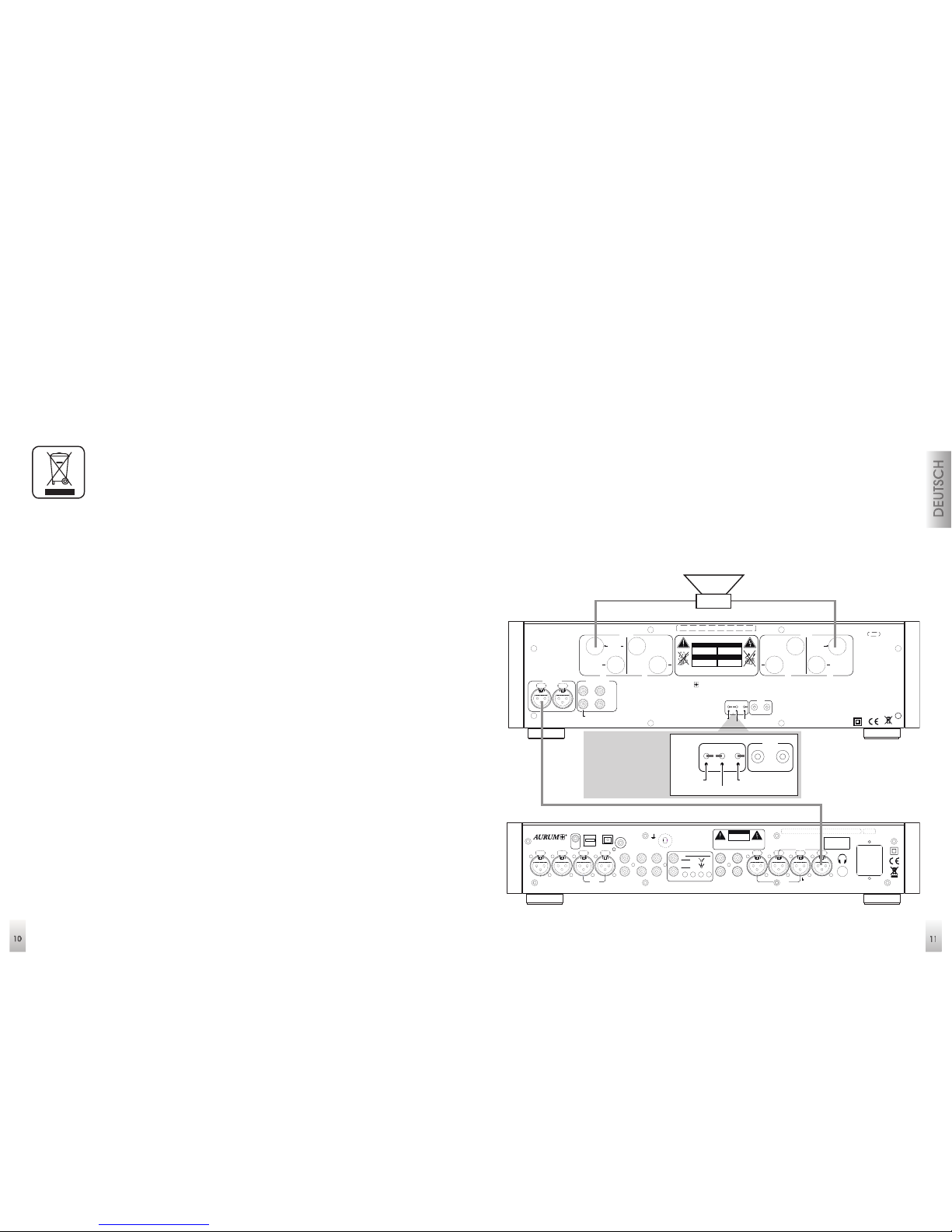
Inbetriebnahme
1. Stellen Sie sicher, dass die Geräte ausgeschaltet sind.
2. Schließen Sie die Geräte mit den beiliegenden Netzkabeln am Stromnetz an.
3. Verbinden Sie die Gerätausgänge des Vorverstärkers P8 mit den Eingängen der
Endstufe M8 (optimalerweise verwenden Sie hierfür eine XLR - Kabelverbindung)
(Kontaktbelegung des XLR- Anschlusses: Pin 1= Masse; Pin 2 = Plus/Signal; Pin 3 =
Minus)
4. Schließen Sie nun die Ihnen zur Verfügung stehenden Zuspielgeräte an. (Tuner,
CD-Spieler, PC etc. an.)
5. Verbinden Sie falls gewünscht, die Link-out Buchse der P8 mit der Link-in Buchse
der M8.
6. Der Anschluss der Lautsprecher erfolgt an den rückseitigen Schraubklemmen je
nach der gewünschten Betriebsart in Mono oder Stereo.
7. Achten Sie bitte darauf, dass jeweils der Plus und Minus Anschluss am Verstärker
auch mit dem Plus und Minus Anschluss an den Lautsprechern verbunden ist, um
Verpolungen zu vermeiden.
Mono Anschluss
(linker Kanal)
On
Off
max. Power Consumption: 1,
2kW
Fuse:
100V / 115V: T6.3, A L250V
230V:
T3.15, A L250V
CAUTION
RISK OF ELECTRIC SHOCK
DO NOT OPEN
ACHTUNG
STROMSCHLAG GEFAHR
NICHT ÖFFNEN
ATTENTION
RISQUE DE CHOC ELECTRIQUE
NE PAS OUVRIR
ATENCIÓN
RIESGO DE DESCARGA ELCTRICA
NO ABRIR
DO NOT REMOVE C OVER. NO USER-SERVICEABLE PAR TS
INSIDE. REFER SERVICING TO QUALIFIED PERSONNEL.
TO REDUCE THE RISK OF ELECTRICAL SHOCK OR FIRE, DO NOT
EXPOSE THIS APPLIANCE TO MOISTURE OR RAIN.
In Out
Link
Gain
Mono / Stereo
RCA / XLR
+3 / 0
/
-10 dB
quadral GmbH & Co. KG - A m Herrenhäuser B ahnhof 26-28 - D-3041 9 Hannover
Handmade in Germany
®
AURUM
Balanced In
Right
Left
Mono In
Unbalanced In
Right
Left
Mono In
A
B
Right
+ +
Mono
AB
Left
+ +
Mono+
Fuse:
100V/115V: T250 mA L250V
230V: T125 mA L250V
~50/60 Hz
max. Power Cons.: 10W
quadra l G mbH & Co. KG - Am Herren häu ser B ahnh of 26-28 - D- 30419 Hannover
On
Off
Out 2
L
R
Out 1
LR
Out 3
RLRLR
L
R
L
Aux
Tuner
CD Phono L2 L1R2 R1
Direct
Bypass
40
600
120
R/L 2
MCMMR/L 1
Phono Sw itches
XLR 2
LR
XLR 1
LR
Phono
GND
USB
TosLink
SPDIf
Digital In
Link
Out
Handmade in Germany
W ARNI N G :
TO REDUCE THE RISK
OF ELECTRICAL SHOCK
OR FIRE, DO NOT EXPOSE
THIS APPLIANCE TO
MOISTURE OR RAIN.
DO NOT REMOVE C OVER. NO USER
SERVICEABLE PARTS INSIDE. REFER
SERVICING TO QUALIFIED PERSON NEL.
CAUTION
RISK OF ELECTRIC SHOCK
DO NOT OPEN
– +
Schalterposition XLR
und Mono bei - 10dB
XLR linker Kanal
On
Off
max. Power Consumption: 1,
2kW
Fuse:
100V / 115V: T6.3, A L250V
230V:
T3.15, A L 250V
ACHTUNG
STROMSCHLAG GEFAHR
NICHT ÖFFNEN
ATENCIÓN
RIESGO DE DESCARGA ELCTRICA
NO ABRIR
-
SERVICEA BLE PARTS
In Out
Link
Gain
Mono / Stereo
RCA / XLR
+3 / 0
/
-10 dB
AB
Left
+ +
Mono+
Page 7
13
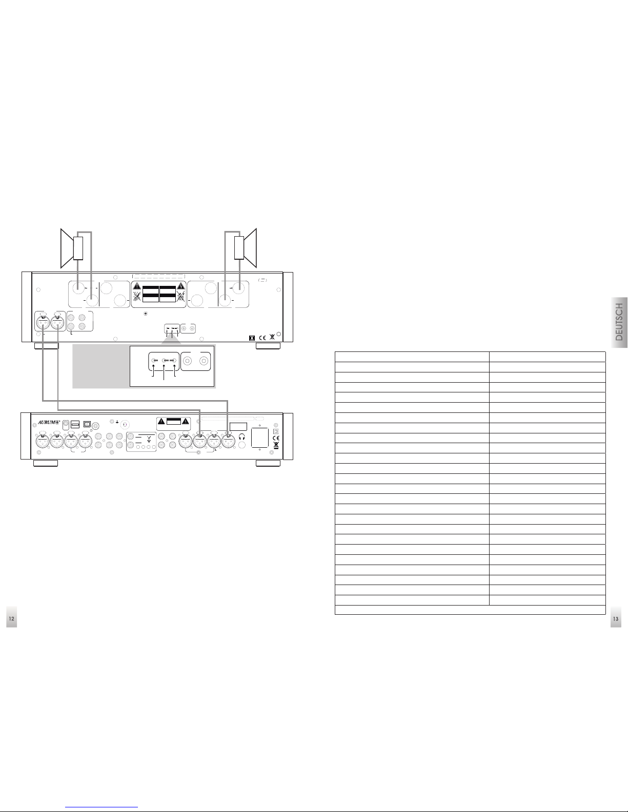
Stereo Anschluss
(Lautsprecher A)
8. Schalten Sie Ihre Geräte M8 und P8 nun mit den Netzschaltern ein.
9. M8 Netzschalter (9) und P8 Netzschalter (13) auf der Geräterückseite in die
ON-Position. Die Standby LED auf den Fronten leuchten.
10. Betätigen Sie nun die On/Standby Taste (5) auf der Gerätefront des Vorverstärkers
P8 oder die Taste (2) auf der Fernbedienung, um Ihr Geräte in Betrieb zu
nehmen. Die Einschaltung der M8 erfolgt gemeinsam über die P8, wenn die LINK
-Verbindung vorgenommen wurde.
11. Falls die LINK-Verbindung nicht besteht, müssen Sie die Taste (4) auf der M8
Gerätefront zusätzlich betätigen.
Hinweis:
Ihre P8 / M8 verfügen über eine besonders stromsparende Standby-Schaltung,
daher kann die An-Ausschaltung im normalen Betrieb stets über die On/Standby
Taste am Gerät oder mit der Fernbedienung RC-2 erfolgen.
Mit der Fernbedienung RC-2 stehen Ihnen erweiterte
Komforteinstellungen zur Verfügung.
Stummschaltung / Mute (Taste 3)
Balance Einstellung (Tasten 6 + 7)
Mehrstufige Anpassung der Displayhelligkeit (Taste 15 / Nur bei P8, A5, A3)
Eingangspegeleinstellung für alle Eingänge (Taste 14)
Beispiel: Eingangspegeleinstellung
Signalquelle mit den Tasten 8 (-) oder 9 (+) anwählen, dann Taste 14 (Prog.) betätigen
und mit den Volume - Tasten (4 +5) die gewünschte Eingangslautstärke einstellen.
Zum Speichern Taste 14 (Prog.) erneut drücken.
Technische Daten M8
Eingangsempfindlichkeit für 1W an 4 Ohm -26 dBV
Eingangsimpedanz 47 kOhm
Spannungsverstärkung 22/32/35 dB
Maximale Eingangsspannung 6 V
Max. Spannung am Lautsprecherausgang (Stereo) 50 V
Max. Spannung am Lautsprecherausgang (Mono) 70 V
Minimale Lautsprecherimpedanz (Stereo) 2 Ohm
Minimale Lautsprecherimpedanz (Mono) 2 Ohm
Stereo-Ausgangleistung an 8 Ohm 120 W
Stereo-Ausgangleistung an 4 Ohm 200 W
Mono-Ausgangsleistung an 8 Ohm 240 W
Mono-Ausgangsleistung an 4 Ohm 350 W
Frequenzgang 1Hz-110kHz(-3dB)
Harmonische Verzerrungen <0.03%
Geräuschspannungsabstand A-bewertet 85 dB
Netzanschluss 115V/230V umschaltbar
Leistungsaufnahme (Normalbetrieb) 25 W
Leistungsaufnahme (Vollaussteuerung) max. 1200 W
Leistungsaufnahme (Standby) <0,5W
Eingänge 2 Paar RCA, 1 Paar XLR
Lautsprecherausgänge 2 Paar
12V Link Anschluss In+Out (Kurzschlußfest) 3,5mm Mono Miniklinke
Schutzschaltungen Temperatur, Über last
Abmessungen (B x H x T) 453 x 130 x 330 mm
Gewicht 13,79kg
* Breite mit Holzseitenteilen, Höhe mit Füssen, Tiefe mit Lautsprecherklemmen
Schalterposition
XLR und Stereo
On
Off
max. Power Consumption: 1,
2kW
Fuse:
100V / 115V: T6.3, A L250V
230V:
T3.15, A L 250V
ACHTUNG
STROMSCHLAG GEFAHR
NICHT ÖFFNEN
ATENCIÓN
RIESGO DE DESCARGA ELCTRICA
NO ABRIR
-
SERVICEA BLE PARTS
In Out
Link
Gain
Mono / Stereo
RCA / XLR
+3 / 0
/
-10 dB
AB
Left
+ +
Mono+
Fuse:
100V/115V: T250 mA L250V
230V: T125 mA L250V
~50/60 Hz
max. Power Cons.: 10W
quadra l G mbH & Co. KG - Am Herren häu ser B ahnh of 26-28 - D- 30419 Hannover
On
Off
Out 2
L
R
Out 1
LR
Out 3
RLRLR
L
R
L
Aux
Tuner
CD Phono L2 L1R2 R1
Direct
Bypass
40
600
120
R/L 2
MCMMR/L 1
Phono Sw itches
XLR 2
LR
XLR 1
LR
Phono
GND
USB
TosLink
SPDIf
Digital In
Link
Out
Handmade in Germany
W ARNI N G :
TO REDUCE THE RISK
OF ELECTRICAL SHOCK
OR FIRE, DO NOT EXPOSE
THIS APPLIANCE TO
MOISTURE OR RAIN.
DO NOT REMOVE C OVER. NO USER
SERVICEABLE PARTS INSIDE. REFER
SERVICING TO QUALIFIED PERSON NEL.
CAUTION
RISK OF ELECTRIC SHOCK
DO NOT OPEN
On
Off
max. Power Consumption: 1,
2kW
Fuse:
100V / 115V: T6.3, A L250V
230V:
T3.15, A L250V
CAUTION
RISK OF ELECTRIC SHOCK
DO NOT OPEN
ACHTUNG
STROMSCHLAG GEFAHR
NICHT ÖFFNEN
ATTENTION
RISQUE DE CHOC ELECTRIQUE
NE PAS OUVRIR
ATENCIÓN
RIESGO DE DESCARGA ELCTRICA
NO ABRIR
DO NOT REMOVE C OVER. NO USER-SERVICEABLE PAR TS
INSIDE. REFER SERVICING TO QUALIFIED PERSONNEL.
TO REDUCE THE RISK OF ELECTRICAL SHOCK OR FIRE, DO NOT
EXPOSE THIS APPLIANCE TO MOISTURE OR RAIN.
In Out
Link
Gain
Mono / Stereo
RCA / XLR
+3 / 0
/
-10 dB
quadral GmbH & Co. KG - A m Herrenhäuser B ahnhof 26-28 - D-3041 9 Hannover
Handmade in Germany
®
AURUM
Balanced In
Right
Left
Mono In
Unbalanced In
Right
Left
Mono In
A
B
Right
+ +
Mono
AB
Left
+ +
Mono+
– +
– +
XLR Stereo-Verbindung
Page 8
15
Technische Daten P8
Eingangsimpedanz (XLR) 47 kOhm
Eingangsempfindlichkeit (XLR) 100mV
Geräuschspannungsabstand (XLR) A-bewertet 94 dB
Eingangsimpedanz (Line) 47 kOhm
Eingangsempfindlichkeit (Line) 100mV
Geräuschspannungsabstand (Line) A-bewertet 94 dB
Eingangsimpedanz Phono MM 47 kOhm
Eingangsempfindlichkeit Phono MM 2,6mV
Geräuschspannungsabstand (Phono MM) A-bewertet 90 dB
Eingangsimpedanz Phono MC 40 / 120 / 600 Ohm
Eingangsempfindlichkeit Phono MC 0,26mV
Geräuschspannungsabstand (Phono MC) A-bewertet 74 dB
Spannungsverstärkung (Line) 45 dB
Maximale Eingangsspannung (Line) 6V
Max. Spannung am XLR-Ausgang 15V
Ausgangsimpedanz (XLR) 300 Ohm
Max. Spannung am RCA-Ausgang 8 V
Ausgangsimpedanz (RCA) 600 Ohm
Regelbereich Volume 99 dB
Regelbereich Balance, Bass, Höhen +/-6dB
Regelbereich Vorpegel -6dB
Regelgenauigkeit 0.1dB
Kanalgleichheit besser 0,05dB
Frequenzgang 1Hz-110kHz (-3dB)
Harmonische Verzerrungen <0.03%
Kopfhörerausgang Stereo 6,3mm / 600 Ohm
12V Link Anschluss (Kurzschlussfest) 3,5mm Mono Miniklinke
SIS (Auto On/off) nach 15 Min. ohne Signal
Netzanschluss 115V/230V umschaltbar
Leistungsaufnahme (Normalbetrieb) 10 W
Leistungsaufnahme (Standby) <0,5W
Analog Eingänge 4 Paar RCA, 2 Paar XLR, 1 Paar Phono
Digital Eingänge (24bit / 192KHz) 1 x Optisch / 1x Koaxial
USB 1 x USB / Typ B (48KHz)
Ausgänge 2 Paar XLR, 1 Paar RCA
Abmessungen (B x H x T) 453 x 82 x 330 mm*
Gewicht 5,31kg
* Breite mit Holzseitenteilen, Höhe mit Füssen, Tiefe mit Lautsprecherklemmen
First of all, we would like to thank you for choosing our AURUM M8 / P8 pre-amplifier combination. We manufacture top-quality HiFi equipment which we hope will
delight you each time you use it. Our goal in all of this is to truly satisfy the requirements of music lovers just like you.
Even though you may already be knowledgable in using this type of equipment,
we’d still like to introduce some basic rules and guidance that will enable you to
get the best out of your purchase. Please do take a few moments to read this information.
Safety instructions
Please read through these instructions carefully and follow all of the steps listed here
for installing the equipment. You must abide by all of the warnings and safety instructions that are stipulated on the unit and in this instruction manual. Keep this manual
close to hand so that you can consult it if you have any questions later on.
• The mains power cable and other connecting cables must be laid so that none
of them are crushed or damaged by furniture, are being trodden on, and / or
that nobody will trip over them.
• Take the power plug out of the socket during lightening storms or if the equipment will not be used for a long time. Always pull the plug out of the socket and
never remove it by pulling on the cable!
• The amplifier‘s speaker terminals must only be connected up to the relevant
inputs on the speakers. You must never connect these terminals up to the electrical mains supply (230V / 115V) as this will destroy the equipment and all interconnected units immediately. Therefore you must never fit plugs on these cable
connections to ensure that they can never be mixed up with mains plugs.
• Voltages above 30V can be present at the speaker terminals if high volume is
being used. Therefore you should never touch the terminals when the amplifier is
being used.
The lightening symbol inside an
equal-sided triangle is used to
warn you about the presence
of non-insulated components
carrying a dangerous, live
voltage that might cause severe
personal injuries.
The exclamation mark inside an
equal-sided triangle indicates
that there is important information
available regarding the use and
maintenance of your equipment.
Page 9
16
• Never use the equipment in the vicinity of water, in humid areas or outdoors. Moisture can bypass the electrical insulation and this will create a life-threatening risk
as is the case with all equipment that has not been specially designed against
the penetration of moisture.
• Protect the equipment against water being sprayed on it. You must also ensure
that no vessels containing liquid (e.g. vases) are placed on top of the equipment.
• Do not place the equipment in the vicinity of a heat source such as an electric
fire, radiator, oven or similar.
• The slits and openings in the enclosure provide the ventilation and ensure reliable
operation. They must never be misaligned or covered.
• Burning-out of specific components cannot be completely excluded, despite the
use of protective devices, if the equipment is severely overloaded by continually
using very loud sound levels. A fire might also be caused inside the equipment in
theory, as a result of this type of overloading. Therefore the amplifier should always
be used within its limits and it should not be left unattended.
• Only our technical service should undertake the maintenance of your equipment. Maintenance will be necessary if any type of damage occurs, i.e. if the
power cables or plugs are damaged, if an object falls on the equipment, if the
equipment is dropped or if liquid seeps into it. Never open the equipment as you
might touch the mains voltage (230V / 115V), which is dangerous.
• Only use furniture and other units for attaching and putting the equipment on
that can be obtained from or are recommended by the manufacturer. You must
ensure that moveable tabletop units or shelves on which the equipment will be
placed are always moved very carefully in order to prevent damage or injuries
from being caused if the equipment tips over.
• Continuously loud volume can damage your hearing!
• Only use a dry, soft cloth to clean your equipment.
• Keep the packing for possible transportation use later on and keep the plastic
bag well away from children, due to the risk of asphyxiation.
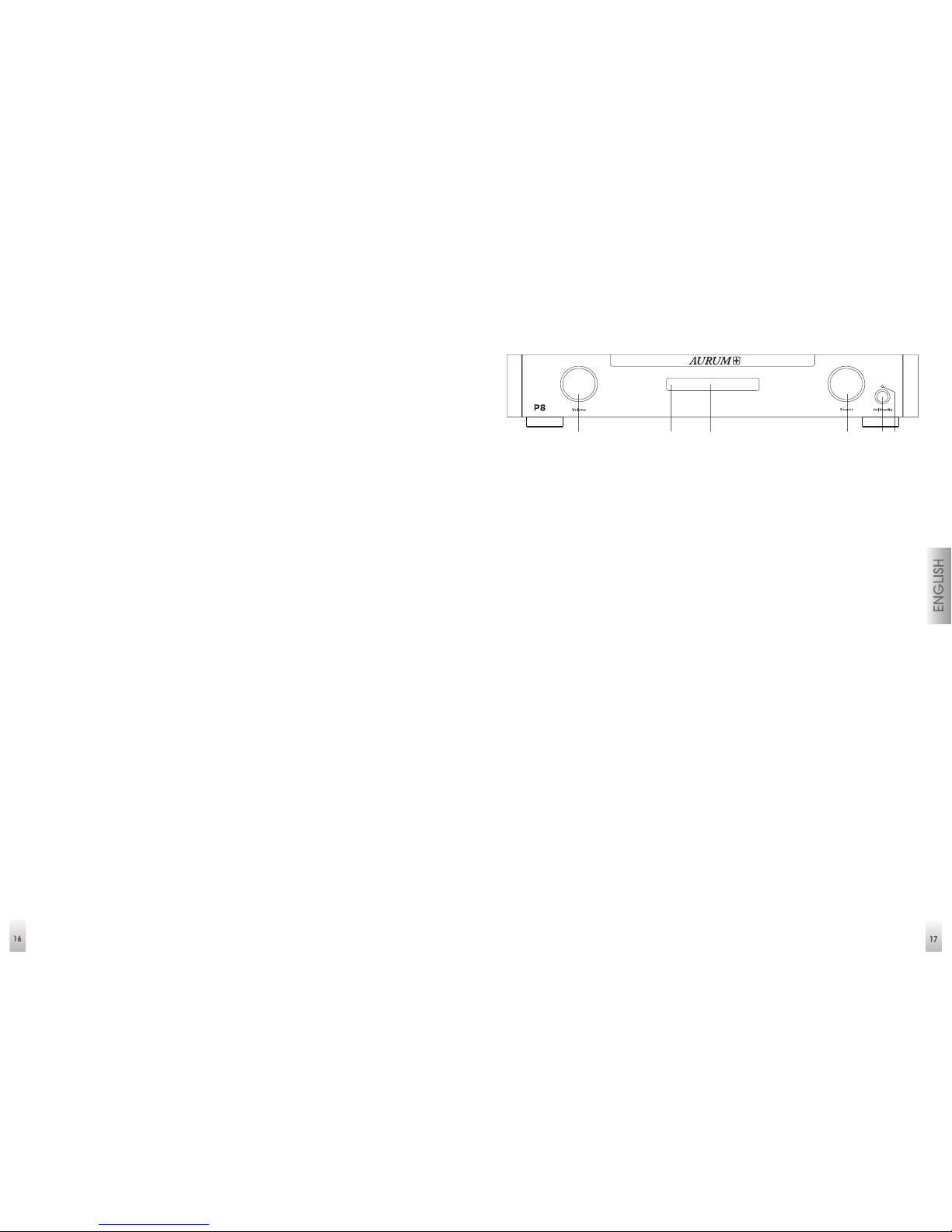
Control elements on the P8 front panel
1 Volume control (Volume): With this rotary control is used to set the volume. The
settings are changed in 1dB increments and are shown in the display.
2 Infrared Receiver: This sensor receives the infrared signals of your remote control.
Always point the remote control at this area, and make sure that the sensor is not
covered up.
3 Display: Here, pieces of status information are displayed that facilitate the
handling of the amplifier.
4 Input Selection (Source / Menu): You may choose the source here by turning
the button left or right. The current source is shown in the display. By pressing the
button, you may access the menus. (Balance/Bass/Levels/SIS/HP). One rotation
of the button within the respective menu item changes the setting.
5 On/Off Button: Press this button to turn the P8 on. Press this button again to turn
the device off (standby). In standby operation, all of the settings remain saved.
6 Operating Display: This display will light up blue if the device is in standby mode
and thus signalizes that you may turn the device back on at any time by pressing
button (2) on the remote control.
Note:
The SIS function serves the purpose of automatically switching off the device
after approx. 15 minutes in case the device does not receive any signal. (Default
setting = Off) If the SIS function is activated on the P8 pre-amplifier and there is a
LINK connection to the M8, then the M8 power amplifier is also switched off.
If there is a LINK connection between P8 and M8, pressing button 5 on the pre-
amplifier, the M8 power amplifier is switched on or off as well.
41 5 62 3
Page 10
18
Using the menu item (HP), the headphone output on the back of the device (rear
panel) is activated or deactivated.
If the headphone output is activated, the signal path to the pre-amplifier outputs
is interrupted!
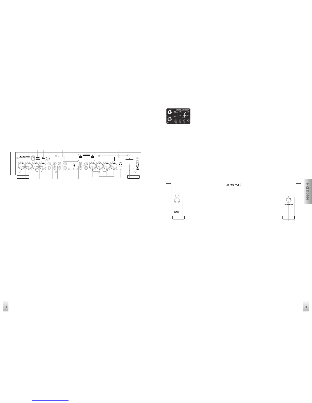
Connections on the P8 rear panel
1 XLR 2 Balanced Inputs
2 XLR 1 Balanced Inputs
3 AUX Analogue inputs for audio signals
4 Tuner Analogue inputs for your radio
5 CD Analogue inputs for CD players
6 Phono Input (MM + MC)
7 Direct Bypass These inputs bypass the audio and volume settings and are
intended for use as part of home cinema installations
8 OUT 3 Unbalanced Outputs
9 OUT 2 Balanced Outputs
10 OUT 1 Balanced Outputs
11 Headphone output Stereo jack socket
12 Power supply socket
13 Power switch Completely disconnects the device from the power supply
14 Ground Phono ground connection
15 SPDIF Co-axial digital input
16 TosLink Optical digital input
Note: PHONO
In order to handle the signal paths for Phono MM (Moving
Magnet) and MC (Moving Coil) as optimally as possible, the
changing between the operating modes is done on the back
side of the devices and individually per channel!
The L1 and R1 switches allow the selection between the MM (switch to the left) and
MC operation. (switch to the right)
The multi-stage switches L2 and R2 offer the option to adjust the impedance for
different MC systems when in the MC operating mode. (Left = 120 Ohm, Centre = 600
Ohm and Right = 40 Ohm)
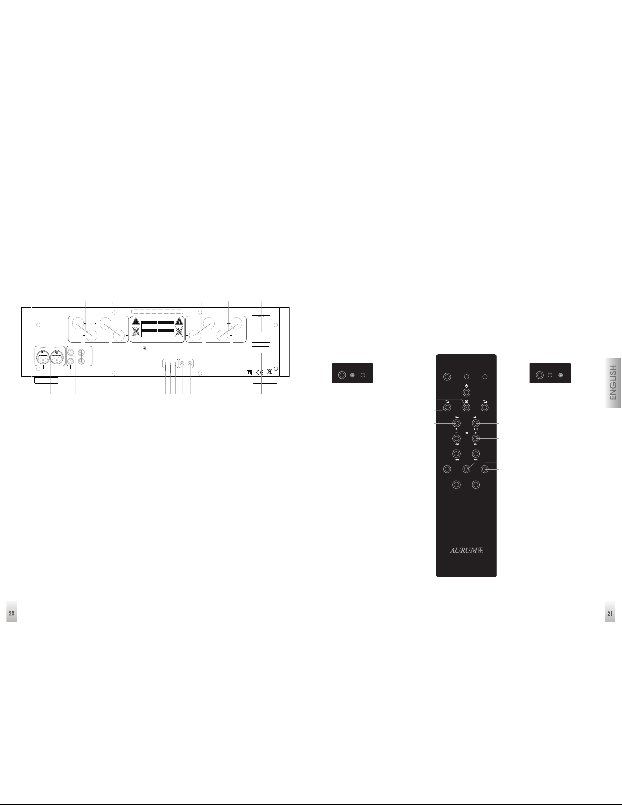
Control elements on the M8 front panel
1 Speakers: Button for speaker switching
Sequence: Group A / B / A+B / OFF
2 LED: Loudspeaker group display
3 Operating Display: This display will light up blue, when the device is turned on and
in operation
4 On/Off Button: Press this button to turn the M8 on. Press this button again to switch
the device off (standby). During standby operation, all of the settings remain
saved.
5 Standby Display: This display is blue whenever the unit is in standby mode and
this indicates that the unit can be switched on again at any time using either the
remote control or button (4)
Fuse:
100V/115V: T250 mA L250V
230V: T125 mA L250V
~50/60 Hz
max. Power Cons.: 10W
quadra l G mbH & Co. KG - Am Herren häu ser B ahnh of 26-28 - D- 30419 Hannover
On
Off
Out 2
L
R
Out 1
LR
Out 3
RLRLR
L
R
L
Aux
Tuner
CD Phono L2 L1R2 R1
Direct
Bypass
40
600
120
R/L 2
MCMMR/L 1
Phono Sw itches
XLR 2
LR
XLR 1
LR
Phono
GND
USB
TosLink
SPDIf
Digital In
Link
Out
Handmade in Germany
W ARNI N G :
TO REDUCE THE RISK
OF ELECTRICAL SHOCK
OR FIRE, DO NOT EXPOSE
THIS APPLIANCE TO
MOISTURE OR RAIN.
DO NOT REMOVE C OVER. NO USER
SERVICEABLE PARTS INSIDE. REFER
SERVICING TO QUALIFIED PERSON NEL.
CAUTION
RISK OF ELECTRIC SHOCK
DO NOT OPEN
1 2 3 4 5 6 7 8 9 10 11 12
131415161718
1 432 5
Page 11
20
Note:
If this display will flash the protection circuit turn off speaker in case of failure or
overload. Reset will be possible if you operate power switch (9) located at back
panel again.
Connections on the M8 rear panel
1 Balanced In Balanced XLR Inputs
2 Unbalanced In Stereo inputs
3 RCA Stereo inputs that may also be used as outputs
4 RCA / XLR Operating mode switch to forward the input signals (2)
for inputs 1 – 3
5 Mono / Stereo Operating mode switch
6 Gain Multi-stage switch used to adjust the input sensitivity.
(+3dB / 0dB / -10dB). Please mind the information pertaining
to the installation/startup.
7 Link In Input for the 12V control connection of the P8
pre-amplifier
8 Link Out Output socket used to forward the control voltage to other
devices
9 Power switch Completely disconnects the device from the power
supply
10 Power supply socket
11 Loudspeaker output A (Left Channel)
12 Loudspeaker output B (Left Channel)
13 Loudspeaker output B (Right Channel)
14 Loudspeaker output A (Right Channel)
Note:
If the buttons 4, 5 and 6 are pressed, there is a pause of about 5 seconds until all
operating points can be stabilized and the signal is released/cleared.
RC 2 Remote Control (OPTIONAL)
The AURUM amplifiers P8 / M8 / A5 / A3 and the AURUM CD players C3 / C5 / C5 DA
may be individually controlled using the RC-2 System Remote Control.
Important note:
If you want to remotely control the amplifier or CD player functions, you must use
the SELECT button to select the relevant operating mode beforehand.
Amplifier operation
1 SELECT button
2 ON / OFF button
3 MUTE
4 Volume - minus
5 Volume - plus
6 Left balance
7 Balance plus
8 Signal source
downwards
9 Signal source
upwards
14 Level setting (for
each input using
buttons 4 & 5)
15 Display brilliance
CD operation
1 SELECT button
2 ON / OFF button
3 MUTE
4 Stop
5 Repeat / Pause
6 Search backwards
7 Search forwards
8 Scan backward
through the titles
9 Scan forward
through the titles
10 File down
11 File forward
12 Repeat (title / all)
13 Shuffle
15 Display brilliance
16 Unassigned
(optional)
Repeat
RL
Select
AMP
CD
Prog.
Opt.
Random
Display
Select
AMP
CD
Select
AMP
CD
1
2
3
4
6
8
10
12
15
5
7
9
11
13
14
16
RC-II
On
Off
max. Power Consumption: 1,
2kW
Fuse:
100V / 115V: T6.3, A L250V
230V:
T3.15, A L250V
CAUTION
RISK OF ELECTRIC SHOCK
DO NOT OPEN
ACHTUNG
STROMSCHLAG GEFAHR
NICHT ÖFFNEN
ATTENTION
RISQUE DE CHOC ELECTRIQUE
NE PAS OUVRIR
ATENCIÓN
RIESGO DE DESCARGA ELCTRICA
NO ABRIR
DO NOT REMOVE C OVER. NO USER-SERVICEABLE PAR TS
INSIDE. REFER SERVICING TO QUALIFIED PERSONNEL.
TO REDUCE THE RISK OF ELECTRICAL SHOCK OR FIRE, DO NOT
EXPOSE THIS APPLIANCE TO MOISTURE OR RAIN.
In Out
Link
Gain
Mono / Stereo
RCA / XLR
+3 / 0
/
-10 dB
quadral GmbH & Co. KG - A m Herrenhäuser B ahnhof 26-28 - D-3041 9 Hannover
Handmade in Germany
®
AURUM
Balanced In
Right
Left
Mono In
Unbalanced In
Right
Left
Mono In
A
B
Right
+ +
Mono
AB
Left
+ +
Mono+
1 2 3 4 5 76 8 9
101112 1314
Page 12
23
Ambient conditions
The remote control has a range of up to 6 m and works without any problems from
a radiating angle of up to 30° in relation to the front of the equipment. Dust on the
transmitter or dirt on the receiving sensor and operating it in the vicinity of fluorescent lights might reduce the range. A direct line-of-sight connection between the
transmitter and the receiver is needed.
Notes about the removal and the correct environmentally-friendly disposal of old
batteries
The symbol shown here can be found on the equipment‘s enclosure,
the packaging as well as in the documents or the operating manual.
It tells you that batteries provided with the equipment as well as those
supplied with or fitted in other units must never be disposed of in house-
hold waste. They must be disposed of in an environmentally-friendly
way (in compliance with the local regulations or European Directives 2002/96/EU
and 2006/66/EU).
You should find out where the nearest collection point for electronic scrap is or
where the recycling site is.
Correct disposal of the equipment and the batteries will help to preserve our
resources and prevent physical and environmental damage. The battery (CR2032)
supplied with the remote control contains lithium and it must be disposed of in an
environmentally-friendly way as described above.
Proceed as described in the following section to replace or remove the battery fitted in the remote control.
1. Undo the screw in the cover underneath the remote control and then remove
the cover.
2. Remove the battery by sliding it out of its holder.
3. You must ensure that the new battery‘s polarity is correct when you fit the new
one! The side of the battery marked with (+) must point upwards so that it makes
contact with the part of the holder marked with (+).
4. Refit the cover and use the screw to secure it in place.
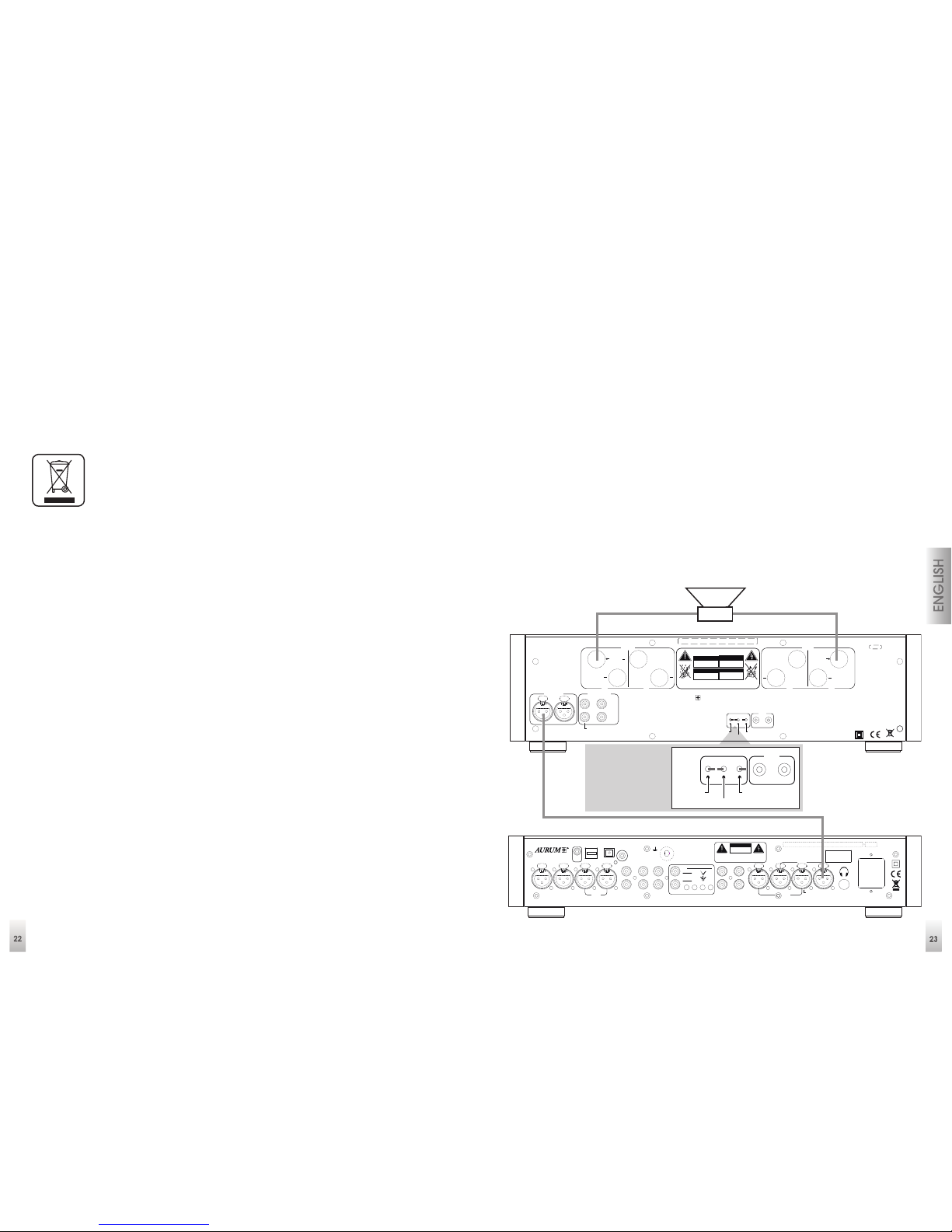
Installing
1. Ensure that the devices are switched off.
2. Connect the devices to the power supply using the accompanying power
cables.
3. Connect the device outputs of the P8 pre-amplifier with the inputs of the M8
power amplifier (ideally, you should use an XLR cable connection for this purpose)
(contact assignment of the XLR connection: Pin 1= ground; Pin 2 = plus / signal;
Pin 3 = minus)
4. You should now connect the source devices at your disposal. (Tuner, CD player,
PC, etc.)
5. If desired, connect the Link-Out socket of the P8 with the Link-In socket of the M8.
6. The speakers are connected using the back-mounted screw terminals depending on the desired operating mode (mono or stereo).
7. You must also ensure that the plus and minus connections on the amplifier concur
with the plus and minus connections on the speakers in order to prevent polarity
reversal.
Mono connection
(Left Channel)
On
Off
max. Power Consumption: 1,
2kW
Fuse:
100V / 115V: T6.3, A L250V
230V:
T3.15, A L250V
CAUTION
RISK OF ELECTRIC SHOCK
DO NOT OPEN
ACHTUNG
STROMSCHLAG GEFAHR
NICHT ÖFFNEN
ATTENTION
RISQUE DE CHOC ELECTRIQUE
NE PAS OUVRIR
ATENCIÓN
RIESGO DE DESCARGA ELCTRICA
NO ABRIR
DO NOT REMOVE C OVER. NO USER-SERVICEABLE PAR TS
INSIDE. REFER SERVICING TO QUALIFIED PERSONNEL.
TO REDUCE THE RISK OF ELECTRICAL SHOCK OR FIRE, DO NOT
EXPOSE THIS APPLIANCE TO MOISTURE OR RAIN.
In Out
Link
Gain
Mono / Stereo
RCA / XLR
+3 / 0
/
-10 dB
quadral GmbH & Co. KG - A m Herrenhäuser B ahnhof 26-28 - D-3041 9 Hannover
Handmade in Germany
®
AURUM
Balanced In
Right
Left
Mono In
Unbalanced In
Right
Left
Mono In
A
B
Right
+ +
Mono
AB
Left
+ +
Mono+
Fuse:
100V/115V: T250 mA L250V
230V: T125 mA L250V
~50/60 Hz
max. Power Cons.: 10W
quadra l G mbH & Co. KG - Am Herren häu ser B ahnh of 26-28 - D- 30419 Hannover
On
Off
Out 2
L
R
Out 1
LR
Out 3
RLRLR
L
R
L
Aux
Tuner
CD Phono L2 L1R2 R1
Direct
Bypass
40
600
120
R/L 2
MCMMR/L 1
Phono Sw itches
XLR 2
LR
XLR 1
LR
Phono
GND
USB
TosLink
SPDIf
Digital In
Link
Out
Handmade in Germany
W ARNI N G :
TO REDUCE THE RISK
OF ELECTRICAL SHOCK
OR FIRE, DO NOT EXPOSE
THIS APPLIANCE TO
MOISTURE OR RAIN.
DO NOT REMOVE C OVER. NO USER
SERVICEABLE PARTS INSIDE. REFER
SERVICING TO QUALIFIED PERSON NEL.
CAUTION
RISK OF ELECTRIC SHOCK
DO NOT OPEN
– +
Switch position XLR
and Mono at - 10dB
XLR left channel
On
Off
max. Power Consumption: 1,
2kW
Fuse:
100V / 115V: T6.3, A L250V
230V:
T3.15, A L 250V
ACHTUNG
STROMSCHLAG GEFAHR
NICHT ÖFFNEN
ATENCIÓN
RIESGO DE DESCARGA ELCTRICA
NO ABRIR
-
SERVICEA BLE PARTS
In Out
Link
Gain
Mono / Stereo
RCA / XLR
+3 / 0
/
-10 dB
AB
Left
+ +
Mono+
Page 13
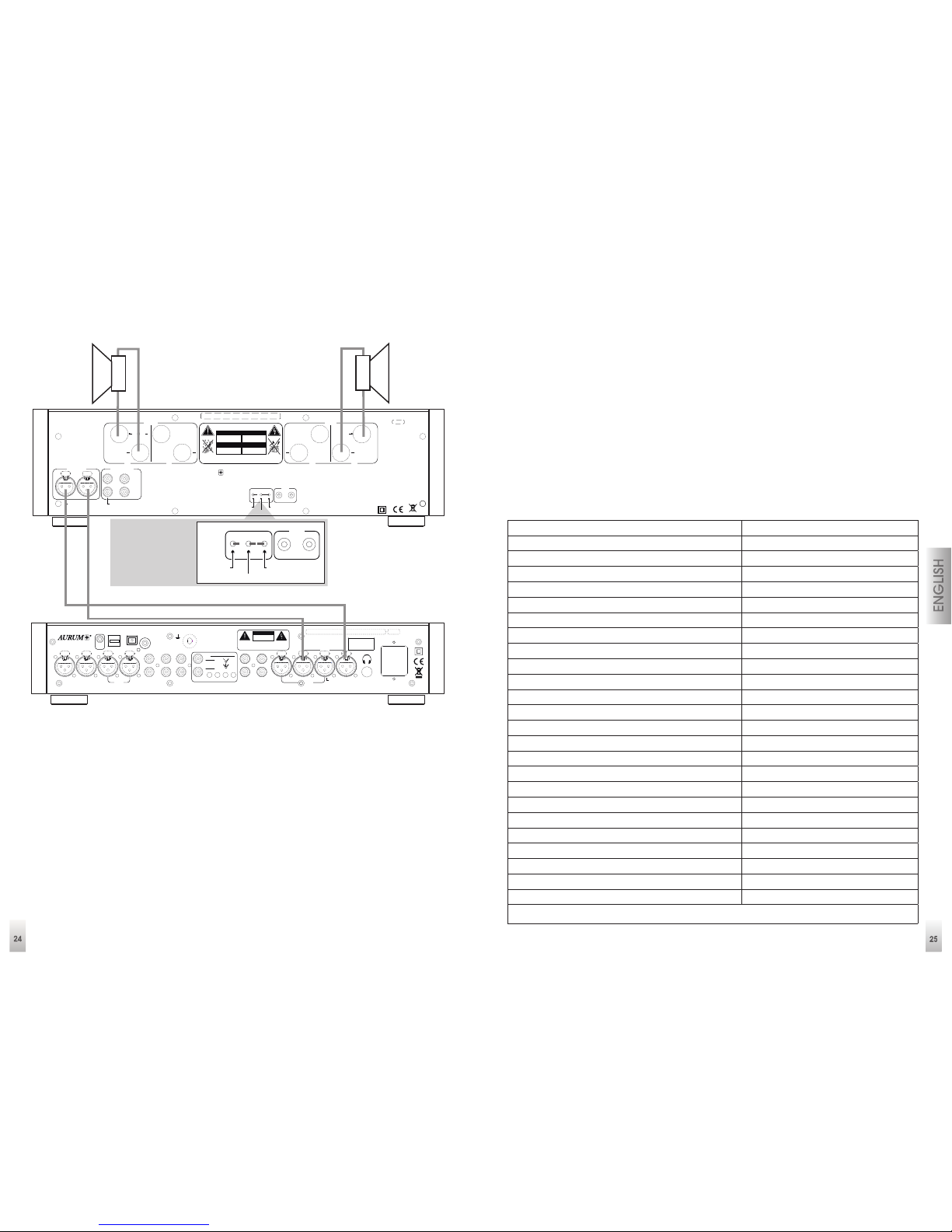
25
Stereo connection
(speaker A)
8. You may now switch your M8 and P8 devices on using the power switches.
9. Move the M8 power switch (9) and P8 power switch (13) on the back sides of the
devices to the ON position. The standby LEDs on the front panels will now come
on.
10. Now press the On / Standby button (5) on the front of the P8 pre-amplifier or
the button (2) on the remote control to start your devices. The M8 is switched on
together with the P8, if there is a LINK connection between them.
11. If there is no LINK connection, you additionally have to press button (4) on the M8
front panel.
Note:
As your P8 / M8 uses a special power-saving standby circuit, you can always
switch on / off during normal operation using the On / Standby button on the unit
or the RC-2 remote control.
The RC-2 remote control makes it easier for you to change
your settings.
Mute (button 3)
Balance setting (buttons 6 & 7)
Multi-level adjustment of display brightness (button 15 / only for P8, A5, A3)
Input level setting for all inputs (button 14)
Example: Input level adjustment
Use buttons 8 (-) or 9 (+) to select the signal source and then press button 14 (Prog.)
and use the volume buttons (4 & 5) to set up the input volume to suit yourself. Press
button 14 (Prog.) once again to save the settings.
Technical Data M8
Input sensitivity for 1 W at 4 ohms -26 dBV
Input impedance 47 kOhm
Voltage gain 22/32/35 dB
Maximum input voltage 6 V
Maximum voltage at speaker output (Stereo) 50 V
Maximum voltage at speaker output (Mono) 70 V
Minimum loudspeaker impedance (Stereo) 2 ohms
Minimum loudspeaker impedance (Mono) 2 ohms
Stereo output power at 8 ohms 120 W
Stereo output power at 4 ohms 200 W
Mono output power at 8 ohms 240 W
Mono output power at 4 ohms 350 W
Frequency response 1 Hz - 110 kHz (-3 dB)
Harmonic distortion < 0.03%
A-weighted signal-to-noise ratio 85 dB
Mains power connection 115V / 230V, switchable
Power consumption (in normal mode) 25 W
Power consumption (at maximum volume) max. 1200 W
Power consumption (in standby mode) < 0.5W
Inputs 2 pairs of RCA, 1 pairs of XLR
Speaker outputs 2 x pair
12V Link Connection In + Out (short-circuit-proof) 3.5mm Mono minijack
Protective circuits Temperature, overload
Dimensions (W x H x D) 453 x 130 x 330 mm*
Weight 1,38kg
* Width including wooden sides, Height including feet, Depth with speaker terminals
Switch position
XLR and Stereo
On
Off
max. Power Consumption: 1,
2kW
Fuse:
100V / 115V: T6.3, A L250V
230V:
T3.15, A L 250V
ACHTUNG
STROMSCHLAG GEFAHR
NICHT ÖFFNEN
ATENCIÓN
RIESGO DE DESCARGA ELCTRICA
NO ABRIR
-
SERVICEA BLE PARTS
In Out
Link
Gain
Mono / Stereo
RCA / XLR
+3 / 0
/
-10 dB
AB
Left
+ +
Mono+
Fuse:
100V/115V: T250 mA L250V
230V: T125 mA L250V
~50/60 Hz
max. Power Cons.: 10W
quadra l G mbH & Co. KG - Am Herren häu ser B ahnh of 26-28 - D- 30419 Hannover
On
Off
Out 2
L
R
Out 1
LR
Out 3
RLRLR
L
R
L
Aux
Tuner
CD Phono L2 L1R2 R1
Direct
Bypass
40
600
120
R/L 2
MCMMR/L 1
Phono Sw itches
XLR 2
LR
XLR 1
LR
Phono
GND
USB
TosLink
SPDIf
Digital In
Link
Out
Handmade in Germany
W ARNI N G :
TO REDUCE THE RISK
OF ELECTRICAL SHOCK
OR FIRE, DO NOT EXPOSE
THIS APPLIANCE TO
MOISTURE OR RAIN.
DO NOT REMOVE C OVER. NO USER
SERVICEABLE PARTS INSIDE. REFER
SERVICING TO QUALIFIED PERSON NEL.
CAUTION
RISK OF ELECTRIC SHOCK
DO NOT OPEN
On
Off
max. Power Consumption: 1,
2kW
Fuse:
100V / 115V: T6.3, A L250V
230V:
T3.15, A L250V
CAUTION
RISK OF ELECTRIC SHOCK
DO NOT OPEN
ACHTUNG
STROMSCHLAG GEFAHR
NICHT ÖFFNEN
ATTENTION
RISQUE DE CHOC ELECTRIQUE
NE PAS OUVRIR
ATENCIÓN
RIESGO DE DESCARGA ELCTRICA
NO ABRIR
DO NOT REMOVE C OVER. NO USER-SERVICEABLE PAR TS
INSIDE. REFER SERVICING TO QUALIFIED PERSONNEL.
TO REDUCE THE RISK OF ELECTRICAL SHOCK OR FIRE, DO NOT
EXPOSE THIS APPLIANCE TO MOISTURE OR RAIN.
In Out
Link
Gain
Mono / Stereo
RCA / XLR
+3 / 0
/
-10 dB
quadral GmbH & Co. KG - A m Herrenhäuser B ahnhof 26-28 - D-3041 9 Hannover
Handmade in Germany
®
AURUM
Balanced In
Right
Left
Mono In
Unbalanced In
Right
Left
Mono In
A
B
Right
+ +
Mono
AB
Left
+ +
Mono+
– +
– +
XLR Stereo connection
Page 14

26
Technical Data P8
Input impedance (XLR) 47 kOhm
Input sensitivity (XLR) 100mV
Signal-to-noise ratio (XLR) A-weighted 94 dB
Input impedance (Line) 47 kOhm
Input sensitivity (Line) 100mV
Signal-to-noise ratio (Line) A-weighted 94 dB
Input impedance Phono MM 47 kOhm
Input sensitivity Phono MM 2.6mV
Signal-to-noise ratio (Phono MM) A-weighted 90 dB
Input impedance Phono MC 40 / 120 / 600 Ohm
Input sensitivity Phono MC 0.26mV
Signal-to-noise ratio (Phono MC) A-weighted 74 dB
Voltage amplification (Line) 45 dB
Maximum input voltage (Line) 6V
Maximum voltage at XLR output 15V
Output impedance (XLR) 300 ohms
Maximum voltage at RCA output 8 V
Output impedance (RCA) 600 ohms
Volume adjustment range 99 dB
Control range for Balance, Bass, Levels ± 6 dB
Gain adjustment range - 6 dB
Adjustment accuracy 0.1 dB
Channel balance better than 0.05 dB
Frequency response 1Hz-110kHz (-3dB)
Harmonic distortion < 0.03%
Stereo headphone output 6.3mm / 600 Ohm
12V Link Connection (short-circuit-proof) 3.5mm Mono minijack
SIS (Auto On/off) after 15 minutes without a signal
Mains power connection 115V / 230V, switchable
Power consumption (in normal mode) 10 W
Power consumption (in standby mode) < 0.5W
Analogue inputs 4 pairs of RCA, 2 pairs of XLR, 1 pair of
Phono
Digital inputs (24bit / 192KHz) 1 x Optical / 1x Co-axial
USB 1 x USB / Type B (48KHz)
Outputs 2 pairs of XLR, 1 pairs of RCA
Dimensions (W x H x D) 453 x 82 x 330 mm *
Weight 5,3kg
* Width including wooden sides, Height including feet, Depth with speaker terminals
Page 15

dtp-Realisation · 944223 · 07/2013
Ein Unternehmensbereich der quadral GmbH & Co. KG
Am Herrenhäuser Bahnhof 26-28
D-30419 Hannover
Phone: +49 (0) 511 - 79 04 - 0
Fax: +49 (0) 511 - 79 04 - 444
e-mail: [email protected]
Internet: www.aurumelectronic.com
facebook.com/quadralhifi
 Loading...