

Page 1
1
Table of Contents
1 Introduction
1 Unpacking and Repacking
1 Placement
2 Front Panel Features and Definitions
7 Back Panel Features and Definitions
11 CD Transport Mechanism Operation
13 Integris CDP R-676 Remote Control
17 Menu – Optional User-Settings
23 Specifications
24 Warranty
Aurum Acoustics
10 Minerals Road
Conception Bay South
Newfoundland and Labrador
Canada
A1W 5A1
Tel: 709 834 8244
Fax: 709 834 8246
www.aurumacoustics.com
INTEGRIS CDP – Owner’s Reference Guide
Page 2

1
Introduction
Thank you for your purchase of the Integris CDP Compact
Disc Player and Linestage Preamplifier. This Owner’s
Reference Guide contains information that will permit you
to obtain maximum performance and utility from the
Integris CDP’s extensive features.
Unpacking and Repacking
Do not discard any packing materials! You will need them
to transport the unit, should that be necessary. Shipping
without all proper packaging materials may result in
damage.
.
1. Open the box along the top flaps and remove the
top section of protective foam. Remove and set
aside the bubble envelop of small parts.
2. Reach around the sides of the unit and lift straight
out of the shipping box.
3. Remove the unit from its clear poly bag without
tearing the bag. Placing it on a soft but secure
surface can make removal easier.
4. Remove the transport bay foam insert. You may
wish to leave it in place until the unit has been
placed in its final location – this will keep the lid in
place during any further movement of the unit.
5. Carefully open one end of the small-parts bubble
envelope and remove its contents:
• Magnetic transport disc clamp
• Integris R-676 remote
• 4 AAA alkaline batteries
• USB cable
Remove all items from their sub-packaging. Place
the small item packaging back in the bubble
envelope.
6. Place the small-parts envelope, transport foam
insert, and the box’s top foam section back inside
the box. Close the box and store in a dry area.
Placement
The Integris CDP employs a top-loading CD transport that
requires sufficient space above it for a user to comfortably
load and remove discs and the disc clamp. Ideally the
Integris CDP should be placed on a top shelf or where a
generous clearance exists.
For optimal placement, put the Integris CDP on a firm level
shelf away from heat, humidity, moisture, and vibration.
Avoid direct exposure to sunlight.
While stacking components on top of the Integris CDP is
not possible, if necessary, the unit may be placed on top
of other components. The user should be certain that any
supporting components provide a stable and inert
platform.
Page 3
2
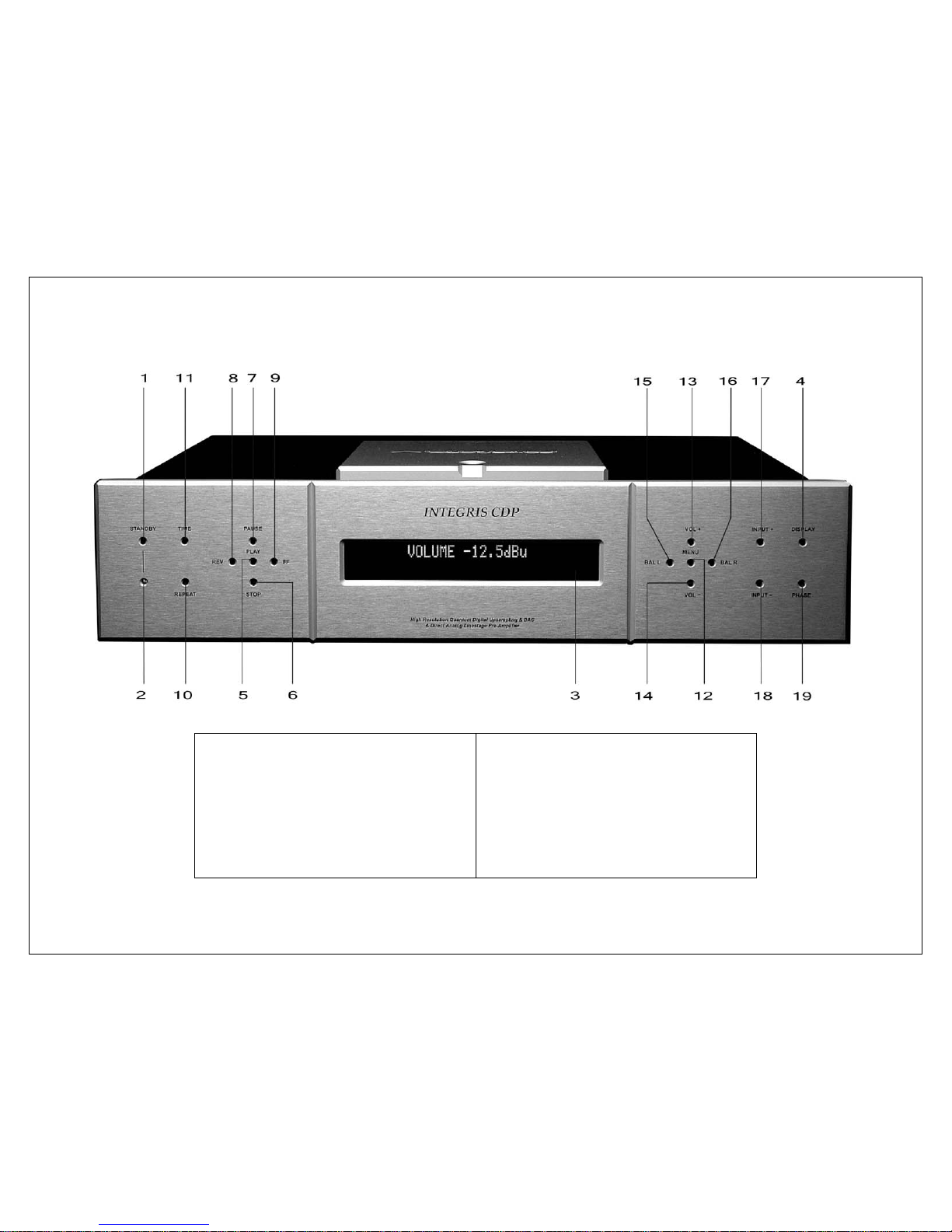
FRONT PANEL FEATURES AND DEFINITIONS
1 STANDBY SELECTOR
2 STANDBY LED
3 VACUUM FLUORESCENT DISPLAY
4 DISPLAY DIMMER
5 CD PLAY
6 CD STOP
7 CD PAUSE
8 CD SCAN/SKIP REVERSE
9 CD SCAN/SKIP FORWARD
10 CD REPEAT
11 CD TIME
12 MENU
13 VOLUME UP
14 VOLUME DOWN
15 BALANCE LEFT
16 BALANCE RIGHT
17 INPUT SCROLL FORWARD
18 INPUT SCROLL REVERSE
19 PHASE INVERSION
Page 4

3
Front Panel Features and Definitions
1. Standby Selector (STANDBY)
The STANDBY button changes the Standby mode from
Standby to Operate.
In Standby, the Integris CDP is in a partial sleep mode as
an alternative to turning its power fully off via the rear
panel mains switch. All circuits are left on and warm for
maximum performance upon immediate use. The unit is
non-responsive to all commands except another push of
the STANDBY button.
Upon returning to the Operate mode, the same Volume,
Balance, and Input settings remain in effect as when
entering Standby.
2. Standby LED
In Standby mode, the blue LED is on. In Operate mode,
the LED is off.
3. Vacuum Fluorescent Display
The VFD provides two rows of bright and clear dot-matrix
text. The VFD informs the operator of preamp settings,
CD transport playback, and provides real-time
acknowledgement of user commands.
4. Display Dimmer (DISPLAY)
The VFD’s intensity can be adjusted to suit lighting
conditions and user preference using the DISPLAY button.
With each press of the DISPLAY button, a message on the
VFD will briefly advise the setting selected.
In the 0% or Display Off setting, commands will briefly be
confirmed on the display at a 25% intensity level.
DISPLAY Settings
100 %
75 %
50 %
25 %
0 %
5-11 CD Transport Controls
5. CD Play (PLAY)
The PLAY function is available after a CD’s table of
contents has successfully loaded. Use PLAY to start a disc
or to remove the disc from Pause mode. During play
mode,
► will appear in the lower right of the display.
6. CD Stop (STOP)
STOP will bring the transport to a complete stop from Play
or Pause mode.
7. CD Pause (PAUSE)
During CD playback, the PAUSE button will hold disc
playback from advancing but the transport will continue
to spin. Play is resumed by pressing the PLAY button.
Track Skip is available in Pause mode. While in pause
, ▌▌
appears in the display.
Page 5
4
8. CD Scan/Skip Reverse (REV)
9. CD Scan/Skip Forward (FF)
These buttons enable two functions during CD playback:
• Track Skip – Apply a momentary contact of
approximately ¼ second or less to the REV or FF
buttons to have the transport return to the beginning
of the track already playing (REV) or advance to the
beginning of the next track (FF). Press repeatedly to
skip by several tracks.
• Scan – Hold either button down for 1 second or more
to move within a track. Initial scanning rate is 3X
normal speed and increases to 15X when held for
several seconds. One of the reverse or forward scan
symbols,
<<<, <<, >>, >>>, will appear on the display.
10. CD Repeat (REPEAT)
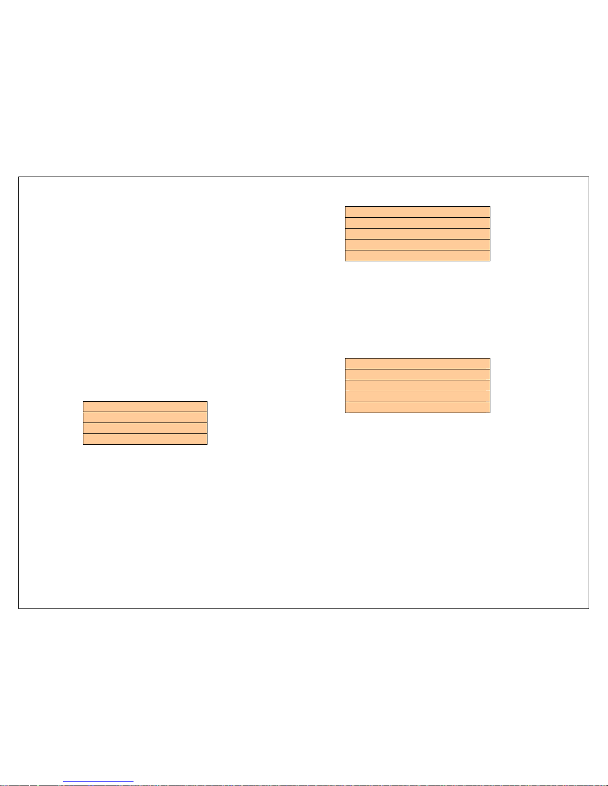
Three Repeat options are available:
REPEAT Settings
No repeat
Single track repeat
Full CD repeat
Pressing the REPEAT button will scroll continuously through
the options. Each choice is briefly shown on the display
after the button is pressed. The last option shown is the
Repeat mode selected.
11. CD Time (TIME)
The TIME button provides four options for real-time display
information during CD operation. Each choice is briefly
shown on the display after the button is pressed. The last
option shown is the CD Time mode selected.
TIME Settings
Elapsed track time
Remaining track time
Elapsed total CD time
Remaining total CD time
12-18 Preamplifier Controls
12. Menu (MENU)
The MENU button accesses a sophisticated set of usercustomizable features:
MENU setup areas
Input Name Setting
Analog Level Trim
Volume Control Bypass
Preferences Save and Reset
These are extensively explained in the MENU – Optional
User Settings section of this Guide.
13. Volume Up (VOL +)
14. Volume Down (VOL -)
VOL+ and VOL- will incrementally raise or lower the
preamp volume control within a range of -60dBu to
+20dBu. Lowering the volume to below -60dBu mutes the
circuit: the display will provide a VOLUME MUTE message.
In normal use, the Volume setting is always shown on the
top line of the display regardless of Input selection.
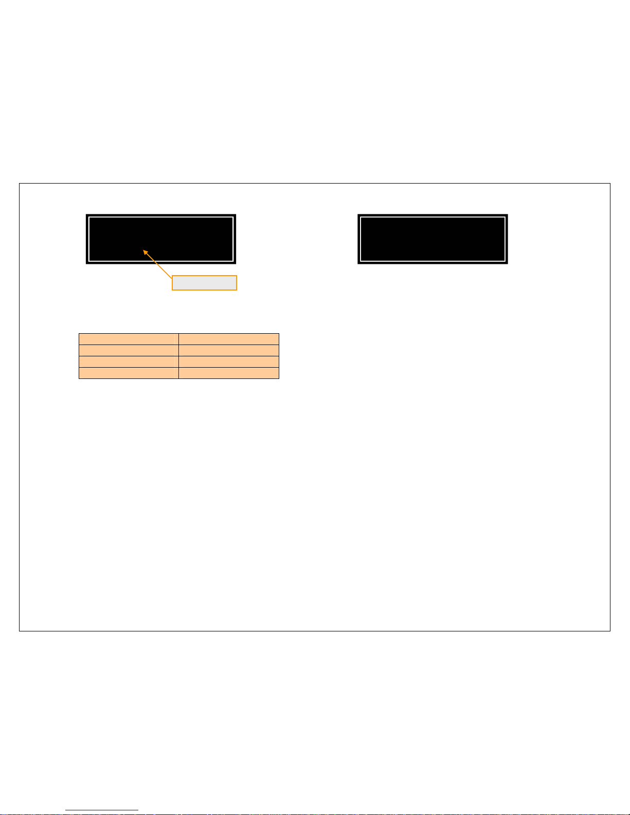
During adjustment, a visual volume bar-scale appears
temporarily on the display’s bottom row to further aid in
setting the volume level:
Page 6
5
Single presses of the VOL buttons will result in changes
relative to the Volume setting range:
Volume range Setting Change
-20 to +20 dBu 0.5dB
-40 to -20 dBu 1.0dB
-60 to -40 dBu 2.0dB
Holding the buttons continuously will temporarily increase
the size of the volume control increments to allow for
rapid volume adjustment.
15. Balance Left (BAL L)
16. Balance Right (BAL R)
Each press of the BAL L or BAL R buttons decreases the
opposite channel output in 0.5dB increments. From a
nominal center balance position of 0dB, the maximum
cut is -6dB. Pressing beyond -6dB puts the lowered
channel into full MUTE mode. To restore the balance
toward the nominal center position or beyond, press the
opposite balance button.
Balance settings are held on the display for two seconds,
and appear such as this example for a reduction in Leftchannel output:
17. Input Scroll Forward (INPUT +)
18. Input Scroll Reverse (INPUT -)
The Integris CDP has a total of 11 source Input options
including the integral CD transport:
CD
UNBALANCED 1
UNBALANCED 2
UNBALANCED 3
BALANCED 1
BALANCED 2
S/PDIF 1
S/PDIF 2
BNC
AES/EBU
TOSLINK
These names may be personalized. Refer to the MENU –
Optional User Settings section.
The user may select from all sources in sequence using
the INPUT+ and INPUT- buttons to scroll through the list.
The Input list is continuously looped. All Inputs may be
reached by pressing either button.
19. Phase Inversion (PHASE)
The PHASE button allows the user to alternate the
absolute electrical and acoustic polarity of a signal from
any Input. The choice of 0˚ or 180˚ will be shown briefly
on the display.
VOLUME – 5.0dBu
I I I I I I I I I I I I I I I
BALANCE
LEFT –2.5dB
Page 7
6
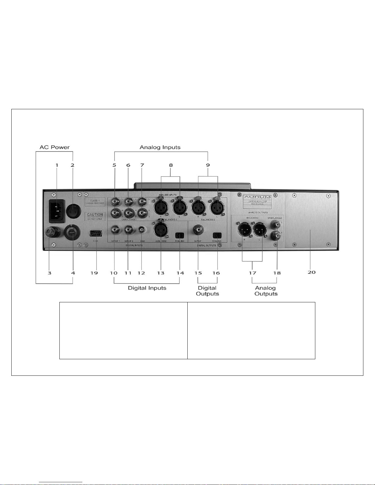
Back Panel Features and Definitions
1 MAINS POWER INLET
2 POWER SWITCH
3 MAINS POWER FUSE -1/4 A
4 VOLTAGE SELECTOR
5 UNBALANCED INPUT 1
6 UNBALANCED INPUT 2
7 UNBALANCED INPUT 3
8 BALANCED INPUT 1
9 BALANCED INPUT 2
10 DIGITAL INPUT S/PDIF 1
11 DIGITAL INPUT S/PDIF 2
12 DIGITAL INPUT BNC
13 DIGITAL INPUT AES /EBU
14 DIGITAL INPUT TOSLINK
15 DIGITAL OUTPUT S/PDIF
16 DIGITAL OUTPUT TOSLINK
17 BALANCED OUTPUT
18 UNBALANCED OUTPUT
19 COM PORT
20 EXPANSION SLOT
Page 8

7
Back Panel Features and Definitions
1-4 Mains Power Panel
The Integris CDP is designed for use with all major AC
power systems. The unit has built-in RFI filtering for
superior performance.
1. Mains Power Inlet
A power cord with an IEC 10-15Amp female plug is
required to connect AC power to the Integris CDP. We
recommend quality aftermarket power cords and direct
connection to a quality AC outlet for best performance.
2. Power Switch
The mains rocker switch illuminates in the On position.
The mains switch may be used to isolate all of the Integris
CDP’s internal circuits from AC power.
3. Mains Power Fuse –
¼ A
The fuse is a 0.25 x 1.25 inch slow-blow type rated at
1/4Amp/250V. Replace only with the same type and
value.
4. Voltage Selector
Confirm that the voltage selector is set to the nearest
standard voltage in your area. All products should be
delivered preset to the correct voltage but exceptions
can occur. Do not connect power until you are certain
of the correct voltage setting.
5-9. Analog Preamp Inputs
The analog preamplifier section of the Integris CDP has
five line-level buffered Inputs. Highest quality
components are used to allow external sources to
achieve their maximum potential.
5-7. Unbalanced Inputs 1-3
These three inputs accept signals via unbalanced RCAequipped interconnect cables, the most common type
in use. The Integris CDP’s RCA jacks are premium high
performance components from cabling specialist Cardas
Audio.
8-9. Balanced Inputs 1-2
These two inputs accept signals via balanced XLRequipped interconnect cables.
10-14. Digital Inputs
The Integris CDP has five digital inputs that accept PCM
(pulse code modulated) signals from 32kHz-192kHz at 1624 bit word length for two-channel playback. Examples
of these sources include CD transports, DVD-Audio, DAT
decks, and many PC-based applications. All digital
inputs are routed through the Quantum resampler and
Delivered to the onboard DAC (digital to analog
converter) at a sample rate of 24 bit/192kHz.
Switching off power will reset all userconfigurable operating parameters to
factory default or to the last saved usersettings, if present.
Page 9

8
10-11. S/PDIF 1-2
These connections accommodate the most common
digital interconnect interface using RCA-connector
equipped cables and 75ohm load impedance. These
Inputs also accommodate PCM sample rates different
than the S/PDIF standard of 16 bit/44.1kHz.
12. BNC
This connection is essentially the same as S/PDIF 1-2 but
with an alternate cable connector, the BNC.
13. AES/EBU
This is a balanced digital connection, as found on some
digital sources requiring an XLR equipped digital
interconnect and 110ohm load impedance.
14. TOSLINK
This input allows connection to a source with Toslink (EIAJ)
optical transmission of the standard S/PDIF digital signal.
15-16. Digital Outputs
The digital outputs are monitoring loops that allow return
of the digital signal input to the source or to a secondary
component or system.
These signals are returned at the native sampling rate at
which they are received: Quantum resampling is not
applied. The internal CD transport is available from these
outputs at the standard sampling rate of 16 bit/44.1kHz.
15. S/PDIF
This connection accommodates the most common
digital interconnect interface using an RCA-connector
equipped cable and 75ohm load output impedance.
16. TOSLINK
This output allows connection to a receiver with Toslink
(EIAJ) optical transmission.
17-18. Analog Outputs
The preamplifier’s analog outputs are capable of
properly driving virtually all audio power amplifiers. Their
buffered outputs provide low output impedance and
high current capability to drive both high- and lowimpedance loads. All signals are managed by the
volume control circuit unless the Volume Control Bypass
feature is enabled – see the MENU – Optional User
Settings section. Balanced and unbalanced signal
outputs may be used individually or simultaneously.
17. Balanced Outputs
This connection type, requiring XLR-equipped analog
interconnects, is recommended when connecting to
power amplifiers with fully-differential circuits. It may also
be preferred in EMI/RFI prone environments or for
especially long cable runs.
18. Unbalanced Outputs
This connection type, requiring RCA-equipped analog
interconnects, is the most common cable and connector
Non-PCM signals are not accommodated: these
include DSD and other one-bit formats as well as
compressed formats such as MP-3 and Dolby
Digital.
Page 10

9
type found on audio amplifiers. These outputs, using
connectors from Cardas Audio, provide a very high level
of performance in most situations.
19-20. Upgrade Potential
Aurum Acoustics has designed the Integris CDP to be
modular, expandable, and upgradeable. The internal
digital and analog systems are designed for possible
upgrades and enhancements. Other new hardware
and software applications may be created for the
Integris CDP to increase its performance and utility. With
the COM Port and Expansion Panel, the user will have the
option to self-install new offerings. Check
www.aurumacoustics.com and with your Aurum
Acoustics retailer for developments.
19. COM Port
Firmware upgrades can be made via connection of this
RS-232 serial port to a PC. As needed, Aurum Acoustics
will make available software and instructions allowing the
user to execute a firmware update. Presently there are
no user-accessible features serviceable via the COM
Port.
20. Expansion Panel
The area behind the expansion panel is presently an
unused space available for adding new hardware
options. Aurum Acoustics may develop high
performance accessory modules permitting even
greater integrated capabilities from within the Integris
CDP platform.
Page 11
10
CD Transport Mechanism Operation
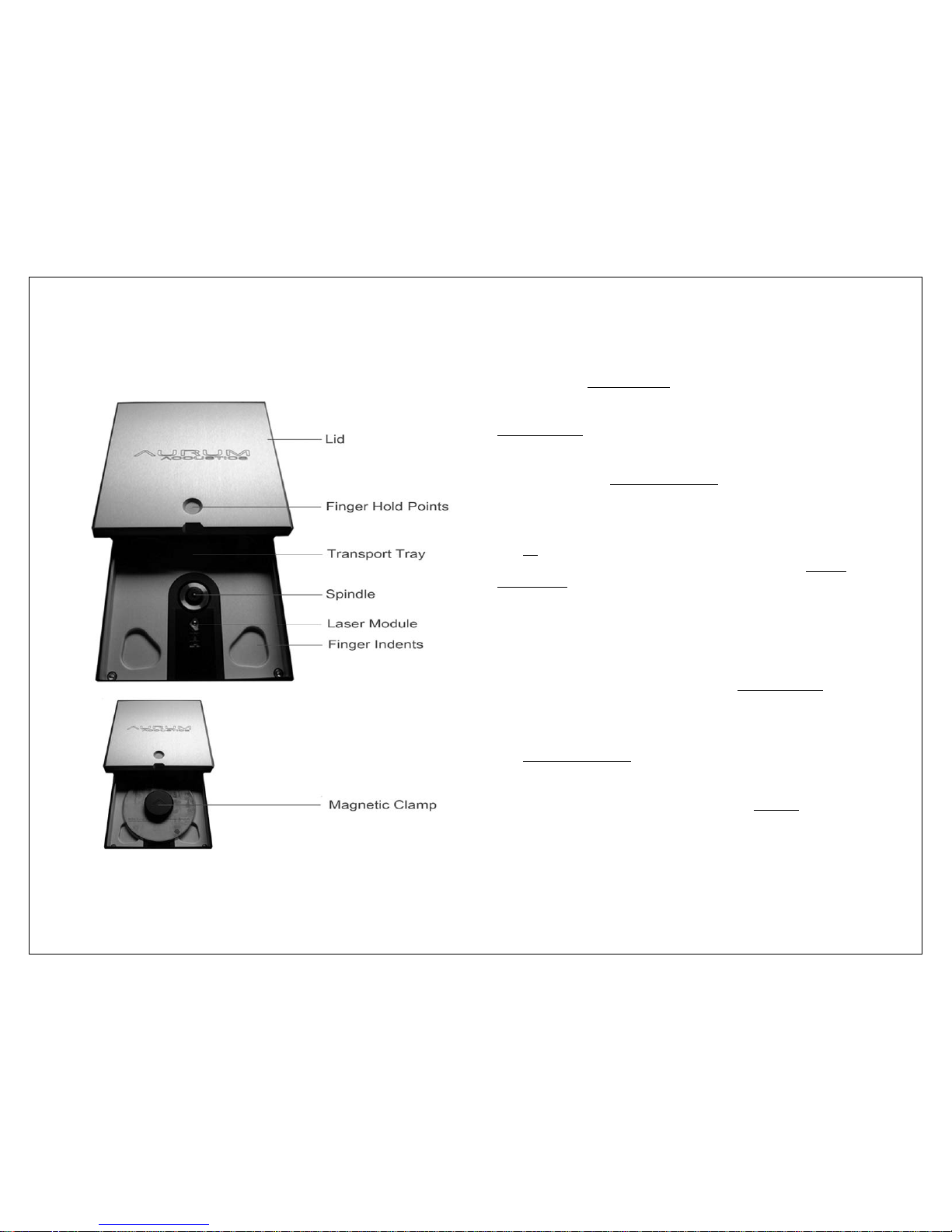
The internal CD transport is designed to deliver the finest
performance possible from the CD format. It uses the
robust and accurate top-loading Philips CDPro-2M
transport and laser module
on an Aurum Acousticsdesigned mechanical isolation system. The transport
module is secured to a massive machined aluminum
transport-tray
for inertial stability. The transport-tray floats
above the bottom panel on flexible mounts and is held
completely independent of the top panel and lid. The
manually placed magnetic clamp
further ensures total
transport system isolation from the chassis.
1. Lid Operation
The lid requires manual operation. Use the circle and
notch indentations on the front end of the lid as fingerhold points to gently slide it forward and backward. The
robust slider mechanism utilizes Teflon rods that will never
need adjusting under normal use.
2. Disc Placement and Removal
With the lid open, hold a CD by its outer edge and lower
it onto the transport spindle. The four finger indents
allow
correctly placed fingers to do this comfortably.
3. Clamp Placement
The magnetic clamp is precisely machined from
aluminum to provide steady inertia, clamping force, and
damping for accurate disc reading. It should be gently
placed onto the center of the transport spindle
.
4. Transport Initialization
When you close the lid, the transport initializes the disc
and reads its table of contents. Initialization requires
several seconds to complete and is not the same for all
CDs. Discs with many tracks take more time to read.
Page 12
11
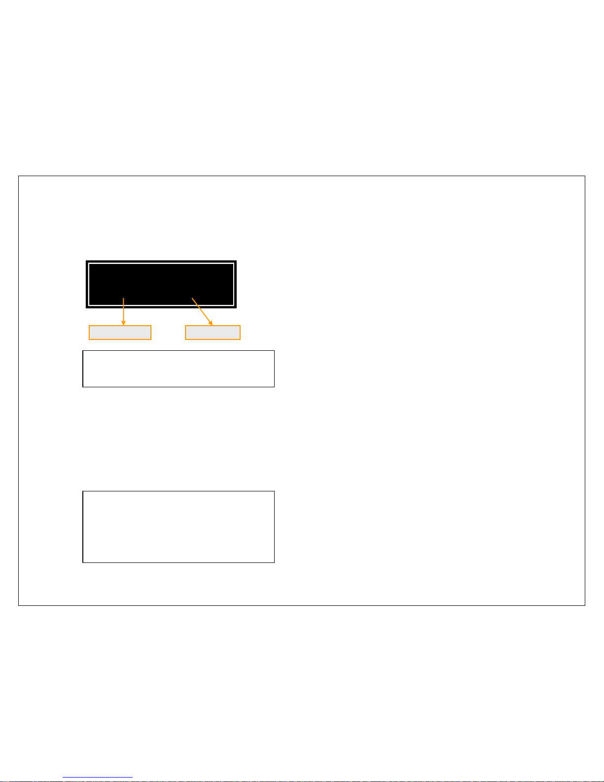
The VFD will show the general parameters of the CD
including number of tracks and total disc time as per the
graphic below. This is also the default display mode for
CDs in Stop mode.
CD transport commands can now be applied from the
remote or front panel control.
If the disc has failed to initialize properly, the VFD will
deliver a NO DISC message. If any unusual noise was
heard during the attempted initialization, the disc and
clamp may not have been placed properly. Readjust
the positioning of disc and clamp and close the lid.
5. Disc Removal
First ensure the transport has stopped. This can be
verified by confirming the default Stop mode display.
Slide the lid open, remove the clamp, and then reach
into the finger indents and lift the disc by its outer edge.
If not replacing with another CD, close the lid to protect
the transport. Do not store the clamp in the transport
bay without a CD in place.
Only properly encoded CDs will be
recognized: other disc types and CDs
burned with non-Redbook format data will
not be recognized.
SACDs will be playable if a Redbookcompatible layer is present.
VOLUME – 20.dBu
[11] 39:05
TOTAL TRACKS TOTAL TIME
Ensure that the CD Input is selected. The
transport will not respond and remains idle
unless the CD In
p
ut is selected.
Page 13
12
Integris CDP R-676 Remote Control
Overview
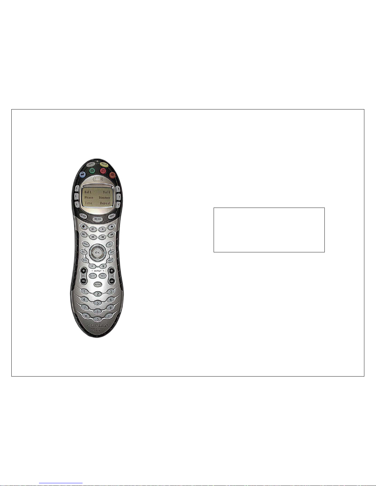
The Integris CDP R-676 remote control handset was
developed in conjunction with Logitech Harmony, a
leader in multi-function remote control solutions.
Aurum Acoustics has programmed the remote with a
command set tailored for easy control of the Integris
CDP. The instructions that follow are limited to the
operation of the Integris CDP.
The remote’s infrared transmitter system allows one way
communication only. The user must watch the main
unit’s VFD for visual feedback of commands sent via
remote.
Users may freely install and customize
programming for additional devices.
Refer to the Logitech Harmony website,
www.logitech.com, for instructions. The
supplied USB cable is required only for
this purpose.
Page 14
13
Batteries
A set of 4 AAA 1.5V alkaline batteries is included. Under
general use, battery life expectancy is approximately 3
months. Alkaline batteries are the recommended
replacement.
The remote will provide a Replace Battery message after
the operating voltage drops to a critical level. From this
point on, weak batteries may continue to provide
operation for several days; however full LCD display
capability is lost and the infrared transmitter will not
perform at its best.
Initial Turn-on and Standby
After inserting batteries, press the red button near the top
of the remote embossed with the music-note
♫. This is
the Standby On button. It will
prompt the remote to activate its
preprogrammed codes for the
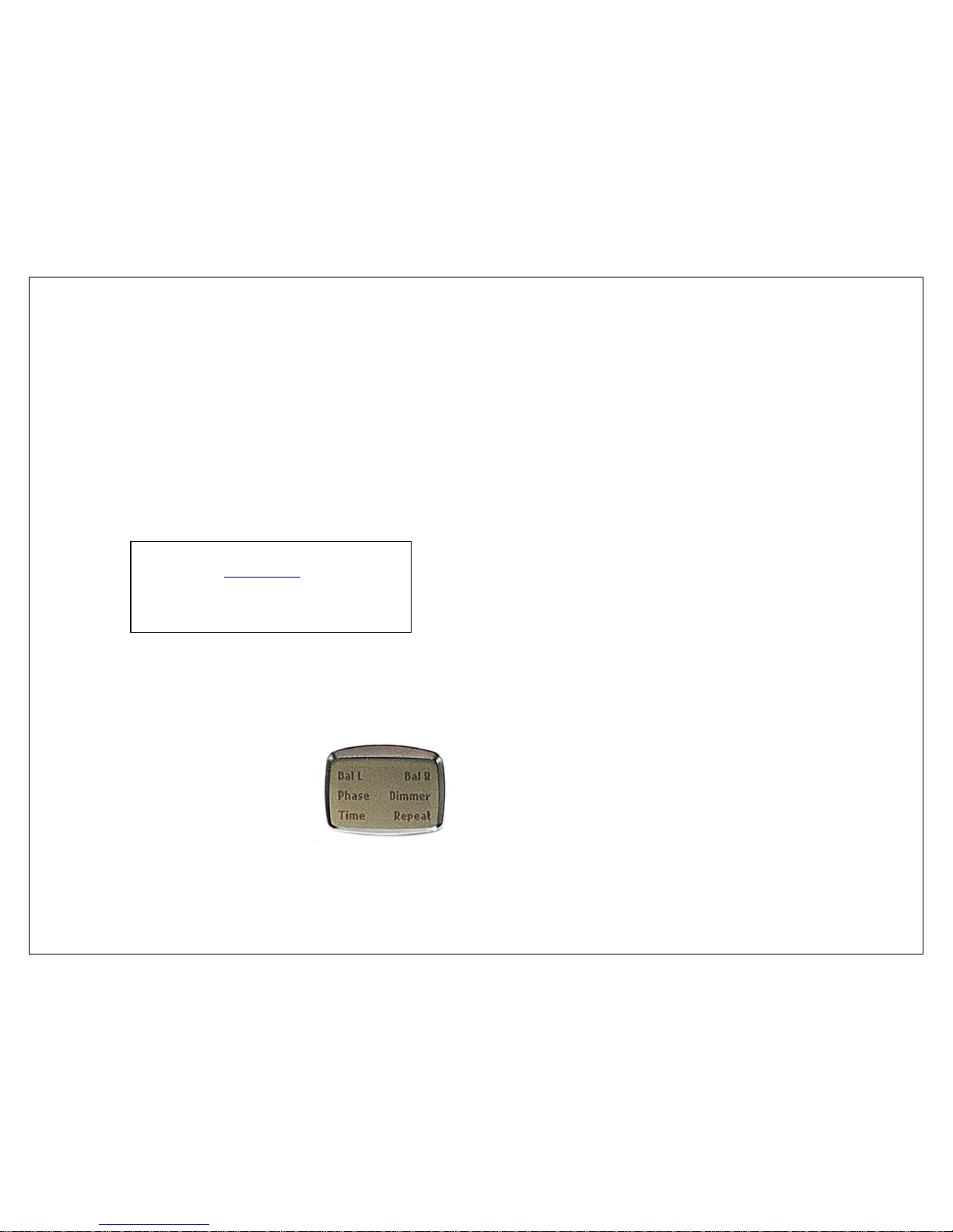
Integris CDP. The LCD display will
appear as in the picture at right.
The remote is now ready to operate the main unit. To
use the Standby feature of the Integris CDP, press the
grey OFF button. The remote’s LCD will go into a generic
default display mode. To return to use, press the red
♫
Standby On button.
Synchronization
Depending upon the initial power and standby status of
the Integris CDP, the remote and main unit could be in
opposite modes. To synchronize them, if the remote is
On and the player in Standby mode, press the main
unit’s front panel STANDBY button to bring it into its
Operate mode. If the remote is OFF and the main unit is
in Operate, press the front panel STANDBY button to put it
into Standby mode. When synchronized, the remote can
be used to engage or disengage Standby settings
correctly.
As an alternate to synchronizing by means of the front
panel button, the user may cover the IR transmitter on
the end of the remote and press whichever of the
remote’s Standby On/Off buttons as necessary to make
the remote and main unit agree.
If already properly synchronized, using the front-panel
Standby button directly will put the two devices into
opposite standby conditions. Be aware that if using the
front panel STANDBY button to put the main unit into
Standby mode, the user should then use the front panel
button again to take it out of Standby. This will ensure
that the remote and main unit are synchronized again.
Standby is the only function where this type of confusion
could occur.
Non-alkaline disposable batteries work
but will drain much faster
. Better quality
rechargeable nickel-metal-hydride
(NiMH) batteries can provide
performance comparable to alkalines.
Page 15

14
Unique Button Assignments
Nearly all Integris CDP front panel controls are duplicated
on the remote. The remote also provides direct CD track
entry and a Mute option.
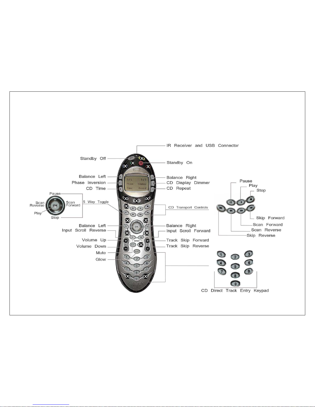
The graphic of the R-676 on the following page illustrates
the function of all buttons related to operation of the
Integris CDP.
Non-Usable Buttons: On the R-676 graphic, a number of
buttons have been over-marked with X. These buttons
are not assigned to any commands for the Integris CDP.
They are available for use with other devices the user
may load into the remote.
CD Transport Controls: For convenience, the CD transport
controls occupy two areas.
• On the two rows of buttons above the 5-way
toggle. These are labeled with the standard
transport playback symbols.
• On the 5-way toggle and on the CH +/- rocker
button. The 5-way toggle is configured exactly
like the 5-button CD control array on the front
panel. The CH +/- button provides convenient
track skip control.
Preamp Input Selection: The buttons labeled A and B,
having - INPUT + silk-screened below them, provide
continuous scrolling through the 11 available Inputs.
Direct CD Track Entry: The numeric keypad provides
direct track entry from 1-99 without requiring the use of
extra keys. The system logic provides instant response to
most entries. Where two-digit track entry is required, the
system logic will allow one second for the user to enter
the second digit.
Direct track entry may be used from Stop mode or during
playback – Play mode will be automatic. In Pause
mode, direct track entry will result in the transport cueing
up to the requested track but staying in Pause mode.
Track Entry Examples
• On a disc with 30 tracks, to play track 23, the user
will press 2 and will have another second to press
3, after which the transport will immediately
respond by going to track 23.
• To hear track 2 on that same disc, the user will
press 2. The system logic will wait one second for
another digit entry. As a second digit is not
received, the transport will automatically proceed
to track 2. Note: it is unnecessary to enter 0 as a
first digit – it will be ignored.
• If the user selects track 4 from that same disc, the
system will respond without delay because it
knows there are no 2-digit track entries that can
begin with a 4 on that disc.
Page 16
15
Aurum Acoustics R676 Remote – Keys and Features
Page 17
16
MENU ─ Optional User Settings
The Integris CDP has several programmable features that
can provide extra utility and value to many users. The
product is fully useable without ever entering into the
MENU setup; however, these user-customizable features
can increase user-satisfaction.
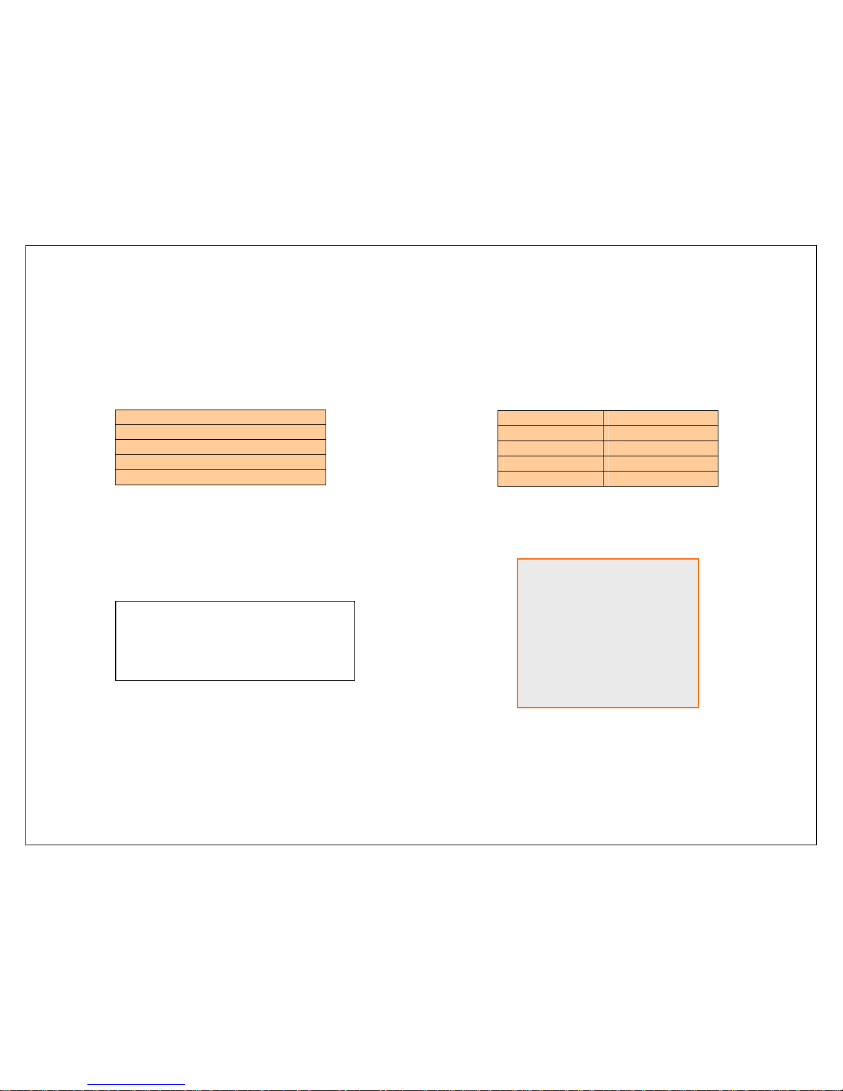
MENU of optional setup areas
Input Name Setting
Analog Level Trim
Volume Control Bypass
Preferences Save and Reset
The User Setting Menus are explained in the following
pages through the use of step-by-step examples
accompanied by graphics of the VFD.
How to Navigate the User-Interface
The MENU button is located on the front-panel within the
preamp’s volume and balance control cluster. This 5button array is used for all navigation and control within
the MENU as follows:
VOL + ▲ UP
VOL ─ ▼ DOWN
MENU ● ENTER
BAL L ◄ LEFT
BAL R ► RIGHT
5-Button Menu User-Interface
The Menu system is not accessible via the remote control.
The MENU system times out after 30
seconds of inactivity and returns to
normal operations. Any partially
changed settings may be lost if this
dela
y p
eriod is exceeded.
UP
▲
ENTER
LEFT ◄ ● ► RIGHT
▼
DOWN
Page 18
17
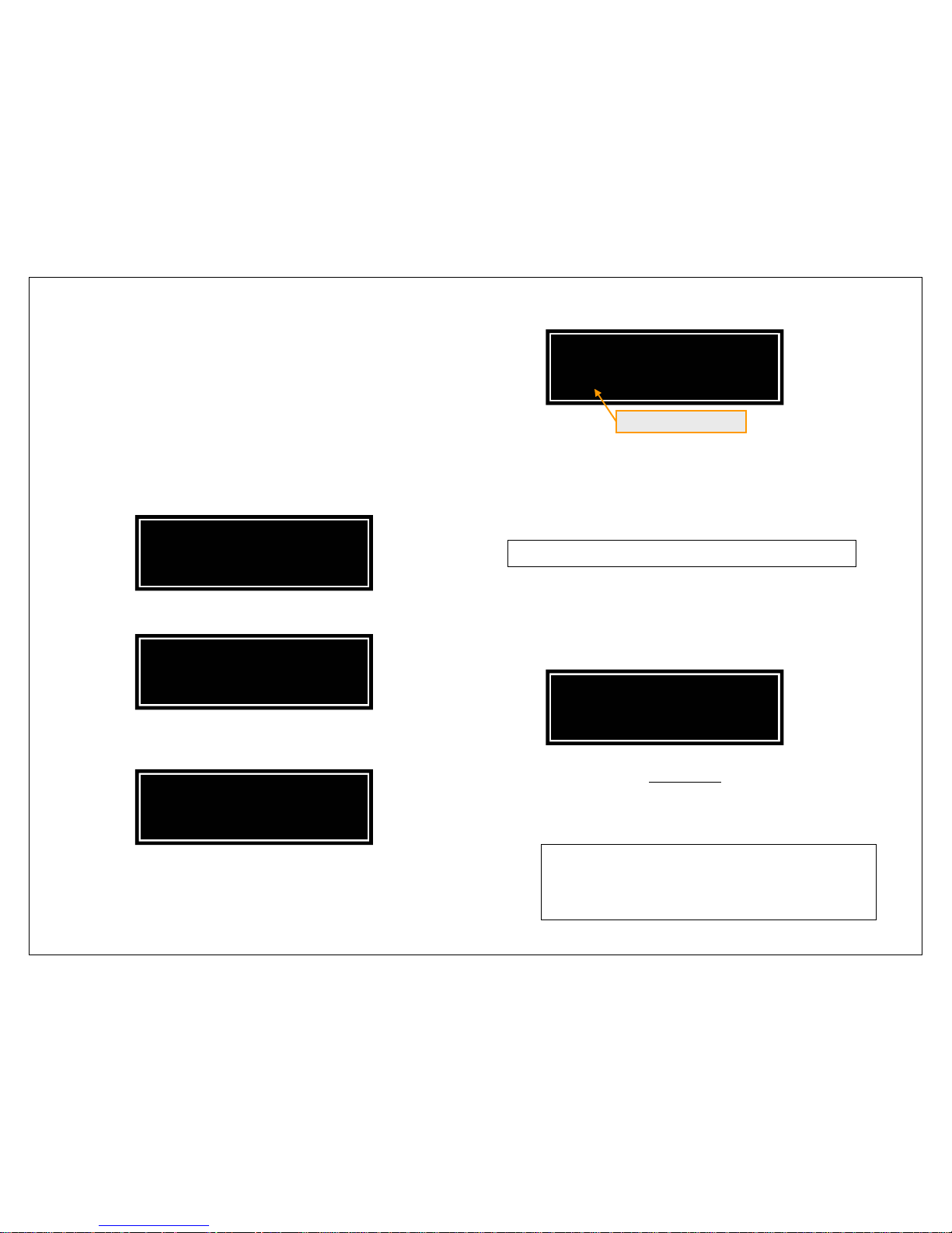
Setting Input Names
The default names of the Inputs match the rear panel
markings. Users may prefer to personalize the names to
more closely match their input device by creating a new
name up to 12 characters in length. In the following
example the UNBALANCED 2 input name is changed to
FM TUNER.
1. Press the ●MENU button to access the Menu structure.
Beyond this point the same button will be referred to as
●ENTER.
2. To access NAMES menu, Press the ●ENTER button.
3. The first Input on the list is CD. Press the ►RIGHT button
twice to scroll to UNBALANCED 2.
4. At the correct Input selection, press ●ENTER to
proceed to edit the Input name.
5. Each character may be changed by scrolling through
the available character list using the ▲UP and ▼DOWN
Buttons. When the desired character is reached, move
the cursor using the ◄LEFT or ►RIGHT Buttons to change
another.
Available characters:
█
ABCDEFGHIJKLMNOPQRSTUVWXYZ0123456789/
(The first item on the list is a blank space)
For this example, place two blank spaces at the
beginning – this will align the new name to the center of
the available 12 character display area. Carry on with
the selection of F-M-blank-T-U-N-E-R-blank-blank.
6. Press ●ENTER to save temporarily
. The display will return
to that of Step 3. The user may go on to edit other Input
names or exit the menu system by pressing ▲UP to retreat
through the menu structure.
This is a soft-save. The settings will no longer exist
if mains power is switched off or lost. To preserve
the settings to hard memory, use the saving
procedure in the PREFERENCES settings.
EDIT UNBALANCED 2
> FM TUNER █<
EDIT UNBALANCED 2
>█NBALANCED 2<
INPUT NAMES
< UNBALANCED 2 >
INPUT NAMES
CD >
SETUP MENU
NAMES >
Page 19

18
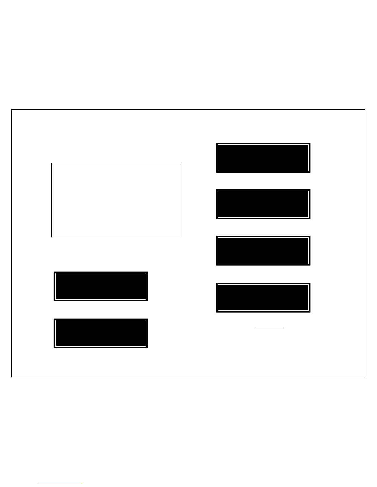
Setting Analog Input Levels
Each analog input can be adjusted by +/- 12dB in
0. 5dB increments. This enables closer matching of levels
among Input devices so there is less volume control
disparity among Inputs.
In this example, we are giving the FM TUNER (on
UNBALANCED 2) a boost of +6dB to compensate for a
source with low output.
1. Press ●MENU to enter the menu structure.
2. Scroll ►RIGHT to ANALOG LEVELS.
3. Press ●ENTER to access the ANALOG LEVELS menu.
4. Scroll ►RIGHT to the appropriate input. Notice that the
name change is retained from the previous example.
5. Press ●ENTER to proceed to adjust the level of this Input.
6. Use ◄LEFT or ►RIGHT to adjust the levels. In the
example, move ►RIGHT until +6.0dB is achieved.
7. Press ●ENTER to save temporarily
. The display screen will
return to that of Step 4 above. The user may then go on to
adjust other Analog Input levels or exit the menu system by
pressing ▲UP to retreat through the menu structure.
FM TUNER LEVEL
<– +6.0dB +>
FM TUNER LEVEL
<– +0.0dB +>
ANALOG LEVELS
< FM TUNER >
ANALOG LEVELS
UNBALANCED 1 >
SETUP MENU
< ANALOG LEVELS >
SETUP MENU
NAMES >
Page 20
19
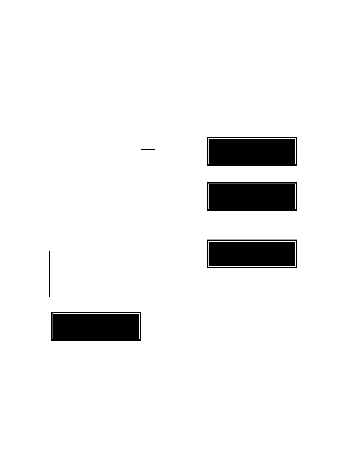
Volume Control Bypass
The Volume Bypass option is available on all Analog Inputs.
It is intended for use where an Input device’s volume
control is preferred or recommended.
In this example, UNBALANCED 3 will be set to VOLUME
BYPASS for fixed level operation.
1. Press ●MENU to enter the menu structure.
2. Scroll ►RIGHT to navigate to VOLUME BYPASS.
3. Press ●ENTER to access the VOLUME BYPASS menu.
4. Scroll ►RIGHT to the appropriate input.
5. Press ●ENTER to access the bypass toggle.
6. Press ►RIGHT to change the setting.
7. Press ●ENTER to save temporarily
and leave the volume
bypass toggle. The display screen will return to that of Step
4 above. The user may then go on to adjust other Input
Volume Bypasses or exit the menu system by pressing ▲UP
to retreat through the menu structure.
The most common application for the Volume
Bypass is within A/V systems utilizing a Home
Theatre Processor (HTP). A user seeking to
maximize the fidelity of CD playback should
connect the Integris CDP directly to the power
amplifier for the L/R loudspeaker pair. The L/R
analog signals from the HTP would be
connected to an Analog Input of the Integris
CDP set to Volume Bypass. The Analog Input
Level trim setting is still available as a
simultaneous o
p
tion if needed.
UNBALANCED 3 BYPASS
< VOLUME BYPASSED
UNBALANCED 3 BYPASS
OFF >
VOLUME BYPASS
< UNBALANCED 3 >
VOLUME BYPASS
UNBALANCED 1 >
SETUP MENU
< VOLUME BYPASS >
SETUP MENU
NAMES >
Page 21
20
Saving and Resetting Preferences
User settings are soft-saved unless the Preference Save
routine to hard-save data is used. Soft-save settings are
stored in a volatile memory that will be lost if mains
power is turned off or fails.
The Standby feature will not result in loss of soft-save
settings. This includes Volume, Balance, and Input
settings in addition to the user-settings accessed within
the Menu system.
Saving user settings permanently:
Use the PREFERENCES SAVE routine to permanently store a
new configuration that is to the user’s liking.
Saving can be done incrementally. This is recommended
to avoid an accidental loss of all user data.
1. Press ●MENU to enter the menu structure.
2. Scroll ►RIGHT to navigate to PREFERENCES.
3. Press ●ENTER to access the PREFERENCES menu.
4. Press ●ENTER to SAVE all current user settings. The SAVED
message screen below will appear for one second and the
Menu system will automatically be exited.
In addition to the MENU-accessed settings,
the current Input selection and the volume
and balance control settings during the
PREFERENCES SAVE will be memorized as the
new defaults to be used at mains power turn
on! The user can set these to meet their
p
references.
PREFERENCES
SAVED
PREFERENCES
SAVE >
SETUP MENU
< PREFERENCES
SETUP MENU
NAMES >
Page 22

21
Preferences Reset:
PREFERENCES RESET returns settings to those previously
saved by the PREFERENCES SAVE operation above. Any
soft-save settings will be discarded and the last hard-save
settings will be restored.
RESET can be chosen by first following Steps 1-3 above to
enter the PREFERENCES menu.
4. Scroll ►RIGHT to RESET.
5. Press ●ENTER to access the RESET function.
6. Press ●ENTER to CONFIRM the RESET to previously saved
user settings. The Menu will automatically be exited.
Restore Factory Settings:
This option restores all settings to the factory defaults. It
wipes out all previous soft-save and hard-save settings.
This option may be helpful if the product is set up in a new
or different system with many changes in set-up.
Factory Settings can be chosen by first following Steps 1-3
above to enter the PREFERENCES menu.
4. Scroll ►RIGHT to FACTORY SETTINGS.
5. Press ●ENTER to proceed.
6. Press ●ENTER again to confirm when prompted to restore
the default FACTORY SETTINGS.
7. At this point, the factory settings are installed as a softsave. To hard-save, repeat the PREFERENCES SAVE routine
to permanently retain the default settings.
FACTORY SETTINGS
PLEASE CONFIRM
PREFERENCES
< FACTORY SETTINGS
RESET PREFERENCES
PLEASE CONFIRM
PREFERENCES
< RESET >
Page 23

22
Specifications
Dimensions and Weight
Front panel width 483mm 19.0”
Main body width 458mm 18.0”
Depth 355mm 14.0”
Overall Height 112mm 4.4”
Net weight 13.2kg 29 lbs
Shipping Weight 14.5kg 32 lbs
AC Power Requirement
Frequency/phase 50/60Hz single phase
Voltage 100V / 120V / 230V
Consumption 20 watts
Input/Output Impedance
Inputs:
Analog unbalanced 25.0kΩ
Analog balanced 48.0kΩ each phase
Digital SPDIF / BNC 75Ω
Digital AES/EBU 110Ω
Outputs:
Analog unbalanced 75Ω
Analog balanced 75Ω each phase
Digital SPDIF 75Ω
Maximum Analog Signal Levels
Outputs driven from internal CD – for discs encoded to
0dBfs and volume control set to +20dBu:
Unbalanced 7.75 Vrms
Balanced 15.5 Vrms
Outputs will never clip
Outputs driven from external source into analog Inputs:
Unbalanced 8.5 Vrms
Balanced 17.0 Vrms
Maximum before clipping
Nominal Analog Input Gain 12dB
A
dditional ± 12dB trim available in user-settings
Inputs before overload – maximum analog signal level
accepted from an external source:
Unbalanced 5.0 Vrms
Balanced 10.0 Vrms
Page 24

23
Warranty
Aurum Acoustics warrants the Integris CDP to be free of
manufacturing defects in material and workmanship for
a period of five years except for the transport
mechanism and remote control. The warranty period for
the transport mechanism and remote control is two
years.
Warranty coverage is effective from the date-ofpurchase from an authorized Aurum Acoustics retailer.
The original dated invoice is required as proof of
purchase and ownership to obtain warranty service.
Warranty service is available only to the original owner. It
is non-transferable.
Prior to shipping any product for return, the owner must
contact Aurum Acoustics or its authorized reseller to
determine the best course of action. Aurum Acoustics
shall resolve any warranty or repair claim as efficiently as
possible. Only authorized returns, in their original
packaging, sent freight prepaid, will be accepted.
Aurum Acoustics reserves the right to inspect, or have its
authorized reseller inspect, any product that is the
subject of a warranty claim prior to repairing or replacing
it. Final determination of warranty coverage lies solely
with Aurum Acoustics.
The product must not have been altered or improperly
serviced. The serial number must not be altered or
removed. Do not submit the product to any unauthorized
service personnel. Any of the above may result in partial or
complete warranty refusal.
Out-of-warranty or non-warranty repairs will be billed for
materials, labour, return freight and insurance as required.
For warranty-approved claims, Aurum Acoustics will bear
these costs.
Aurum Acoustics does not assume any obligation to retrofit
any subsequent design changes into its previously
manufactured products.
Aurum Acoustics does not assume any obligation for any
incidental or consequential damages as a result of any
defect or warranty claim, whether express or implied.
This warranty is valid only in Canada and
the United States. Distributors and
retailers outside Canada and the United
States are responsible for administering
their own warrant
y p
olicy.
 Loading...