

Page 1
INSTALLATION,
OPERATION AND
MAINTENANCE
INSTRUCTIONS
FOR
MODEL 441
HORIZONTAL SPLIT CASE
&
MODEL 491
SPLIT CASE FIRE PUMP
Page 2

TABLE OF CONTENTS PAGE i
TOPIC PAGE
PUMP IDENTIFICATION . . . . . . . . . . . . . . . . . . . . . . . . . . . . . . . . . . . . . . . 1
STORAGE OF PUMPS . . . . . . . . . . . . . . . . . . . . . . . . . . . . . . . . . . . . . . . 2
CAUTION NOTES . . . . . . . . . . . . . . . . . . . . . . . . . . . . . . . . . . . . . . . . . . 2
INTRODUCTION. . . . . . . . . . . . . . . . . . . . . . . . . . . . . . . . . . . . . . . . . . . . 3
INSTALLATION
1. General . . . . . . . . . . . . . . . . . . . . . . . . . . . . . . . . . . . . . . . . . . . . 3
2. Net Positive Suction Head (NPSH) . . . . . . . . . . . . . . . . . . . . . . . . . . . . . 3
3. Minimum Submergence of Suction Pipe and Pit Design . . . . . . . . . . . . . . . . . . 4
4. Location and Handling . . . . . . . . . . . . . . . . . . . . . . . . . . . . . . . . . . . . 4
5. Foundation . . . . . . . . . . . . . . . . . . . . . . . . . . . . . . . . . . . . . . . . . . 4
6. Leveling of Unit . . . . . . . . . . . . . . . . . . . . . . . . . . . . . . . . . . . . . . . . 4
7. Grouting . . . . . . . . . . . . . . . . . . . . . . . . . . . . . . . . . . . . . . . . . . . 5
8. Piping . . . . . . . . . . . . . . . . . . . . . . . . . . . . . . . . . . . . . . . . . . . . . 5
9. Auxiliary Piping Connections and Gauges . . . . . . . . . . . . . . . . . . . . . . . . . 5
10. Constant Level Oiler – Oil Lubricated Pumps . . . . . . . . . . . . . . . . . . . . . . . . 5-6
11. Final Coupling Alignment . . . . . . . . . . . . . . . . . . . . . . . . . . . . . . . . . . 6-7
12. Flexible Shaft Alignment . . . . . . . . . . . . . . . . . . . . . . . . . . . . . . . . . . 7
13. Rotation . . . . . . . . . . . . . . . . . . . . . . . . . . . . . . . . . . . . . . . . . . . . 7
14. Mechanical Seals . . . . . . . . . . . . . . . . . . . . . . . . . . . . . . . . . . . . . . . 8
OPERATION
1. Operating at Reduced Capacity . . . . . . . . . . . . . . . . . . . . . . . . . . . . . . . 9
2. Priming . . . . . . . . . . . . . . . . . . . . . . . . . . . . . . . . . . . . . . . . . . . . 9
3. Starting the Pump . . . . . . . . . . . . . . . . . . . . . . . . . . . . . . . . . . . . . . 10
4. Bearing Operating Temperature . . . . . . . . . . . . . . . . . . . . . . . . . . . . . . . 10
5. Troubleshooting Operating Problems . . . . . . . . . . . . . . . . . . . . . . . . . . . . 10
MAINTENANCE
1. Maintenance History . . . . . . . . . . . . . . . . . . . . . . . . . . . . . . . . . . . . . 11
2. Inspections and Preventive Maintenance Requirements . . . . . . . . . . . . . . . . . 12
3. Bearing Lubrication
Grease-Lubricated Bearings . . . . . . . . . . . . . . . . . . . . . . . . . . . . . . . . 12
Oil-Lubricated Bearings . . . . . . . . . . . . . . . . . . . . . . . . . . . . . . . . . . . 12-13
4. Packing Box . . . . . . . . . . . . . . . . . . . . . . . . . . . . . . . . . . . . . . . . . 13
5. Packing Replacement . . . . . . . . . . . . . . . . . . . . . . . . . . . . . . . . . . . . . 13-14
6. Pump Disassembly . . . . . . . . . . . . . . . . . . . . . . . . . . . . . . . . . . . . . . 14-15
7. Pump Assembly . . . . . . . . . . . . . . . . . . . . . . . . . . . . . . . . . . . . . . . . 16-18
REPAIR PARTS . . . . . . . . . . . . . . . . . . . . . . . . . . . . . . . . . . . . . . . . . . . . 19
RECOMMENDED SPARE PARTS. . . . . . . . . . . . . . . . . . . . . . . . . . . . . . . . . . . 19
NOTES . . . . . . . . . . . . . . . . . . . . . . . . . . . . . . . . . . . . . . . . . . . . . . . . . 20-22
CROSS-SECTIONAL DRAWINGS AND PARTS LISTS . . . . . . . . . . . . . . . . . . . . . . . 23-24
Page 3

Page 4
PUMP IDENTIFICATION PAGE 1
PUMP IDENTIFICATION
Congratulations! You are the owner of one of the finest pumps commercially available. If you give it
the proper care as outlined and recommended by this manual, it will provide you with reliable service
and long life.
441 & 491 SPLIT CASE PUMPS
Your Aurora Model 441 & 491 is a Split Case Pump, meaning the casing is split along the horizontal
centerline. This new compact design, with its shorter bearing span, has less deflection under
hydraulic load which results in less wear on the sleeves, bearings and packing. It is ideally suited for
applications such as water systems, boosters, liquid transfer, irrigation and Fire Protection Systems.
These pumps are available with a wide variety of options including mechanical seals, impeller wear
rings, oil-lubricated and water-cooled bearings. Some options may not be available on Model 491
Fire Pumps.
This manual applies to:
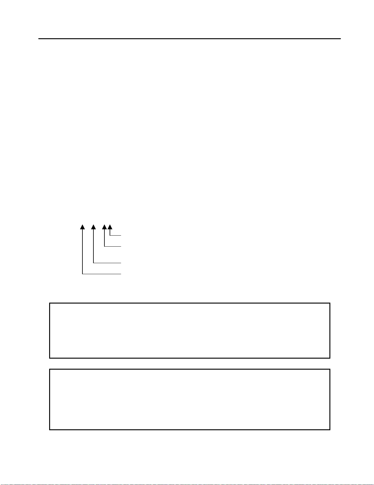
X-441-XXX Horizontal Split Case Pumps
X-491-XXX Horizontal Split Case Fire Pumps
Example: 4-491-11A
Maximum nominal impeller diameter
Carefully record all the following data from your pump nameplate. It will aid in obtaining the correct
replacement parts in the future.
FIGURE (MODEL): __________________ SERIAL NUMBER: __________________
IMPELLER DIAMETER:_______________ SIZE: _____________________________
CAPACITY: _____________ GPM ______ TOTAL HEAD ____________ FT.
RPM: __________________
HORSEPOWER: _______________ SERIAL NUMBER: _______________________
SPEED: ____________ RPM VOLTAGE: _____________________________
MANUFACTURER: _____________________ FRAME: ________________________
Hydraulic design (if applicable)
Horizontal Fire Pump
Discharge size
DRIVER
Page 5

PAGE 2 STORAGE OF PUMPS AND CAUTION NOTES
THESE INSTRUCTIONS APPLY TO THE PUMP ONLY. THEY ARE INTENDED TO BE GENERAL
AND NOT SPECIFIC. IF YOUR OPERATING CONDITIONS EVER CHANGE, ALWAYS REFER TO
THE FACTORY FOR REAPPLICATION. ALWAYS REFER TO THE MANUALS PROVIDED BY
MANUFACTURERS OF THE OTHER EQUIPMENT FOR THEIR SEPARATE INSTRUCTIONS.
CAUTION
IMPORTANT SAFETY NOTICE
THE INSTALLATION, USE AND OPERATION OF THIS TYPE OF EQUIPMENT IS AFFECTED BY
VARIOUS FEDERAL, STATE AND LOCAL LAWS AND THE REGULATIONS CONCERNING
OSHA. COMPLIANCE WITH SUCH LAWS RELATING TO PROPER INSTALLATION AND SAFE
OPERATION OF THIS TYPE OF EQUIPMENT IS THE RESPONSIBILITY OF THE EQUIPMENT
OWNER AND ALL NECESSARY STEPS SHOULD BE TAKEN BY THE OWNER TO ASSURE
COMPLIANCE WITH SUCH LAWS BEFORE OPERATING THE EQUIPMENT.
STORAGE OF PUMPS
IF THE EQUIPMENT IS NOT TO BE IMMEDIATELY INSTALLED AND OPERATED, STORE IT IN
A CLEAN, DRY, WELL-VENTILATED PLACE, FREE FROM VIBRATION, MOISTURE AND RAPID
OR WIDE VARIATIONS IN TEMPERATURE.
SPECIAL INSTRUCTIONS FOR:
OIL-LUBRICATED PUMPS: FILL THE BEARING RESERVOIRS WITH OIL. PRIOR TO
START-UP, DRAIN THE STORAGE OIL AND FILL THE RESERVOIRS WITH NEW OIL.
GREASE-LUBRICATED PUMPS: ROTATE THE SHAFT FOR SE VERAL REVOLUTIONS
CONSIDER A UNIT IN STORAGE WHEN:
1. IT HAS BEEN DELIVERED TO THE JOBSITE AND IS AWAITING INSTALLATION.
2. IT HAS BEEN INSTALLED BUT OPERATION IS DELAYED PENDING COMPLETION OF
3. THERE ARE LONG PERIODS (30 DAYS OR MORE) BETWEEN OPERATION CYCLES.
4. THE PLANT (OR DEPARTMENT) IS SHUT D OWN FOR PERIODS OF LONGER THAN 30
NOTE: STORAGE REQUIREMENTS VARY DEPENDING ON THE LENGTH OF STORAGE,
AT LEASE ONCE EVERY TWO WEEKS TO:
1. COAT THE BEARING WITH LUBRICANT.
2. RETARD OXIDATION OR CORROSION AND,
3. PREVENT POSSIBLE FALSE BRINELLING.
CONSTRUCTION.
DAYS.
THE CLIMATIC ENVIRONMENT AND THE EQUIPMENT. FOR STORAGE
PERIODS OF THREE MONTHS OR LONGER, CONTACT THE MANUFACTURER
FOR SPECIFIC INSTRUCTIONS. IMPROPER STORAGE COULD DAMAGE THE
EQUIPMENT WHICH WOULD RESULT IN NON-WARRANTY COVERED
RESTORATION REQUIREMENTS OR NON-WARRANTY COVERED PRODUCT
FAILURES.
Page 6

INTRODUCTION AND INSTALLATION PAGE 3
INTRODUCTION
This manual contains information which is the result of carefully conducted engineering and research efforts. It
is designed to supply adequate instructions for the safe and efficient installation, operation maintenance of your
pump. Failure or neglect to properly install, operate or maintain your pump may result in personal injury,
property damage or unnecessary damage to the pump.
Variations exist in both the equipment used with these pumps and the particular installation of the pump and
driver. Therefore, specific operating instructions are not within the scope of this manual. The manual contains
general rules for installation, operation and maintenance of the pump.
Observe all caution or danger tags attached to the pump or included in this manual.
INSTALLATION
1. GENERAL
CAUTION: CAREFULLY READ ALL SECTIONS OF THIS MANUALAND ALL OTHER
INSTRUCTION MANUALS PROVIDED BY MANUFACTURERS OF OTHER
Upon receipt of the shipment, unpack and inspect the pump and driver assembli es and individual parts to
ensure that none are missing or damaged. Carefully inspect al boxes and packing material for loose parts
before discarding them. Report immediately to the transportation company involved, and to the factory, any
missing parts or damage incurred during shipment, and file your “damaged and/or lost-in-shipment” cl aim with
the carrier.
Horizontal pump and driver assemblies mounted on a common base are accurately aligned at the factory.
However, alignment may be disturbed in transit or during installation. It must be checked after the unit is
leveled on its foundation, after the grouting has set and the foundation bolts are tightened, and after the piping
is completed.
When the pump and driver are mounted on separate base structures, the pump should be leveled and aligned
first, then the driver leveled and aligned with the pump. With separate bases, a flexible shaft between the pump
and driver must be used.
2. NET POSITIVE SUCTION HEAD (NPSH)
NPSH can be defined as the head (energy) that causes liquid to flow through the suction pipe and enter the eye
of the impeller.
NPSH is expressed in two values: (1) NPSH required (NPSHR) and (2) NPSH available (NPSHA). It is essential
that NPSH
NPSHR is a function of the pump design and therefore varies with the model, size, capacity and speed of the
pump. The value for your pump can be obtained from your pump performance curve or from the factory.
A. When the source of the liquid is above the pump:
NPSH
B. When the source of the liquid is below the pump:
NPSH
EQUIPMENT SUPPLIED WITH THIS PUMP.
be always greater than NPSHR to prevent cavitation, vibration, wear and unstable operation.
A
= barometric pressure (feet) + static suction head (feet) – friction losses in suction piping
A
(feet) – vapor pressure of liquid (feet)
= barometric pressure (feet) - static suction lift (feet) – friction losses in suction piping (feet)
A
– vapor pressure of liquid (feet)
Page 7
PAGE 4 INSTALLATION (continued)
3. MINIMUM SUBMERGENCE OF SICTION PIPE AND PIT DESIGN
For installations where the pump draws fluid from a sump, the hydraulic characteristics of the pump, the suction
inlet submergence and NPSH must be considered. Generally, it is required that an evenly distributed flow of
non-aerated water be supplied to the suction bell. Improper pit design or insufficient suction pipe submergence
can result in intake vortexing which reduces the pump’s performance and can result in severe damage to the
pump.
We recommend that you secure the advice of a qualified Consulting Engineer for the analysis of the suction pit.
Significant engineering data on design is provided in the Hydraulic Institute Standards.
4. LOCATION AND HAN DL ING
The pump should be located as near the fluid as possible so a short direct suction pipe can be used to keep
suction losses at a minimum. If possible, locate the pump so the fluid will flow to the suction opening by gravity.
The discharge piping should be direct and with as few elbows and fittings as possible. The total net positive
suction head available (NPSH
than the net positive suction head required (NPSH
), which includes suction lift and pipe friction losses, must be equal to or greater
A
) by the pump.
R
The pump and driver should be located in an area that will permit periodic inspection and maintenance. Head
room and access should be provided and all units should be installed in a dry location with adequate drainage.
WARNING: DO NOT LIFT THE COMPLETE UNIT BY THE DRIVER OR PUMP SHAFTS OR EYE BOLTS.
To lift a horizontal mounted unit, a chain or suitable lifting device should be attached to each corner of the unit
base. The driver by itself may be lifted using the proper eyebolts provided by the manufacturer, but these
should not be used to lift the entire assembled unit.
5. FOUNDATION
The foundation should have a level surface and have sufficient mass to prevent vibration and form a pe rmanent
rigid support for the unit. The most satisfactory foundations are concrete with anchor bolts of adequate size
embedded in the foundation in pipe sleeves with an inside diameter 2½ times larger than the bolt diameter.
This will allow final accurate positioning of the unit.
6. LEVELING OF THE UNIT
Lower the unit onto the foundation, positioning it so the anchor bolts are aligned with the center of the mounting
holes in the base. On all units, always disconnect the coupling halves and never reconnect them until all the
alignment operations are complete.
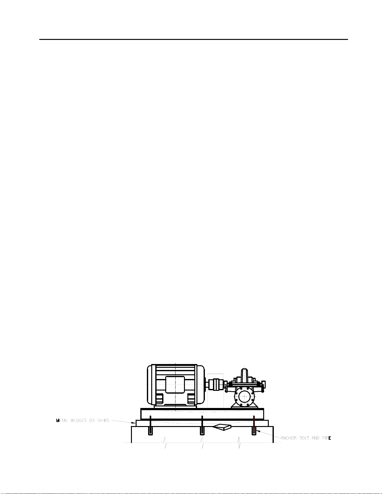
The base should be supported on metal shims or metal wedges placed directly under the part of the base
carrying the greatest weight, and spaced close enough to give uniform support and stability (see Figure 1).
Adjust the metal shims or wedges until the shafts of the pump and driver are level. Alignment adjustments can
be accomplished by adjusting the supports under the base. When proper alignment is obtained, tighten the
foundation bolts snugly, but not too firmly, and recheck the alignment before grouting.
Figure 1
BASEPLATE INSTALLATION
Page 8
INSTALLATION (continued) PAGE 5
7. GROUTING
When the alignment is correct, the unit should be grouted using high grade non-shrinking gro ut. The entire
base should be filled with grout. Be sure to fill all gaps and voids. Allow the grout to fully cure before firmly
tightening the foundation bolts. Then recheck the alignment before connecting the piping.
8. PIPING
CAUTION: ALL PIPING CONNECTIONS MUST BE MADE WITH THE PIPING IN A FREE
SUPPORTED STATE, AND WITHOUT THE NEED TO APPLY VERTICAL OR
SIDE PRESSURE TO OBTAIN ALIGNMENT OF THE PIPING WITH THE
CAUTION: AFTER ALL THE PIPING IS CONNECTED, THE PUMP AND DRIVER
All piping should be independently supported near the pump so that pipe strain will not be transmitted to the
pump casing. The suction and discharge piping should be one or two size s larger than the pump flange sizes,
especially where the piping is of considerable length. Any flexible joints installed in the piping must be equipped
with tension rods to absorb piping axial thrust. Care must be exercised in arranging elbows so as not to
generate vortexing in the pump inlet.
The suction pipe must be air tight and sloped upward to the pump flange to avoid air pockets which will impair
satisfactory pump operation. The discharge pipe should be as direct as possible with a minimum of valves to
reduce pipe friction losses.
A check valve and closing valve should be installed in the pump discharge line and a closing valve in the
suction line. The check valve, between the pump and the closing valve, protects the pump from water ham mer
and prevents reverse rotation in the event of power failure. The closing valves are used in priming, starting and
when the pump is shut down. The pump must never be throttled by the use of a valve in the suction line.
9. AUXILIARY PIPING CONNECTIONS AND GAUGES
In addition to the primary piping connections, your pump may require mechanical seal and seal water filter
connections, connections to the lantern ring (see the “Packing Box” and “Mechanical Seal” sections of this
manual), stuffing box drain, discharge and suction flange gauges, casing relief valve drain or baseplate drain
connections. All these lines and gauges should now be installed.
10. CONSTANT LEVEL OILERS
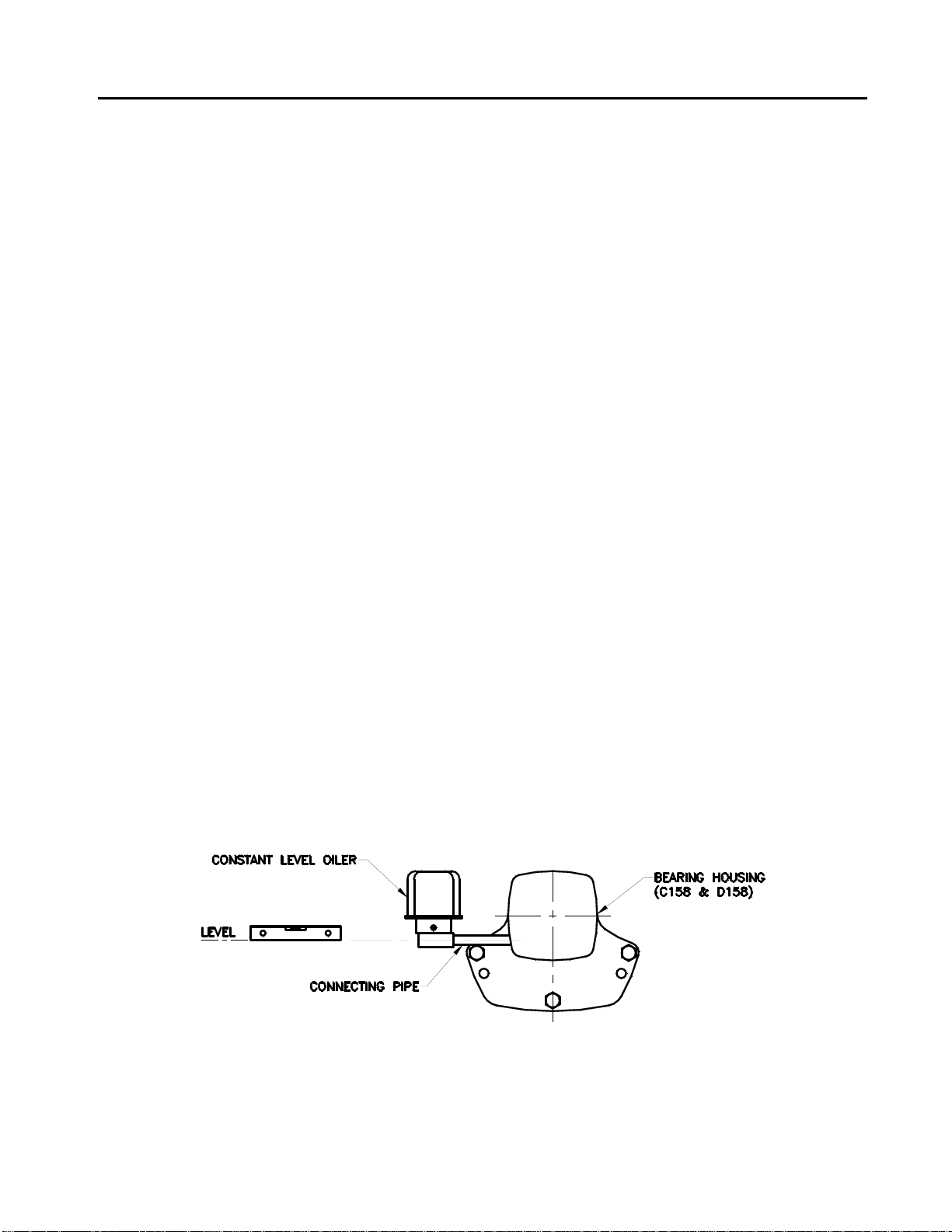
If your pump has oil-lubricated bearings, it will be equipped with constant level oilers which will be shipped loose
to prevent damage in shipment. The oilers must be installed in the tapped holes in the side of the beating
housings. To provide proper lubrication, the pipe connection the oiler to the bearing housing must be level (see
Figure 2).
PUMP FLANGE.
ALIGNMENT MUST BE RECHECKED.
FIGURE 2
When the oiler is level, fill the bottle and screw it onto the lower reservoir of the oiler. Allow the oil to flow into
the bearing reservoir. Several fillings of the bottle may be required before the oil level for which the oiler is set is
reached and the oil stops flowing. After filling the oil reservoir, check the oil level to make sure it is as specifi ed
in the following table (see Page 6).
Page 9
PAGE 6 INSTALLATION (continued)
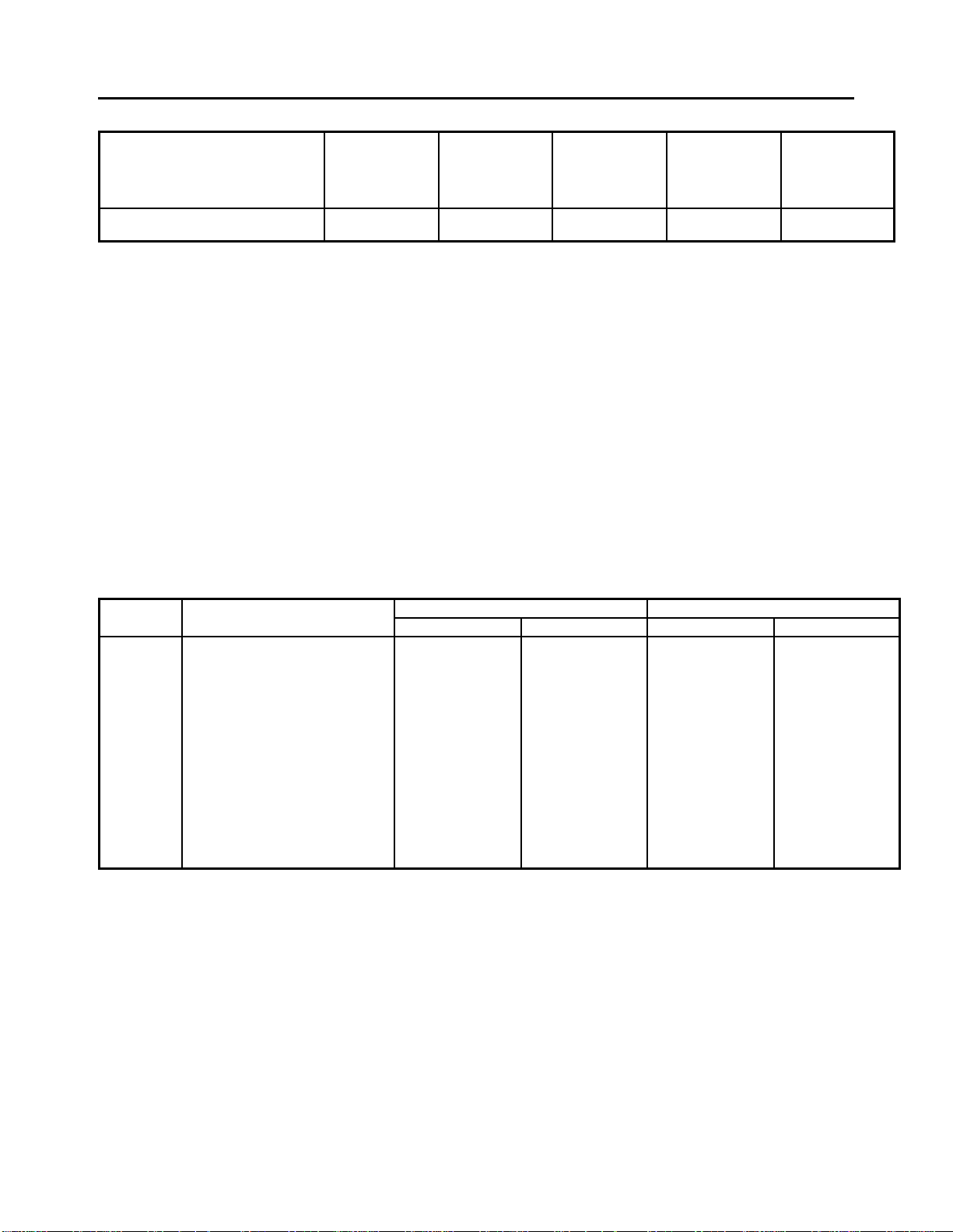
BEARING HOUSING OIL LEVEL CHART
4-441-11A/C 5-441-18A 5-441-11A
PUMP MODEL 3-441-9A/C 4-441-14C 6-441-14A/C 6-441-19A
(PUMP SIZE) 4-441-8A 5-441-14A 6-441-18C 8-441-18A
Centerline of shaft to oil level 3/4" 7/8" 1-3/16" 1-1/2" 1-13/16"
NOTE: For Fire Pumps, the Model designation changes from “441” to “491.”
Adjust the oil level, if necessary, by loosening the setscrews on the side of the dust cap, raising the bottle and
tightening the screws. Refer to the oiler manufacturer’s instructions for more specific details.
11. FINAL COUPLING ALIGNMENT
The alignment of the coupling must be carefully checked during installation and as the last step before starting
the pump. If realignment is required, the piping should be disconnected first. After aligning, reconnect the
piping in accordance with the previous instructions and again recheck the align ment.
A flexible coupling must not be used to compensate for misalignment resulting from poor installation or
temperature changes.
Aurora Pumps are supplied with several different types of commercial couplings. The following instructions
apply to units supplied with Woods couplings. If your unit has a different brand coupling, the manufacturer’s
instructions should be obtained before proceeding.
Sleeve Types E & N Type H
NOTE: FOR MAXIMUM LIFE, KEEP MISALIGNMENT VALUES AS NEAR TO ZERO AS POSSIBLE.
MAXIMUM ALLOWABLE MISALIGNMENT – WOODS COUPLINGS (Dimensions in inches)
Size Parallel Angular Parallal Angular
"G" Dimension
4 1/2 .005 .021 - 5 3/4 .007 .028 - 6 7/8 .007 .035 .005 .008
7 1 .010 .040 .006 .010
8 1-1/8 .010 .047 .007 .012
9 1-7/16 .012 .054 .008 .014
10 1-5/8 .012 .064 .010 .016
11 1-7/8 .016 .075 .011 .018
12 2-5/16 .016 .087 .012 .021
13 2-11/16 .020 .092 .015 .025
14 3-1/4 .022 .121 .017 .030
16 4-1/4 .031 .165 - -
The coupling Type is printed on the sleeve.
* Type H sleeves SHOULD NOT be used as direct replacements for EPDM or Hytrel sleeves.
A. Use a blunt screwdriver to slip the wire ring out of the groove and remove the two-piece sleeve.
Check the “G” dimension. If it is not as shown in the preceding table, loosen one flange of the
coupling and reposition it to achieve the specified “G” dimension.
NOTE: On a sleeve bearing electric motor, the armature should be at its electrical center when the “G”
dimension is measured.
B. Check parallel misalign ment by placing a straightedge across the two coupling flanges and
measuring the maximum offset at various points around the periphery of the coupling. DO NOT
ROTATE THE COUPLING. If the maximum offset exceeds the figure shown under “Parallel” in the
preceding table, realign the coupling.
2-441-8A
6-441-12A 8-441-14A 10-441-20
Page 10
INSTALLATION (continued) PAGE 7
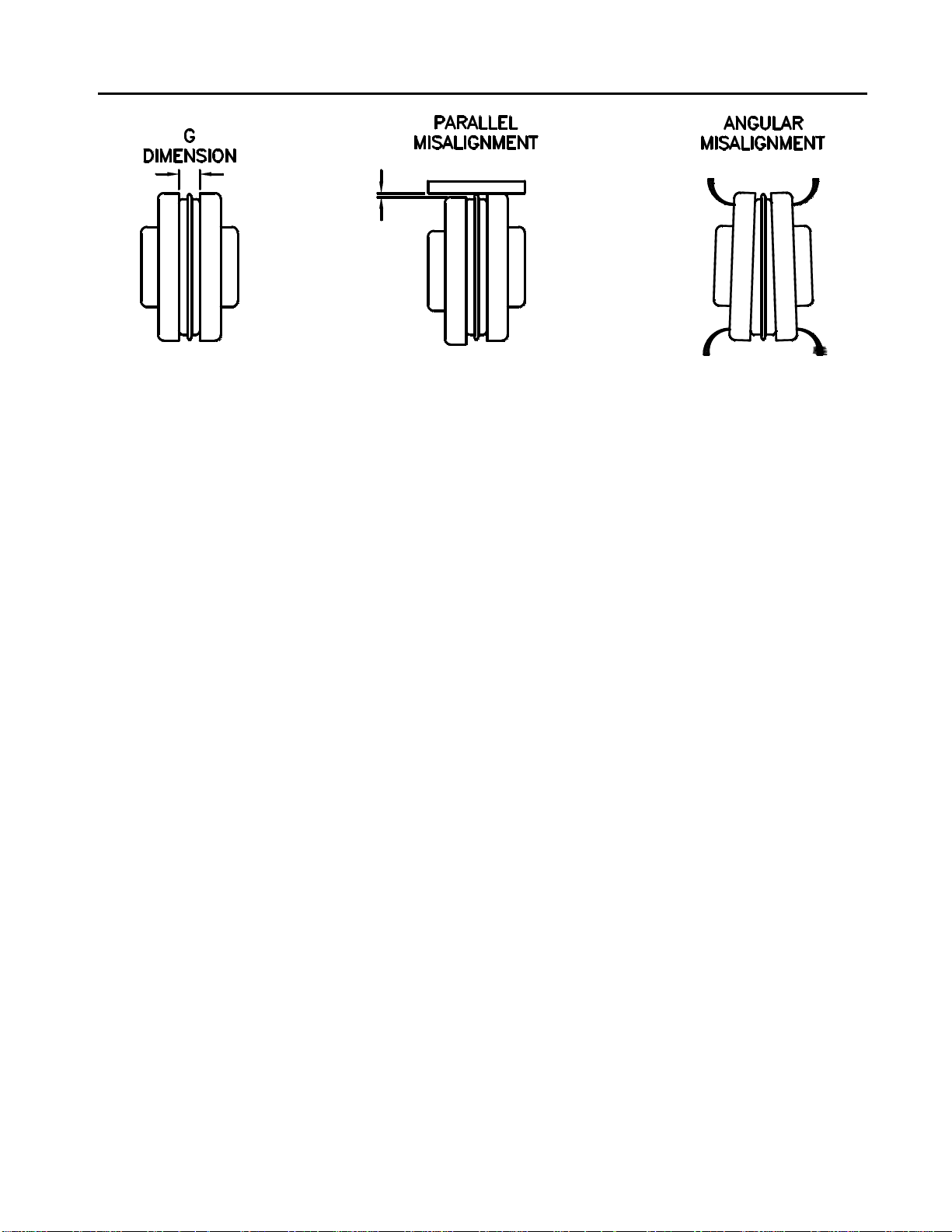
FIGURE 3
COUPLING ALIGNMENT
11. FINAL COUPLING ALIGNMENT (c ontinued)
C Check the angular alignment with a micrometer or caliper. Measure from the outside of one flange to
the outside of the other at intervals around the periphery of the coupling. Determine the maximum
and minimum dimensions. DO NOT ROTATE THE COUPLING. The difference between the
maximum and minimum dimensions should not exceed the figure shown under “Angular” in the
preceding table. If a correction is required, you must always recheck the parallel alignment.
D. If the coupling employs a two-piece sleeve with a wire ring, force the ring into its groove in the center
of the sleeve. It may be necessary to pry the ring into position with a blunt screwdriver.
WARNING: CHECK SAFETY CODES, AND ALW AYS INSTALL PROTECTIVE GUARD OR
SHIELD AS REQUIRED BY VARIOUS FEDERAL, STATE AND LOCAL LAWS AND
WARNING: COUPLING SLEEVES MAY BE THROWN FROM THE ASSEMBLY WHEN
12. FLEXIBLE SHAFTING ALIGNMENT
For installation and alignment of intermediate flexible shafting, refer to the manufacturer’s instructions.
13. ROTATION
Before connecting the coupling halves, bump start the driver to verify rotation is in the proper direction. The
correct pump rotation is indicated by a directional arrow on the pump casing.
REGULATIONS CONCERNING OSHA.
SUBJECTED TO A SEVERE SHOCK LOAD.
Page 11
PAGE 8 INSTALLATION continued)
14. MECHANICAL SEALS
CAUTION: DRY OPERATION OF THE PUMP MAY CAUSE DAMAGE TO THE MECHANICAL SEAL
AND IMPELLER.
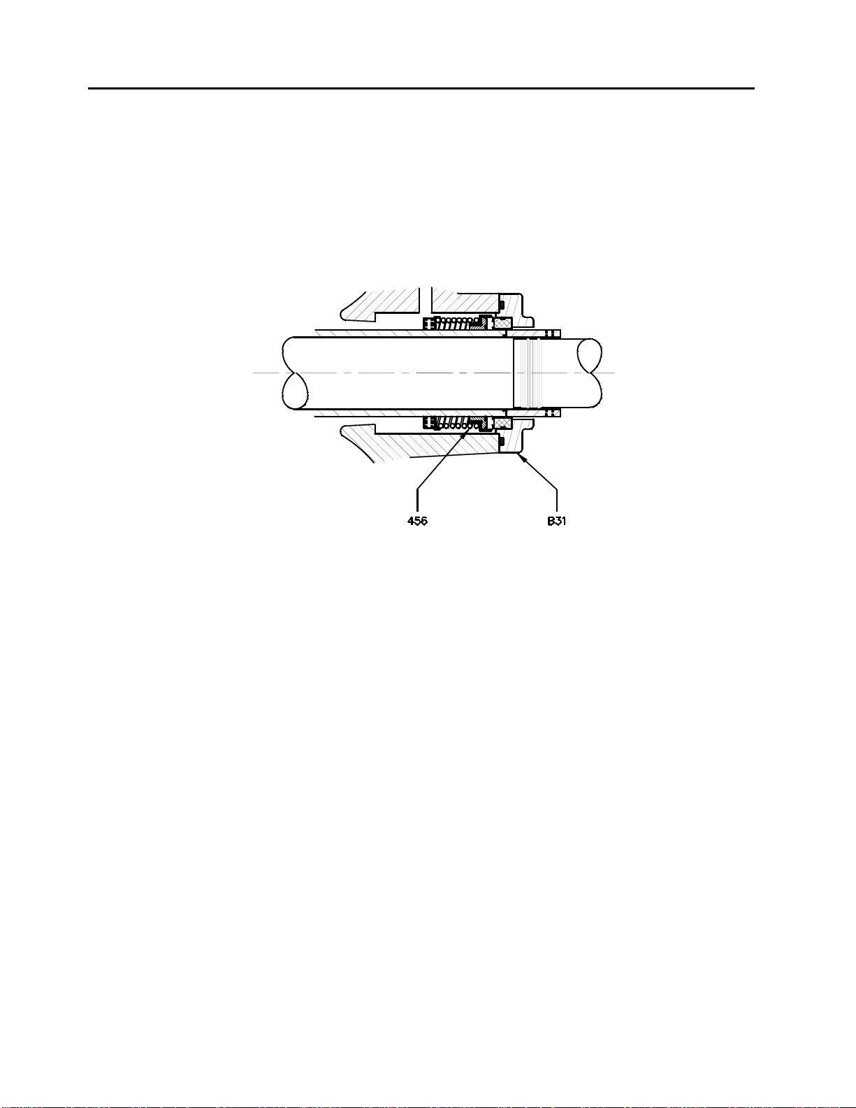
Model 441 pumps can be supplied with optional single face mechanical shaft seal s. Mechanical seals are
installed and adjusted in the factory and require no further adjustments in the field.
For further information, refer to the seal manufacturer’s instructions.
FIGURE 4
TYPICAL MECHANICAL SEAL
Page 12

OPERATION PAGE 9
Because variations exist in both the equipment used with these pumps and in the particular installation of the
pump and driver, specific operating instructions are not within the scope of this manual. However, there are
general rules and practices that apply to all pump installations and operation.
CAUTION: BEFORE STARTING OR OPERATING THE PUMP, READ THIS ENTIRE MANUAL,
A. BEFORE STARTING THE PUMP, INSTALL CLOSED GUARDS AROUND THE COUPLING.
B. BEFORE STARTING THE PUMP, ROTATE THE UNIT OR ASSEMBLY BY HAND TO ASSURE ALL
C. OBSERVE ALL CAUTION AND DANGER TAGS ATTACHED TO THE EQUIPMENT.
D. NEVER RUN THE PUMP DRY AS THE CLOSE RUNNING FITS WITHIN THE PUMP ARE WATER
E. BEFORE STARTING THE PUMP, FILL THE CASING AND SUCTION LINE WITH LIQUID. THE
F. BEFORE STARTING A PACKED BOX PUMP, ADJUST THE PACKING GLAND SO THERE IS
G. IF EXCESSIVE VIBRATION OR NOISE OCCURS DURING OPERATION, SHUT THE PUMP DOWN
1. OPERATING AT REDUCED CAPACITY
Although these pumps are applicable over a wide range of operating conditions, care should be exerci sed when
doing so, especially when the actual conditions differ from the sold-for conditions. You should always contact
your nearest Aurora Pump sales office before operating the pumps for any condition other than that for which it
was sold.
2. PRIMING
Since the pump medium is used to lubricate various internal parts, running a centrifugal pump dry can result in
extensive damage and possible seizing. It is therefore imperative that the pump be primed prior to initial startup and that prime be maintained through subsequent start-stop cycles.
The priming method is different for positive and negative suction head systems, and the following procedures
should be followed.
A. Positive Suction Head –
B. Negative Suction Head –
ESPECIALLY THE FOLLOWING INSTRUCTIONS:
MOVING PARTS ARE FREE.
LUBRICATED. RUNNING DRY MAY RESULT IN PUMP SEIZURE.
PUMP MAY BE PRIMED USING AN EJECTOR OR VACUUM PUMP.
SUFFICIENT LEAKAGE TO LUBRICATE THE PACKING AND ASSURE A COOL PACKING B OX.
(SEE MAINTENANCE INSTRUCTIONS).
AND CONSULT AN AURORA PUMP REPRESENTATIVE.
1. Open the vent on the highest point on the pump casing.
2. Open all suction valves.
3. Allow the pumped liquid to flow from the vent hole until all air bubbles are vented, then close the
vent.
4. The pump is now primed.
1. Install an ejector or vacuum pump on the vent at the highest point on the pump casing.
2. Close the discharge valve.
3. Open the suction valve.
4. Start ejector or vacuum pump.
5. Allow the liquid to flow until a continuous flow is exhausted from the ejector, then close the valve to
the vent.
6. The pump is now primed.
Page 13

PAGE 10
OPERATION (continued)
3. STARTING THE PUMP
A. After the pump is primed, and with the discharge valve closed and the suction valve open, start the driver
according to the driver manufacturer’s instructions.
B. Open the discharge valve slowly to prevent water hammer.
C. After the pump has been started, check bearing temperatures, packing box lubrication and operation and
pump noise level for a period of several hours.
CAUTION: BEGIN THESE CHECKS IMMEDIATELY UPON STARTING THE PUMP AND MONITOR
4. BEARING OPERATING TEMPERATURE
These pumps are designed to operate over a wide ambient temperature range. The bearing temperature, when
measured at the outside surface of the bearing housing, should not exceed 190
o
F may indicate lack of lubricant, bearing overload or insipient bearing failure. If the temperature exceeds
190
this limit, the pump should be stopped and the cause investigated and corrected.
5. TROUBLESHOOTING OPERATING PROBLEMS
THEM CONTINUOUSLY FOR THE FIRST SEVERAL HOURS OF OPERATION.
o
F. Temperatures in excess of
If you have followed the installation and start-up procedures outlined in this manual, your pump should provide
reliable service and long life. However, if operating problems do occur, significant time and expense can be
saved if you use the following checklist to eliminate the most common causes of those problems.
INSUFFICIENT DISCHARGE
PRESSURE OR FLOW
1. Pump not primed.
2. Speed too slow; check driver.
3. Discharge head too high.
4. Suction lift too high.
5. Wrong direction of rotation
6. Air leaks into suction piping, packing box or
gaskets.
7. Impeller passage partially plugged.
8. Impeller damaged.
9. Impeller running clearance too large.
10. Insufficient suction line submergence.
11. Air in liquid.
12. Impeller diameter too small.
13. Insufficient Net Positive Suction Head.
LOSS OF SUCTION DURING OPERATION
1. Suction line leaks.
2. Water seal line plugged.
3. Suction lift too high.
4. Air or gases in liquid.
5. Air leaks into suction piping, packing box or
gaskets.
6. Wrong direction of rotation.
7. Insufficient suction line submergence.
EXCESSIVE POWER CONSUMPTION
1. Speed too high.
2. Head lower than rating, pumping too much liquid.
3. Specific gravity or viscosity of liquid too high.
4. Mechanical defects:
• Shaft bent
• Rotating element binds
5. Misalignment.
6. System head lower than design.
1. Misalignment between driver and pump.
2. Loose foundation bolts or defective grouting.
3. Mechanical defects:
• Shaft bent
• Rotating element binds
4. Head lower than rating; pumping too much liquid.
5. Pipe strain – improperly supported or aligned.
6. Pump running at shut-off condition.
7. Insufficient suction line submergence.
8. Air in liquid.
1. Bearings:
• Excessive grease.
• Shaft bent.
• Rotating element binds.
• Pipe strain.
• Insufficient bearing lubrication.
• Incorrect type grease
2. Packing box:
• Packing gland too tight.
• Water seal line plugged
• Air not vented out of mechanical seal.
• Flushing water not circulating for mechanical
seal.
VIBRATION OR NOISE
OVERHEATING
7. Incorrect impeller diameter.
Page 14

MAINTENANCE PAGE 11
1. MAINTENANCE HISTORY
DATE MAINTENANCE PERFORMED PARTS USED
SYMBOL
NUMBER(S)
Page 15

PAGE 12 MAINTENANCE (continued)
2. INSPECTIONS AND PREVENTIVE MAINTENANCE REQUIREMENTS
To assure satisfactory operation of the pump, daily inspections and periodic maintenance are required. We
suggest that an inspection and maintenance log be kept and that the inspector immediately report any
problems. A guide for preventive maintenance for normal applications is given below. Unusual applications,
with abnormal heat, moisture, dust, etc. may require more frequent inspections and service.
ITEM
Packing Box
Pump Alignment
Vibration
Bearings:
Grease lubricated
Oil lubricated
Adjust gland, inspect packing for
possible replacement
Check for change in alignment
Check for change in vibration
Lubricate
3. BEARING LUBRICATION
A. Grease Lubricated Bearings
Under normal operating conditions, the bearings must be lubricated after every 2000 hours of running
time, but at least once a year regardless of total operating hours.
CAUTION: ANY APPLICATION WITH ABNORMAL HEAT, MOISTURE, DUST, ETC. MAY
REQUIRE A CHANGE IN THIS SCHEDULE AND YOU SHOULD REFER TO A
LUBRICATION ENGIEER OR THE FACTORY FOR SPECIFIC INSTRUCTIONS.
CAUTION: THE GREASES RECOMMENDED IN THIS MANUAL WILL PROVIDE SATISFACTORY
LUBRICATION OVER A WIDE TEMPERATURE RANGE. THERE IS, HOWEVER, A
PRACTICAL LIMIT, AND OPERATION OF THE PUMP SHOULD BE DISCONTINUED
AND THE FACTORY CONSULTED IF THE TEMPERATURE, WHEN MEASURED ON
THE OUTSIDE OF THE BEARING HOUSING, EXCEEDS 190
RECOMMENDED GREASE: Chevron SRI grease N.L.G.I. No. 2 multi-purpose with a mineral oil
viscosity of 517 SUS at 100
Proceed as follows for bearing lubrication:
WARNING: KEEP HANDS, FINGERS, CLOTHING AND ANY TOOLS AWAY FROM THE
COUPLING. FAILURE TO DO SO COULD RESULT IN SERIOUS PERSONAL
INJURY.
1. Stop the pump and remove the pipe plug at the bottom of the bearing housing.
2. Connect a grease gun to the lubrication fitting.
3. Inject grease until it relieves at the bearing housing cover and drain hole.
4. Remove the grease gun.
5. Start the pump. NOTE: Immediately after lubrication, bearing temperatures may rise above the
normal level. Continue running the unit until bearing temperatures stabilize at the normal level.
6. Stop the unit, wipe off the relieved grease and replace the drain plug.
7. Start the unit and resume normal operation.
B. Oil Lubricated Bearings
Fill the constant level oiler and add additional oil as required. Replace the old oil with new every 2000
hours, but at least once a year. Drain the oil by removing the plug at the bottom of the bearing
housings (C158 and D158).
ACTION REQUIRED
o
F or equivalent.
FREQUENCY (HOURS OF OPERATION)
150 Hours
ANNUALLY
ANNUALLY
Every 2000 hours of operation,
but at least once a year.
As required to maintain proper oil level –
drain and replace oil every 2000 hours of
operation, but at least once a year.
o
F.
Page 16

MAINTENANCE (continued) PAGE 13
3. BEARING LUBRICATION (continued)
Check the oiler setting periodically to be sure it is correct. Refer to the following table for the correct setting.
RECOMMENDED OILS: The oil used should be non-detergent type containing rust and oxidation inhibitors,
supplied by a reputable manufacturer.
Depending on bearing/pump operating temperature, the grade and viscosity should be as follows:
Below 120
120F to 250
Above 250
4. PACKING BOX
CAUTION: DO NOT TIGHTEN THE GLAND TO STOP ALL LEAKAGE. LEAKAGE IS NECESSARY TO
ENSURE THE COOLING, FLUSHING AND LUBRICATION OF THE PACKING AN D TO
PREVENT SHAFT SLEEVE DAMAGE.
The packing boxes on Aurora Pumps are packed at he factory. All packing is subject to wear and should be
given regular inspections and, if necessary, periodic adjustments. Generally, packed box pumps require
inspection of the packing and adjustments to the glands after each 150 hours of operation.
Adjustment is made by lightly tightening the gland nuts, then loosening them so that they can be adjusted with
finger pressure to allow a small flow of liquid to lubricate the packing. If the flow of liquid has increased and
cannot be reduced by a slight tightening of the gland, add one ring of packing to the packing box and readjust
the gland. If this fails to reduce the flow, replace the packing and/or shaft sleeve.
The packing boxes may be fitted with lantern rings. When a lantern ring is furnished, the sealing chamber
should be connected to a source of clear fresh water.
5. PACKING REPLACEMENT
Use a good grade of soft, square long fiber packing, thoroughly graphited. The replacement procedure should
be as follows:
A. Stop the pump.
B. Unbolt and remove the glands away from the packing.
C. Use a packing hook to remove the worn rings of packing and lantern rings. Note the location of the
lantern rings relative to the amount of packing on each side of the lantern rings. (See sectional
drawings on pages 23 & 24.)
D. Clean the packing boxes and shaft sleeves.
E. Inspect the shaft sleeves for wear or rough finish and replace if necessary.
F. Install new packing and lantern rings.
CAUTION: STAGGER THE PACKING END JOINTS 180 AND FIRMLY SEAT THE PACKING.
G. Reinstall the glands and tighten the gland nuts.
H. Loosen the gland nuts so they can be adjusted with finger pressure to obtain correct leakage for
lubrication after start-up.
o
F – ISO Vg Grade 40-70 (SAE 20)
o
F – ISO Vg Grade 70-100 (SAE 20)
o
F – Consult the factory for a recommendation.
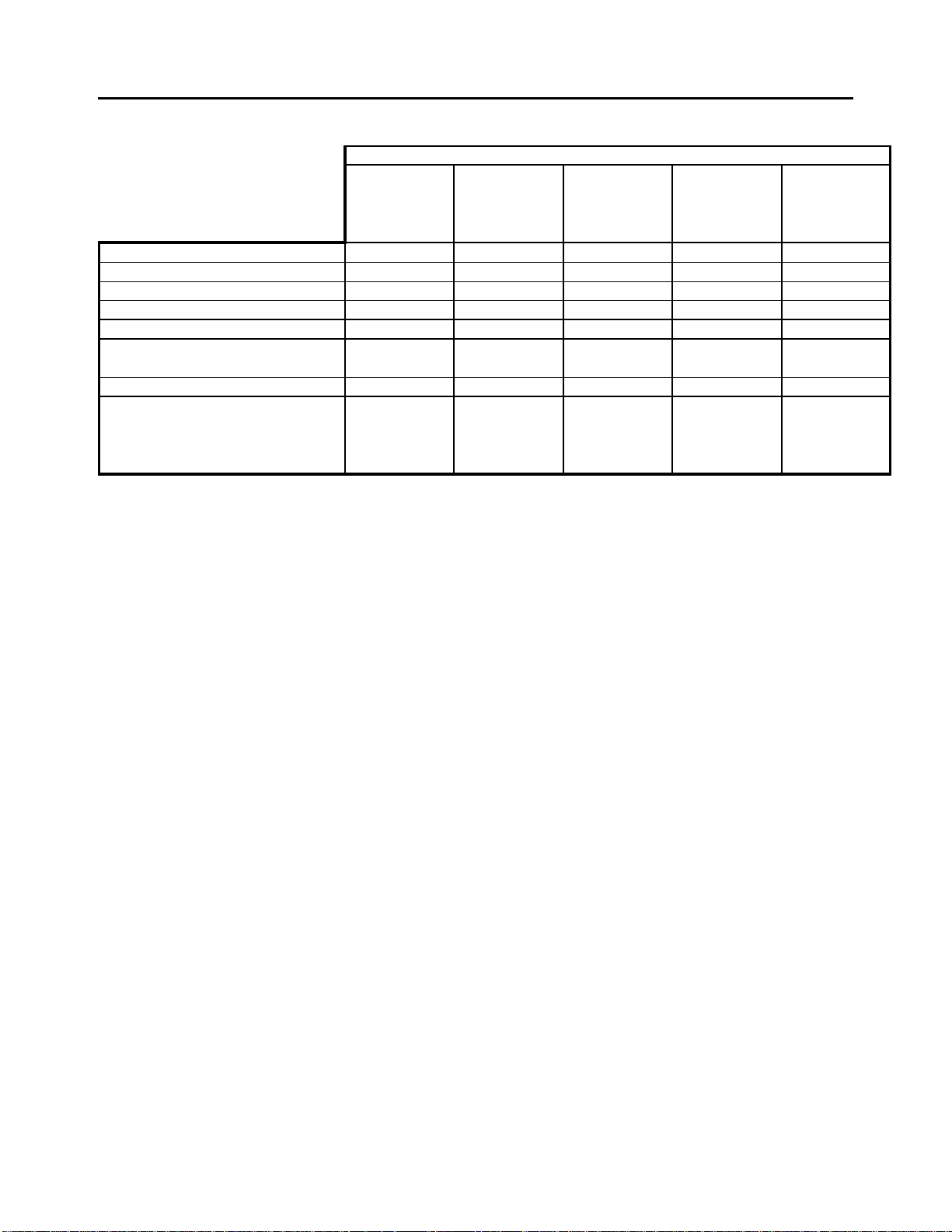
THE FOLLOWING TABLE GIVES THE PERTINENT PACKING BOX, LANTERN RING
AND PACKING DIMENSIONS (see page 14).
Page 17
PAGE 14 MAINTENANCE (continued)
)
5. PACKING REPLACEMENT (continued)
PUMP MODEL (PUMP SIZE
4-441-11A 5-441-18A
2-441-8A 3-441-9A/C 4-441-14C 6-441-14A/C 6-441-19A
4-441-8 5-441-14A 6-441-18A 10-441-20
6-441-12A 8-441-14A
PACKING BOX
Sleeve O.D. 1-5/8 2 2-1/2 3 3-1/2
Packing Box I.D. 2-7/16 2-15/16 3-9/16 4-3/16 4-13/16
Packing Box Depth 2-15/16 2-7/8 3-7/8 4-5/16 4-3/4
PACKING SIZE 3/8 3/8 1/2 9/16 5/8
Qty. of Rings per Box
(Without Lantern Ring)
Lantern Ring Width 3/4 3/4 1 1-1/8 1-1/4
PACKING ARRANGEMENT
WITH LANTERN RING
(Packing Rings-Lantern
Ring-Packing Ring)*
7 7777
2-L-3 2-L-3 2-L-3 2-L-32-L-3
* See Sectional Drawings on pages 23 & 24.
NOTE: For Fire Pumps, the Model designation changes from “441” to “491.”
6. PUMP DISASSEMBLY
CAUTION: READ THIS ENTIRE DISASSEMBLY PROCEDURE AND REFER TO THE SECTIONAL
DRAWINGS IN THIS MANUAL BEFORE PROCEEDING.
Major maintenance will require disassembly of the pump. Following are step-by-step instructions.
A. Lock out the power to the driver and close the suction and discharge valves. Drain the pump,
disconnect and remove the coupling or flexible shafting. Disconnect and remove all auxiliary piping to
the upper casing (3) and bearing housings (C158 and D158) (packing box flush line, lubricators on oil
lubricated pumps, cooling water lines on pumps with water-cooled bearings, etc.).
B. Remove the capscrews (2A) securing the upper casing half (3) to the lower half (2). Remove the gland
nuts (31B) and slide the glands (A31 or B31) off the gland studs (31A). Install jack screws in the tapped
holes in the upper casing half and use them to separate the flanges. Carefully lift the upper casing half
using the long shank eyebolts in the tapped holes in the upper casing half.
CAUTION: USE OF A CRANE OR HOIST OF ADEQUATE CAPACITY IS RECOMMENDED. THE
LIFTING HOOK SHOULD BE NO LESS THAN 3-4 FEET ABOVE THE EYE OF THE
EYEBOLTS TO AVOID BENDING OF THE BOLTS. THE USE OF THE SHORT
EYEBOLTS IS NOT RECOMMENDED SINCE THE UPPER CASING HALF WILL TEND
TO TIP WHILE BEING LIFTED, RESULTING IN POSSIBLE DAMAGE OR PERSONAL
INJURY.
C. Remove the capscrews (158B) and pins (158A) that secure the bearing housings (158) to the lower
casing. The pins may be removed using the threaded holes in the pins.
D. Lift the rotor assembly from the casing using a double rope sling.
WARNING: BE CAREFUL WHEN POSITIONING THE ROPES TO AVOID THE ROTOR SLIPPING
AND CAUSING POSSIBLE SERIOUS PERSONAL INJURY.
Page 18

MAINTENANCE (continued) PAGE 15
6. PUMP DISASSEMBLY (continued)
E. Remove the capscrews (159D) that secure the bearing housing covers (159) to the bearing housings
and remove the housings from the rotating assembly.
F. Remove the outer snap ring (345) from the outboard bearing end of the rotating assembly, and use a
wheel/bearing puller to remove the outboard (168) and inboard (163) bearings.
WARNING: TO PREVENT POSSIBLE SERIOUS PERSONAL INJURY, EXTREME CARE SHOULD
BE EXERCISED TO SELECT THE PROPER PULLER, AND APPROVED SAFETY
GLASSES SHOULD BE WORN.
CAUTION: BECAUSE OF POSSIBLE DAMAGE OR CONTAMINATION DURING REMOVAL,
BEARINGS SHOULD NOT BE REUSED AND NEW BEARINGS SHOULD ALWAYS
BE INSTALLED.
G. Remove bearing housing covers (159), water slingers (126), casin g wearing rings (16), lantern rings
(10) and packing (212). If the pump is equipped with mechanical seals (456), refer to the seal
manufacturer’s instructions.
If the pump is equipped with an oil lubrication system, remove the lip seals (158C) from the inboard and
outboard bearing housing covers and the inboard bearing housi ng.
H. Remove the shaft sleeves (A14 or B14). Depending on the pump service, shaft sleeves are supplied in
two different configurations. The removal procedure for each configuration differs:
Sleeves Affixed With Loctite: Remove the shaft sleeve nuts (213) (if they are provided), heat the
sleeves to approximately 450
o
F to break the bond, then tap them with a brass or copper mallet.
WARNING: TO PREVENT POSSIBLE SERIOUS PERSONAL INJURY, HEAT RESISTANT
GLOVES MUST BE WORN WHEN HANDLING HEATED PARTS.
Sleeves Keyed To Shaft: Remove the shaft sleeve nuts (213), shaft sleeves (B14) and the shaft
sleeve O-rings (452).
CAUTION: BECAUSE OF POSSIBLE DAMAGE DURING DISASSEMBLY, O-RINGS SHOULD NOT
BE REUSED AND NEW O-RINGS SHOULD ALWAYS BE INSTALLED.
I. Slide the impeller (1) off the shaft (4) and remove the impeller key (102).
J. If your pump has impeller wear rings and they require replacement, they will be secured by one of two
methods, and you should proceed as follows:
Wearing Rings Secured With Loctite: Heat the sleeves to approximately 450
o
F to break the bond,
then tap them with a brass or copper mallet. If heating fails to affect removal, the rings may be ground
off.
Wearing Rings Secured With Setscrews: Remove the setscrews (17A) and chisel cut or grind the
rings in two at the setscrew location.
WARNING: TO PREVENT POSSIBLE SERIOUS PERSONAL INJURY, HEAT RESISTANT
GLOVES MUST BE WORN WHEN HANDLING HEATED PARTS.
WARNING: TO PREVENT POSSIBLE SERIOUS PERSONAL INJURY, EXTREME CARE SHOULD
BE EXERCISED TO SELECT THE PROPER GRINDING EQUIPMENT, AND
APPROVED SAFETY GLASSES SHOULD BE WORN WHEN GRINDING.
K. The pump disassembly is now complete. All parts should be thoroughly cleaned and inspected for
wear or damage, and replaced if required.
Page 19
PAGE 16 MAINTENANCE (continued)
7. PUMP ASSEMBLY
CAUTION: READ THIS ENTIRE PROCEDURE BEFORE CONTINUING.
Following are step-by-step instructions for assembly of the pump and are essentially the reverse order of the
instructions for disassembly.
A. Thoroughly clean all parts to remove oil, grease and foreign material. Inspect for wear or damage and
replace if required. Remove all parts to a clean and dust-free location for assembly. Gaskets, grease
seals and bearings should not be reused and should always be replaced with new parts.
B. If the impeller wear rings (17) require replacement, they are a light press fit and will be secured by one
of the following methods. You should proceed as follows:
Rings Secured With Loctite: Apply a light film of Loctite No. 290 to the impeller part of the
impeller/wear ring fit and install the rings.
Rings Secured With Set Screws: Press the rings in place and drill and tap them using the same size
and number of setscrews as originally provided. The new holes should be 15
o
to 20o from the old
holes. Install and tighten the set screws.
CAUTION: BE CAREFUL NOT TO DRILL THROUGH THE IMPELLER AND BE SURE TO PRESS
THE WEAR RING COMPLETELY IN PLACE. THEY SHOULD BE FIRMLY BUTTED
AGAINST THE CORRESPONDING IMPELLER SHOULDER.
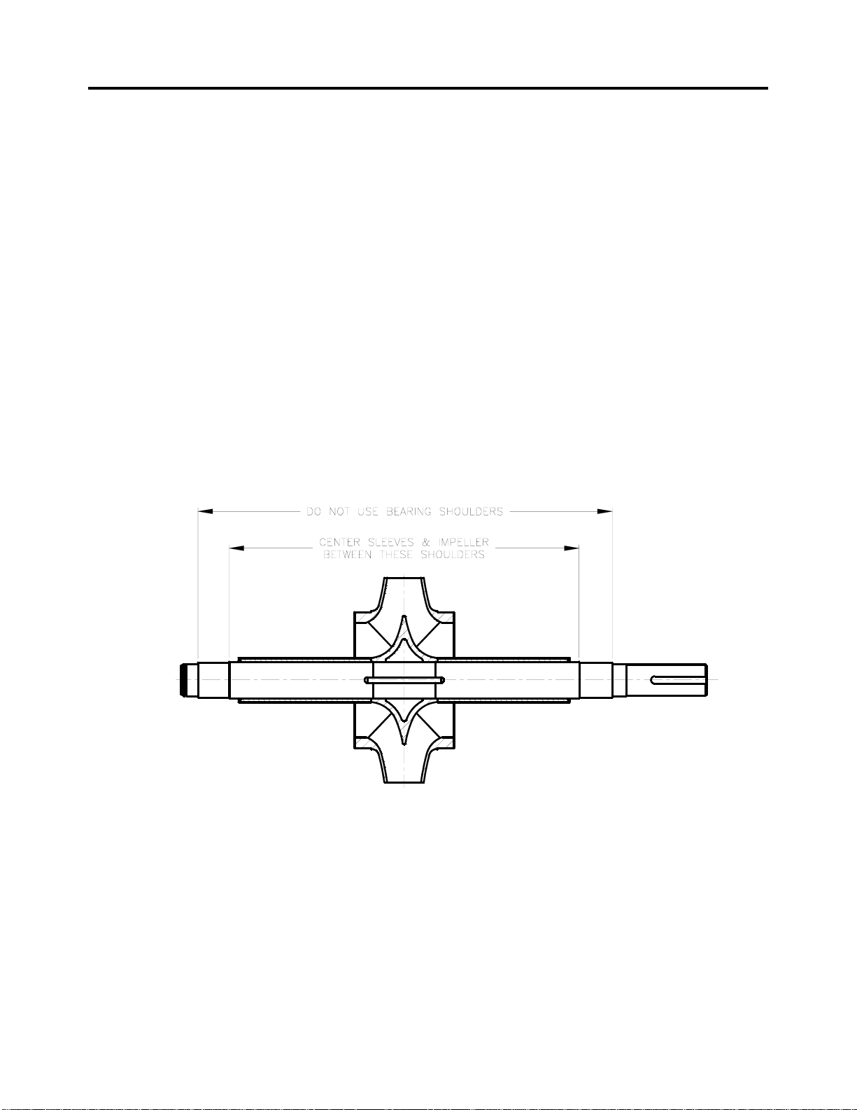
C. Install the impeller key (102) in the shaft (4) and slide the impeller (1) over the key, centering it between
the shaft shoulders as shown in Figure 5.
FIGURE 5
CAUTION: IF THE SHAFT SLEEVES ON YOUR PUMP ARE SECURED WITH LOCTITE ONLY,
REFER TO THE SHAFT SLEEVE INSTALLATION INSTRUCTIONS BEFORE
D. Install the shaft sleeves (A14 or B14), shaft sleeve nuts (213) and O-rings (452), if your pump uses
them, on the shaft. The shaft sleeves will be secured by one of three methods and you should proceed
as follows:
Sleeves Secured With Loctite And Sleeve Nuts: Apply two beads of Loctite No. 601 around the
shaft on the shaft/shaft sleeve fit, one approximately 2 inches from the impeller hub and the second at
the threaded end. Slide the shaft sleeves part way onto the shaft and rotate them at least one full
revolution to evenly spread the Loctite, then slide the sleeves over the shaft until they butt firmly against
the impeller hub. Install and tighten the shaft sleeve nuts (213) and the set screws (213A).
INSTALLING THE IMPELLER.
Page 20

MAINTENANCE (continued) PAGE 17
7. PUMP ASSEMBLY (continued)
Sleeves Secured With Loctite Only: Clean the shaft, the bore of the sleeves and the bore of the
impeller with Loctite “Safety Solvent #75559.
Install the impeller key in the shaft and coat the impeller area on the shaft with Loctite 601. Press the
impeller onto the shaft, centering it between the shoulders as shown in Figure 5.
Coat the shaft on the shaft/sleeve fit and the bore of the sleeves with Loctite 601. Slide the sleeves
part way onto the shaft and rotate them at least one full revolution to evenly spread the Loctite, then
slide the sleeves over the shaft until they butt firmly against the impeller hub. Check the sleeve location
again and let the Loctite cure for 8 hours before completing the pump assembly.
Sleeves Installed With O-rings: Slide the shaft sleeves over the shaft until they engage the key and
butt firmly against the impeller hub. Install the O-rings in the outboard shaft sleeve nut end of the
sleeve and tighten the shaft sleeve nuts and setscrews.
CAUTION: THE LINEAR POSITION OF THE IMPELLER MUST BE OBTAINED AND THE SHAFT
SLEEVES MUST BE PROPERLY LOCATED. REFER TO FIGURE 5 ON THE
PREVIOUS PAGE OF THIS MANUAL. IF PROVIDED, THE SHAFT SLEEVE NUST
MUST BE TIGHTENED WITHIN 10 MINUTES AFTER THE LOCTITE IS APPLIED. TO
ACCOMPLISH LINEAR POSITIONING OF THE IMPELLER, LEAVE AN EQUAL
AMOUNT OF SHAFT OR SHAFT THREADS EXPOSED ON EACH END OF THE SHAFT
AFTER ASSEMBLY IS COMPLETED. ALLOW 4 HOURS FOR THE LOCTITE TO CURE
BEFORE COMPLETING THE PUMP ASSEMBLY.
CAUTION: THIS PUMP MAY BE SUPPLIED IN SEVERAL DIFFERENT CONFIGURATIONS. EACH
USES DIFFERENT BEARING COVERS AND HOUSINGS WITH DIFFERENT DRAWING
REFERENCE NUMBERS. DESPITE THE FOLLOWING INSTRUCTIONS, ALWAYS
REFER TO THE SECTIONAL DRAWINGS CONTAINED IN THIS MANUAL BEFORE
PROCEEDING, TO INSURE THAT YOU HAVE INSTALLED ALL REQUIRED LIP
SEALS, O-RINGS, ETC.
E. If your pump is oil lubricated, install the lip seals (159C) in the outboard and inboard bearing covers
(B159) and the lip seal and the lip seal (158C) in the inboard bearing housing (C158). Assemble the
O-rings (159A) on the bearing housing covers prior to installing the bearings.
F. If your pump is equipped with mechanical seals or solid packing glands, install the seals (456) and
mechanical seal glands (B31) or solid packing glands before proceeding. Refer to the seal
manufacturer’s instructions for installation.
G. Install the water slingers (126) on each end of the shaft.
H. Install the outboard and inboard bearing covers (A159 or B159) on the shaft.
I. Install the outboard (168) and inboard bearings (163).
WARNING: TO PREVENT POSSIBLE SERIOUS PERSONAL INJURY AND DAMAGE TO THE
BEARINGS, PRESSURE SHOULD BE APPLIED TO THE INNER BEARING RACE
ONLY.
Note: The pump is designed to have a .000 to .001 interference fit between the bearings and
the shaft.
J. Install the snap ring (345) on the outboard end of the shaft. Pack both bearings approximately one-
half full of lithium base NGLI2 all-purpose bearing grease.
K. Install bearing housings (A158 and B158 if grease lubricated, or C158 and D158 or E158 and F158)
over the bearings and securely bolt the bearing covers to the bearing housings using the appropriate
capscrews (159D)
L. Using a double rope sling, carefully lower the rotor assembly into the lower casing (2).
WARNING: BE CAREFUL WHEN POSITIONING THE ROPES TO AVOID THE ROTOR SLIPPING
AND CAUSING POSSIBLE SERIOUS PERSONAL INJURY.
CAUTION: WHEN LOWERING THE ROTOR, BE CAREFUL T O PROPERLY POSITION THE
WEARING RINGS. FAILURE TO DO SO COULD SERIOUSLY DAMAGE THE RINGS.
Page 21

PAGE 18 MAINTENANCE (continued)
7. PUMP ASSEMBLY (continued)
M. Attach the bearing housings to the lower casing using the appropriate dowel pins (158A) and
CAUTION: BE SURE BEARING HOUSING/CASING MATING SURFACES ARE CLEAN AND FREE FROM
The pump assembly is now complete except for packing adjustment, which should be accomplished after the
pump is installed, primed and started up. Refer to the maintenance section of this manual for specific packing
adjustment instructions.
capscrews (158B).
BURRS, AS THIS WILL AFFECT THE ALIGNMENT OF THE ROTOR/CASING.
N. Inspect the upper casing (3) to assure that the water passage is clean and free from foreign material.
Apply a light coat of grease to the upper and lower casing mating surfaces and install a new casing
gasket (157) on the lower casing, making sure the holes are aligned. Position the pins in the casing
wearing rings to align with the slots in the lower casing. Lower the upper casing into position. Install
the casing alignment pins (2B) and securely bolt the upper and lower casing together using th e
capscrews (2A).
O. Install the packing (212), lantern rings (10), split glands (19) and gl and nuts (31B).
Page 22
REPAIR PARTS PAGE 19
y
Y
ORDERING PARTS
There are a variety of options available for this pump. When ordering parts, give the pump serial number, size
and figure number and a complete description and item number of each part. Refer to the drawings and parts
list in the back of this manual. You should order parts from your local Aurora Pump distributor. Consult your
local telephone yellow pages for the office nearest you.
RETURNING PARTS
Unnecessary delays and wasted effort will be avoided if you use the proper procedure to return parts or
equipment. All materials or parts returned to the factory must have prior approval and a “Returned Goods Tag.”
Contact your nearest Aurora Pump distributor, listing the material to be returned and the reason for the return.
He will contact the factory to obtain the required approval and “Returned Goods Tag.” All materials to be
returned should be carefully packaged to avoid damage in route from rough handling or exposure to weather.
The “Returned Goods Tag” will give shipping instructions. All material is to be returned freight prepaid.
Aurora Pump makes improvements on its products from time to time and reserves the right to furnish improved
parts for repairs. A part that is received and is not identical in appearance, or has a different symbol from the
original part, may still be interchangeable. Examine the part carefully before contacting your Aurora Pump
distributor. The parts should never be returned to the factory without first obtaining proper authori zation fro m
your Aurora Pump distributor.
RECOMMENDED SPARE PARTS
For Normal Dut
:
REF. NO. DESCRIPTION
A14 SLEEVE, SHAFT
B14 SLEEVE, SHAFT
16 WEARING RING, CASING
17 WEARING RING, IMPELLER (IF ON ORIGINAL CONSTRUCTION)
163 BEARING, INBOARD
168 BEARING, OUTBOARD
212 PACKING (OR MECHANICAL SEAL - 456)
GASKETS, COMPLETE SET
For Severe Duty, Add The Following:
REF. NO. DESCRIPTION
COMPLETE ROTATING ASSEMBL
Page 23

PAGE 20 NOTES
Page 24

NOTES PAGE 21
Page 25

PAGE 22 NOTES
Page 26
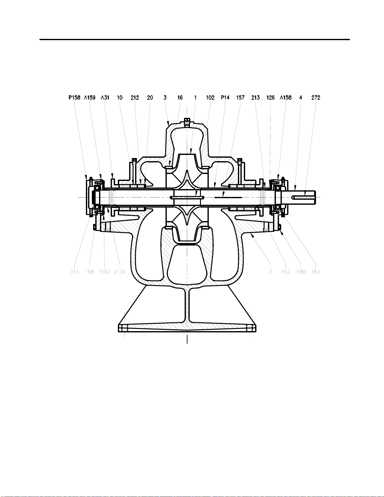
SECTIONAL DRAWING PAGE 23
Figure 6
STANDARD CONSTRUCTION
Page 27
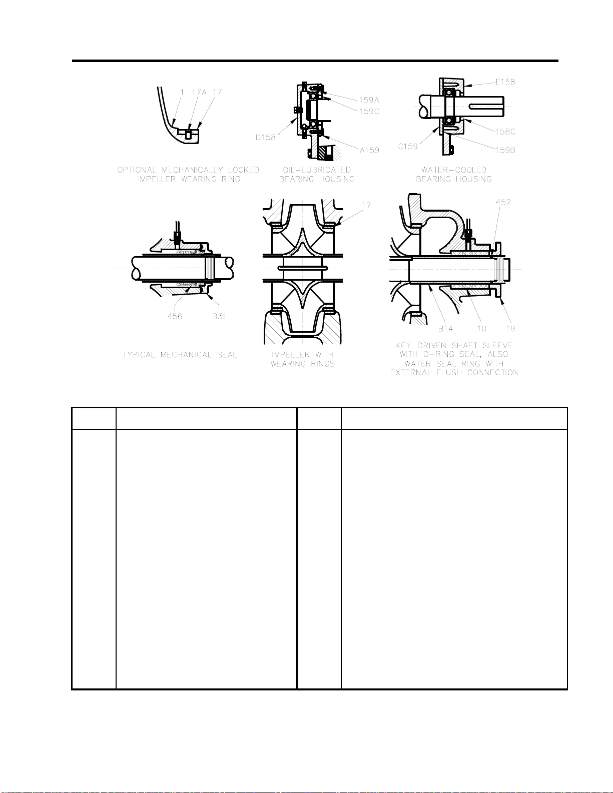
PAGE 24 SECTIONAL DRAWINGS
REF.
NO.
1
2
2A *
2B *
2C *
3
4
10
A14
B14
16
17
17A
19
20
A31
B31
31A *
31B *
102
126
157
A158
B158
* Not Shown
DESCRIPTION
IMPELLER
CASING, LOWER HALF
CAPSCREWS, CASING
PIN, CASING ALIGNMENT
PIPE PLUG, CASING
CASING, UPPER HALF
SHAFT
LANTERN RING
SHAFT SLEEVE
SHAFT SLEEVE, KEYED
WEARING RING, CASING
WEARING RING, IMPELLER
SETSCREW
PACKING GLAND, SPLIT
WASHER, PACKING BOX
PACKING GLAND, SOLID
GLAND, MECHANICAL SEAL
GLAND STUD
GLAND NUT
KEY, IMPELLER
WATER SLINGER
GASKET, CASING
BEARING HOUSING, INBOARD, GREASE LUBE
BEARING HOUSING, OUTBOARD, GREASE LUBE
Figure 7
REF.
NO.
C158 *
D158
E158 *
F158
158A *
158B *
158C
158D *
A159
B159
C159
159A
159B
159C
159D *
163
168
212
213
213A
272
345
452
456
DESCRIPTION
BEARING HOUSING, INBOARD, OIL LUBE
BEARING HOUSING, OUTBOARD, OIL LUBE
BEARING HOUSING, INBOARD, WATER-COOLED BEARING
BEARING HOUSING, OUTBOARD, WATER-COOLED BEARING
PIN, BEARING HOUSING ALIGNMENT
CAPSCREW, HOUSING
LIPSEAL
PIPE PLUG, HOUSING
BEARING HOUSING COVER, GREASE LUBE
BEARING HOUSING COVER, OIL LUBE
BEARING HOUSING COVER, WATER-COOLED BEARING
O-RING, OIL LUBE COVER
O-RING, WATER-COOLED COVER
LIPSEAL
CAPSCREW, HOUSING COVER
BEARING, INBOARD
BEARING, OUTBOARD
PACKING
NUT, SHAFT SLEEVE
SETSCREW
KEY, COUPLING
SNAP RING
O-RING, SHAFT SLEEVE
SEAL, MECHANICAL
 Loading...